EP4170821B1 - Rfic assembled antenna - Google Patents
Rfic assembled antenna Download PDFInfo
- Publication number
- EP4170821B1 EP4170821B1 EP22201951.5A EP22201951A EP4170821B1 EP 4170821 B1 EP4170821 B1 EP 4170821B1 EP 22201951 A EP22201951 A EP 22201951A EP 4170821 B1 EP4170821 B1 EP 4170821B1
- Authority
- EP
- European Patent Office
- Prior art keywords
- slot
- rfic
- pattern
- layer substrate
- present disclosure
- Prior art date
- Legal status (The legal status is an assumption and is not a legal conclusion. Google has not performed a legal analysis and makes no representation as to the accuracy of the status listed.)
- Active
Links
Images





Classifications
-
- H—ELECTRICITY
- H01—ELECTRIC ELEMENTS
- H01Q—ANTENNAS, i.e. RADIO AERIALS
- H01Q19/00—Combinations of primary active antenna elements and units with secondary devices, e.g. with quasi-optical devices, for giving the antenna a desired directional characteristic
- H01Q19/28—Combinations of primary active antenna elements and units with secondary devices, e.g. with quasi-optical devices, for giving the antenna a desired directional characteristic using a secondary device in the form of two or more substantially straight conductive elements
- H01Q19/30—Combinations of primary active antenna elements and units with secondary devices, e.g. with quasi-optical devices, for giving the antenna a desired directional characteristic using a secondary device in the form of two or more substantially straight conductive elements the primary active element being centre-fed and substantially straight, e.g. Yagi antenna
-
- G—PHYSICS
- G06—COMPUTING OR CALCULATING; COUNTING
- G06K—GRAPHICAL DATA READING; PRESENTATION OF DATA; RECORD CARRIERS; HANDLING RECORD CARRIERS
- G06K19/00—Record carriers for use with machines and with at least a part designed to carry digital markings
- G06K19/06—Record carriers for use with machines and with at least a part designed to carry digital markings characterised by the kind of the digital marking, e.g. shape, nature, code
- G06K19/067—Record carriers with conductive marks, printed circuits or semiconductor circuit elements, e.g. credit or identity cards also with resonating or responding marks without active components
- G06K19/07—Record carriers with conductive marks, printed circuits or semiconductor circuit elements, e.g. credit or identity cards also with resonating or responding marks without active components with integrated circuit chips
- G06K19/077—Constructional details, e.g. mounting of circuits in the carrier
- G06K19/07749—Constructional details, e.g. mounting of circuits in the carrier the record carrier being capable of non-contact communication, e.g. constructional details of the antenna of a non-contact smart card
- G06K19/0775—Constructional details, e.g. mounting of circuits in the carrier the record carrier being capable of non-contact communication, e.g. constructional details of the antenna of a non-contact smart card arrangements for connecting the integrated circuit to the antenna
-
- H—ELECTRICITY
- H01—ELECTRIC ELEMENTS
- H01Q—ANTENNAS, i.e. RADIO AERIALS
- H01Q1/00—Details of, or arrangements associated with, antennas
- H01Q1/12—Supports; Mounting means
- H01Q1/22—Supports; Mounting means by structural association with other equipment or articles
- H01Q1/2283—Supports; Mounting means by structural association with other equipment or articles mounted in or on the surface of a semiconductor substrate as a chip-type antenna or integrated with other components into an IC package
-
- H—ELECTRICITY
- H01—ELECTRIC ELEMENTS
- H01Q—ANTENNAS, i.e. RADIO AERIALS
- H01Q1/00—Details of, or arrangements associated with, antennas
- H01Q1/36—Structural form of radiating elements, e.g. cone, spiral, umbrella; Particular materials used therewith
- H01Q1/38—Structural form of radiating elements, e.g. cone, spiral, umbrella; Particular materials used therewith formed by a conductive layer on an insulating support
-
- H—ELECTRICITY
- H01—ELECTRIC ELEMENTS
- H01Q—ANTENNAS, i.e. RADIO AERIALS
- H01Q1/00—Details of, or arrangements associated with, antennas
- H01Q1/52—Means for reducing coupling between antennas; Means for reducing coupling between an antenna and another structure
- H01Q1/526—Electromagnetic shields
-
- H—ELECTRICITY
- H01—ELECTRIC ELEMENTS
- H01Q—ANTENNAS, i.e. RADIO AERIALS
- H01Q23/00—Antennas with active circuits or circuit elements integrated within them or attached to them
-
- H—ELECTRICITY
- H01—ELECTRIC ELEMENTS
- H01Q—ANTENNAS, i.e. RADIO AERIALS
- H01Q3/00—Arrangements for changing or varying the orientation or the shape of the directional pattern of the waves radiated from an antenna or antenna system
- H01Q3/26—Arrangements for changing or varying the orientation or the shape of the directional pattern of the waves radiated from an antenna or antenna system varying the relative phase or relative amplitude of energisation between two or more active radiating elements; varying the distribution of energy across a radiating aperture
- H01Q3/267—Phased-array testing or checking devices
-
- H—ELECTRICITY
- H01—ELECTRIC ELEMENTS
- H01Q—ANTENNAS, i.e. RADIO AERIALS
- H01Q9/00—Electrically-short antennas having dimensions not more than twice the operating wavelength and consisting of conductive active radiating elements
- H01Q9/04—Resonant antennas
- H01Q9/16—Resonant antennas with feed intermediate between the extremities of the antenna, e.g. centre-fed dipole
- H01Q9/28—Conical, cylindrical, cage, strip, gauze, or like elements having an extended radiating surface; Elements comprising two conical surfaces having collinear axes and adjacent apices and fed by two-conductor transmission lines
- H01Q9/285—Planar dipole
Definitions
- the present disclosure relates to an antenna, and more particularly to an RFICz assembled antenna.
- 5G communication has been started, in which 5G performs communication using a millimeter wave band of 20 GHz or more compared to the existing 4G communication.
- the millimeter wave band has a very large attenuation characteristic compared to the low frequency band, and the signal loss due to an obstacle is very large.
- a conventional millimeter wave band antenna for a terminal was connected to a board of the terminal through a connector, and received a feed signal from an RFIC chip mounted on the board of the terminal.
- the millimeter wave band antenna has a small size
- a connector with fine precision was also required for the connector, and sophisticated work was also required to combine the millimeter wave band antenna with the connector.
- the connector due to the use of the connector, there was a problem that not only the size of the entire terminal increases, but also the manufacturing cost increases.
- US 9 806 422 B2 package structures are provided having antenna-in-packages that are integrated with semiconductor RFIC (radio frequency integrated circuit) chips to form compact integrated radio/wireless communications systems that operate in the millimeter wave (mmWave) frequency range with radiation in broadside and end-fire directions.
- RFIC radio frequency integrated circuit
- a dipole antenna element is provided at the back of a dielectric substrate set to the reflector surface.
- a parasitic element is provided on the front of the dielectric substrate, which is constituted by forming and protruding the central portion of a linear conductor forward in an almost trapezoidal shape, for example.
- An object of the present disclosure is to propose a millimeter wave band antenna having a structure in which an RFIC chip is assembled without being connected to an RFIC chip through a connector.
- Another object of the present disclosure is to propose a millimeter wave band antenna capable of reducing the size of a terminal and reducing manufacturing cost.
- Yet another object of the present disclosure is to propose a millimeter wave band antenna capable of forming a required radiation pattern while effectively blocking harmful electromagnetic waves.
- an RFIC assembled antenna comprising: a first layer substrate including a first metal pattern, a first slot formed in the first metal pattern, and a second slot formed in the first metal an RFIC chip which is coupled to a region of the second slot for assembling the RFIC chip with the first layer substrate; and a second layer substrate coupled to a lower portion of the first layer substrate and including a second metal pattern, a third slot formed in the second metal pattern, and a dipole radiator formed inside the third slot, wherein a feeding pattern connected to the RFIC chip to provide a feed signal to the dipole radiator is formed inside the first slot wherein the second slot is connected to the first slot.
- At least one parasitic pattern spaced apart from the feeding pattern by a predetermined distance and extending in a direction perpendicular to the longitudinal direction of the feeding pattern is formed inside the first slot.
- An auxiliary radiator spaced apart from the feeding pattern by a predetermined distance and extending in a direction parallel to the longitudinal direction of the feeding pattern is further formed inside the first slot, and the auxiliary radiator is connected to the RFIC chip.
- the auxiliary radiator receives a portion of the signal radiated from the dipole radiator and provides it to the RFIC chip.
- the antenna further includes a third layer substrate positioned below the second layer substrate, and at least one reflector is formed on the third layer substrate in a region that vertically overlaps with the first slot and the second slot.
- the antenna is coupled to an SMT region of a terminal board, and at least one via hole for providing a feed signal from the terminal board to the RFIC chip is formed in the first to third layer substrates.
- an RFIC assembled antenna comprising: a first layer substrate including a first metal pattern, a first slot formed in the first metal pattern, and a second slot formed to be connected to the first slot, and in which an RFIC chip is coupled to a region of the second slot; and a second layer substrate coupled to a lower portion of the first layer substrate and including a second metal pattern and a dipole radiator coupled to the second metal pattern, wherein a feeding pattern connected to the RFIC chip to provide a feed signal to the dipole radiator is formed inside the first slot or the second slot, and wherein a shield can for shielding the RFIC chip is coupled to a region of the second slot of the first layer substrate.
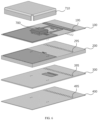
- FIG. 1 is an exploded perspective view showing a structure of an RFIC assembled antenna according to an embodiment of the present disclosure
- FIG. 2 is a plan view of a first layer substrate in an RFIC assembled antenna according to an embodiment of the present disclosure
- FIG. 3 is a plan view of a second layer substrate in an RFIC assembled antenna according to an embodiment of the present disclosure
- FIG. 4 is a plan view of a third layer substrate
- FIG. 5 is a plan view of a fourth layer substrate according to an embodiment of the present disclosure.
- the RFIC assembled antenna may include first to fourth layer substrates 100, 200, 300 and 400.
- the multi-layer structure for the RFIC assembled antenna of the present disclosure may be implemented using a multi-layer PCB.
- FIG. 1 illustrates a case composed of four layer substrates, it will be apparent to those skilled in the art that additional substrates may be provided to control the separation distance between respective substrates and to control the characteristics. In addition, it will also be apparent to those skilled in the art that certain layer substrates may be omitted.
- a first metal pattern 110 is formed on the first layer substrate 100.
- the first metal pattern 110 may have a ground potential.
- a first slot 120 and a second slot 130 are formed in the first metal pattern 110.
- the first slot 120 and the second slot 130 are formed by removing a portion of the metal region of the first metal pattern 110.
- the feeding pattern 140 is connected to the RFIC chip in the region of the second slot 130, and receives a feed signal from the RFIC chip.
- the feeding pattern 140 functions to provide a feed signal to the dipole radiator 230 formed on the second layer substrate 200 in a coupling manner.
- a ' '-shaped feeding pattern 140 is shown, but the shape of the feeding pattern 140 may be changed as needed.
- the first parasitic pattern 160 formed in the first slot 120 or the second slot 130 may be formed in a direction perpendicular to the longitudinal direction of the feeding pattern 140.
- the first parasitic pattern 160 is not electrically connected to the ground or signal line, and the first parasitic pattern 160 is formed to improve the gain of the radiation pattern of the dipole radiator 230 formed on the second layer substrate 200.
- the length of the first parasitic pattern 160 may be determined based on a used frequency and a required radiation pattern.
- a second parasitic pattern 170 and a third parasitic pattern 180 may be additionally formed in the first slot 120.
- the second parasitic pattern 170 and the third parasitic pattern 180 may be spaced apart from the first parasitic pattern 160, and formed in a direction parallel to the first parasitic pattern 160.
- the second parasitic pattern 170 and the third parasitic pattern 180 are also not electrically connected to the ground or the signal line.
- the second parasitic pattern 170 is spaced apart from the first parasitic pattern 160
- the third parasitic pattern 180 is spaced apart from the second parasitic pattern 170
- the third parasitic pattern 180 is disposed to be spaced apart from the first parasitic pattern by a greater distance compared to the second parasitic pattern 170.
- the third parasitic pattern 180 may be disposed adjacent to the edge region of the first slot.
- the second parasitic pattern 170 and the third parasitic pattern 180 also function to improve the gain of the radiation pattern.
- the auxiliary radiator 150 is electrically connected to the RFIC chip, and receives a portion of a signal radiated from the dipole radiator 230.
- the auxiliary radiator 150 receives a portion of a signal radiated from the dipole radiator 230.
- the auxiliary radiator 150 is used for determining whether a signal radiated from the dipole radiator 230 is appropriate, and receives a portion of the radiation signal.
- the signal received from the auxiliary radiator 150 is provided to the RFIC chip, and it is possible to determine whether the antenna malfunctions by analyzing the signal provided to the RFIC chip through the auxiliary radiator 150.
- a second slot 130 connected to the first slot 120 is formed in the first metal pattern 110 of the first layer substrate 100.
- the second slot 130 is a slot for placing an RFIC chip.
- a shield can may be disposed to shield the RFIC chip, and the shield can is also disposed in the region of the second slot 130.
- the second slot 130 is connected to the first slot 120, the width and shape are different from those of the first slot 120.
- a third metal pattern 190 is formed spaced apart from the first metal pattern 110, and a plurality of first via holes 195 are formed in the third metal pattern 190.
- the plurality of first via holes 195 may be formed in the longitudinal direction of the third metal pattern 190, and the plurality of first via holes 195 may be arranged to form two rows.
- the arrangement of the plurality of first via holes 195 illustrated in FIG. 1 is exemplary, and the plurality of first via holes 195 may be arranged in various ways.
- the radiation pattern of the antenna may be affected. Although the radiation pattern should be formed in a direction passing through the first slot and the second slot, the radiation pattern may be tilted due to the influence of the RFIC chip and the shield can.
- a third metal pattern 190 spaced apart from the first metal pattern is formed, and a plurality of first via holes 195 are formed in the third metal pattern 190.
- Via holes connected to the third metal pattern 190 are also formed in the second layer substrate 200, the third layer substrate 300 and the fourth layer substrate 400.
- a plurality of second via holes 295 connected to the first via holes 195 are formed in the second layer substrate 200
- a plurality of third via holes 395 connected to the plurality of second via holes 295 are formed in the third layer substrate 300
- a plurality of fourth via holes 495 connected to the plurality of third via holes 395 are formed in the fourth layer substrate 400.
- a conductive wall may be formed by forming via holes connected to each other in the first layer substrate 100 to the fourth layer substrate 400, and distortion of the radiation pattern can be prevented through the conductive wall.
- a second metal pattern 210 is formed on the second layer substrate 200.
- the second metal pattern 210 may have a ground potential.
- a dipole radiator 230 coupled to the second metal pattern 210 is formed on the second layer substrate 200.
- the dipole radiator 230 receives a feed signal from the feeding pattern 140 in a coupling manner.
- the dipole radiator 230 radiates the feed signal provided from the feeding pattern 140 to the outside.
- the dipole radiator 230 includes a first dipole arm 230-1 and a second dipole arm 230-2.
- the first dipole arm 230-1 and the second dipole arm 230-2 are spaced apart from each other.
- FIG. 3 a case is shown in which a dipole radiator 230 is used as the antenna radiator of the present disclosure, but it will be apparent to those skilled in the art that other types of radiator may be formed.
- reflectors 410 and 412 are formed on the third layer substrate 300.
- the reflectors 410 and 412 are preferably formed in a region overlapping the first slot 120 and the second slot 130 vertically. In FIG. 4 , a case is shown in which the two reflectors 410 and 412 are spaced apart from each other, but it will be apparent to those skilled in the art that a single reflector may be substituted.
- the reflectors 410 and 412 reflect the signals radiated in the downward direction among the radiation signals of the dipole radiator 230 to increase the gain in the upward direction of the radiation signals of the dipole radiator 230.
- the fourth layer substrate 400 is coupled to the lower portion of the third layer substrate 300.
- a ground plane (not shown) may be formed on a lower surface of the fourth layer substrate 400.
- FIG. 6 is an exploded perspective view of a state in which an RFIC is coupled in an antenna according to an embodiment of the present disclosure
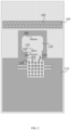
- FIG. 7 is a plan view of a first layer substrate to which an RFIC is coupled.
- an RFIC chip 700 is coupled to the region of the second slot 130 of the antenna according to an embodiment of the present disclosure, and a shield can 710 for shielding the RFIC chip is coupled.
- the shield can 710 may not be coupled as needed.
- the RFIC chip 700 provides a feed signal to the feeding pattern 140, and the feeding pattern 140 is electrically connected to the RFIC chip 700.
- the RFIC chip 700 is electrically connected to the auxiliary radiator 150 to receive a signal received from the auxiliary radiator 150.
- the present disclosure proposes an antenna structure in which an RFIC chip is assembled without using a separate connector, by laminating the first layer substrate 100 on the second layer substrate 200 on which the dipole radiator 230 is formed, forming the first metal pattern 110 in which the first slot 120 and the second slot 130 are formed, and then coupling the RFIC chip on the first metal pattern 110.
- the RFIC chip 700 receives a feed signal from the PCB of the terminal, and via holes are formed in each layer substrate of the present disclosure to receive the feed signal from the PCB.
- FIGS. 6 and 7 an example is shown in which two via holes are formed on the left side and two via holes on the right side with respect to the RFIC chip.
- a shield can 710 for shielding the RFIC chip 700 may be additionally coupled.
- the shield can 710 is made of a conductive material, it may block unnecessary electromagnetic waves generated from the RFIC chip 700, but may distort the radiation pattern of the dipole radiator 230.
- a conductive wall is formed through the via holes 195, 295, 395 and 495 of each layer substrate.
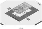
- FIG. 8 shows an example in which an RFIC assembled antenna according to an embodiment of the present disclosure is coupled on a substrate.
- an SMT region is set on the substrate, and the antenna made of the multi-layer substrate of the present disclosure is coupled to the SMT region. Since the antenna of the present disclosure has a structure in which the RFIC chip is assembled, it can be directly coupled to the substrate without being coupled to the substrate through a separate connector.
- via holes are formed in the antenna of the present disclosure so that a feed signal from the substrate is provided to the RFIC chip.
- FIG. 9 shows an example of a radiation pattern of an RFIC assembled antenna according to an embodiment of the present disclosure.
- a radiation pattern is formed in an upward direction of the antenna.
- the gain of the beam in the upward direction can be improved due to the first slot 120, the second slot 130 and the plurality of via holes.
- the reflectors 410 and 412 formed on the third layer substrate 300 may also contribute to the improvement of the gain of the beam, and the conductive wall formed through the plurality of via holes 195, 295, 395 and 495 may prevent the radiation pattern from being tilted.
- the auxiliary radiator 150 is located on the first layer substrate 100 that is an upper portion of the dipole radiator 230, it is possible to receive a portion of the signal radiated from the dipole radiator 230 to confirm whether an appropriate signal is radiated in an appropriate direction.
Landscapes
- Engineering & Computer Science (AREA)
- Microelectronics & Electronic Packaging (AREA)
- Physics & Mathematics (AREA)
- Computer Hardware Design (AREA)
- General Physics & Mathematics (AREA)
- Theoretical Computer Science (AREA)
- Electromagnetism (AREA)
- Aerials With Secondary Devices (AREA)
- Variable-Direction Aerials And Aerial Arrays (AREA)
Description
- This application claims priority from
Korean Patent Application No. 10-2021-0141695, filed on October 22, 2021 Korean Patent Application No. 10-2022-0012395, filed on January 27, 2022 - The present disclosure relates to an antenna, and more particularly to an RFICz assembled antenna.
- In recent years, 5G communication has been started, in which 5G performs communication using a millimeter wave band of 20 GHz or more compared to the existing 4G communication. The millimeter wave band has a very large attenuation characteristic compared to the low frequency band, and the signal loss due to an obstacle is very large.
- In the 5G band, very large-capacity IoT data, 360-degree video data, VR data, and various types of big data are supported through mobile communication networks, and for this reason, communication using the millimeter wave band is essential.
- In the millimeter wave band, it has a very large attenuation characteristic, and for this reason, an antenna for millimeter wave requires high directivity.
- Meanwhile, since the millimeter wave band is a very high frequency band, the size of the antenna is also reduced. A conventional millimeter wave band antenna for a terminal was connected to a board of the terminal through a connector, and received a feed signal from an RFIC chip mounted on the board of the terminal.
- Since the millimeter wave band antenna has a small size, a connector with fine precision was also required for the connector, and sophisticated work was also required to combine the millimeter wave band antenna with the connector. Furthermore, due to the use of the connector, there was a problem that not only the size of the entire terminal increases, but also the manufacturing cost increases.
- In the
US 9 806 422 B2 - In the
US 6 008 773 A a dipole antenna element is provided at the back of a dielectric substrate set to the reflector surface. A parasitic element is provided on the front of the dielectric substrate, which is constituted by forming and protruding the central portion of a linear conductor forward in an almost trapezoidal shape, for example. - An object of the present disclosure is to propose a millimeter wave band antenna having a structure in which an RFIC chip is assembled without being connected to an RFIC chip through a connector.
- Another object of the present disclosure is to propose a millimeter wave band antenna capable of reducing the size of a terminal and reducing manufacturing cost.
- Yet another object of the present disclosure is to propose a millimeter wave band antenna capable of forming a required radiation pattern while effectively blocking harmful electromagnetic waves.
- According to one aspect of the present disclosure, conceived to achieve the objectives above, an RFIC assembled antenna is provided, the antenna comprising: a first layer substrate including a first metal pattern, a first slot formed in the first metal pattern, and a second slot formed in the first metal an RFIC chip which is coupled to a region of the second slot for assembling the RFIC chip with the first layer substrate; and a second layer substrate coupled to a lower portion of the first layer substrate and including a second metal pattern, a third slot formed in the second metal pattern, and a dipole radiator formed inside the third slot, wherein a feeding pattern connected to the RFIC chip to provide a feed signal to the dipole radiator is formed inside the first slot wherein the second slot is connected to the first slot.
- At least one parasitic pattern spaced apart from the feeding pattern by a predetermined distance and extending in a direction perpendicular to the longitudinal direction of the feeding pattern is formed inside the first slot.
- An auxiliary radiator spaced apart from the feeding pattern by a predetermined distance and extending in a direction parallel to the longitudinal direction of the feeding pattern is further formed inside the first slot, and the auxiliary radiator is connected to the RFIC chip.
- The auxiliary radiator receives a portion of the signal radiated from the dipole radiator and provides it to the RFIC chip.
- The antenna further includes a third layer substrate positioned below the second layer substrate, and at least one reflector is formed on the third layer substrate in a region that vertically overlaps with the first slot and the second slot.
- The antenna is coupled to an SMT region of a terminal board, and at least one via hole for providing a feed signal from the terminal board to the RFIC chip is formed in the first to third layer substrates.
- According to a comparative aspect of the present disclosure, an RFIC assembled antenna is provided, the antenna comprising: a first layer substrate including a first metal pattern, a first slot formed in the first metal pattern, and a second slot formed to be connected to the first slot, and in which an RFIC chip is coupled to a region of the second slot; and a second layer substrate coupled to a lower portion of the first layer substrate and including a second metal pattern and a dipole radiator coupled to the second metal pattern, wherein a feeding pattern connected to the RFIC chip to provide a feed signal to the dipole radiator is formed inside the first slot or the second slot, and wherein a shield can for shielding the RFIC chip is coupled to a region of the second slot of the first layer substrate.
- According to the present disclosure, since it has a structure in which an RFIC chip is assembled with an antenna, the size of the terminal can be reduced, the manufacturing cost can be reduced, and it can effectively block electromagnetic interference caused by the integration of the RFIC chip.
-
-
FIG. 1 is an exploded perspective view showing a structure of an RFIC assembled antenna according to an embodiment of the present disclosure. -
FIG. 2 is a plan view of a first layer substrate in an RFIC assembled antenna according to an embodiment of the present disclosure. -
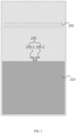
FIG. 3 is a plan view of a second layer substrate in an RFIC assembled antenna according to an embodiment of the present disclosure. -
FIG. 4 is a plan view of a third layer substrate in an RFIC assembled antenna according to an embodiment of the present disclosure. -
FIG. 5 is a plan view of a fourth layer substrate in an RFIC assembled antenna according to an embodiment of the present disclosure. -
FIG. 6 is an exploded perspective view of a state in which an RFIC is coupled in an antenna according to an embodiment of the present disclosure. -
FIG. 7 is a plan view of a first layer substrate to which an RFIC is coupled. -
FIG. 8 shows an example in which an RFIC assembled antenna according to an embodiment of the present disclosure is coupled on a substrate. -
FIG. 9 shows an example of a radiation pattern of an RFIC assembled antenna according to an embodiment of the present disclosure. - In order to fully understand the present disclosure, operational advantages of the present disclosure, and objects achieved by implementing the present disclosure, reference should be made to the accompanying drawings illustrating preferred embodiments of the present disclosure and to the contents described in the accompanying drawings.
- Hereinafter, the present disclosure will be described in detail by describing preferred embodiments of the present disclosure with reference to accompanying drawings. However, the present disclosure can be implemented in various different forms and is not limited to the embodiments described herein. For a clearer understanding of the present disclosure, parts that are not of great relevance to the present disclosure have been omitted from the drawings, and like reference numerals in the drawings are used to represent like elements throughout the specification.
- Throughout the specification, reference to a part "including" or "comprising" an element does not preclude the existence of one or more other elements and can mean other elements are further included, unless there is specific mention to the contrary. Also, terms such as "unit", "device", "module", "block", and the like described in the specification refer to units for processing at least one function or operation, which may be implemented by hardware, software, or a combination of hardware and software.
-
FIG. 1 is an exploded perspective view showing a structure of an RFIC assembled antenna according to an embodiment of the present disclosure,FIG. 2 is a plan view of a first layer substrate in an RFIC assembled antenna according to an embodiment of the present disclosure, andFIG. 3 is a plan view of a second layer substrate in an RFIC assembled antenna according to an embodiment of the present disclosure.FIG. 4 is a plan view of a third layer substrate, andFIG. 5 is a plan view of a fourth layer substrate according to an embodiment of the present disclosure. - Referring to
FIG. 1 , the RFIC assembled antenna according to an embodiment of the present disclosure may include first tofourth layer substrates FIG. 1 illustrates a case composed of four layer substrates, it will be apparent to those skilled in the art that additional substrates may be provided to control the separation distance between respective substrates and to control the characteristics. In addition, it will also be apparent to those skilled in the art that certain layer substrates may be omitted. - Referring to
FIGS. 1 and2 , afirst metal pattern 110 is formed on thefirst layer substrate 100. Thefirst metal pattern 110 may have a ground potential. - A
first slot 120 and asecond slot 130 are formed in thefirst metal pattern 110. Thefirst slot 120 and thesecond slot 130 are formed by removing a portion of the metal region of thefirst metal pattern 110. - Inside the
first slot 120 and thesecond slot 130, afeeding pattern 140, anauxiliary radiator 150, a firstparasitic pattern 160, a secondparasitic pattern 170 and a thirdparasitic pattern 180 are formed. Thefirst slot 120 is formed so that thedipole radiator 230 formed in thesecond layer substrate 200 can radiate an RF signal with high gain through a narrower beamwidth. - The
feeding pattern 140 is connected to the RFIC chip in the region of thesecond slot 130, and receives a feed signal from the RFIC chip. Thefeeding pattern 140 functions to provide a feed signal to thedipole radiator 230 formed on thesecond layer substrate 200 in a coupling manner. InFIGS. 1 and2 , a ''-
shaped feeding pattern 140 is shown, but the shape of thefeeding pattern 140 may be changed as needed. - The first
parasitic pattern 160 formed in thefirst slot 120 or thesecond slot 130 may be formed in a direction perpendicular to the longitudinal direction of thefeeding pattern 140. The firstparasitic pattern 160 is not electrically connected to the ground or signal line, and the firstparasitic pattern 160 is formed to improve the gain of the radiation pattern of thedipole radiator 230 formed on thesecond layer substrate 200. The length of the firstparasitic pattern 160 may be determined based on a used frequency and a required radiation pattern. - Meanwhile, a second
parasitic pattern 170 and a thirdparasitic pattern 180 may be additionally formed in thefirst slot 120. The secondparasitic pattern 170 and the thirdparasitic pattern 180 may be spaced apart from the firstparasitic pattern 160, and formed in a direction parallel to the firstparasitic pattern 160. The secondparasitic pattern 170 and the thirdparasitic pattern 180 are also not electrically connected to the ground or the signal line. - The second
parasitic pattern 170 is spaced apart from the firstparasitic pattern 160, the thirdparasitic pattern 180 is spaced apart from the secondparasitic pattern 170, and the thirdparasitic pattern 180 is disposed to be spaced apart from the first parasitic pattern by a greater distance compared to the secondparasitic pattern 170. According to an embodiment of the present disclosure, the thirdparasitic pattern 180 may be disposed adjacent to the edge region of the first slot. The secondparasitic pattern 170 and the thirdparasitic pattern 180 also function to improve the gain of the radiation pattern. - The
auxiliary radiator 150 is electrically connected to the RFIC chip, and receives a portion of a signal radiated from thedipole radiator 230. Theauxiliary radiator 150 receives a portion of a signal radiated from thedipole radiator 230. Theauxiliary radiator 150 is used for determining whether a signal radiated from thedipole radiator 230 is appropriate, and receives a portion of the radiation signal. The signal received from theauxiliary radiator 150 is provided to the RFIC chip, and it is possible to determine whether the antenna malfunctions by analyzing the signal provided to the RFIC chip through theauxiliary radiator 150. - The present disclosure makes it possible to easily detect an antenna malfunction without using a separate diagnostic structure, by forming the
auxiliary radiator 150 in theslots first layer substrate 100 that is the upper layer of thesecond layer substrate 200 on which thedipole radiator 230 is formed. - A
second slot 130 connected to thefirst slot 120 is formed in thefirst metal pattern 110 of thefirst layer substrate 100. Although not shown inFIGS. 1 and2 , thesecond slot 130 is a slot for placing an RFIC chip. In addition, in an embodiment to be described later, a shield can may be disposed to shield the RFIC chip, and the shield can is also disposed in the region of thesecond slot 130. Although thesecond slot 130 is connected to thefirst slot 120, the width and shape are different from those of thefirst slot 120. - Meanwhile, on the first layer substrate 100 a
third metal pattern 190 is formed spaced apart from thefirst metal pattern 110, and a plurality of first viaholes 195 are formed in thethird metal pattern 190. Referring toFIG. 1 , the plurality of first viaholes 195 may be formed in the longitudinal direction of thethird metal pattern 190, and the plurality of first viaholes 195 may be arranged to form two rows. Of course, the arrangement of the plurality of first viaholes 195 illustrated inFIG. 1 is exemplary, and the plurality of first viaholes 195 may be arranged in various ways. - When the RFIC chip and the shield can shielding it are directly coupled to the antenna, the radiation pattern of the antenna may be affected. Although the radiation pattern should be formed in a direction passing through the first slot and the second slot, the radiation pattern may be tilted due to the influence of the RFIC chip and the shield can.
- In order to prevent distortion of the radiation pattern, in the present disclosure, a
third metal pattern 190 spaced apart from the first metal pattern is formed, and a plurality of first viaholes 195 are formed in thethird metal pattern 190. - Via holes connected to the
third metal pattern 190 are also formed in thesecond layer substrate 200, thethird layer substrate 300 and thefourth layer substrate 400. A plurality of second viaholes 295 connected to the first viaholes 195 are formed in thesecond layer substrate 200, a plurality of third viaholes 395 connected to the plurality of second viaholes 295 are formed in thethird layer substrate 300, and a plurality of fourth viaholes 495 connected to the plurality of third viaholes 395 are formed in thefourth layer substrate 400. - In this way, a conductive wall may be formed by forming via holes connected to each other in the
first layer substrate 100 to thefourth layer substrate 400, and distortion of the radiation pattern can be prevented through the conductive wall. - Referring to
FIGS. 1 and3 , asecond metal pattern 210 is formed on thesecond layer substrate 200. Thesecond metal pattern 210 may have a ground potential. - A
dipole radiator 230 coupled to thesecond metal pattern 210 is formed on thesecond layer substrate 200. Thedipole radiator 230 receives a feed signal from thefeeding pattern 140 in a coupling manner. Thedipole radiator 230 radiates the feed signal provided from thefeeding pattern 140 to the outside. - The
dipole radiator 230 includes a first dipole arm 230-1 and a second dipole arm 230-2. The first dipole arm 230-1 and the second dipole arm 230-2 are spaced apart from each other. - In
FIG. 3 , a case is shown in which adipole radiator 230 is used as the antenna radiator of the present disclosure, but it will be apparent to those skilled in the art that other types of radiator may be formed. - Referring to
FIGS. 1 and4 ,reflectors third layer substrate 300. Thereflectors first slot 120 and thesecond slot 130 vertically. InFIG. 4 , a case is shown in which the tworeflectors reflectors dipole radiator 230 to increase the gain in the upward direction of the radiation signals of thedipole radiator 230. - Referring to
FIGS. 1 and5 , thefourth layer substrate 400 is coupled to the lower portion of thethird layer substrate 300. A ground plane (not shown) may be formed on a lower surface of thefourth layer substrate 400. -
FIG. 6 is an exploded perspective view of a state in which an RFIC is coupled in an antenna according to an embodiment of the present disclosure, andFIG. 7 is a plan view of a first layer substrate to which an RFIC is coupled. - Referring to
FIG. 6 , anRFIC chip 700 is coupled to the region of thesecond slot 130 of the antenna according to an embodiment of the present disclosure, and a shield can 710 for shielding the RFIC chip is coupled. The shield can 710 may not be coupled as needed. - The
RFIC chip 700 provides a feed signal to thefeeding pattern 140, and thefeeding pattern 140 is electrically connected to theRFIC chip 700. In addition, theRFIC chip 700 is electrically connected to theauxiliary radiator 150 to receive a signal received from theauxiliary radiator 150. - In the past, the RFIC chip was coupled to a board of the terminal and connected with an antenna through a connector, and due to this, there was a problem that not only the size increases, but also the manufacturing cost increases. The present disclosure proposes an antenna structure in which an RFIC chip is assembled without using a separate connector, by laminating the
first layer substrate 100 on thesecond layer substrate 200 on which thedipole radiator 230 is formed, forming thefirst metal pattern 110 in which thefirst slot 120 and thesecond slot 130 are formed, and then coupling the RFIC chip on thefirst metal pattern 110. - For example, the
RFIC chip 700 receives a feed signal from the PCB of the terminal, and via holes are formed in each layer substrate of the present disclosure to receive the feed signal from the PCB. InFIGS. 6 and7 , an example is shown in which two via holes are formed on the left side and two via holes on the right side with respect to the RFIC chip. - When the
RFIC chip 700 is directly coupled to the antenna, unwanted electromagnetic waves generated from theRFIC chip 700 may increase, and these unwanted electromagnetic waves may act as a major factor causing electromagnetic interference. According to the present disclosure, in order to block electromagnetic interference generated when theRFIC chip 700 is directly coupled to the antenna, a shield can 710 for shielding theRFIC chip 700 may be additionally coupled. - Since the shield can 710 is made of a conductive material, it may block unnecessary electromagnetic waves generated from the
RFIC chip 700, but may distort the radiation pattern of thedipole radiator 230. In order to prevent the distortion of the radiation pattern, a conductive wall is formed through the via holes 195, 295, 395 and 495 of each layer substrate. -
FIG. 8 shows an example in which an RFIC assembled antenna according to an embodiment of the present disclosure is coupled on a substrate. - Referring to
FIG. 8 , an SMT region is set on the substrate, and the antenna made of the multi-layer substrate of the present disclosure is coupled to the SMT region. Since the antenna of the present disclosure has a structure in which the RFIC chip is assembled, it can be directly coupled to the substrate without being coupled to the substrate through a separate connector. - As described above, via holes are formed in the antenna of the present disclosure so that a feed signal from the substrate is provided to the RFIC chip.
-
FIG. 9 shows an example of a radiation pattern of an RFIC assembled antenna according to an embodiment of the present disclosure. - Referring to
FIG. 9 , in the RFIC assembled antenna according to an embodiment of the present disclosure, a radiation pattern is formed in an upward direction of the antenna. The gain of the beam in the upward direction can be improved due to thefirst slot 120, thesecond slot 130 and the plurality of via holes. In addition, thereflectors third layer substrate 300 may also contribute to the improvement of the gain of the beam, and the conductive wall formed through the plurality of viaholes - Meanwhile, since the
auxiliary radiator 150 is located on thefirst layer substrate 100 that is an upper portion of thedipole radiator 230, it is possible to receive a portion of the signal radiated from thedipole radiator 230 to confirm whether an appropriate signal is radiated in an appropriate direction. - While the present disclosure is described with reference to embodiments illustrated in the drawings, these are provided as examples only, and the person having ordinary skill in the art would understand that many variations can be derived from the embodiments described herein. The scope of protection is only defined by the appended claims.
Claims (6)
- An RFIC assembled antenna, comprising:a first layer substrate (100) including a first metal pattern (110), a first slot (120) formed in the first metal pattern (110), and a second slot (130) formed in the first metal pattern (110);an RFIC chip (700) which is coupled to a region of the second slot (130) for assembling the RFIC chip (700) with the first layer substrate (100); anda second layer substrate (200) coupled to a lower portion of the first layer substrate (100) and including a second metal pattern (210), a third slot formed in the second metal pattern (210), and a dipole radiator (230) formed inside the third slot,wherein a feeding pattern (140) connected to the RFIC chip (700) to provide a feed signal to the dipole radiator (230) is formed inside the first slot (120),wherein the second slot (130) is connected to the first slot (120).
- The RFIC assembled antenna according to claim 1,
Wherein at least one parasitic pattern (160, 170, 180) spaced apart from the feeding pattern (140) by a predetermined distance and extending in a direction perpendicular to a longitudinal direction of the feeding pattern (140) is formed inside the first slot (120). - The RFIC assembled antenna according to claim 1 or 2,
wherein an auxiliary radiator (150) spaced apart from the feeding pattern (140) by a predetermined distance and extending in a direction parallel to the longitudinal direction of the feeding pattern (140) is further formed inside the first slot (120), and the auxiliary radiator (150) is connected to the RFIC chip (700). - The RFIC assembled antenna according to claims 1 to 3,
Wherein the auxiliary radiator (150) receives a portion of the signal radiated from the dipole radiator (230) and provides it to the RFIC chip (700). - The RFIC assembled antenna according to claims 1 to 4,further including a third layer substrate (300) positioned below the second layer substrate (200),wherein at least one reflector (410, 412) is formed on the third layer substrate (300) in a region that vertically overlaps with the first slot (120) and the second slot (130).
- The RFIC assembled antenna according to claims 1 to 5,
wherein the antenna is coupled to an SMT region of a terminal board, and at least one via hole (195, 295, 395, 495) for providing a feed signal from the terminal board to the RFIC chip (700) is formed in the first to third layer substrates (300).
Applications Claiming Priority (2)
| Application Number | Priority Date | Filing Date | Title |
|---|---|---|---|
| KR1020210141695A KR102549577B1 (en) | 2021-10-22 | 2021-10-22 | RFIC Assembled Antenna |
| KR1020220012395A KR102571790B1 (en) | 2022-01-27 | 2022-01-27 | RFIC Assembled Antenna |
Publications (2)
| Publication Number | Publication Date |
|---|---|
| EP4170821A1 EP4170821A1 (en) | 2023-04-26 |
| EP4170821B1 true EP4170821B1 (en) | 2024-09-25 |
Family
ID=83898464
Family Applications (1)
| Application Number | Title | Priority Date | Filing Date |
|---|---|---|---|
| EP22201951.5A Active EP4170821B1 (en) | 2021-10-22 | 2022-10-17 | Rfic assembled antenna |
Country Status (2)
| Country | Link |
|---|---|
| US (1) | US12074360B2 (en) |
| EP (1) | EP4170821B1 (en) |
Family Cites Families (11)
| Publication number | Priority date | Publication date | Assignee | Title |
|---|---|---|---|---|
| JP3085524B2 (en) * | 1996-11-18 | 2000-09-11 | 日本電業工作株式会社 | Dipole antenna with reflector |
| KR100917847B1 (en) | 2006-12-05 | 2009-09-18 | 한국전자통신연구원 | Planar antenna with omnidirectional radiation pattern |
| US9806422B2 (en) * | 2013-09-11 | 2017-10-31 | International Business Machines Corporation | Antenna-in-package structures with broadside and end-fire radiations |
| US9391370B2 (en) | 2014-06-30 | 2016-07-12 | Samsung Electronics Co., Ltd. | Antenna feed integrated on multi-layer PCB |
| KR102425821B1 (en) | 2017-11-28 | 2022-07-27 | 삼성전자주식회사 | Dual-band antenna using coupling feeding and electronic device including the same |
| KR102246620B1 (en) | 2019-03-20 | 2021-05-03 | 삼성전기주식회사 | Antenna apparatus |
| KR102593888B1 (en) * | 2019-06-13 | 2023-10-24 | 삼성전기주식회사 | Antenna module and electronic device including thereof |
| KR102733019B1 (en) | 2019-07-17 | 2024-11-21 | 삼성전자주식회사 | An antenna module and An electronic device including the same |
| WO2021085669A1 (en) * | 2019-10-30 | 2021-05-06 | 엘지전자 주식회사 | Electronic device comprising 5g antenna |
| EP4044366B1 (en) * | 2021-02-12 | 2023-10-25 | Sivers Wireless AB | An integrated circuit package comprising a crossed dipole antenna |
| US20230014567A1 (en) * | 2021-07-14 | 2023-01-19 | Qualcomm Incorporated | Package substrate employing integrated slot-shaped antenna(s), and related integrated circuit (ic) packages and fabrication methods |
-
2022
- 2022-10-17 EP EP22201951.5A patent/EP4170821B1/en active Active
- 2022-10-17 US US18/047,089 patent/US12074360B2/en active Active
Also Published As
| Publication number | Publication date |
|---|---|
| US20230129616A1 (en) | 2023-04-27 |
| EP4170821A1 (en) | 2023-04-26 |
| US12074360B2 (en) | 2024-08-27 |
Similar Documents
| Publication | Publication Date | Title |
|---|---|---|
| US10944181B2 (en) | Antenna module and communication device | |
| JP6930591B2 (en) | Antenna module and communication device | |
| US9698487B2 (en) | Array antenna | |
| US11456526B2 (en) | Antenna unit, antenna system and electronic device | |
| JP6195080B2 (en) | Antenna device | |
| US11831085B2 (en) | Compact antenna radiating element | |
| CN110098480B (en) | Chip antenna and antenna module comprising same | |
| US7109948B2 (en) | Dielectric antenna module | |
| US12224490B2 (en) | Horn antenna for millimeter wave | |
| EP3211718A1 (en) | Antenna substrate | |
| KR102360974B1 (en) | Millimeter Wave Band Antenna Having Endfire Radiation Pattern | |
| KR20200008716A (en) | Chip antenna module | |
| KR101901101B1 (en) | Print type dipole antenna and electric device using the same | |
| WO2024120287A1 (en) | Antenna structure and electronic device | |
| US11217887B2 (en) | Antenna module | |
| KR102571790B1 (en) | RFIC Assembled Antenna | |
| KR102370147B1 (en) | Horn Antenna Using PCB Feeding | |
| KR102549577B1 (en) | RFIC Assembled Antenna | |
| EP4170821A1 (en) | Rfic assembled antenna | |
| KR102624142B1 (en) | RFIC Assembled Antenna | |
| CN115053404A (en) | Antenna device and communication device | |
| CN120677596A (en) | Antenna device | |
| JP7852743B2 (en) | Antenna module and communication device equipped with it | |
| EP4554000A1 (en) | Antenna module | |
| US20240012135A1 (en) | Image radar apparatus with vertical feeding structure using waveguides |
Legal Events
| Date | Code | Title | Description |
|---|---|---|---|
| PUAI | Public reference made under article 153(3) epc to a published international application that has entered the european phase |
Free format text: ORIGINAL CODE: 0009012 |
|
| STAA | Information on the status of an ep patent application or granted ep patent |
Free format text: STATUS: THE APPLICATION HAS BEEN PUBLISHED |
|
| AK | Designated contracting states |
Kind code of ref document: A1 Designated state(s): AL AT BE BG CH CY CZ DE DK EE ES FI FR GB GR HR HU IE IS IT LI LT LU LV MC ME MK MT NL NO PL PT RO RS SE SI SK SM TR |
|
| STAA | Information on the status of an ep patent application or granted ep patent |
Free format text: STATUS: REQUEST FOR EXAMINATION WAS MADE |
|
| 17P | Request for examination filed |
Effective date: 20231020 |
|
| RBV | Designated contracting states (corrected) |
Designated state(s): AL AT BE BG CH CY CZ DE DK EE ES FI FR GB GR HR HU IE IS IT LI LT LU LV MC ME MK MT NL NO PL PT RO RS SE SI SK SM TR |
|
| GRAP | Despatch of communication of intention to grant a patent |
Free format text: ORIGINAL CODE: EPIDOSNIGR1 |
|
| STAA | Information on the status of an ep patent application or granted ep patent |
Free format text: STATUS: GRANT OF PATENT IS INTENDED |
|
| INTG | Intention to grant announced |
Effective date: 20240422 |
|
| GRAS | Grant fee paid |
Free format text: ORIGINAL CODE: EPIDOSNIGR3 |
|
| GRAA | (expected) grant |
Free format text: ORIGINAL CODE: 0009210 |
|
| STAA | Information on the status of an ep patent application or granted ep patent |
Free format text: STATUS: THE PATENT HAS BEEN GRANTED |
|
| AK | Designated contracting states |
Kind code of ref document: B1 Designated state(s): AL AT BE BG CH CY CZ DE DK EE ES FI FR GB GR HR HU IE IS IT LI LT LU LV MC ME MK MT NL NO PL PT RO RS SE SI SK SM TR |
|
| REG | Reference to a national code |
Ref country code: GB Ref legal event code: FG4D |
|
| REG | Reference to a national code |
Ref country code: CH Ref legal event code: EP |
|
| REG | Reference to a national code |
Ref country code: DE Ref legal event code: R096 Ref document number: 602022006355 Country of ref document: DE |
|
| REG | Reference to a national code |
Ref country code: IE Ref legal event code: FG4D |
|
| REG | Reference to a national code |
Ref country code: LT Ref legal event code: MG9D |
|
| PG25 | Lapsed in a contracting state [announced via postgrant information from national office to epo] |
Ref country code: NO Free format text: LAPSE BECAUSE OF FAILURE TO SUBMIT A TRANSLATION OF THE DESCRIPTION OR TO PAY THE FEE WITHIN THE PRESCRIBED TIME-LIMIT Effective date: 20241225 |
|
| PG25 | Lapsed in a contracting state [announced via postgrant information from national office to epo] |
Ref country code: GR Free format text: LAPSE BECAUSE OF FAILURE TO SUBMIT A TRANSLATION OF THE DESCRIPTION OR TO PAY THE FEE WITHIN THE PRESCRIBED TIME-LIMIT Effective date: 20241226 Ref country code: FI Free format text: LAPSE BECAUSE OF FAILURE TO SUBMIT A TRANSLATION OF THE DESCRIPTION OR TO PAY THE FEE WITHIN THE PRESCRIBED TIME-LIMIT Effective date: 20240925 |
|
| PG25 | Lapsed in a contracting state [announced via postgrant information from national office to epo] |
Ref country code: BG Free format text: LAPSE BECAUSE OF FAILURE TO SUBMIT A TRANSLATION OF THE DESCRIPTION OR TO PAY THE FEE WITHIN THE PRESCRIBED TIME-LIMIT Effective date: 20240925 |
|
| PG25 | Lapsed in a contracting state [announced via postgrant information from national office to epo] |
Ref country code: LV Free format text: LAPSE BECAUSE OF FAILURE TO SUBMIT A TRANSLATION OF THE DESCRIPTION OR TO PAY THE FEE WITHIN THE PRESCRIBED TIME-LIMIT Effective date: 20240925 |
|
| PG25 | Lapsed in a contracting state [announced via postgrant information from national office to epo] |
Ref country code: RS Free format text: LAPSE BECAUSE OF FAILURE TO SUBMIT A TRANSLATION OF THE DESCRIPTION OR TO PAY THE FEE WITHIN THE PRESCRIBED TIME-LIMIT Effective date: 20241225 |
|
| REG | Reference to a national code |
Ref country code: NL Ref legal event code: MP Effective date: 20240925 |
|
| PG25 | Lapsed in a contracting state [announced via postgrant information from national office to epo] |
Ref country code: RS Free format text: LAPSE BECAUSE OF FAILURE TO SUBMIT A TRANSLATION OF THE DESCRIPTION OR TO PAY THE FEE WITHIN THE PRESCRIBED TIME-LIMIT Effective date: 20241225 Ref country code: NO Free format text: LAPSE BECAUSE OF FAILURE TO SUBMIT A TRANSLATION OF THE DESCRIPTION OR TO PAY THE FEE WITHIN THE PRESCRIBED TIME-LIMIT Effective date: 20241225 Ref country code: LV Free format text: LAPSE BECAUSE OF FAILURE TO SUBMIT A TRANSLATION OF THE DESCRIPTION OR TO PAY THE FEE WITHIN THE PRESCRIBED TIME-LIMIT Effective date: 20240925 Ref country code: GR Free format text: LAPSE BECAUSE OF FAILURE TO SUBMIT A TRANSLATION OF THE DESCRIPTION OR TO PAY THE FEE WITHIN THE PRESCRIBED TIME-LIMIT Effective date: 20241226 Ref country code: FI Free format text: LAPSE BECAUSE OF FAILURE TO SUBMIT A TRANSLATION OF THE DESCRIPTION OR TO PAY THE FEE WITHIN THE PRESCRIBED TIME-LIMIT Effective date: 20240925 Ref country code: BG Free format text: LAPSE BECAUSE OF FAILURE TO SUBMIT A TRANSLATION OF THE DESCRIPTION OR TO PAY THE FEE WITHIN THE PRESCRIBED TIME-LIMIT Effective date: 20240925 |
|
| REG | Reference to a national code |
Ref country code: AT Ref legal event code: MK05 Ref document number: 1727449 Country of ref document: AT Kind code of ref document: T Effective date: 20240925 |
|
| PG25 | Lapsed in a contracting state [announced via postgrant information from national office to epo] |
Ref country code: NL Free format text: LAPSE BECAUSE OF FAILURE TO SUBMIT A TRANSLATION OF THE DESCRIPTION OR TO PAY THE FEE WITHIN THE PRESCRIBED TIME-LIMIT Effective date: 20240925 |
|
| PG25 | Lapsed in a contracting state [announced via postgrant information from national office to epo] |
Ref country code: IS Free format text: LAPSE BECAUSE OF FAILURE TO SUBMIT A TRANSLATION OF THE DESCRIPTION OR TO PAY THE FEE WITHIN THE PRESCRIBED TIME-LIMIT Effective date: 20250125 Ref country code: PT Free format text: LAPSE BECAUSE OF FAILURE TO SUBMIT A TRANSLATION OF THE DESCRIPTION OR TO PAY THE FEE WITHIN THE PRESCRIBED TIME-LIMIT Effective date: 20250127 |
|
| PG25 | Lapsed in a contracting state [announced via postgrant information from national office to epo] |
Ref country code: RO Free format text: LAPSE BECAUSE OF FAILURE TO SUBMIT A TRANSLATION OF THE DESCRIPTION OR TO PAY THE FEE WITHIN THE PRESCRIBED TIME-LIMIT Effective date: 20240925 Ref country code: SM Free format text: LAPSE BECAUSE OF FAILURE TO SUBMIT A TRANSLATION OF THE DESCRIPTION OR TO PAY THE FEE WITHIN THE PRESCRIBED TIME-LIMIT Effective date: 20240925 |
|
| PG25 | Lapsed in a contracting state [announced via postgrant information from national office to epo] |
Ref country code: ES Free format text: LAPSE BECAUSE OF FAILURE TO SUBMIT A TRANSLATION OF THE DESCRIPTION OR TO PAY THE FEE WITHIN THE PRESCRIBED TIME-LIMIT Effective date: 20240925 |
|
| PG25 | Lapsed in a contracting state [announced via postgrant information from national office to epo] |
Ref country code: EE Free format text: LAPSE BECAUSE OF FAILURE TO SUBMIT A TRANSLATION OF THE DESCRIPTION OR TO PAY THE FEE WITHIN THE PRESCRIBED TIME-LIMIT Effective date: 20240925 Ref country code: AT Free format text: LAPSE BECAUSE OF FAILURE TO SUBMIT A TRANSLATION OF THE DESCRIPTION OR TO PAY THE FEE WITHIN THE PRESCRIBED TIME-LIMIT Effective date: 20240925 |
|
| PG25 | Lapsed in a contracting state [announced via postgrant information from national office to epo] |
Ref country code: CZ Free format text: LAPSE BECAUSE OF FAILURE TO SUBMIT A TRANSLATION OF THE DESCRIPTION OR TO PAY THE FEE WITHIN THE PRESCRIBED TIME-LIMIT Effective date: 20240925 Ref country code: PL Free format text: LAPSE BECAUSE OF FAILURE TO SUBMIT A TRANSLATION OF THE DESCRIPTION OR TO PAY THE FEE WITHIN THE PRESCRIBED TIME-LIMIT Effective date: 20240925 |
|
| PG25 | Lapsed in a contracting state [announced via postgrant information from national office to epo] |
Ref country code: SK Free format text: LAPSE BECAUSE OF FAILURE TO SUBMIT A TRANSLATION OF THE DESCRIPTION OR TO PAY THE FEE WITHIN THE PRESCRIBED TIME-LIMIT Effective date: 20240925 Ref country code: IT Free format text: LAPSE BECAUSE OF FAILURE TO SUBMIT A TRANSLATION OF THE DESCRIPTION OR TO PAY THE FEE WITHIN THE PRESCRIBED TIME-LIMIT Effective date: 20240925 |
|
| REG | Reference to a national code |
Ref country code: DE Ref legal event code: R097 Ref document number: 602022006355 Country of ref document: DE |
|
| PG25 | Lapsed in a contracting state [announced via postgrant information from national office to epo] |
Ref country code: MC Free format text: LAPSE BECAUSE OF FAILURE TO SUBMIT A TRANSLATION OF THE DESCRIPTION OR TO PAY THE FEE WITHIN THE PRESCRIBED TIME-LIMIT Effective date: 20240925 |
|
| PG25 | Lapsed in a contracting state [announced via postgrant information from national office to epo] |
Ref country code: DK Free format text: LAPSE BECAUSE OF FAILURE TO SUBMIT A TRANSLATION OF THE DESCRIPTION OR TO PAY THE FEE WITHIN THE PRESCRIBED TIME-LIMIT Effective date: 20240925 |
|
| PG25 | Lapsed in a contracting state [announced via postgrant information from national office to epo] |
Ref country code: LU Free format text: LAPSE BECAUSE OF NON-PAYMENT OF DUE FEES Effective date: 20241017 Ref country code: BE Free format text: LAPSE BECAUSE OF NON-PAYMENT OF DUE FEES Effective date: 20241031 |
|
| PLBE | No opposition filed within time limit |
Free format text: ORIGINAL CODE: 0009261 |
|
| STAA | Information on the status of an ep patent application or granted ep patent |
Free format text: STATUS: NO OPPOSITION FILED WITHIN TIME LIMIT |
|
| REG | Reference to a national code |
Ref country code: BE Ref legal event code: MM Effective date: 20241031 |
|
| 26N | No opposition filed |
Effective date: 20250626 |
|
| PG25 | Lapsed in a contracting state [announced via postgrant information from national office to epo] |
Ref country code: SE Free format text: LAPSE BECAUSE OF FAILURE TO SUBMIT A TRANSLATION OF THE DESCRIPTION OR TO PAY THE FEE WITHIN THE PRESCRIBED TIME-LIMIT Effective date: 20240925 |
|
| PG25 | Lapsed in a contracting state [announced via postgrant information from national office to epo] |
Ref country code: FR Free format text: LAPSE BECAUSE OF NON-PAYMENT OF DUE FEES Effective date: 20241125 |
|
| PG25 | Lapsed in a contracting state [announced via postgrant information from national office to epo] |
Ref country code: IE Free format text: LAPSE BECAUSE OF NON-PAYMENT OF DUE FEES Effective date: 20241017 |
|
| PGFP | Annual fee paid to national office [announced via postgrant information from national office to epo] |
Ref country code: DE Payment date: 20251029 Year of fee payment: 4 |
|
| PG25 | Lapsed in a contracting state [announced via postgrant information from national office to epo] |
Ref country code: HR Free format text: LAPSE BECAUSE OF FAILURE TO SUBMIT A TRANSLATION OF THE DESCRIPTION OR TO PAY THE FEE WITHIN THE PRESCRIBED TIME-LIMIT Effective date: 20240925 |
|
| PG25 | Lapsed in a contracting state [announced via postgrant information from national office to epo] |
Ref country code: CY Free format text: LAPSE BECAUSE OF FAILURE TO SUBMIT A TRANSLATION OF THE DESCRIPTION OR TO PAY THE FEE WITHIN THE PRESCRIBED TIME-LIMIT; INVALID AB INITIO Effective date: 20221017 |
|
| PG25 | Lapsed in a contracting state [announced via postgrant information from national office to epo] |
Ref country code: HU Free format text: LAPSE BECAUSE OF FAILURE TO SUBMIT A TRANSLATION OF THE DESCRIPTION OR TO PAY THE FEE WITHIN THE PRESCRIBED TIME-LIMIT; INVALID AB INITIO Effective date: 20221017 |
|
| REG | Reference to a national code |
Ref country code: CH Ref legal event code: H13 Free format text: ST27 STATUS EVENT CODE: U-0-0-H10-H13 (AS PROVIDED BY THE NATIONAL OFFICE) Effective date: 20260527 |
|
| PG25 | Lapsed in a contracting state [announced via postgrant information from national office to epo] |
Ref country code: TR Free format text: LAPSE BECAUSE OF FAILURE TO SUBMIT A TRANSLATION OF THE DESCRIPTION OR TO PAY THE FEE WITHIN THE PRESCRIBED TIME-LIMIT Effective date: 20240925 |
|
| PG25 | Lapsed in a contracting state [announced via postgrant information from national office to epo] |
Ref country code: SI Free format text: LAPSE BECAUSE OF FAILURE TO SUBMIT A TRANSLATION OF THE DESCRIPTION OR TO PAY THE FEE WITHIN THE PRESCRIBED TIME-LIMIT Effective date: 20240925 |
|
| PG25 | Lapsed in a contracting state [announced via postgrant information from national office to epo] |
Ref country code: LT Free format text: LAPSE BECAUSE OF FAILURE TO SUBMIT A TRANSLATION OF THE DESCRIPTION OR TO PAY THE FEE WITHIN THE PRESCRIBED TIME-LIMIT Effective date: 20240925 |
|
| PG25 | Lapsed in a contracting state [announced via postgrant information from national office to epo] |
Ref country code: ME Free format text: LAPSE BECAUSE OF FAILURE TO SUBMIT A TRANSLATION OF THE DESCRIPTION OR TO PAY THE FEE WITHIN THE PRESCRIBED TIME-LIMIT Effective date: 20240925 |
|
| PG25 | Lapsed in a contracting state [announced via postgrant information from national office to epo] |
Ref country code: CH Free format text: LAPSE BECAUSE OF NON-PAYMENT OF DUE FEES Effective date: 20251031 |