EP4170815A1 - Electrode for secondary battery and method of manufacturing same - Google Patents
Electrode for secondary battery and method of manufacturing same Download PDFInfo
- Publication number
- EP4170815A1 EP4170815A1 EP21898591.9A EP21898591A EP4170815A1 EP 4170815 A1 EP4170815 A1 EP 4170815A1 EP 21898591 A EP21898591 A EP 21898591A EP 4170815 A1 EP4170815 A1 EP 4170815A1
- Authority
- EP
- European Patent Office
- Prior art keywords
- electrode
- current collector
- secondary battery
- electrode tab
- electrode current
- Prior art date
- Legal status (The legal status is an assumption and is not a legal conclusion. Google has not performed a legal analysis and makes no representation as to the accuracy of the status listed.)
- Pending
Links
Images



Classifications
-
- H—ELECTRICITY
- H01—ELECTRIC ELEMENTS
- H01M—PROCESSES OR MEANS, e.g. BATTERIES, FOR THE DIRECT CONVERSION OF CHEMICAL ENERGY INTO ELECTRICAL ENERGY
- H01M50/00—Constructional details or processes of manufacture of the non-active parts of electrochemical cells other than fuel cells, e.g. hybrid cells
- H01M50/50—Current conducting connections for cells or batteries
- H01M50/531—Electrode connections inside a battery casing
- H01M50/533—Electrode connections inside a battery casing characterised by the shape of the leads or tabs
-
- H—ELECTRICITY
- H01—ELECTRIC ELEMENTS
- H01M—PROCESSES OR MEANS, e.g. BATTERIES, FOR THE DIRECT CONVERSION OF CHEMICAL ENERGY INTO ELECTRICAL ENERGY
- H01M10/00—Secondary cells; Manufacture thereof
- H01M10/04—Construction or manufacture in general
-
- H—ELECTRICITY
- H01—ELECTRIC ELEMENTS
- H01M—PROCESSES OR MEANS, e.g. BATTERIES, FOR THE DIRECT CONVERSION OF CHEMICAL ENERGY INTO ELECTRICAL ENERGY
- H01M10/00—Secondary cells; Manufacture thereof
- H01M10/04—Construction or manufacture in general
- H01M10/0468—Compression means for stacks of electrodes and separators
-
- H—ELECTRICITY
- H01—ELECTRIC ELEMENTS
- H01M—PROCESSES OR MEANS, e.g. BATTERIES, FOR THE DIRECT CONVERSION OF CHEMICAL ENERGY INTO ELECTRICAL ENERGY
- H01M10/00—Secondary cells; Manufacture thereof
- H01M10/05—Accumulators with non-aqueous electrolyte
- H01M10/052—Li-accumulators
-
- H—ELECTRICITY
- H01—ELECTRIC ELEMENTS
- H01M—PROCESSES OR MEANS, e.g. BATTERIES, FOR THE DIRECT CONVERSION OF CHEMICAL ENERGY INTO ELECTRICAL ENERGY
- H01M4/00—Electrodes
- H01M4/02—Electrodes composed of, or comprising, active material
- H01M4/04—Processes of manufacture in general
-
- H—ELECTRICITY
- H01—ELECTRIC ELEMENTS
- H01M—PROCESSES OR MEANS, e.g. BATTERIES, FOR THE DIRECT CONVERSION OF CHEMICAL ENERGY INTO ELECTRICAL ENERGY
- H01M4/00—Electrodes
- H01M4/02—Electrodes composed of, or comprising, active material
- H01M4/13—Electrodes for accumulators with non-aqueous electrolyte, e.g. for lithium-accumulators; Processes of manufacture thereof
-
- H—ELECTRICITY
- H01—ELECTRIC ELEMENTS
- H01M—PROCESSES OR MEANS, e.g. BATTERIES, FOR THE DIRECT CONVERSION OF CHEMICAL ENERGY INTO ELECTRICAL ENERGY
- H01M4/00—Electrodes
- H01M4/02—Electrodes composed of, or comprising, active material
- H01M4/13—Electrodes for accumulators with non-aqueous electrolyte, e.g. for lithium-accumulators; Processes of manufacture thereof
- H01M4/139—Processes of manufacture
-
- H—ELECTRICITY
- H01—ELECTRIC ELEMENTS
- H01M—PROCESSES OR MEANS, e.g. BATTERIES, FOR THE DIRECT CONVERSION OF CHEMICAL ENERGY INTO ELECTRICAL ENERGY
- H01M4/00—Electrodes
- H01M4/02—Electrodes composed of, or comprising, active material
- H01M4/64—Carriers or collectors
- H01M4/66—Selection of materials
- H01M4/665—Composites
- H01M4/667—Composites in the form of layers, e.g. coatings
-
- H—ELECTRICITY
- H01—ELECTRIC ELEMENTS
- H01M—PROCESSES OR MEANS, e.g. BATTERIES, FOR THE DIRECT CONVERSION OF CHEMICAL ENERGY INTO ELECTRICAL ENERGY
- H01M4/00—Electrodes
- H01M4/02—Electrodes composed of, or comprising, active material
- H01M4/64—Carriers or collectors
- H01M4/70—Carriers or collectors characterised by shape or form
-
- H—ELECTRICITY
- H01—ELECTRIC ELEMENTS
- H01M—PROCESSES OR MEANS, e.g. BATTERIES, FOR THE DIRECT CONVERSION OF CHEMICAL ENERGY INTO ELECTRICAL ENERGY
- H01M50/00—Constructional details or processes of manufacture of the non-active parts of electrochemical cells other than fuel cells, e.g. hybrid cells
- H01M50/50—Current conducting connections for cells or batteries
- H01M50/531—Electrode connections inside a battery casing
-
- H—ELECTRICITY
- H01—ELECTRIC ELEMENTS
- H01M—PROCESSES OR MEANS, e.g. BATTERIES, FOR THE DIRECT CONVERSION OF CHEMICAL ENERGY INTO ELECTRICAL ENERGY
- H01M50/00—Constructional details or processes of manufacture of the non-active parts of electrochemical cells other than fuel cells, e.g. hybrid cells
- H01M50/50—Current conducting connections for cells or batteries
- H01M50/531—Electrode connections inside a battery casing
- H01M50/534—Electrode connections inside a battery casing characterised by the material of the leads or tabs
-
- H—ELECTRICITY
- H01—ELECTRIC ELEMENTS
- H01M—PROCESSES OR MEANS, e.g. BATTERIES, FOR THE DIRECT CONVERSION OF CHEMICAL ENERGY INTO ELECTRICAL ENERGY
- H01M50/00—Constructional details or processes of manufacture of the non-active parts of electrochemical cells other than fuel cells, e.g. hybrid cells
- H01M50/50—Current conducting connections for cells or batteries
- H01M50/531—Electrode connections inside a battery casing
- H01M50/536—Electrode connections inside a battery casing characterised by the method of fixing the leads to the electrodes, e.g. by welding
-
- H—ELECTRICITY
- H01—ELECTRIC ELEMENTS
- H01M—PROCESSES OR MEANS, e.g. BATTERIES, FOR THE DIRECT CONVERSION OF CHEMICAL ENERGY INTO ELECTRICAL ENERGY
- H01M50/00—Constructional details or processes of manufacture of the non-active parts of electrochemical cells other than fuel cells, e.g. hybrid cells
- H01M50/50—Current conducting connections for cells or batteries
- H01M50/531—Electrode connections inside a battery casing
- H01M50/538—Connection of several leads or tabs of wound or folded electrode stacks
-
- Y—GENERAL TAGGING OF NEW TECHNOLOGICAL DEVELOPMENTS; GENERAL TAGGING OF CROSS-SECTIONAL TECHNOLOGIES SPANNING OVER SEVERAL SECTIONS OF THE IPC; TECHNICAL SUBJECTS COVERED BY FORMER USPC CROSS-REFERENCE ART COLLECTIONS [XRACs] AND DIGESTS
- Y02—TECHNOLOGIES OR APPLICATIONS FOR MITIGATION OR ADAPTATION AGAINST CLIMATE CHANGE
- Y02E—REDUCTION OF GREENHOUSE GAS [GHG] EMISSIONS, RELATED TO ENERGY GENERATION, TRANSMISSION OR DISTRIBUTION
- Y02E60/00—Enabling technologies; Technologies with a potential or indirect contribution to GHG emissions mitigation
- Y02E60/10—Energy storage using batteries
Definitions
- the present disclosure relates to an electrode for secondary battery and a method of manufacturing the same, and more particularly, to an electrode for secondary battery having improved electrode process efficiency and increased electrode capacity, and a method of manufacturing the same.
- lithium secondary battery having high energy density and a high voltage, a long cycle lifespan, and a low self-discharge rate is commercially available and widely used.
- a secondary battery has attracted considerable attention as an energy source for power-driven devices, such as an electric bicycle, an electric vehicle, and a hybrid electric vehicle, as well as an energy source for mobile devices, such as a mobile phone, a digital camera, a laptop computer and a wearable device.
- the secondary battery can be formed by inserting an electrode assembly composed of a positive electrode, a negative electrode, and a separator into a case, and then sealing the case.
- the electrode for secondary battery such as a positive electrode or a negative electrode, includes a coated portion and an uncoated portion on the current collector, the coated portion corresponds to a coating part on which the active material layer coated with the active material slurry is formed, and the uncoated portion corresponds to a non-coating part on which the active material slurry is not coated.
- Fig. 1 is a plan view schematically illustrating a conventional electrode for secondary battery.
- Fig. 2 is a cross-sectional view of the electrode for secondary battery of Fig. 1 .
- the conventional electrode 10 for secondary battery includes an electrode current collector 60 and an active material layer 70 located on the electrode current collector 60.
- the active material layer 70 may be composed of an electrode mixture containing an electrode active material, a binder, a conductive material, and the like.
- the ultrasonic welding part 15 is formed on the non-coating part of the electrode current collector 60 through an ultrasonic fusion method or the like, whereby the electrode tab 50 can be attached to the electrode current collector 60.
- the electrode current collector 60 includes a coated portion 30 on which the active material layer 70 is formed and an uncoated portion 40 on which the active material layer 70 is not formed. At this time, the electrode tab 50 may be fused onto the uncoated portion 40. That is, the uncoated portion 40 is required for the fusion of the electrode tab 50 of the conventional electrode 10 for secondary battery.
- the formation of the uncoated portion 40 reduces the area of the coated portion 30 coated with the active material layer 70, which results in a decrease in the electrode capacity.
- the overall volume of the secondary battery is greatly reduced, but in order to secure a space for fusion of the electrode tab 50, there is a limit to the volume reduction of the uncoated portion 40, and thus the loss of electrode capacity is large.
- a pattern coating method is used to form the coated portion 30 and the uncoated portion 40. Depending on the pattern coating method, a problem of non-uniformity of slurry loading may occur.
- an electrode for secondary battery comprising: an electrode current collector containing a coated portion, a first active material layer located on the coated portion; and an electrode tab that is electrically connected to the electrode current collector, wherein the electrode tab is located on one surface of the electrode current collector, at least one hole is formed in the electrode tab, and an extension portion of the electrode tab extending through the hole is in contact with the electrode current collector.
- the extension portion of the electrode tab may be in contact with a side surface of the electrode current collector exposed by the hole.
- the electrode tab may be located on the first active material layer while overlapping the first active material layer.
- the electrode current collector has an upper surface on which the first active material layer is located and a bottom surface located on the opposite side of the upper surface, and the extension portion of the electrode tab may be bent so as to overlap the bottom surface of the electrode current collector, thereby forming an electrode tab fixing portion.
- the electrode for secondary battery further comprises a second active material layer located on the bottom surface of the electrode current collector, wherein the electrode tab fixing portion may be in contact with the second active material layer.
- the electrode for secondary battery further comprises an uncoated portion formed on the same surface as the one surface of the electrode current collector on which the coated portion is formed, wherein the electrode tab is located on the uncoated portion while overlapping the uncoated portion.
- the electrode current collector has an upper surface on which the first active material layer is located, and a bottom surface located on the opposite side of the upper surface, and the electrode tab may be in contact with an upper surface of the electrode current collector in the uncoated portion.
- the extension portion of the electrode tab may be bent so as to overlap the bottom surface of the electrode current collector, thereby forming an electrode tab fixing portion.
- a width of the uncoated portion may be shorter than a width of the coated portion.
- a method of manufacturing an electrode for secondary battery comprising the steps of: arranging an electrode tab on an electrode current collector so as to overlap each other, forming at least one hole passing through the electrode tab and the electrode current collector, pressing at least one of the upper and lower portions of the electrode including the electrode current collector, and allowing an extension portion of the electrode tab extending along the inner wall of the hole to be bent so as to overlap the bottom surface of the electrode current collector, thereby forming an electrode tab fixing portion.
- the method of manufacturing an electrode for secondary battery may further comprise forming a notch or a gap in the electrode tab portion where the hole is formed, before forming a hole in the electrode tab.
- the extension portion of the electrode tab may be in contact with a side surface of the electrode current collector exposed by the hole.
- a trace of the extension portion of the electrode tab are bent by the pressing force and can come into contact with an active material layer formed on the bottom surface of the electrode current collector or the bottom surface of the electrode current collector.
- a secondary battery comprising the above-mentioned electrode for secondary battery.
- the electrode tab having a plurality of holes on the coated portion is physically fused to the electrode by strong pressure, whereby the efficiency of the electrode process can be improved and the electrode capacity can be increased.
- planar when referred to as “planar”, it means when a target portion is viewed from the upper side, and when referred to as “cross-sectional”, it means when a target portion is viewed from the side of a cross section cut vertically.
- the electrode for secondary battery according to one embodiment of the present disclosure will be described.
- the battery herein is described on the basis of the upper surface among the upper and lower surfaces of the battery assembly, without being necessarily limited thereto, and even in the case of the lower surface, a description may be given with same or similar contents.
- each configuration of the electrode 100 for secondary battery according to an embodiment of the present disclosure will be described in detail.
- the electrode 100 herein will be described on the basis of the case of the positive electrode, without being necessarily limited thereto, and even in the case of the negative electrode, a description may be given with same or similar contents.
- Fig. 3 is a plan view of an electrode for secondary battery according to an embodiment of the present disclosure.
- Fig. 4 is a cross-sectional view taken along the cutting line B-B of Fig. 3 .
- the electrode 100 for secondary battery includes an electrode current collector 110, an active material layer 200, and an electrode tab 300.
- the active material layer 200 may be coated onto the coated portion 130 of the electrode current collector 110 in the form of an electrode slurry.
- the electrode slurry is a mixture made in a state of low fluidity by mixing fine solid particles in a liquid.
- the electrode slurry made by mixing a binder with a solvent in a certain ratio can be coated as a thin film onto the electrode current collector, and then dried and pressed to make an electrode for secondary battery.
- the active material layer 200 may be located on at least one surface of the upper and lower surfaces of the electrode current collector 110.
- the electrode current collector 110 in the present embodiment may include only the coated portion 130.
- the coated portion 130 of the electrode current collector 110 may be a region on which the electrode composition is coated.
- the electrode slurry is prepared by coating a positive electrode mixture containing a mixture of an active material, a conductive material and a binder onto the remaining areas excluding the non-coating part which is a portion at which the electrode tab is formed on the electrode current collector 110, followed by drying and pressing. If necessary, a filler may be further added to the mixture.
- the active material layer 200 is formed on one surface or both surfaces of the electrode current collector 110 without forming a non-coating part, and thus the electrode tab 300 is directly fused onto a coating part instead of the non-coating part.
- the electrode tab 300 may be fused on the active material layer 200.
- the electrode current collector 110 is not particularly limited as long as it has high conductivity without causing a chemical change in the battery, and for example, stainless steel, aluminum, nickel, titanium, fired carbon, or aluminum or stainless steel that is surface-treated with carbon, nickel, titanium, silver, or the like can be used. A fine unevenness can be formed on the surface of the positive electrode current collector to increase the binding force of the positive electrode active material.
- the positive electrode current collector may have various shapes such as films, sheets, foils, nets, porous bodies, foams, and nonwoven fabrics.
- the negative electrode current collector is not particularly limited as long as it has high conductivity without causing a chemical change in an electrode for secondary battery according to the present embodiment, and for example, copper, stainless steel, aluminum-cadmium alloy, and the like can be used. Further, similarly to the positive electrode current collector, a fine unevenness can be formed on a surface of the negative electrode current collector to increase the binding force of the negative electrode active material, and the negative electrode current collector may have various shapes such as a film, a sheet, a foil, a net, a porous body, a foam body and a non-woven fabric.
- the electrode tab 300 can be physically fused to the electrode current collector 110. Specifically, at least one hole 300h is formed in the electrode 100 for secondary battery, and the electrode tab 300 on the active material layer 200 is extended along the inner wall of the hole 300h. At this time, the extension portion of the electrode tab 300 may be in contact with the side surface of the electrode current collector 110 exposed by the hole 300h. The extended portion of the electrode tab 300 may be contact with the bottom surface of the electrode current collector 110 or the active material layer 200 formed on the bottom surface of the electrode current collector 110, at the opposite side of the fusion surface of the electrode tab 300.
- Figs. 5 to 7 are views illustrating a method of manufacturing an electrode for secondary battery according to another embodiment of the present disclosure.
- Fig. 8 is a plan view illustrating a peripheral state of a hole when viewed from a bottom surface of an electrode current collector in the secondary battery electrode of Fig. 7 .
- the electrode tab 300 may be overlapped and arranged on the active material layer 200 to be fused. After that, a notch or a break may be formed in a portion of the electrode tab 300 in which a hole is to be formed.
- At least one hole 300h may be formed in the electrode for secondary battery in a state in which the active material layer 200 and the electrode tab 300 are overlapped with each other.
- the hole 300h may be formed by a process of forming the notch or break in the portion of the electrode tab 300 and then applying pressure using a pin, but is not limited thereto.
- the electrode tab 300 on the active material layer 200 may be extended along the inner wall of the hole 300h.
- the extension portion 300e of the electrode tab 300 may be extended long along the inner wall of the hole 300h passing through the active material layer 200 and the electrode current collector 110 as well as the electrode tab 300.
- the trace of the extension portion 300e of the electrode tab 300 can be bent by the force due to the pressing and can come into contact with an active material layer 200' formed on the bottom surface of the electrode current collector 110 or the bottom surface of the electrode current collector 110.
- the extension portion 300e of the electrode tab 300 is bent after passing through the hole 300h, and the fixing part 300c of the electrode tab 300 may be formed in the bottom surface of the electrode current collector 110 or the active material layer 200' formed on the bottom surface of the electrode current collector 110.
- the electrode tab 300 has a structure that passes through the hole 300h and surrounds the active material layers 200 and 200' and the electrode current collector 110, whereby the electrode tab 300 is fixed and can come into contact with the electrode current collector 110.
- the fixing it may be additionally fixed by including a fixing plate (not shown) that is in contact with the electrode tab fixing part 300c and is coupled to the hole 300h, but is not limited thereto.
- the plurality of holes 300h may be formed in various sizes or shapes.
- the plurality of holes 300h may be formed in a circular, quadrangular, triangular, rhombic, or trapezoidal shape, and the sizes of the plurality of holes 300h may be the same or different.
- the electrode tab 300 can be fused even if there is no non-coating part.
- the size and number of the holes 300h are not limited, but as the size of the holes 300h is smaller and the number of the holes is larger, the current path increases, which may be advantageous in terms of resistance.
- Fig. 9 is a plan view of an electrode for secondary battery according to another embodiment of the present disclosure.
- Fig. 10 is a cross-sectional view taken along the cutting line C-C of Fig. 9 .
- the electrode current collector 110 in the present embodiment includes a coated portion 130 and an uncoated portion 140.
- the uncoated portion 140 is a portion on which the active material layer 200 is not formed.
- the uncoated portion 140 and the coated portion 130 may be formed on one surface of the electrode current collector 110 by a pattern coating method, and the coated portion 130' may be formed without the uncoated portion on the other surface of the electrode current collector 110.
- the electrode tab 300 may be located on the uncoated portion 140 of the electrode current collector 110. Further, the electrode tab 300 may be fused to the electrode current collector 110 on the uncoated portion 140 to be fixed to the electrode current collector 110.
- the fusion of the electrode tab 300 according to the present embodiment may be the same as in the method described in the embodiments of Figs. 5 to 7 .
- a plurality of holes are formed in the electrode tab 300 in a state in which the electrode tab 300 is overlapped and arranged on the uncoated portion 150, and then the extension portion of the electrode tab 300 can pass through the hole by pressing. Further, the trace of the electrode tab 300 is bent, and the electrode tab can be fixed and fused to the active material layer formed in the form of a clip on the bottom surface of the electrode current collector or the bottom surface of the electrode current collector.
- a non-coating part is formed only in the fusion portion of the electrode tab 300, thereby increasing the contact area for current flow.
- the width of the uncoated portion 140 formed on one surface of the electrode current collector 110 is shorter than the width of the coated portion 130 on one surface or the coated portion 130' on the other surface. As the width of the uncoated portion 140 is shorter, the electrode capacity increases, and the problem of non-uniformity occurring during the patterning process can be solved.
- the width and length of the uncoated portion 140 is not limited to the above-mentioned contents, and as long as it is a width for improving electrode performance, it is not limited thereto and may be formed in various lengths.
- the electrode for secondary batteries described above can be applied to various secondary batteries. These secondary batteries can be applied to a cylindrical battery in which the electrode assembly is built into in a cylindrical metal can, a prismatic battery in which the electrode assembly is built into a prismatic metal can, and a pouch type battery in which the electrode assembly is built into a pouch type case of an aluminum laminate sheet, but the present disclosure is not limited thereto and can be applied to various secondary batteries that can use for the electrode for secondary battery.
Landscapes
- Chemical & Material Sciences (AREA)
- Chemical Kinetics & Catalysis (AREA)
- Electrochemistry (AREA)
- General Chemical & Material Sciences (AREA)
- Engineering & Computer Science (AREA)
- Manufacturing & Machinery (AREA)
- Materials Engineering (AREA)
- Composite Materials (AREA)
- Battery Electrode And Active Subsutance (AREA)
- Connection Of Batteries Or Terminals (AREA)
Abstract
Description
- This application claims the benefit of
Korean Patent Application No. 10-2020-0160316 filed on November 25, 2020 - The present disclosure relates to an electrode for secondary battery and a method of manufacturing the same, and more particularly, to an electrode for secondary battery having improved electrode process efficiency and increased electrode capacity, and a method of manufacturing the same.
- Along with the technology development and increased demand for mobile devices, demand for secondary batteries as energy sources has been rapidly increasing. Among these secondary batteries, a lithium secondary battery having high energy density and a high voltage, a long cycle lifespan, and a low self-discharge rate is commercially available and widely used.
- In particular, a secondary battery has attracted considerable attention as an energy source for power-driven devices, such as an electric bicycle, an electric vehicle, and a hybrid electric vehicle, as well as an energy source for mobile devices, such as a mobile phone, a digital camera, a laptop computer and a wearable device.
- The secondary battery can be formed by inserting an electrode assembly composed of a positive electrode, a negative electrode, and a separator into a case, and then sealing the case. Here, the electrode for secondary battery, such as a positive electrode or a negative electrode, includes a coated portion and an uncoated portion on the current collector, the coated portion corresponds to a coating part on which the active material layer coated with the active material slurry is formed, and the uncoated portion corresponds to a non-coating part on which the active material slurry is not coated.
-
Fig. 1 is a plan view schematically illustrating a conventional electrode for secondary battery.Fig. 2 is a cross-sectional view of the electrode for secondary battery ofFig. 1 . - Referring to
Figs. 1 and 2 , theconventional electrode 10 for secondary battery includes anelectrode current collector 60 and anactive material layer 70 located on theelectrode current collector 60. Theactive material layer 70 may be composed of an electrode mixture containing an electrode active material, a binder, a conductive material, and the like. In theelectrode 10, theultrasonic welding part 15 is formed on the non-coating part of the electrodecurrent collector 60 through an ultrasonic fusion method or the like, whereby theelectrode tab 50 can be attached to theelectrode current collector 60. The electrodecurrent collector 60 includes a coatedportion 30 on which theactive material layer 70 is formed and anuncoated portion 40 on which theactive material layer 70 is not formed. At this time, theelectrode tab 50 may be fused onto theuncoated portion 40. That is, theuncoated portion 40 is required for the fusion of theelectrode tab 50 of theconventional electrode 10 for secondary battery. - However, the formation of the
uncoated portion 40 reduces the area of the coatedportion 30 coated with theactive material layer 70, which results in a decrease in the electrode capacity. Especially in the case of a super small-sized secondary battery, the overall volume of the secondary battery is greatly reduced, but in order to secure a space for fusion of theelectrode tab 50, there is a limit to the volume reduction of theuncoated portion 40, and thus the loss of electrode capacity is large. Further, a pattern coating method is used to form the coatedportion 30 and theuncoated portion 40. Depending on the pattern coating method, a problem of non-uniformity of slurry loading may occur. - Therefore, there is a need to develop an electrode for reducing the problem caused by the formation of a non-coating part for fusion of the
electrode tab 50 in theconventional electrode 10 for secondary battery. - It is an object of the present disclosure to provide an electrode for secondary battery having improved electrode process efficiency and increased electrode capacity, and a method of manufacturing the same.
- However, the problem to be solved by embodiments of the present disclosure is not limited to the above-described problems, and can be variously expanded within the scope of the technical idea included in the present disclosure.
- According to one embodiment of the present disclosure, there is provided an electrode for secondary battery comprising: an electrode current collector containing a coated portion, a first active material layer located on the coated portion; and an electrode tab that is electrically connected to the electrode current collector, wherein the electrode tab is located on one surface of the electrode current collector, at least one hole is formed in the electrode tab, and an extension portion of the electrode tab extending through the hole is in contact with the electrode current collector.
- The extension portion of the electrode tab may be in contact with a side surface of the electrode current collector exposed by the hole.
- The electrode tab may be located on the first active material layer while overlapping the first active material layer.
- The electrode current collector has an upper surface on which the first active material layer is located and a bottom surface located on the opposite side of the upper surface, and the extension portion of the electrode tab may be bent so as to overlap the bottom surface of the electrode current collector, thereby forming an electrode tab fixing portion.
- The electrode for secondary battery further comprises a second active material layer located on the bottom surface of the electrode current collector, wherein the electrode tab fixing portion may be in contact with the second active material layer.
- The electrode for secondary battery further comprises an uncoated portion formed on the same surface as the one surface of the electrode current collector on which the coated portion is formed, wherein the electrode tab is located on the uncoated portion while overlapping the uncoated portion.
- The electrode current collector has an upper surface on which the first active material layer is located, and a bottom surface located on the opposite side of the upper surface, and the electrode tab may be in contact with an upper surface of the electrode current collector in the uncoated portion.
- The extension portion of the electrode tab may be bent so as to overlap the bottom surface of the electrode current collector, thereby forming an electrode tab fixing portion.
- A width of the uncoated portion may be shorter than a width of the coated portion.
- According to one embodiment of the present disclosure, there is provided a method of manufacturing an electrode for secondary battery, comprising the steps of: arranging an electrode tab on an electrode current collector so as to overlap each other, forming at least one hole passing through the electrode tab and the electrode current collector, pressing at least one of the upper and lower portions of the electrode including the electrode current collector, and allowing an extension portion of the electrode tab extending along the inner wall of the hole to be bent so as to overlap the bottom surface of the electrode current collector, thereby forming an electrode tab fixing portion.
- The method of manufacturing an electrode for secondary battery may further comprise forming a notch or a gap in the electrode tab portion where the hole is formed, before forming a hole in the electrode tab.
- The extension portion of the electrode tab may be in contact with a side surface of the electrode current collector exposed by the hole.
- In the step of forming an electrode tab fixing portion, a trace of the extension portion of the electrode tab are bent by the pressing force and can come into contact with an active material layer formed on the bottom surface of the electrode current collector or the bottom surface of the electrode current collector.
- According to yet another embodiment of the present disclosure, there is provided a secondary battery comprising the above-mentioned electrode for secondary battery.
- According to embodiments of the present disclosure, the electrode tab having a plurality of holes on the coated portion is physically fused to the electrode by strong pressure, whereby the efficiency of the electrode process can be improved and the electrode capacity can be increased.
- The effects of the present disclosure are not limited to the effects mentioned above and additional other effects not described above will be clearly understood from the description of the appended claims by those skilled in the art.
-
-
Fig. 1 is a plan view schematically illustrating a conventional electrode for secondary battery; -
Fig. 2 is a cross-sectional view of the electrode for secondary battery ofFig. 1 ; -
Fig. 3 is a plan view of an electrode for secondary battery according to an embodiment of the present disclosure; -
Fig. 4 is a cross-sectional view taken along the cutting line B-B ofFig. 3 ; -
Figs. 5 to 7 are views illustrating a method of manufacturing an electrode for secondary battery according to another embodiment of the present disclosure; -
Fig. 8 is a plan view illustrating a peripheral state of a hole when viewed from a bottom surface of an electrode current collector in the secondary battery electrode ofFig. 7 ; -
Fig. 9 is a plan view of an electrode for secondary battery according to another embodiment of the present disclosure; and -
Fig. 10 is a cross-sectional view taken along the cutting line C-C ofFig. 9 . - Hereinafter, various embodiments of the present disclosure will be described in detail with reference to the accompanying drawings so that those skilled in the art can easily carry out them. The present disclosure may be modified in various different ways, and is not limited to the embodiments set forth herein.
- A description of parts not related to the description will be omitted herein for clarity, and like reference numerals designate like elements throughout the description.
- Further, in the drawings, the size and thickness of each element are arbitrarily illustrated for convenience of description, and the present disclosure is not necessarily limited to those illustrated in the drawings. In the drawings, the thickness of layers, regions, etc. are exaggerated for clarity. In the drawings, for convenience of description, the thicknesses of some layers and regions are exaggerated.
- In addition, it will be understood that when an element such as a layer, film, region, or plate is referred to as being "on" or "above" another element, it can be directly on the other element or intervening elements may also be present. In contrast, when an element is referred to as being "directly on" another element, it means that other intervening elements are not present. Further, the word "on" or "above" means disposed on or below a reference portion, and does not necessarily mean being disposed on the upper end of the reference portion toward the opposite direction of gravity.
- Further, throughout the description, when a portion is referred to as "including" a certain component, it means that the portion can further include other components, without excluding the other components, unless otherwise stated.
- Further, throughout the description, when referred to as "planar", it means when a target portion is viewed from the upper side, and when referred to as "cross-sectional", it means when a target portion is viewed from the side of a cross section cut vertically.
- Hereinafter, the electrode for secondary battery according to one embodiment of the present disclosure will be described. However, the battery herein is described on the basis of the upper surface among the upper and lower surfaces of the battery assembly, without being necessarily limited thereto, and even in the case of the lower surface, a description may be given with same or similar contents.
- Hereinafter, each configuration of the
electrode 100 for secondary battery according to an embodiment of the present disclosure will be described in detail. However, theelectrode 100 herein will be described on the basis of the case of the positive electrode, without being necessarily limited thereto, and even in the case of the negative electrode, a description may be given with same or similar contents. -
Fig. 3 is a plan view of an electrode for secondary battery according to an embodiment of the present disclosure.Fig. 4 is a cross-sectional view taken along the cutting line B-B ofFig. 3 . - Referring to
Figs. 3 and4 , theelectrode 100 for secondary battery according to an embodiment of the present disclosure includes an electrodecurrent collector 110, anactive material layer 200, and anelectrode tab 300. - The
active material layer 200 may be coated onto thecoated portion 130 of the electrodecurrent collector 110 in the form of an electrode slurry. The electrode slurry is a mixture made in a state of low fluidity by mixing fine solid particles in a liquid. The electrode slurry made by mixing a binder with a solvent in a certain ratio can be coated as a thin film onto the electrode current collector, and then dried and pressed to make an electrode for secondary battery. - The
active material layer 200 may be located on at least one surface of the upper and lower surfaces of the electrodecurrent collector 110. - The electrode
current collector 110 in the present embodiment may include only the coatedportion 130. Here, thecoated portion 130 of the electrodecurrent collector 110 may be a region on which the electrode composition is coated. Generally, the electrode slurry is prepared by coating a positive electrode mixture containing a mixture of an active material, a conductive material and a binder onto the remaining areas excluding the non-coating part which is a portion at which the electrode tab is formed on the electrodecurrent collector 110, followed by drying and pressing. If necessary, a filler may be further added to the mixture. - However, according to the present embodiment, the
active material layer 200 is formed on one surface or both surfaces of the electrodecurrent collector 110 without forming a non-coating part, and thus theelectrode tab 300 is directly fused onto a coating part instead of the non-coating part. In other words, theelectrode tab 300 may be fused on theactive material layer 200. - Further, the electrode
current collector 110 is not particularly limited as long as it has high conductivity without causing a chemical change in the battery, and for example, stainless steel, aluminum, nickel, titanium, fired carbon, or aluminum or stainless steel that is surface-treated with carbon, nickel, titanium, silver, or the like can be used. A fine unevenness can be formed on the surface of the positive electrode current collector to increase the binding force of the positive electrode active material. For example, the positive electrode current collector may have various shapes such as films, sheets, foils, nets, porous bodies, foams, and nonwoven fabrics. - Among the electrode current collectors, the negative electrode current collector is not particularly limited as long as it has high conductivity without causing a chemical change in an electrode for secondary battery according to the present embodiment, and for example, copper, stainless steel, aluminum-cadmium alloy, and the like can be used. Further, similarly to the positive electrode current collector, a fine unevenness can be formed on a surface of the negative electrode current collector to increase the binding force of the negative electrode active material, and the negative electrode current collector may have various shapes such as a film, a sheet, a foil, a net, a porous body, a foam body and a non-woven fabric.
- The
electrode tab 300 according to the present embodiment can be physically fused to the electrodecurrent collector 110. Specifically, at least onehole 300h is formed in theelectrode 100 for secondary battery, and theelectrode tab 300 on theactive material layer 200 is extended along the inner wall of thehole 300h. At this time, the extension portion of theelectrode tab 300 may be in contact with the side surface of the electrodecurrent collector 110 exposed by thehole 300h. The extended portion of theelectrode tab 300 may be contact with the bottom surface of the electrodecurrent collector 110 or theactive material layer 200 formed on the bottom surface of the electrodecurrent collector 110, at the opposite side of the fusion surface of theelectrode tab 300. - Next, referring to
Fig. 5 , a method of manufacturing an electrode for secondary battery according to another embodiment of the present disclosure will be described. -
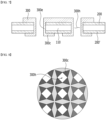
Figs. 5 to 7 are views illustrating a method of manufacturing an electrode for secondary battery according to another embodiment of the present disclosure.Fig. 8 is a plan view illustrating a peripheral state of a hole when viewed from a bottom surface of an electrode current collector in the secondary battery electrode ofFig. 7 . - Referring to
Fig. 5 , theelectrode tab 300 may be overlapped and arranged on theactive material layer 200 to be fused. After that, a notch or a break may be formed in a portion of theelectrode tab 300 in which a hole is to be formed. - Referring to
Fig. 6 , at least onehole 300h may be formed in the electrode for secondary battery in a state in which theactive material layer 200 and theelectrode tab 300 are overlapped with each other. At this time, thehole 300h may be formed by a process of forming the notch or break in the portion of theelectrode tab 300 and then applying pressure using a pin, but is not limited thereto. - In the process of forming the
hole 300h, theelectrode tab 300 on theactive material layer 200 may be extended along the inner wall of thehole 300h. Theextension portion 300e of theelectrode tab 300 may be extended long along the inner wall of thehole 300h passing through theactive material layer 200 and the electrodecurrent collector 110 as well as theelectrode tab 300. - Referring to
Fig. 7 , in order to physically fuse theelectrode tab 300 to theactive material layer 200 and the electrodecurrent collector 110, at least one of the upper and lower portions of the electrode for secondary battery may be pressed. At this time, the trace of theextension portion 300e of theelectrode tab 300 can be bent by the force due to the pressing and can come into contact with an active material layer 200' formed on the bottom surface of the electrodecurrent collector 110 or the bottom surface of the electrodecurrent collector 110. Specifically, theextension portion 300e of theelectrode tab 300 is bent after passing through thehole 300h, and the fixingpart 300c of theelectrode tab 300 may be formed in the bottom surface of the electrodecurrent collector 110 or the active material layer 200' formed on the bottom surface of the electrodecurrent collector 110. That is, theelectrode tab 300 has a structure that passes through thehole 300h and surrounds the active material layers 200 and 200' and the electrodecurrent collector 110, whereby theelectrode tab 300 is fixed and can come into contact with the electrodecurrent collector 110. In the case of the fixing, it may be additionally fixed by including a fixing plate (not shown) that is in contact with the electrodetab fixing part 300c and is coupled to thehole 300h, but is not limited thereto. - Referring to
Fig. 8 , the periphery of thehole 300h viewed from the opposite side of the fusion surface of theelectrode tab 300, the trace of theelectrode tab 300 is bent to form the electrodetab fixing part 300c and fusion in the form of a clip may occur. - The plurality of
holes 300h may be formed in various sizes or shapes. In one example, the plurality ofholes 300h may be formed in a circular, quadrangular, triangular, rhombic, or trapezoidal shape, and the sizes of the plurality ofholes 300h may be the same or different. - Thereby, physical fusion can be realized instead of the ultrasonic fusion method for fusion between the electrode
current collector 110 and theelectrode tab 300. Theelectrode tab 300 can be fused even if there is no non-coating part. The size and number of theholes 300h are not limited, but as the size of theholes 300h is smaller and the number of the holes is larger, the current path increases, which may be advantageous in terms of resistance. -
Fig. 9 is a plan view of an electrode for secondary battery according to another embodiment of the present disclosure.Fig. 10 is a cross-sectional view taken along the cutting line C-C ofFig. 9 . - Referring to
Figs. 9 and 10 , the electrodecurrent collector 110 in the present embodiment includes acoated portion 130 and anuncoated portion 140. Here, in the electrodecurrent collector 110, theuncoated portion 140 is a portion on which theactive material layer 200 is not formed. Theuncoated portion 140 and thecoated portion 130 may be formed on one surface of the electrodecurrent collector 110 by a pattern coating method, and the coated portion 130' may be formed without the uncoated portion on the other surface of the electrodecurrent collector 110. - The
electrode tab 300 may be located on theuncoated portion 140 of the electrodecurrent collector 110. Further, theelectrode tab 300 may be fused to the electrodecurrent collector 110 on theuncoated portion 140 to be fixed to the electrodecurrent collector 110. - The fusion of the
electrode tab 300 according to the present embodiment may be the same as in the method described in the embodiments ofFigs. 5 to 7 . In other words, a plurality of holes are formed in theelectrode tab 300 in a state in which theelectrode tab 300 is overlapped and arranged on the uncoated portion 150, and then the extension portion of theelectrode tab 300 can pass through the hole by pressing. Further, the trace of theelectrode tab 300 is bent, and the electrode tab can be fixed and fused to the active material layer formed in the form of a clip on the bottom surface of the electrode current collector or the bottom surface of the electrode current collector. - According to the present embodiment, a non-coating part is formed only in the fusion portion of the
electrode tab 300, thereby increasing the contact area for current flow. - The width of the
uncoated portion 140 formed on one surface of the electrodecurrent collector 110 is shorter than the width of thecoated portion 130 on one surface or the coated portion 130' on the other surface. As the width of theuncoated portion 140 is shorter, the electrode capacity increases, and the problem of non-uniformity occurring during the patterning process can be solved. - However, the width and length of the
uncoated portion 140 is not limited to the above-mentioned contents, and as long as it is a width for improving electrode performance, it is not limited thereto and may be formed in various lengths. - The electrode for secondary batteries described above can be applied to various secondary batteries. These secondary batteries can be applied to a cylindrical battery in which the electrode assembly is built into in a cylindrical metal can, a prismatic battery in which the electrode assembly is built into a prismatic metal can, and a pouch type battery in which the electrode assembly is built into a pouch type case of an aluminum laminate sheet, but the present disclosure is not limited thereto and can be applied to various secondary batteries that can use for the electrode for secondary battery.
- Although the preferred embodiments of the present disclosure have been described in detail above, the scope of the present disclosure is not limited thereto, and various modifications and improvements made by those skilled in the art using the basic concepts of the present disclosure defined in the following claims also falls within the spirit and scope of the present disclosure.
-
- 100: electrode for secondary battery
- 110: electrode current collector
- 130: coated portion
- 140: uncoated portion
- 200: active material layer
- 300: electrode tab
- 300h: hole
Claims (14)
- An electrode for secondary battery comprising:an electrode current collector containing a coated portion;a first active material layer located on the coated portion; andan electrode tab that is electrically connected to the electrode current collector,wherein the electrode tab is located on one surface of the electrode current collector, at least one hole is formed in the electrode tab, and an extension portion of the electrode tab extending through the hole is in contact with the electrode current collector.
- The electrode for secondary battery according to claim 1, wherein:
the extension portion of the electrode tab is in contact with a side surface of the electrode current collector exposed by the hole. - The electrode for secondary battery according to claim 2, wherein:
the electrode tab is located on the first active material layer while overlapping the first active material layer. - The electrode for secondary battery according to claim 3, wherein:
the electrode current collector has an upper surface on which the first active material layer is located and a bottom surface located on the opposite side of the upper surface, and the extension portion of the electrode tab is bent so as to overlap the bottom surface of the electrode current collector, thereby forming an electrode tab fixing portion. - The electrode for secondary battery according to claim 4,which further comprises a second active material layer located on the bottom surface of the electrode current collector,wherein the electrode tab fixing portion is in contact with the second active material layer.
- The electrode for secondary battery according to claim 2,which further comprises an uncoated portion formed on the same surface as the one surface of the electrode current collector on which the coated portion is formed,wherein the electrode tab is located on the uncoated portion while overlapping the uncoated portion.
- The electrode for secondary battery according to claim 6, wherein:
the electrode current collector has an upper surface on which the first active material layer is located, and a bottom surface located on the opposite side of the upper surface, and the electrode tab is in contact with an upper surface of the electrode current collector in the uncoated portion. - The electrode for secondary battery according to claim 7, wherein:
the extension portion of the electrode tab is bent so as to overlap the bottom surface of the electrode current collector, thereby forming an electrode tab fixing portion. - The electrode for secondary battery according to claim 6, wherein:
a width of the uncoated portion is shorter than a width of the coated portion. - A method of manufacturing an electrode for secondary battery, comprising the steps of:arranging an electrode tab on an electrode current collector so as to overlap each other,forming at least one hole passing through the electrode tab and the electrode current collector,pressing at least one of the upper and lower portions of the electrode including the electrode current collector, andallowing an extension portion of the electrode tab extending along the inner wall of the hole to be bent so as to overlap the bottom surface of the electrode current collector, thereby forming an electrode tab fixing portion.
- The method of manufacturing an electrode for secondary battery according to claim 10,
which further comprises forming a notch or a gap in the electrode tab portion where the hole is formed, before forming a hole in the electrode tab. - The method of manufacturing an electrode for secondary battery according to claim 11, wherein:
the extension portion of the electrode tab is in contact with a side surface of the electrode current collector exposed by the hole. - The method of manufacturing an electrode for secondary battery according to claim 10, wherein:
in the step of forming an electrode tab fixing portion, a trace of the extension portion of the electrode tab is bent by the pressing force and comes into contact with an active material layer formed on the bottom surface of the electrode current collector or the bottom surface of the electrode current collector. - A secondary battery comprising the electrode for secondary battery according to claim 1.
Applications Claiming Priority (2)
| Application Number | Priority Date | Filing Date | Title |
|---|---|---|---|
| KR1020200160316A KR20220072563A (en) | 2020-11-25 | 2020-11-25 | Electrode for secondary battery and method of manufacturing the same |
| PCT/KR2021/017365 WO2022114765A1 (en) | 2020-11-25 | 2021-11-24 | Electrode for secondary battery and method of manufacturing same |
Publications (2)
| Publication Number | Publication Date |
|---|---|
| EP4170815A1 true EP4170815A1 (en) | 2023-04-26 |
| EP4170815A4 EP4170815A4 (en) | 2024-11-20 |
Family
ID=81754617
Family Applications (1)
| Application Number | Title | Priority Date | Filing Date |
|---|---|---|---|
| EP21898591.9A Pending EP4170815A4 (en) | 2020-11-25 | 2021-11-24 | Electrode for secondary battery and method of manufacturing same |
Country Status (6)
| Country | Link |
|---|---|
| US (1) | US20230327298A1 (en) |
| EP (1) | EP4170815A4 (en) |
| JP (1) | JP2023536402A (en) |
| KR (1) | KR20220072563A (en) |
| CN (1) | CN116075976A (en) |
| WO (1) | WO2022114765A1 (en) |
Cited By (1)
| Publication number | Priority date | Publication date | Assignee | Title |
|---|---|---|---|---|
| EP4496024A3 (en) * | 2023-07-10 | 2025-03-26 | Ningde Amperex Technology Limited | Electrode plate assembly, electrode assembly, electrochemical device, electrical device, and electrode plate assembly manufacturing method |
Families Citing this family (1)
| Publication number | Priority date | Publication date | Assignee | Title |
|---|---|---|---|---|
| EP4742311A1 (en) * | 2024-11-12 | 2026-05-13 | Samsung Sdi Co., Ltd. | Electrode and secondary battery |
Family Cites Families (14)
| Publication number | Priority date | Publication date | Assignee | Title |
|---|---|---|---|---|
| JP4850996B2 (en) * | 2000-04-28 | 2012-01-11 | パナソニック株式会社 | Electrode plate unit and battery |
| JP4640354B2 (en) * | 2007-02-26 | 2011-03-02 | ソニー株式会社 | ELECTRODE STRUCTURE AND METHOD FOR MANUFACTURING THE SAME |
| JP2009037894A (en) * | 2007-08-02 | 2009-02-19 | Panasonic Corp | Non-aqueous secondary battery electrode plate, method for producing the same, and non-aqueous secondary battery using the same |
| KR20100114934A (en) * | 2008-06-25 | 2010-10-26 | 파나소닉 주식회사 | Electrode structural body for non-aqueous electrolyte secondary battery, method of manufacture thereof and non-aqueous electrolyte secondary battery |
| KR101156377B1 (en) * | 2009-11-30 | 2012-06-13 | 삼성에스디아이 주식회사 | Secondary battery |
| JP2011233462A (en) * | 2010-04-30 | 2011-11-17 | Sanyo Electric Co Ltd | Battery and manufacturing method thereof and method for joining metal sheet |
| JP2015060626A (en) * | 2013-09-17 | 2015-03-30 | 日立マクセル株式会社 | Lithium ion secondary battery |
| JP6472025B2 (en) * | 2015-02-18 | 2019-02-20 | セイコーインスツル株式会社 | Electrochemical cell |
| JP6429820B2 (en) * | 2016-03-24 | 2018-11-28 | 太陽誘電株式会社 | Electrochemical devices |
| KR102031605B1 (en) * | 2017-01-11 | 2019-10-14 | 주식회사 엘지화학 | Device Comprising Member for Preventing Short-Circuit for Measuring Electrode Potential by Using Three Electrode System |
| JP6867936B2 (en) * | 2017-11-30 | 2021-05-12 | ニチコン株式会社 | Electrolytic capacitors and their manufacturing methods |
| JP7229027B2 (en) * | 2019-01-29 | 2023-02-27 | 三洋電機株式会社 | Secondary battery and manufacturing method thereof |
| KR102733884B1 (en) * | 2019-02-18 | 2024-11-22 | 주식회사 엘지에너지솔루션 | Electrode for secondary battery and manufacturing method thereof |
| KR102812156B1 (en) * | 2019-05-03 | 2025-05-22 | 주식회사 엘지에너지솔루션 | Battery including a bonding structure between a lead tab having plurality of holes and electrode tabs and method of joining electrode tabs and a lead tab of a battery |
-
2020
- 2020-11-25 KR KR1020200160316A patent/KR20220072563A/en active Pending
-
2021
- 2021-11-24 US US18/019,429 patent/US20230327298A1/en active Pending
- 2021-11-24 WO PCT/KR2021/017365 patent/WO2022114765A1/en not_active Ceased
- 2021-11-24 EP EP21898591.9A patent/EP4170815A4/en active Pending
- 2021-11-24 JP JP2023504071A patent/JP2023536402A/en active Pending
- 2021-11-24 CN CN202180057203.2A patent/CN116075976A/en active Pending
Cited By (1)
| Publication number | Priority date | Publication date | Assignee | Title |
|---|---|---|---|---|
| EP4496024A3 (en) * | 2023-07-10 | 2025-03-26 | Ningde Amperex Technology Limited | Electrode plate assembly, electrode assembly, electrochemical device, electrical device, and electrode plate assembly manufacturing method |
Also Published As
| Publication number | Publication date |
|---|---|
| EP4170815A4 (en) | 2024-11-20 |
| KR20220072563A (en) | 2022-06-02 |
| CN116075976A (en) | 2023-05-05 |
| US20230327298A1 (en) | 2023-10-12 |
| JP2023536402A (en) | 2023-08-25 |
| WO2022114765A1 (en) | 2022-06-02 |
Similar Documents
| Publication | Publication Date | Title |
|---|---|---|
| JP6249493B2 (en) | Non-aqueous electrolyte secondary battery | |
| US20190221824A1 (en) | Non-aqueous electrolyte secondary battery | |
| US8404386B2 (en) | Method of manufacturing lithium secondary battery and lithium secondary battery | |
| US8025999B2 (en) | Pouch type lithium rechargeable battery | |
| US8962179B2 (en) | Secondary battery | |
| US20110311877A1 (en) | Metal foil for secondary battery and secondary battery | |
| EP2302717A1 (en) | Electrode assembly for a rechargeable battery | |
| KR102557413B1 (en) | Manufacturing method for lithium metal electrode | |
| US20230327298A1 (en) | Electrode for secondary battery and method of manufacturing the same | |
| US20240347785A1 (en) | Electrode core, battery apparatus, and electronic device | |
| CN113130861B (en) | Active material structure and manufacturing method, electrode structure and secondary battery | |
| JP5250365B2 (en) | Electrode plate for lithium ion secondary battery and lithium ion secondary battery | |
| EP4273982A1 (en) | Jelly-roll electrode assembly and secondary battery comprising same | |
| JP4975901B2 (en) | Battery electrode plate and battery | |
| WO2019059117A1 (en) | Current collector and battery using same | |
| KR20230135529A (en) | Jelly roll type electrode assembly, battery cell including the same, and cylindrical battery | |
| JP2005196974A (en) | Secondary battery | |
| JPH10112322A (en) | Battery | |
| EP4447174A1 (en) | Jelly-roll type electrode assembly, battery cell including same, and cylindrical battery | |
| CN114374000B (en) | A battery and energy storage device | |
| JPH1154112A (en) | Non-aqueous electrolyte secondary battery | |
| CN221783265U (en) | Battery cells with improved safety | |
| KR20130055045A (en) | Electrode assembly, method of manufacturing the same, and battery having the same | |
| JP7431072B2 (en) | Square batteries and electrode groups for square batteries | |
| JP2024113307A (en) | Manufacturing method of power storage device |
Legal Events
| Date | Code | Title | Description |
|---|---|---|---|
| STAA | Information on the status of an ep patent application or granted ep patent |
Free format text: STATUS: THE INTERNATIONAL PUBLICATION HAS BEEN MADE |
|
| PUAI | Public reference made under article 153(3) epc to a published international application that has entered the european phase |
Free format text: ORIGINAL CODE: 0009012 |
|
| STAA | Information on the status of an ep patent application or granted ep patent |
Free format text: STATUS: REQUEST FOR EXAMINATION WAS MADE |
|
| 17P | Request for examination filed |
Effective date: 20230118 |
|
| AK | Designated contracting states |
Kind code of ref document: A1 Designated state(s): AL AT BE BG CH CY CZ DE DK EE ES FI FR GB GR HR HU IE IS IT LI LT LU LV MC MK MT NL NO PL PT RO RS SE SI SK SM TR |
|
| DAV | Request for validation of the european patent (deleted) | ||
| DAX | Request for extension of the european patent (deleted) | ||
| A4 | Supplementary search report drawn up and despatched |
Effective date: 20241022 |
|
| RIC1 | Information provided on ipc code assigned before grant |
Ipc: H01M 50/536 20210101ALI20241016BHEP Ipc: H01M 50/533 20210101AFI20241016BHEP |
|
| STAA | Information on the status of an ep patent application or granted ep patent |
Free format text: STATUS: EXAMINATION IS IN PROGRESS |
|
| 17Q | First examination report despatched |
Effective date: 20250721 |