EP4170812A1 - Lithium-ionen-zelle - Google Patents
Lithium-ionen-zelle Download PDFInfo
- Publication number
- EP4170812A1 EP4170812A1 EP21203827.7A EP21203827A EP4170812A1 EP 4170812 A1 EP4170812 A1 EP 4170812A1 EP 21203827 A EP21203827 A EP 21203827A EP 4170812 A1 EP4170812 A1 EP 4170812A1
- Authority
- EP
- European Patent Office
- Prior art keywords
- lithium
- electrolyte
- cell
- electrode material
- current collector
- Prior art date
- Legal status (The legal status is an assumption and is not a legal conclusion. Google has not performed a legal analysis and makes no representation as to the accuracy of the status listed.)
- Pending
Links
Images



Classifications
-
- H—ELECTRICITY
- H01—ELECTRIC ELEMENTS
- H01M—PROCESSES OR MEANS, e.g. BATTERIES, FOR THE DIRECT CONVERSION OF CHEMICAL ENERGY INTO ELECTRICAL ENERGY
- H01M10/00—Secondary cells; Manufacture thereof
- H01M10/05—Accumulators with non-aqueous electrolyte
- H01M10/052—Li-accumulators
- H01M10/0525—Rocking-chair batteries, i.e. batteries with lithium insertion or intercalation in both electrodes; Lithium-ion batteries
-
- H—ELECTRICITY
- H01—ELECTRIC ELEMENTS
- H01M—PROCESSES OR MEANS, e.g. BATTERIES, FOR THE DIRECT CONVERSION OF CHEMICAL ENERGY INTO ELECTRICAL ENERGY
- H01M10/00—Secondary cells; Manufacture thereof
- H01M10/05—Accumulators with non-aqueous electrolyte
- H01M10/056—Accumulators with non-aqueous electrolyte characterised by the materials used as electrolytes, e.g. mixed inorganic/organic electrolytes
- H01M10/0564—Accumulators with non-aqueous electrolyte characterised by the materials used as electrolytes, e.g. mixed inorganic/organic electrolytes the electrolyte being constituted of organic materials only
- H01M10/0566—Liquid materials
- H01M10/0567—Liquid materials characterised by the additives
-
- H—ELECTRICITY
- H01—ELECTRIC ELEMENTS
- H01M—PROCESSES OR MEANS, e.g. BATTERIES, FOR THE DIRECT CONVERSION OF CHEMICAL ENERGY INTO ELECTRICAL ENERGY
- H01M10/00—Secondary cells; Manufacture thereof
- H01M10/05—Accumulators with non-aqueous electrolyte
- H01M10/056—Accumulators with non-aqueous electrolyte characterised by the materials used as electrolytes, e.g. mixed inorganic/organic electrolytes
- H01M10/0564—Accumulators with non-aqueous electrolyte characterised by the materials used as electrolytes, e.g. mixed inorganic/organic electrolytes the electrolyte being constituted of organic materials only
- H01M10/0566—Liquid materials
- H01M10/0568—Liquid materials characterised by the solutes
-
- H—ELECTRICITY
- H01—ELECTRIC ELEMENTS
- H01M—PROCESSES OR MEANS, e.g. BATTERIES, FOR THE DIRECT CONVERSION OF CHEMICAL ENERGY INTO ELECTRICAL ENERGY
- H01M10/00—Secondary cells; Manufacture thereof
- H01M10/05—Accumulators with non-aqueous electrolyte
- H01M10/056—Accumulators with non-aqueous electrolyte characterised by the materials used as electrolytes, e.g. mixed inorganic/organic electrolytes
- H01M10/0564—Accumulators with non-aqueous electrolyte characterised by the materials used as electrolytes, e.g. mixed inorganic/organic electrolytes the electrolyte being constituted of organic materials only
- H01M10/0566—Liquid materials
- H01M10/0569—Liquid materials characterised by the solvents
-
- H—ELECTRICITY
- H01—ELECTRIC ELEMENTS
- H01M—PROCESSES OR MEANS, e.g. BATTERIES, FOR THE DIRECT CONVERSION OF CHEMICAL ENERGY INTO ELECTRICAL ENERGY
- H01M10/00—Secondary cells; Manufacture thereof
- H01M10/05—Accumulators with non-aqueous electrolyte
- H01M10/058—Construction or manufacture
- H01M10/0583—Construction or manufacture of accumulators with folded construction elements except wound ones, i.e. folded positive or negative electrodes or separators, e.g. with "Z"-shaped electrodes or separators
-
- H—ELECTRICITY
- H01—ELECTRIC ELEMENTS
- H01M—PROCESSES OR MEANS, e.g. BATTERIES, FOR THE DIRECT CONVERSION OF CHEMICAL ENERGY INTO ELECTRICAL ENERGY
- H01M4/00—Electrodes
- H01M4/02—Electrodes composed of, or comprising, active material
- H01M4/13—Electrodes for accumulators with non-aqueous electrolyte, e.g. for lithium-accumulators; Processes of manufacture thereof
- H01M4/131—Electrodes based on mixed oxides or hydroxides, or on mixtures of oxides or hydroxides, e.g. LiCoOx
-
- H—ELECTRICITY
- H01—ELECTRIC ELEMENTS
- H01M—PROCESSES OR MEANS, e.g. BATTERIES, FOR THE DIRECT CONVERSION OF CHEMICAL ENERGY INTO ELECTRICAL ENERGY
- H01M4/00—Electrodes
- H01M4/02—Electrodes composed of, or comprising, active material
- H01M4/36—Selection of substances as active materials, active masses, active liquids
- H01M4/48—Selection of substances as active materials, active masses, active liquids of inorganic oxides or hydroxides
- H01M4/485—Selection of substances as active materials, active masses, active liquids of inorganic oxides or hydroxides of mixed oxides or hydroxides for inserting or intercalating light metals, e.g. LiTi2O4 or LiTi2OxFy
-
- H—ELECTRICITY
- H01—ELECTRIC ELEMENTS
- H01M—PROCESSES OR MEANS, e.g. BATTERIES, FOR THE DIRECT CONVERSION OF CHEMICAL ENERGY INTO ELECTRICAL ENERGY
- H01M4/00—Electrodes
- H01M4/02—Electrodes composed of, or comprising, active material
- H01M4/36—Selection of substances as active materials, active masses, active liquids
- H01M4/48—Selection of substances as active materials, active masses, active liquids of inorganic oxides or hydroxides
- H01M4/50—Selection of substances as active materials, active masses, active liquids of inorganic oxides or hydroxides of manganese
- H01M4/505—Selection of substances as active materials, active masses, active liquids of inorganic oxides or hydroxides of manganese of mixed oxides or hydroxides containing manganese for inserting or intercalating light metals, e.g. LiMn2O4 or LiMn2OxFy
-
- H—ELECTRICITY
- H01—ELECTRIC ELEMENTS
- H01M—PROCESSES OR MEANS, e.g. BATTERIES, FOR THE DIRECT CONVERSION OF CHEMICAL ENERGY INTO ELECTRICAL ENERGY
- H01M4/00—Electrodes
- H01M4/02—Electrodes composed of, or comprising, active material
- H01M4/62—Selection of inactive substances as ingredients for active masses, e.g. binders, fillers
- H01M4/621—Binders
- H01M4/622—Binders being polymers
-
- H—ELECTRICITY
- H01—ELECTRIC ELEMENTS
- H01M—PROCESSES OR MEANS, e.g. BATTERIES, FOR THE DIRECT CONVERSION OF CHEMICAL ENERGY INTO ELECTRICAL ENERGY
- H01M4/00—Electrodes
- H01M4/02—Electrodes composed of, or comprising, active material
- H01M4/62—Selection of inactive substances as ingredients for active masses, e.g. binders, fillers
- H01M4/624—Electric conductive fillers
- H01M4/625—Carbon or graphite
-
- H—ELECTRICITY
- H01—ELECTRIC ELEMENTS
- H01M—PROCESSES OR MEANS, e.g. BATTERIES, FOR THE DIRECT CONVERSION OF CHEMICAL ENERGY INTO ELECTRICAL ENERGY
- H01M4/00—Electrodes
- H01M4/02—Electrodes composed of, or comprising, active material
- H01M4/64—Carriers or collectors
- H01M4/66—Selection of materials
- H01M4/661—Metal or alloys, e.g. alloy coatings
-
- H—ELECTRICITY
- H01—ELECTRIC ELEMENTS
- H01M—PROCESSES OR MEANS, e.g. BATTERIES, FOR THE DIRECT CONVERSION OF CHEMICAL ENERGY INTO ELECTRICAL ENERGY
- H01M4/00—Electrodes
- H01M4/02—Electrodes composed of, or comprising, active material
- H01M4/64—Carriers or collectors
- H01M4/66—Selection of materials
- H01M4/661—Metal or alloys, e.g. alloy coatings
- H01M4/662—Alloys
-
- H—ELECTRICITY
- H01—ELECTRIC ELEMENTS
- H01M—PROCESSES OR MEANS, e.g. BATTERIES, FOR THE DIRECT CONVERSION OF CHEMICAL ENERGY INTO ELECTRICAL ENERGY
- H01M4/00—Electrodes
- H01M4/02—Electrodes composed of, or comprising, active material
- H01M4/64—Carriers or collectors
- H01M4/70—Carriers or collectors characterised by shape or form
-
- H—ELECTRICITY
- H01—ELECTRIC ELEMENTS
- H01M—PROCESSES OR MEANS, e.g. BATTERIES, FOR THE DIRECT CONVERSION OF CHEMICAL ENERGY INTO ELECTRICAL ENERGY
- H01M4/00—Electrodes
- H01M4/02—Electrodes composed of, or comprising, active material
- H01M4/64—Carriers or collectors
- H01M4/70—Carriers or collectors characterised by shape or form
- H01M4/72—Grids
- H01M4/74—Meshes or woven material; Expanded metal
- H01M4/742—Meshes or woven material; Expanded metal perforated material
-
- H—ELECTRICITY
- H01—ELECTRIC ELEMENTS
- H01M—PROCESSES OR MEANS, e.g. BATTERIES, FOR THE DIRECT CONVERSION OF CHEMICAL ENERGY INTO ELECTRICAL ENERGY
- H01M50/00—Constructional details or processes of manufacture of the non-active parts of electrochemical cells other than fuel cells, e.g. hybrid cells
- H01M50/40—Separators; Membranes; Diaphragms; Spacing elements inside cells
- H01M50/46—Separators, membranes or diaphragms characterised by their combination with electrodes
-
- H—ELECTRICITY
- H01—ELECTRIC ELEMENTS
- H01M—PROCESSES OR MEANS, e.g. BATTERIES, FOR THE DIRECT CONVERSION OF CHEMICAL ENERGY INTO ELECTRICAL ENERGY
- H01M50/00—Constructional details or processes of manufacture of the non-active parts of electrochemical cells other than fuel cells, e.g. hybrid cells
- H01M50/50—Current conducting connections for cells or batteries
- H01M50/531—Electrode connections inside a battery casing
-
- H—ELECTRICITY
- H01—ELECTRIC ELEMENTS
- H01M—PROCESSES OR MEANS, e.g. BATTERIES, FOR THE DIRECT CONVERSION OF CHEMICAL ENERGY INTO ELECTRICAL ENERGY
- H01M4/00—Electrodes
- H01M4/02—Electrodes composed of, or comprising, active material
- H01M2004/021—Physical characteristics, e.g. porosity, surface area
-
- H—ELECTRICITY
- H01—ELECTRIC ELEMENTS
- H01M—PROCESSES OR MEANS, e.g. BATTERIES, FOR THE DIRECT CONVERSION OF CHEMICAL ENERGY INTO ELECTRICAL ENERGY
- H01M4/00—Electrodes
- H01M4/02—Electrodes composed of, or comprising, active material
- H01M2004/026—Electrodes composed of, or comprising, active material characterised by the polarity
- H01M2004/027—Negative electrodes
-
- H—ELECTRICITY
- H01—ELECTRIC ELEMENTS
- H01M—PROCESSES OR MEANS, e.g. BATTERIES, FOR THE DIRECT CONVERSION OF CHEMICAL ENERGY INTO ELECTRICAL ENERGY
- H01M4/00—Electrodes
- H01M4/02—Electrodes composed of, or comprising, active material
- H01M2004/026—Electrodes composed of, or comprising, active material characterised by the polarity
- H01M2004/028—Positive electrodes
-
- H—ELECTRICITY
- H01—ELECTRIC ELEMENTS
- H01M—PROCESSES OR MEANS, e.g. BATTERIES, FOR THE DIRECT CONVERSION OF CHEMICAL ENERGY INTO ELECTRICAL ENERGY
- H01M2300/00—Electrolytes
- H01M2300/0017—Non-aqueous electrolytes
- H01M2300/0025—Organic electrolyte
- H01M2300/0028—Organic electrolyte characterised by the solvent
- H01M2300/0037—Mixture of solvents
-
- H—ELECTRICITY
- H01—ELECTRIC ELEMENTS
- H01M—PROCESSES OR MEANS, e.g. BATTERIES, FOR THE DIRECT CONVERSION OF CHEMICAL ENERGY INTO ELECTRICAL ENERGY
- H01M2300/00—Electrolytes
- H01M2300/0017—Non-aqueous electrolytes
- H01M2300/0025—Organic electrolyte
- H01M2300/0028—Organic electrolyte characterised by the solvent
- H01M2300/0037—Mixture of solvents
- H01M2300/004—Three solvents
-
- Y—GENERAL TAGGING OF NEW TECHNOLOGICAL DEVELOPMENTS; GENERAL TAGGING OF CROSS-SECTIONAL TECHNOLOGIES SPANNING OVER SEVERAL SECTIONS OF THE IPC; TECHNICAL SUBJECTS COVERED BY FORMER USPC CROSS-REFERENCE ART COLLECTIONS [XRACs] AND DIGESTS
- Y02—TECHNOLOGIES OR APPLICATIONS FOR MITIGATION OR ADAPTATION AGAINST CLIMATE CHANGE
- Y02E—REDUCTION OF GREENHOUSE GAS [GHG] EMISSIONS, RELATED TO ENERGY GENERATION, TRANSMISSION OR DISTRIBUTION
- Y02E60/00—Enabling technologies; Technologies with a potential or indirect contribution to GHG emissions mitigation
- Y02E60/10—Energy storage using batteries
-
- Y—GENERAL TAGGING OF NEW TECHNOLOGICAL DEVELOPMENTS; GENERAL TAGGING OF CROSS-SECTIONAL TECHNOLOGIES SPANNING OVER SEVERAL SECTIONS OF THE IPC; TECHNICAL SUBJECTS COVERED BY FORMER USPC CROSS-REFERENCE ART COLLECTIONS [XRACs] AND DIGESTS
- Y02—TECHNOLOGIES OR APPLICATIONS FOR MITIGATION OR ADAPTATION AGAINST CLIMATE CHANGE
- Y02P—CLIMATE CHANGE MITIGATION TECHNOLOGIES IN THE PRODUCTION OR PROCESSING OF GOODS
- Y02P70/00—Climate change mitigation technologies in the production process for final industrial or consumer products
- Y02P70/50—Manufacturing or production processes characterised by the final manufactured product
Definitions
- the invention described below relates to a secondary lithium-ion cell.
- the discharge is reversible, i.e. if there is the possibility of reversing the conversion of chemical energy into electrical energy during the discharge and thus recharging the cell, this is referred to as a secondary cell.
- Secondary lithium-ion cells are used for many applications today because they can provide high currents and are characterized by a comparatively high energy density. They are based on the use of lithium, which can migrate back and forth between the electrodes of the cell in the form of ions.
- the negative electrode and the positive electrode of a lithium-ion cell are usually formed by what are known as composite electrodes, which also include electrochemically inactive components in addition to electrochemically active components.
- the composite electrodes are combined with one or more separators to form a composite body.
- the electrodes and separators are connected to one another, usually under pressure, possibly also by lamination or by gluing.
- the basic functionality of the cell can then be established by impregnating the composite with the electrolyte.
- the direct connection of the contact sheet to the current collectors of the electrodes can ensure excellent heat dissipation properties, which will be explained below.
- LMO has long been known as an electrode material for the positive electrodes of lithium-ion batteries. It has a spinel structure similar to that of the naturally occurring mineral MgAl 2 O 4 .
- the percentages relate to the dry mass of the electrode material, i.e. to the electrode material excluding the electrolyte.
- the layer of negative electrode material on the anode current collector has a thickness in the range of 20 ⁇ m to 300 ⁇ m.
- the solid electrolyte is preferably a polymer solid electrolyte based on a polymer-conductive salt complex, which is present in a single phase without any liquid component.
- a polymer solid electrolyte can have polyacrylic acid (PAA), polyethylene glycol (PEG) or polymethyl methacrylate (PMMA) as the polymer matrix.
- Lithium conductive salts such as lithium bis-(trifluoromethane)sulfonylimide (LiTFSI), lithium hexafluorophosphate (LiPF 6 ) and lithium tetrafluoroborate (LiBF 4 ) can be present dissolved in these.
- the cell comprises a liquid electrolyte which consists of a solvent or solvent mixture and a conductive salt containing lithium ions and with which the separator is impregnated.
- the cell comprises an electrolyte which is a conductive salt from the group with tetraethylammonium tetrafluoroborate (Et4NBF4), lithium hexafluorophosphate (LiPF6), lithium hexafluoroarsenate (LiAsF6), lithium tetrafluoroborate (LiBF4), lithium perchlorate (LiClO 4 ), lithium bis(oxalato)borate (LiB(C 2 O 4 ) 2 ) and LiP(C 6 H 4 O 2 ) 3 .
- Et4NBF4 tetraethylammonium tetrafluoroborate
- LiPF6 lithium hexafluorophosphate
- LiAsF6 lithium hexafluoroarsenate
- LiBF4 lithium tetrafluoroborate
- LiClO 4 lithium perchlorate
- LiB(C 2 O 4 ) 2 lithium bis(oxal
- the conductive salt is preferably contained in the electrolyte in a proportion of 0.5M to 5M, in particular 2M.
- the electrolyte according to the first variant has proven to be particularly advantageous.
- the solvent acetonitrile is often used in the condenser section for EDLCs. It is generally not used for lithium-ion cells because it is not stable under the usual electrochemical conditions. However, no problems arose in this regard. On the contrary, it could be shown that the cell according to the invention showed excellent cyclability with this electrolyte.
- the separator can therefore preferably also be a plastic film or a fleece or a woven fabric or some other electrically insulating sheetlike structure which is coated with the particulate filling material.
- features a. to c. or the features immediately above a. and b. and d. or the features immediately above a. and b. and e. are realized in combination with each other.
- aluminum oxide (Al 2 O 3 ), titanium oxide (TiO 2 ) and silicon dioxide (SiO 2 ) are particularly preferred as coating materials.
- the current collectors of the cell according to the invention serve to electrically contact electrochemically active components contained in the respective electrode material over as large an area as possible.
- the current collectors preferably consist of a metal or are at least metallized on the surface. Suitable metals for the anode current collector are, for example, copper or nickel or other electrically conductive materials, in particular copper and nickel alloys or metals coated with nickel. In principle, stainless steel is also an option. Aluminum or other electrically conductive materials, including aluminum alloys, are suitable as the metal for the cathode current collector. Stainless steel, for example type 1.4404, can also be used here.
- the anode current collector and/or the cathode current collector is preferably a metal foil with a thickness in the range from 4 ⁇ m to 30 ⁇ m, in particular a strip-shaped metal foil with a thickness in the range from 4 ⁇ m to 30 ⁇ m.
- the use of aluminum current collectors on the anode side which results from the use of LTO/LMO electrochemistry, has advantages over the use of, for example, copper-based current collectors. Since aluminum is lighter than copper, the energy density of the cell can be increased significantly. In addition, it has been found that cells according to the invention with aluminum foils as current collectors and LTO-based anodes are very stable against deep discharge. The tendency to form dendrites appears to be significantly reduced.
- the openings are made in the strip-shaped main area by means of a laser.
- the preferred configurations of the current collector provided with the openings described above are independently applicable to the anode current collector and the cathode current collector.
- the metal disc lies flat on the first longitudinal edge, resulting in a line-like contact zone which, in the case of the spirally wound electrodes, has a spiral course.
- the first longitudinal edge and thus also the edge strip can be bent over or deformed.
- the closure variant with the ring-shaped seal made of the electrically insulating material means that the contact plate is electrically insulated from the tubular housing part. It forms an electrical pole of the cell.
- the tubular housing part and the contact plate have the same polarity.
- the contact sheet can be part of the cover assembly mentioned, which, in addition to the contact sheet, includes the metal disk mentioned and optionally other individual parts.
- the contact plate and the metal disk are preferably in contact with one another directly or via an electrical conductor.
- the contact plate is the metal disc mentioned.
- the one of the edge strips may be bent or deformed through contact with the at least one ridge.
- the contact sheet can have recesses such as holes or gaps, which serve the purpose of simplifying the distribution of the electrolyte during dosing and promoting the escape of gases formed during formation or as a result of misuse or defects from the inside of the coil.
- the contact plate and the metal disk are preferably in direct contact with one another. In this case, they are particularly preferably fixed to one another by welding or soldering.
- an aluminum, copper or nickel alloy is mentioned in connection with the housing materials, this preferably means an alloy that has a content of at least 70% by weight, preferably at least 90% by weight, of the respective base metal aluminum , copper or nickel.
- electrically insulating material is to be interpreted broadly in the present case. In principle, it includes any electrically insulating material, including in particular said plastics.
- the support material is applied directly next to the preferably strip-shaped main areas in the form of a strip or a line, but does not completely cover the free areas, so that the metal of the respective current collector is exposed directly along the longitudinal edge.
- the nominal capacity of a button cell designed as a lithium-ion cell according to the invention is usually up to 1500 mAh.
- the nominal capacity is preferably in the range from 100 mAh to 1000 mAh, particularly preferably in the range from 100 to 800 mAh.
- the cell according to the invention is particularly preferably a cylindrical round cell.
- Cylindrical round cells have a height that is greater than their diameter. They are particularly suitable for the applications mentioned above with a high energy requirement, for example in the automotive sector or for e-bikes or for power tools.
- the nominal capacity of the cylindrical round cell according to the invention designed as a lithium-ion cell is preferably up to 90,000 mAh.
- the cell in one embodiment as a lithium-ion cell preferably has a nominal capacity in the range from 1500 mAh to 7000 mAh, particularly preferably in the range from 3000 to 5500 mAh.
- the cell in one embodiment as a lithium-ion cell preferably has a nominal capacity in the range from 1000 mAh to 5000 mAh, particularly preferably in the range from 2000 to 4000 mAh.
- the free edge strip which extends along the first longitudinal edge and which is not loaded with the electrode material preferably has a width of not more than 5000 ⁇ m.
- FIG. 1 and 2 illustrate the design of a current collector 115 that can be used in a cell according to the invention. At 2 it is a cut along S 1 .
- the current collector 115 includes a plurality of through holes 211, which are rectangular holes.
- the area 115x is characterized by the openings 211, whereas there are no openings in the area 115z along the longitudinal edge 115a.
- the current collector 115 therefore has a significantly lower basis weight in area 115x than in area 115z.
- Closure elements according to the present invention which can be used within the framework of the above-described housing variant with two covers, can preferably also be designed according to embodiments A to H.
- the spirally wound electrode-separator assembly 104 is aligned axially, so that its winding jacket 104a rests against the inside of the tubular housing part 101 .
- the edge strip 121 of the anode current collector that is not covered with electrode material emerges from the upper end face 104b of the electrode-separator composite 104 designed as a coil. This is welded or soldered directly to the underside of the contact sheet 113 .
- the cell 100 shown includes a lid assembly analogous to that shown in Figure 1B, but with one difference.
- the metal disc 111 resting on the pole cover 112 is not used for contacting the anode current collectors.
- it comprises the metal contact sheet 113.
- This has two sides, one of which points in the direction of the metal disk 111, even lies flat against it, and is connected to the metal disk 111 by welding or soldering.
- the free edge strip 121 of the anode current collector emerges from the upper end face 104b of the electrode-separator composite 104 designed as a coil. This is in direct contact with the underside of the contact sheet 113 and is welded or soldered to the underside of the contact sheet 113 .
- the free edge strip 121 of the anode current collector emerges from the upper end face 104b of the electrode-separator composite 104 designed as a coil.
- the free edge strip 117 of the cathode current collector emerges from the underlying end face 104c of the electrode-separator composite 104 designed as a coil.
- the cell 100 comprises the tubular and hollow-cylindrical metallic housing part 101, which has two terminal openings.
- the opening at the top is closed by the metal disk 111, which is arranged in the tubular housing part 101 in such a way that its edge 111a rests against the inside 101b of the tubular housing part 101 along a circumferential contact zone.
- the edge 111a of the metal disc 111 is connected to the tubular housing part 101 via a circumferential welded or soldered seam.
- the metal disc 111 is part of a cover assembly 110 which, in addition to the metal disc 111, includes the metal contact plate 113 and the pole pin 108.
- the metal contact plate 113 comprises two sides, one of which, in the picture the one at the top, points in the direction of the metal disc 111 .
- the longitudinal edge 115a is in direct contact with the other side of the contact plate 113, here the side lying underneath.
- the longitudinal edge 115a is connected to the contact plate 113 by welding or soldering.
- the pole pin 108 is welded or soldered to the contact plate 113 and led out of the housing of the cell 100 through a central opening in the metal disk 111 .
- the cover assembly 110 also includes the insulating means 103, which electrically insulates the pole pin 108 and thus also the contact sheet 113, which is welded or soldered to the pole pin, from the metal disk 111.
- the longitudinal edge 125a of the cathode current collector is in direct contact with the inner (upper) side of the contact plate 113 .
- the longitudinal edge 125a is connected to the closure element 145 through Welding or soldering connected.
- the welding can be effected through the metal disk of the closure element 145 by means of a laser, for example.
- edge 111a corresponds to the edge of the cover assembly and is connected to the tubular housing part 101 via a peripheral welded or soldered seam.
- the edge 101a of the tubular housing part 101 is bent over the edge 111a of the metal disk 111 radially (here by approximately 90°) inwards.
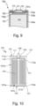
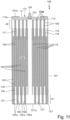
- the electrode-separator assembly 104 is present in the form of a cylindrical coil with two end faces, between which the peripheral coil jacket extends, which bears against the inside of the hollow-cylindrical housing part 101 . It is composed of a positive electrode and a negative electrode and the separators 118 and 119 each formed in a belt shape and spirally wound.
- the two end faces of the electrode-separator assembly 104 are formed by the longitudinal edges of the separators 118 and 119 .
- the current collectors 115 and 125 both of which are made of aluminum, protrude from these end faces.
- the corresponding projections are denoted by d1 and d2.
- the anode current collector 115 emerges from the upper face of the electrode-separator combination 104 and the cathode current collector 125 emerges from the lower face.
- the cathode current collector 125 is loaded with a layer of a positive electrode material 123 in a strip-shaped main area.
- the anode current collector 115 has an edge strip 117 which extends along its longitudinal edge 115a and which is not loaded with the electrode material 155 . Instead, a coating 165 made of a ceramic supporting material is applied here, which stabilizes the current collector in this area.
- the cathode current collector 125 has an edge strip 121 extending along its longitudinal edge 125a and which is not loaded with the electrode material 123. Instead, the coating 165 made of the ceramic support material is also applied here.
- the pole pin 108 is welded or soldered to the contact plate 113 and led out of the housing of the cell 100 through a central opening in the metal disk 111 .
- the cover assembly 110 also includes the insulating means 103, which electrically insulates the pole pin 108 and thus also the contact plate 113, which is welded or soldered to the pole pin, from the metal disk 111. Only the metal disk 111 is in direct and therefore also in electrical contact with the housing cup 107.
- the pole pin 108 and the contact plate 113 are insulated from the housing cup.
- the electrode-separator assembly 104 can comprise, for example, a positive electrode made of 95% by weight of LMO, 2% by weight of an electrode binder and 3% by weight of carbon black as a conductive agent.
- the anode 101 may include, for example, a negative electrode made of 95% by weight of LTO, 2% by weight of an electrode binder, and 3% by weight of carbon black as a conductive agent.
- a 2 M solution of lithium tetrafluoroborate (LiBF 4 ) in acetonitrile can be used as the electrolyte.
Landscapes
- Chemical & Material Sciences (AREA)
- General Chemical & Material Sciences (AREA)
- Chemical Kinetics & Catalysis (AREA)
- Electrochemistry (AREA)
- Engineering & Computer Science (AREA)
- Inorganic Chemistry (AREA)
- Manufacturing & Machinery (AREA)
- General Physics & Mathematics (AREA)
- Condensed Matter Physics & Semiconductors (AREA)
- Physics & Mathematics (AREA)
- Materials Engineering (AREA)
- Secondary Cells (AREA)
- Cell Electrode Carriers And Collectors (AREA)
- Connection Of Batteries Or Terminals (AREA)
- Battery Electrode And Active Subsutance (AREA)
Priority Applications (6)
| Application Number | Priority Date | Filing Date | Title |
|---|---|---|---|
| EP21203827.7A EP4170812A1 (de) | 2021-10-20 | 2021-10-20 | Lithium-ionen-zelle |
| CN202280070345.7A CN118176622A (zh) | 2021-10-20 | 2022-10-13 | 锂离子电芯 |
| PCT/EP2022/078566 WO2023066791A1 (de) | 2021-10-20 | 2022-10-13 | Lithium-ionen-zelle |
| US18/702,806 US20250233195A1 (en) | 2021-10-20 | 2022-10-13 | Lithium-ion cell |
| KR1020247015502A KR20240089536A (ko) | 2021-10-20 | 2022-10-13 | 리튬 이온 전지 |
| JP2024523592A JP2024540930A (ja) | 2021-10-20 | 2022-10-13 | リチウムイオンセル |
Applications Claiming Priority (1)
| Application Number | Priority Date | Filing Date | Title |
|---|---|---|---|
| EP21203827.7A EP4170812A1 (de) | 2021-10-20 | 2021-10-20 | Lithium-ionen-zelle |
Publications (1)
| Publication Number | Publication Date |
|---|---|
| EP4170812A1 true EP4170812A1 (de) | 2023-04-26 |
Family
ID=78332703
Family Applications (1)
| Application Number | Title | Priority Date | Filing Date |
|---|---|---|---|
| EP21203827.7A Pending EP4170812A1 (de) | 2021-10-20 | 2021-10-20 | Lithium-ionen-zelle |
Country Status (6)
| Country | Link |
|---|---|
| US (1) | US20250233195A1 (https=) |
| EP (1) | EP4170812A1 (https=) |
| JP (1) | JP2024540930A (https=) |
| KR (1) | KR20240089536A (https=) |
| CN (1) | CN118176622A (https=) |
| WO (1) | WO2023066791A1 (https=) |
Families Citing this family (1)
| Publication number | Priority date | Publication date | Assignee | Title |
|---|---|---|---|---|
| DE102023127572B3 (de) | 2023-10-10 | 2024-05-08 | Dr. Ing. H.C. F. Porsche Aktiengesellschaft | Verfahren zum Herstellen einer Rundzelle einer Traktionsbatterie |
Citations (5)
| Publication number | Priority date | Publication date | Assignee | Title |
|---|---|---|---|---|
| JP2004119330A (ja) | 2002-09-30 | 2004-04-15 | Sanyo Electric Co Ltd | 二次電池及びその製造方法 |
| WO2017215900A1 (de) | 2016-06-16 | 2017-12-21 | Varta Microbattery Gmbh | Elektrochemische zelle mit optimiertem innenwiderstand |
| US20180062147A1 (en) * | 2016-08-26 | 2018-03-01 | Toyota Jidosha Kabushiki Kaisha | Lithium ion secondary battery and battery pack |
| US20200194741A1 (en) * | 2017-11-07 | 2020-06-18 | Kabushiki Kaisha Toshiba | Battery and battery pack |
| EP3916870A1 (de) * | 2020-05-29 | 2021-12-01 | VARTA Microbattery GmbH | Energiespeicherelement mit prismatischem gehäuse |
-
2021
- 2021-10-20 EP EP21203827.7A patent/EP4170812A1/de active Pending
-
2022
- 2022-10-13 KR KR1020247015502A patent/KR20240089536A/ko active Pending
- 2022-10-13 WO PCT/EP2022/078566 patent/WO2023066791A1/de not_active Ceased
- 2022-10-13 CN CN202280070345.7A patent/CN118176622A/zh active Pending
- 2022-10-13 JP JP2024523592A patent/JP2024540930A/ja active Pending
- 2022-10-13 US US18/702,806 patent/US20250233195A1/en active Pending
Patent Citations (5)
| Publication number | Priority date | Publication date | Assignee | Title |
|---|---|---|---|---|
| JP2004119330A (ja) | 2002-09-30 | 2004-04-15 | Sanyo Electric Co Ltd | 二次電池及びその製造方法 |
| WO2017215900A1 (de) | 2016-06-16 | 2017-12-21 | Varta Microbattery Gmbh | Elektrochemische zelle mit optimiertem innenwiderstand |
| US20180062147A1 (en) * | 2016-08-26 | 2018-03-01 | Toyota Jidosha Kabushiki Kaisha | Lithium ion secondary battery and battery pack |
| US20200194741A1 (en) * | 2017-11-07 | 2020-06-18 | Kabushiki Kaisha Toshiba | Battery and battery pack |
| EP3916870A1 (de) * | 2020-05-29 | 2021-12-01 | VARTA Microbattery GmbH | Energiespeicherelement mit prismatischem gehäuse |
Non-Patent Citations (3)
| Title |
|---|
| J.B. GOODENOUGH, JOURNAL OF POWER SOURCES, vol. 174, 2007, pages 996 - 1000 |
| LIN ET AL., JOURNAL OF POWER SOURCES, vol. 248, 2014, pages 1034 - 1041 |
| ZAGHIB ET AL., MATERIALS, vol. 6, 2013, pages 1028 - 1049 |
Also Published As
| Publication number | Publication date |
|---|---|
| CN118176622A (zh) | 2024-06-11 |
| US20250233195A1 (en) | 2025-07-17 |
| WO2023066791A1 (de) | 2023-04-27 |
| JP2024540930A (ja) | 2024-11-06 |
| KR20240089536A (ko) | 2024-06-20 |
Similar Documents
| Publication | Publication Date | Title |
|---|---|---|
| EP3916877A1 (de) | Energiespeicherzelle und herstellungsverfahren | |
| WO2022034156A1 (de) | Energiespeicherzelle und herstellungsverfahren | |
| EP3916829A1 (de) | Lithium-ionen-zelle mit hoher spezifischer energiedichte | |
| WO2022063632A1 (de) | Energiespeicherzelle | |
| WO2022048969A1 (de) | Energiespeicherzelle | |
| EP4158712B1 (de) | Lithium-ionen-zelle mit hoher spezifischer energiedichte | |
| WO2022058342A1 (de) | Lithium-ionen-zelle mit hoher spezifischer energiedichte | |
| EP4169105A1 (de) | Lithium-ionen-zelle mit hoher spezifischer energiedichte | |
| EP3916870A1 (de) | Energiespeicherelement mit prismatischem gehäuse | |
| EP4333165A2 (de) | Energiespeicherelement, deckelbaugruppe und herstellungsverfahren | |
| EP3916868A1 (de) | Energiespeicherzelle und herstellungsverfahren | |
| EP4437614A1 (de) | Energiespeicherzelle, verbund aus energiespeicherzellen und herstellungsverfahren | |
| EP4135088A1 (de) | Energiespeicherelement, verbund aus energiespeicherelementen und herstellungsverfahren | |
| WO2023066791A1 (de) | Lithium-ionen-zelle | |
| EP4197051B1 (de) | Energiespeicherzelle mit hoher spezifischer energiedichte | |
| EP4162554A1 (de) | Lithium-ionen-zelle mit hoher spezifischer energiedichte | |
| EP4164048A1 (de) | Energiespeicherelement und herstellungsverfahren | |
| EP4539180A1 (de) | Energiespeicherelement | |
| WO2023016769A1 (de) | Energiespeicherelement, verbund aus energiespeicherelementen und herstellungsverfahren | |
| EP4250412A1 (de) | Energiespeicherzelle | |
| WO2023203155A1 (de) | Energiespeicherelement und herstellungsverfahren | |
| EP4485675A1 (de) | Kontaktblechteil und energiespeicherelement | |
| EP4468472A1 (de) | Dichtung, deckelbaugruppe, energiespeicherzelle und verbund aus energiespeicherzellen | |
| EP4498462A1 (de) | Elektroden-separator-verbund für ein elektrochemisches energiespeicherelement | |
| EP4456270A1 (de) | Elektrochemisches energiespeicherelement |
Legal Events
| Date | Code | Title | Description |
|---|---|---|---|
| PUAI | Public reference made under article 153(3) epc to a published international application that has entered the european phase |
Free format text: ORIGINAL CODE: 0009012 |
|
| STAA | Information on the status of an ep patent application or granted ep patent |
Free format text: STATUS: THE APPLICATION HAS BEEN PUBLISHED |
|
| AK | Designated contracting states |
Kind code of ref document: A1 Designated state(s): AL AT BE BG CH CY CZ DE DK EE ES FI FR GB GR HR HU IE IS IT LI LT LU LV MC MK MT NL NO PL PT RO RS SE SI SK SM TR |
|
| STAA | Information on the status of an ep patent application or granted ep patent |
Free format text: STATUS: REQUEST FOR EXAMINATION WAS MADE |
|
| 17P | Request for examination filed |
Effective date: 20231023 |
|
| RBV | Designated contracting states (corrected) |
Designated state(s): AL AT BE BG CH CY CZ DE DK EE ES FI FR GB GR HR HU IE IS IT LI LT LU LV MC MK MT NL NO PL PT RO RS SE SI SK SM TR |