EP4170788A1 - Batterierahmen, batteriepack, elektrofahrzeug, verfahren zur montage eines batterierahmens und verfahren zur montage eines batteriepacks - Google Patents
Batterierahmen, batteriepack, elektrofahrzeug, verfahren zur montage eines batterierahmens und verfahren zur montage eines batteriepacks Download PDFInfo
- Publication number
- EP4170788A1 EP4170788A1 EP21203601.6A EP21203601A EP4170788A1 EP 4170788 A1 EP4170788 A1 EP 4170788A1 EP 21203601 A EP21203601 A EP 21203601A EP 4170788 A1 EP4170788 A1 EP 4170788A1
- Authority
- EP
- European Patent Office
- Prior art keywords
- crossbeams
- battery
- battery pack
- longitudinal beams
- rows
- Prior art date
- Legal status (The legal status is an assumption and is not a legal conclusion. Google has not performed a legal analysis and makes no representation as to the accuracy of the status listed.)
- Pending
Links
- 238000000034 method Methods 0.000 title claims abstract description 62
- 238000001816 cooling Methods 0.000 claims description 29
- 229910052782 aluminium Inorganic materials 0.000 claims description 11
- XAGFODPZIPBFFR-UHFFFAOYSA-N aluminium Chemical compound [Al] XAGFODPZIPBFFR-UHFFFAOYSA-N 0.000 claims description 11
- 238000004519 manufacturing process Methods 0.000 claims description 11
- 229910000831 Steel Inorganic materials 0.000 claims description 6
- 239000010959 steel Substances 0.000 claims description 6
- 230000002829 reductive effect Effects 0.000 claims description 3
- 229920001431 Long-fiber-reinforced thermoplastic Polymers 0.000 claims description 2
- 239000002826 coolant Substances 0.000 description 19
- 238000009826 distribution Methods 0.000 description 15
- 230000010354 integration Effects 0.000 description 7
- 238000001125 extrusion Methods 0.000 description 5
- 230000000875 corresponding effect Effects 0.000 description 4
- 238000007599 discharging Methods 0.000 description 4
- 239000012530 fluid Substances 0.000 description 4
- 239000000853 adhesive Substances 0.000 description 3
- 230000001070 adhesive effect Effects 0.000 description 3
- 238000010276 construction Methods 0.000 description 3
- 239000000463 material Substances 0.000 description 3
- 230000000717 retained effect Effects 0.000 description 3
- 238000006243 chemical reaction Methods 0.000 description 2
- 239000008151 electrolyte solution Substances 0.000 description 2
- 238000005304 joining Methods 0.000 description 2
- 229910052751 metal Inorganic materials 0.000 description 2
- 239000002184 metal Substances 0.000 description 2
- 239000000203 mixture Substances 0.000 description 2
- 238000007789 sealing Methods 0.000 description 2
- 229910000838 Al alloy Inorganic materials 0.000 description 1
- 241000709691 Enterovirus E Species 0.000 description 1
- UFHFLCQGNIYNRP-UHFFFAOYSA-N Hydrogen Chemical compound [H][H] UFHFLCQGNIYNRP-UHFFFAOYSA-N 0.000 description 1
- WHXSMMKQMYFTQS-UHFFFAOYSA-N Lithium Chemical compound [Li] WHXSMMKQMYFTQS-UHFFFAOYSA-N 0.000 description 1
- HBBGRARXTFLTSG-UHFFFAOYSA-N Lithium ion Chemical compound [Li+] HBBGRARXTFLTSG-UHFFFAOYSA-N 0.000 description 1
- 230000002159 abnormal effect Effects 0.000 description 1
- 238000004026 adhesive bonding Methods 0.000 description 1
- 239000000969 carrier Substances 0.000 description 1
- 230000001413 cellular effect Effects 0.000 description 1
- 238000002485 combustion reaction Methods 0.000 description 1
- 230000000052 comparative effect Effects 0.000 description 1
- 230000003247 decreasing effect Effects 0.000 description 1
- 230000001419 dependent effect Effects 0.000 description 1
- 230000000694 effects Effects 0.000 description 1
- 238000003487 electrochemical reaction Methods 0.000 description 1
- 239000000446 fuel Substances 0.000 description 1
- 230000014509 gene expression Effects 0.000 description 1
- 229910052739 hydrogen Inorganic materials 0.000 description 1
- 239000001257 hydrogen Substances 0.000 description 1
- 238000009434 installation Methods 0.000 description 1
- 230000002427 irreversible effect Effects 0.000 description 1
- 230000000670 limiting effect Effects 0.000 description 1
- 239000007788 liquid Substances 0.000 description 1
- 229910052744 lithium Inorganic materials 0.000 description 1
- 229910001416 lithium ion Inorganic materials 0.000 description 1
- 230000036961 partial effect Effects 0.000 description 1
- 239000004033 plastic Substances 0.000 description 1
- 229920000642 polymer Polymers 0.000 description 1
- 230000036316 preload Effects 0.000 description 1
- 239000000126 substance Substances 0.000 description 1
- 230000002459 sustained effect Effects 0.000 description 1
- 238000003466 welding Methods 0.000 description 1
Images


Classifications
-
- H—ELECTRICITY
- H01—ELECTRIC ELEMENTS
- H01M—PROCESSES OR MEANS, e.g. BATTERIES, FOR THE DIRECT CONVERSION OF CHEMICAL ENERGY INTO ELECTRICAL ENERGY
- H01M50/00—Constructional details or processes of manufacture of the non-active parts of electrochemical cells other than fuel cells, e.g. hybrid cells
- H01M50/20—Mountings; Secondary casings or frames; Racks, modules or packs; Suspension devices; Shock absorbers; Transport or carrying devices; Holders
- H01M50/289—Mountings; Secondary casings or frames; Racks, modules or packs; Suspension devices; Shock absorbers; Transport or carrying devices; Holders characterised by spacing elements or positioning means within frames, racks or packs
-
- H—ELECTRICITY
- H01—ELECTRIC ELEMENTS
- H01M—PROCESSES OR MEANS, e.g. BATTERIES, FOR THE DIRECT CONVERSION OF CHEMICAL ENERGY INTO ELECTRICAL ENERGY
- H01M50/00—Constructional details or processes of manufacture of the non-active parts of electrochemical cells other than fuel cells, e.g. hybrid cells
- H01M50/20—Mountings; Secondary casings or frames; Racks, modules or packs; Suspension devices; Shock absorbers; Transport or carrying devices; Holders
- H01M50/204—Racks, modules or packs for multiple batteries or multiple cells
- H01M50/207—Racks, modules or packs for multiple batteries or multiple cells characterised by their shape
- H01M50/209—Racks, modules or packs for multiple batteries or multiple cells characterised by their shape adapted for prismatic or rectangular cells
-
- H—ELECTRICITY
- H01—ELECTRIC ELEMENTS
- H01M—PROCESSES OR MEANS, e.g. BATTERIES, FOR THE DIRECT CONVERSION OF CHEMICAL ENERGY INTO ELECTRICAL ENERGY
- H01M10/00—Secondary cells; Manufacture thereof
- H01M10/60—Heating or cooling; Temperature control
- H01M10/61—Types of temperature control
- H01M10/613—Cooling or keeping cold
-
- H—ELECTRICITY
- H01—ELECTRIC ELEMENTS
- H01M—PROCESSES OR MEANS, e.g. BATTERIES, FOR THE DIRECT CONVERSION OF CHEMICAL ENERGY INTO ELECTRICAL ENERGY
- H01M10/00—Secondary cells; Manufacture thereof
- H01M10/60—Heating or cooling; Temperature control
- H01M10/62—Heating or cooling; Temperature control specially adapted for specific applications
- H01M10/625—Vehicles
-
- H—ELECTRICITY
- H01—ELECTRIC ELEMENTS
- H01M—PROCESSES OR MEANS, e.g. BATTERIES, FOR THE DIRECT CONVERSION OF CHEMICAL ENERGY INTO ELECTRICAL ENERGY
- H01M10/00—Secondary cells; Manufacture thereof
- H01M10/60—Heating or cooling; Temperature control
- H01M10/64—Heating or cooling; Temperature control characterised by the shape of the cells
- H01M10/647—Prismatic or flat cells, e.g. pouch cells
-
- H—ELECTRICITY
- H01—ELECTRIC ELEMENTS
- H01M—PROCESSES OR MEANS, e.g. BATTERIES, FOR THE DIRECT CONVERSION OF CHEMICAL ENERGY INTO ELECTRICAL ENERGY
- H01M10/00—Secondary cells; Manufacture thereof
- H01M10/60—Heating or cooling; Temperature control
- H01M10/65—Means for temperature control structurally associated with the cells
- H01M10/655—Solid structures for heat exchange or heat conduction
- H01M10/6556—Solid parts with flow channel passages or pipes for heat exchange
- H01M10/6557—Solid parts with flow channel passages or pipes for heat exchange arranged between the cells
-
- H—ELECTRICITY
- H01—ELECTRIC ELEMENTS
- H01M—PROCESSES OR MEANS, e.g. BATTERIES, FOR THE DIRECT CONVERSION OF CHEMICAL ENERGY INTO ELECTRICAL ENERGY
- H01M50/00—Constructional details or processes of manufacture of the non-active parts of electrochemical cells other than fuel cells, e.g. hybrid cells
- H01M50/20—Mountings; Secondary casings or frames; Racks, modules or packs; Suspension devices; Shock absorbers; Transport or carrying devices; Holders
- H01M50/233—Mountings; Secondary casings or frames; Racks, modules or packs; Suspension devices; Shock absorbers; Transport or carrying devices; Holders characterised by physical properties of casings or racks, e.g. dimensions
- H01M50/24—Mountings; Secondary casings or frames; Racks, modules or packs; Suspension devices; Shock absorbers; Transport or carrying devices; Holders characterised by physical properties of casings or racks, e.g. dimensions adapted for protecting batteries from their environment, e.g. from corrosion
-
- H—ELECTRICITY
- H01—ELECTRIC ELEMENTS
- H01M—PROCESSES OR MEANS, e.g. BATTERIES, FOR THE DIRECT CONVERSION OF CHEMICAL ENERGY INTO ELECTRICAL ENERGY
- H01M50/00—Constructional details or processes of manufacture of the non-active parts of electrochemical cells other than fuel cells, e.g. hybrid cells
- H01M50/20—Mountings; Secondary casings or frames; Racks, modules or packs; Suspension devices; Shock absorbers; Transport or carrying devices; Holders
- H01M50/249—Mountings; Secondary casings or frames; Racks, modules or packs; Suspension devices; Shock absorbers; Transport or carrying devices; Holders specially adapted for aircraft or vehicles, e.g. cars or trains
-
- H—ELECTRICITY
- H01—ELECTRIC ELEMENTS
- H01M—PROCESSES OR MEANS, e.g. BATTERIES, FOR THE DIRECT CONVERSION OF CHEMICAL ENERGY INTO ELECTRICAL ENERGY
- H01M50/00—Constructional details or processes of manufacture of the non-active parts of electrochemical cells other than fuel cells, e.g. hybrid cells
- H01M50/20—Mountings; Secondary casings or frames; Racks, modules or packs; Suspension devices; Shock absorbers; Transport or carrying devices; Holders
- H01M50/262—Mountings; Secondary casings or frames; Racks, modules or packs; Suspension devices; Shock absorbers; Transport or carrying devices; Holders with fastening means, e.g. locks
- H01M50/264—Mountings; Secondary casings or frames; Racks, modules or packs; Suspension devices; Shock absorbers; Transport or carrying devices; Holders with fastening means, e.g. locks for cells or batteries, e.g. straps, tie rods or peripheral frames
-
- H—ELECTRICITY
- H01—ELECTRIC ELEMENTS
- H01M—PROCESSES OR MEANS, e.g. BATTERIES, FOR THE DIRECT CONVERSION OF CHEMICAL ENERGY INTO ELECTRICAL ENERGY
- H01M50/00—Constructional details or processes of manufacture of the non-active parts of electrochemical cells other than fuel cells, e.g. hybrid cells
- H01M50/20—Mountings; Secondary casings or frames; Racks, modules or packs; Suspension devices; Shock absorbers; Transport or carrying devices; Holders
- H01M50/267—Mountings; Secondary casings or frames; Racks, modules or packs; Suspension devices; Shock absorbers; Transport or carrying devices; Holders having means for adapting to batteries or cells of different types or different sizes
-
- H—ELECTRICITY
- H01—ELECTRIC ELEMENTS
- H01M—PROCESSES OR MEANS, e.g. BATTERIES, FOR THE DIRECT CONVERSION OF CHEMICAL ENERGY INTO ELECTRICAL ENERGY
- H01M50/00—Constructional details or processes of manufacture of the non-active parts of electrochemical cells other than fuel cells, e.g. hybrid cells
- H01M50/20—Mountings; Secondary casings or frames; Racks, modules or packs; Suspension devices; Shock absorbers; Transport or carrying devices; Holders
- H01M50/289—Mountings; Secondary casings or frames; Racks, modules or packs; Suspension devices; Shock absorbers; Transport or carrying devices; Holders characterised by spacing elements or positioning means within frames, racks or packs
- H01M50/291—Mountings; Secondary casings or frames; Racks, modules or packs; Suspension devices; Shock absorbers; Transport or carrying devices; Holders characterised by spacing elements or positioning means within frames, racks or packs characterised by their shape
-
- H—ELECTRICITY
- H01—ELECTRIC ELEMENTS
- H01M—PROCESSES OR MEANS, e.g. BATTERIES, FOR THE DIRECT CONVERSION OF CHEMICAL ENERGY INTO ELECTRICAL ENERGY
- H01M2220/00—Batteries for particular applications
- H01M2220/20—Batteries in motive systems, e.g. vehicle, ship, plane
-
- Y—GENERAL TAGGING OF NEW TECHNOLOGICAL DEVELOPMENTS; GENERAL TAGGING OF CROSS-SECTIONAL TECHNOLOGIES SPANNING OVER SEVERAL SECTIONS OF THE IPC; TECHNICAL SUBJECTS COVERED BY FORMER USPC CROSS-REFERENCE ART COLLECTIONS [XRACs] AND DIGESTS
- Y02—TECHNOLOGIES OR APPLICATIONS FOR MITIGATION OR ADAPTATION AGAINST CLIMATE CHANGE
- Y02E—REDUCTION OF GREENHOUSE GAS [GHG] EMISSIONS, RELATED TO ENERGY GENERATION, TRANSMISSION OR DISTRIBUTION
- Y02E60/00—Enabling technologies; Technologies with a potential or indirect contribution to GHG emissions mitigation
- Y02E60/10—Energy storage using batteries
Definitions
- the present disclosure relates to a battery frame.
- the present disclosure also relates to a battery pack, to an electric vehicle, to a method of assembling a battery frame, and to a method of assembling a battery pack.
- an electric vehicle is an automobile that is propelled by an electric motor, using energy stored in rechargeable batteries.
- An electric vehicle may be solely powered by batteries or may be a form of hybrid vehicle powered by for example a gasoline generator or a hydrogen fuel power cell.
- the vehicle may include a combination of electric motor and conventional combustion engine.
- an electric-vehicle battery, EVB, or traction battery is a battery used to power the propulsion of battery electric vehicles, BEVs.
- Electric-vehicle batteries differ from starting, lighting, and ignition batteries because they are designed to give power over sustained periods of time.
- a rechargeable or secondary battery differs from a primary battery in that it can be repeatedly charged and discharged, while the latter provides only an irreversible conversion of chemical to electrical energy.
- Low-capacity rechargeable batteries are used as power supply for small electronic devices, such as cellular phones, notebook computers and camcorders, while high-capacity rechargeable batteries are used as the power supply for electric and hybrid vehicles and the like.
- rechargeable batteries include an electrode assembly including a positive electrode, a negative electrode, and a separator interposed between the positive and negative electrodes, a case receiving the electrode assembly, and an electrode terminal electrically connected to the electrode assembly.
- An electrolyte solution is injected into the case in order to enable charging and discharging of the battery via an electrochemical reaction of the positive electrode, the negative electrode, and the electrolyte solution.
- the shape of the case e.g. cylindrical or rectangular, depends on the battery's intended purpose. Lithium-ion (and similar lithium polymer) batteries, widely known via their use in laptops and consumer electronics, dominate the most recent group of electric vehicles in development.
- Rechargeable batteries may be used as a battery module formed of a plurality of unit battery cells coupled in series and/or in parallel so as to provide a high energy content, in particular for motor driving of a hybrid vehicle. That is, the battery module is formed by interconnecting the electrode terminals of the plurality of unit battery cells depending on a required amount of power and in order to realize a high-power rechargeable battery.
- a battery pack is a set of any number of (preferably identical) battery modules. They may be configured in a series, parallel or a mixture of both to deliver the desired voltage, capacity, or power density. Components of battery packs include the individual battery modules, and the interconnects, which provide electrical conductivity between them.
- Mechanical integration of battery modules into the battery pack may be achieved by providing a carrier framework and by positioning the battery modules thereon. Fixing the battery cells or battery modules may be achieved by fitted depressions in the carrier framework or by mechanical interconnectors such as bolts or screws. Alternatively, the battery modules are confined by fastening side plates to lateral sides of the carrier framework. Further, cover plates may be fixed atop and below the battery modules.
- the carrier framework of the battery pack is mounted to a carrying structure of the vehicle.
- the mechanical connection may be established from the bottom side by for example bolts passing through the carrier framework of the battery pack.
- the battery framework is usually made of aluminum or an aluminum alloy to lower the total weight of the construction.
- the carrier framework for a battery pack is also referred to as "battery frame", or simply "frame” or "rack”.
- the mechanical structure of a typical battery for an electric vehicle, a hybrid electric vehicle or a plug-in hybrid vehicle is provided by the battery frame.
- Typical battery housing concepts and/or battery frame concepts often employ a certain number of aluminum extrusion profiles, which are used as longitudinal beams and/or crossbeams in order to achieve a rigid mechanical structure of the battery frame and/or the battery housing and thus the entire battery pack. Those parts are often used for the mechanical support and also for cooling of the battery cells. Due to constant pressure to reduce overall costs and package space, it is common to integrate the rows of stacked battery cells as so called “battery cell stacks" directly between the "beams", i.e., the longitudinal beams and the crossbeams, such as aluminum extrusion profiles. Thereby, the battery cells themselves are mostly joined to the beams (carriers, profiles) via structural adhesive material.
- the battery frame is sub- or pre-assembled, e.g., Aluminum (Al) extrusion profiles or steel sheet metal parts which are welded together to one unit, i.e., a single piece part, such as a casted Al-housing or a deep drawn steel tub.
- the battery frame comprises a plurality of single components which are to be assembled by the battery manufacturer in a pre-assembly process.
- the general assembly procedure of a battery system by the battery manufacturer comprises the step of installing a pre-assembled battery module, i.e., a cell stack arrangement or a row of stacked battery cells, in the battery frame.
- a recent and cost-efficient variant is to install a slightly over-pressed cell-stack row directly into an appropriate cell compartment in the battery frame which is called as "Cell to Pack".
- the battery frames according to the prior art are not entirely modular. For example, it is not efficiently possible to utilize a large welded steel battery frame of an electric vehicle battery pack for a small plug-in hybrid battery pack.
- individual components with specific part numbers e.g., longitudinal beams and/or crossbeams defining the size of the frame and thus the battery pack needs to be manufactured for each type of battery pack.
- the mechanical structure is based on a casted Al housing or deep-drawn steel tub, it is necessary to produce a complete tooling.
- a casted Al housing is limited in size due to the required clamping force of a diecast machine.
- Pre-assembled battery frames or single piece housings are relatively large which leads to considerable costs and/or difficulties regarding the logistics, e.g., shipping. Also, the handling in the production process itself is much more complex instead of having a small and lightweight battery frame or housing.
- Joining technique for pre-assembled battery frames are spot- and/or laser-welding.
- a proper mechanic joining requires a structural gluing in combination with rivets, flow form screws etc.
- Such connections with structural adhesive material are sensitive and need to be monitored very accurately.
- a thermal management system is required to safely use the at least one battery module by efficiently emitting, discharging and/or dissipating heat generated from its rechargeable batteries. If the heat emission/discharge/dissipation is not sufficiently performed, temperature deviations occur between respective battery cells, such that the at least one battery module cannot generate a desired amount of power. In addition, an increase of the internal temperature can lead to abnormal reactions occurring therein and thus charging and discharging performance of the rechargeable deteriorates and the life-span of the rechargeable battery is shortened. Thus, cell cooling for effectively emitting/discharging/dissipating heat from the cells is required.
- a liquid cooled battery pack with prismatic cells uses a sheet metal cooling plate or a partial integrated cooler which is attached to a bottom or top side of the cells.
- Bottom- and/ or top-side cooling concepts require appropriate extra space increases, e.g., the total height of the battery pack. Lateral cooling concepts are often not cost-effective.
- EP 3 273 500 A1 discloses that crossbeams are mechanically coupled to a housing for a battery system.
- the housing comprises an aluminum ground plate that is welded to a battery frame, comprising two longitudinal extruded aluminum battery frame beams and two extruded aluminum battery frame crossbeams.
- a first longitudinal battery frame beam faces a second longitudinal battery frame beam and a first battery frame crossbeam faces a second battery frame crossbeam and thus the battery frame beams constitute a rectangular battery frame.
- the crossbeams are mounted into the battery frame using screws and snap fit attaching means.
- the crossbeams are screwed to a first battery frame beam, e.g., the first longitudinal battery frame beam or the first battery frame crossbeam, and a second battery frame beam opposing the first battery frame beam.
- Each of the crossbeams comprises two coolant ducts that terminate at two opposing ends of the crossbeam for being fluidly connectable with a coolant feed and return line.
- US 2020/0148066 A1 discloses an electric vehicle battery pack with a battery frame constructed with extruded aluminum side and cross members.
- Cross members may be affixed to side members with extruded aluminum brackets.
- Side members of differing lengths may be employed, to make battery pack battery frames of differing sizes in modular manner.
- Battery pack lids and bottom panels may be removably affixed to the battery frame such as with bolts, for improved serviceability. Any of the side members and/or cross members may have threaded bolt or screw holes machined therein after they are extruded.
- the bolt or screw holes may be machined in either one or both of the upper or lower surfaces of the side members and/or cross members, i.e., surfaces facing the lid or bottom layer, respectively, to allow the lid and/or bottom layer to be more easily and repeatably attached and removed.
- a battery frame for providing structural support for a battery pack for retaining rows of stacked battery cells comprises: two longitudinal beams; and a plurality of crossbeams arranged between and connected to the longitudinal beams; wherein the plurality of crossbeams are arranged in parallel to each other and comprises two outer crossbeams and at least one inner crossbeam, wherein the at least one inner crossbeam is arranged between the outer crossbeams; wherein a retaining section for retaining one row of stacked battery cells is provided between any neighboring pair of crossbeams so that rows of stacked battery cells and the at least one inner crossbeam are alternately stackable between the two outer crossbeams; wherein each of the crossbeams is connected to the two longitudinal beams by a plurality of fasteners extending into a longitudinal direction of the crossbeams through the longitudinal beams and into the crossbeams.
- a battery pack comprises: at least two rows of stacked battery cells and a battery frame as described in the present disclosure; wherein the number of inner crossbeams equals the number of rows of stacked battery cells reduced by one; and wherein each of the rows of stacked battery cells is mounted between a pair of adjacent crossbeams.
- Yet another aspect of the present disclosure refers to a vehicle using a power source comprising the battery pack as described in the present disclosure.
- Yet another aspect of the present disclosure refers to a method of assembling a battery frame as described in the present disclosure, the method comprising the following steps: providing the two longitudinal beams and the plurality of crossbeams; arranging each of the crossbeams between the longitudinal beams so that a retaining section for retaining one row of stacked battery cells is provided between any neighboring pair of crossbeams so that rows of stacked battery cells and the at least one inner crossbeam are alternately stackable between the two outer crossbeams; and mechanically interconnecting the two longitudinal beams and the plurality of crossbeams with each other by a plurality of fasteners extending into a longitudinal direction of the crossbeams through the longitudinal beams and into the crossbeams.
- Yet another aspect of the present disclosure refers to a method of assembling a battery pack according to the present disclosure, the method comprises the following steps: providing the plurality of crossbeams and the at least two rows of stacked battery cells; stacking the plurality of crossbeams and the at least two rows of stacked battery cells such that the inner crossbeams and the at least two rows of stacked battery cells are alternately stacked between the two outer crossbeams; providing the two longitudinal beams; and mechanically interconnecting the two longitudinal beams and the plurality of crossbeams with each other by the plurality of fasteners extending into a longitudinal direction of the crossbeams through the longitudinal beams and into the crossbeams.
- Yet another aspect of the present disclosure refers to a method of assembling a battery pack as described in the present disclosure, the method comprises the following steps: providing a battery frame as described in the present disclosure; providing a plurality of rows of stacked battery cells; and arranging one of the rows of stacked battery cells in each of the retaining sections provided by the battery frame.
- first and second are used to describe various elements, these elements should not be limited by these terms. These terms are only used to distinguish one element from another element. For example, a first element may be named a second element and, similarly, a second element may be named a first element, without departing from the scope of the present invention.
- the terms “upper” and “lower” are defined with respect to the orientation of the illustrated subject-matter in the figures. If a Cartesian coordinate system is shown in a figure, the terms “upper” and “lower” are defined with respect to the x-axis of the coordinate system. For example, the upper cover is positioned at the upper part of the x-axis, whereas the lower cover is positioned at the lower part thereof.
- the sizes of elements may be exaggerated for clarity.
- the size or thickness of each element may be arbitrarily shown for illustrative purposes, and thus the embodiments of the present invention should not be construed as being limited thereto.
- spatially relative terms such as “beneath,” “below,” “lower,” “under,” “above,” “upper,” and the like, may be used herein for ease of explanation to describe one element or feature's relationship to another element(s) or feature(s) as illustrated in the figures. It will be understood that the spatially relative terms are intended to encompass different orientations of the device in use or in operation, in addition to the orientation depicted in the figures. For example, if the device in the figures is turned over, elements described as “below” or “beneath” or “under” other elements or features would then be oriented “above” the other elements or features. Thus, the example terms “below” and “under” can encompass both an orientation of above and below. The device may be otherwise oriented (e. g., rotated 90 degrees or at other orientations) and the spatially relative descriptors used herein should be interpreted accordingly.
- the term “substantially,” “about,” and similar terms are used as terms of approximation and not as terms of degree, and are intended to account for the inherent deviations in measured or calculated values that would be recognized by those of ordinary skill in the art. Further, if the term “substantially” is used in combination with a feature that could be expressed using a numeric value, the term “substantially” denotes a range of +/- 5 % of the value centered on the value.
- a battery frame for providing structural support for a battery pack for retaining rows of stacked battery cells comprises: two longitudinal beams and a plurality of crossbeams arranged between and connected to the longitudinal beams.
- the crossbeams are arranged in parallel to each other and the plurality of crossbeams comprises two outer crossbeams and at least one inner crossbeam, wherein the at least one inner crossbeam is arranged between the outer crossbeams.
- the frame and its arrangement of crossbeams comprises, in that order, a first outer crossbeam, the at least one inner crossbeam, and another, second outer crossbeam.
- the longitudinal beams and the crossbeams define the shape of the battery frame.
- a retaining section for retaining one row of stacked battery cells is provided between any neighboring pair of crossbeams.
- Any neighboring pair of crossbeams is arranged in a noncontacting manner so that any pair of neighboring crossbeams is arranged with a certain distance between the neighboring crossbeams of the pair.
- the arrangement of crossbeams provides the first outer crossbeam, a first retaining section, a first inner crossbeam, a second retaining section, optionally a second inner crossbeam, optionally a third retaining section, and so on, and the second outer crossbeam.
- the retaining sections and the crossbeams are alternatingly arranged. Therefore, the rows of stacked battery cells and the at least one inner crossbeam are alternately stackable between the two outer crossbeams.
- Each of the crossbeams is connected to the two longitudinal beams by a plurality of fasteners to assemble the battery frame and the provide mechanical interconnections between the crossbeams and the longitudinal beams.
- This provides modularity, i.e., it is possible to manufacture by the same production line differently sized battery frames by adapting the size of the longitudinal beams, the size and/or number of crossbeams, and the number of fasteners.
- the modularity also improves the handling of individual components of a battery pack comprising the battery frame, since the individual components can be efficiently delivered to, and handled in, a production line for the manufacture the battery pack.
- the fasteners enable that a rows of stacked battery cells can be retained between the crossbeams by a load exerted by the longitudinal beams surrounding the retaining section and which are fastened by the fasteners to the crossbeams.
- adhesive material to join the longitudinal beams and the crossbeams together can be dispensed with.
- the plurality of fasteners is arranged to extend into a longitudinal direction of the crossbeams through the longitudinal beams and into the crossbeams.
- the longitudinal beams comprise openings through which the fasteners can extend.
- Each of the crossbeams is extended in a longitudinal direction of the crossbeam, wherein the longitudinal direction can define the largest extension direction of the crossbeam.
- the fasteners have an elongated shape which elongates in the longitudinal direction to reach through the openings of the longitudinal beams into the crossbeams. The openings are arranged so that the fasteners can extend into the longitudinal direction of the crossbeams.
- Arranging the plurality of fasteners to extend into the longitudinal direction of the crossbeams enables an improved usage of construction space and/or of the volume of the longitudinal beams and of the crossbeams by consuming a minimal amount of construction space and/or volume of the longitudinal beams within which coolant distribution ducts are typically arranged and/or of the crossbeams within which cooling channels are typically arranged.
- thermal control can also be improved as the coolant distribution ducts can be constructed with less constraints than with any other arrangement of fasteners.
- the rows of stacked battery cells are to be retained between the crossbeams.
- each of the crossbeams comprises two opposing crossbeam ends, i.e., in the longitudinal direction, each crossbeam extends between its oppositely arranged crossbeam ends.
- Each of the crossbeams comprises at each of the crossbeam ends at least one locking member adapted to receive one of the fasteners so that any of the crossbeam ends can the mounted to one of the longitudinal beams.
- Each of the locking members and each of the fasteners are adapted to fasten the crossbeam and the longitudinal beam through which the fastener extends.
- the fastener and the locking member can engage with each other in a form locking manner and/or in a load-carrying connecting manner.
- the fastener and the locking member can be reversibly engageable with each other so that a damage-free disassembly of the battery frame is possible.
- the fasteners comprise screws or bolts
- each of the locking members comprises a hole to receive one of the screws or bolts.
- each of the locking members can comprise a blind hole or a through hole which is threaded so that the screw or bolt can engage with the locking member.
- the fasteners comprise clip, pins and/or clamps which engage by an elastic or plastic deformation thereof with a corresponding locking member.
- each of the crossbeams comprises a cooling channel extending along the longitudinal direction through the crossbeam to provide an efficient cooling of the rows of stacked battery cells which are to be arranged between and/or next to the crossbeams.
- Each of the crossbeams comprises two opposing crossbeam ends and, at each of the crossbeam ends, two locking members adapted to receive one of the fasteners, each. This enhances the mechanical properties of the battery frame and the possibility of exerting a load on a row of stacked battery cells when placed in a corresponding retaining section between the crossbeams.
- the cooling channel is arranged between the two locking members. This allows an effective and symmetric arrangement of the cooling channel which leads to homogeneously distributed cooling properties.
- the symmetric arrangement of fasteners leads to a homogeneous distribution of load so that the longitudinal beams can be mounted without being tilted due to asymmetrically distributed fasteners and a resulting torque.
- the two longitudinal beams are arranged in parallel to each other, and each of the two longitudinal beams is elongated along an elongation direction being perpendicular to the longitudinal direction of the crossbeams to provide an effective arrangement of longitudinal beams and crossbeams. This implies, if the lengths of the longitudinal beams equal each other and the lengths of the crossbeams equal each other, that any of the retaining sections has a rectangular cross-section which facilitates the integration of the rows of stacked battery cells.
- the longitudinal beams and/or the crossbeams are extruded aluminum, rolled steel or long fiber reinforced thermoplastics beams to provide cost-effective and efficiently manufacturable longitudinal beams and/or crossbeams.
- the crossbeams are extruded beams, wherein the fasteners extend into extruded through holes of the crossbeams being the locking members of the crossbeams to provide cost-effective and efficiently manufacturable longitudinal beams and/or crossbeams.
- the fasteners extend into extruded through holes of the crossbeams being the locking members of the crossbeams to provide cost-effective and efficiently manufacturable longitudinal beams and/or crossbeams.
- a battery pack comprises: at least two rows of stacked battery cells; and the battery frame according to the present disclosure.
- the number of inner crossbeams equals the number of rows of stacked battery cells reduced by one.
- each of the rows of stacked battery cells is mounted between a pair of adjacent crossbeams.
- the rows of stacked battery cells and the crossbeams are arranged in an alternating manner.
- the arrangement of crossbeams and of rows of stacked battery cells provides, in that order, the first outer crossbeam, a first row of stacked battery cells, a first inner crossbeam, a second row of stacked battery cells, optionally a second inner crossbeam, optionally a third row of stacked battery cells, and so on, and the second outer crossbeam.
- the battery pack is particularly efficiently manufacturable.
- the arrangement of the fasteners can imply a load that is exerted by the longitudinal beams to the rows of stacked battery cells to improve and simplify the mechanical integration of the rows of stacked battery cells into the battery pack.
- the battery pack and its battery frame can comprise any of the above-mentioned optional features to achieve the corresponding effects.
- a vehicle using a power source comprising the battery pack according to the present disclosure.
- the vehicle, its battery pack and its battery frame can comprise any of the above-mentioned optional features to achieve the corresponding effects.
- a method of assembling a battery frame comprising the following steps: providing the two longitudinal beams and the plurality of crossbeams; arranging each of the crossbeams between the longitudinal beams so that a retaining section for retaining one row of stacked battery cells is provided between any neighboring pair of crossbeams so that rows of stacked battery cells and the at least one inner crossbeam are alternately stackable between the two outer crossbeams; and mechanically interconnecting the two longitudinal beams and the plurality of crossbeams with each other by a plurality of fasteners extending into a longitudinal direction of the crossbeams through the longitudinal beams and into the crossbeams.
- first longitudinal beam and the crossbeams are provided, the crossbeams are arranged next to the first longitudinal beam so that a retaining section for retaining one row of stacked battery cells is provided between any neighboring pair of crossbeams so that rows of stacked battery cells and the at least one inner crossbeam are alternately stackable between the two outer crossbeams, the first longitudinal beams and the plurality of crossbeams are mechanically interconnected with each other by a plurality of fasteners extending into the longitudinal direction of the crossbeams through the first longitudinal beam and into the crossbeams, a second longitudinal beam is provided, the second longitudinal beam is arranged next to the crossbeams oppositely to the first crossbeam, and the second longitudinal beam is mechanically connected with crossbeams by a plurality of fasteners extending into the
- a method of assembling a battery pack comprises the following steps: providing the plurality of crossbeams and the at least two rows of stacked battery cells; stacking the plurality of crossbeams and the at least two rows of stacked battery cells such that the inner crossbeams and the at least two rows of stacked battery cells are alternately stacked between the two outer crossbeams; providing the two longitudinal beams; and mechanically interconnecting the two longitudinal beams and the plurality of crossbeams with each other by the plurality of fasteners extending into a longitudinal direction of the crossbeams through the longitudinal beams and into the crossbeams.
- the above-mentioned method steps can be performed in any suitable order.
- the method has the advantage that it is performable to efficiently assemble a plurality of differently-sized battery packs by the very same method by providing differently-sized longitudinal beams, differently-sized crossbeams and rows of stacked battery cells, and/or a different number of crossbeams and of rows of stacked battery cells.
- Stacking the plurality of crossbeams and the at least two rows of stacked battery cells such that the inner crossbeams and the at least two rows of stacked battery cells are alternately stacked between the two outer crossbeams leads to a pre-assembled cell stack arrangement, i.e., a pre-assembled battery module.
- the method basically provides that the longitudinal beams as structural parts will be built around rows of cell stacks and can be called "Pack to Cell".
- a method of assembling a battery pack according to the present disclosure comprises the following steps: providing a battery frame according to the present disclosure; providing a plurality of rows of stacked battery cells; and arranging one of the rows of stacked battery cells in each of the retaining sections provided by the battery frame.
- the battery frame is pre-assembled.
- the fasteners comprise screws and/or bolts
- the above-mentioned method steps can be performed in any suitable order.
- the method has the advantage that it is performable to efficiently assemble a plurality of differently-sized battery packs by the very same method by providing differently-sized longitudinal beams, differently-sized crossbeams and rows of stacked battery cells, and/or a different number of crossbeams and rows of stacked battery cells.
- a first battery pack and a second battery pack is assembled; wherein the first battery pack and the second battery pack are assembled according to the present disclosure; wherein the first battery pack and the second battery pack are assembled at the same production line; and wherein the first battery pack has a different size compared to the second battery pack.
- the first battery pack comprises a different number of crossbeams and longitudinal beams with different lengths compared to the crossbeams and longitudinal beams of the second battery pack.
- This embodiment comprises differently-shaped battery packs with a different number of rows of stacked battery cells and a different size of the longitudinal beam in elongation direction.
- the first battery pack comprises crossbeams with different lengths compared to the crossbeams of the second battery pack.
- This embodiment comprises differently-shaped battery packs with the same number of rows of stacked battery cells and the same size of the longitudinal beam in elongation direction, but with a different size in the longitudinal direction of the cross-beams.
- each of the rows of stacked battery cells of the first battery system can comprise a different number of battery cells than a row of stacked battery cells of the second battery system.
- Fig. 1 illustrates a perspective view of a battery pack 100a according to an embodiment.
- Fig. 1 shows the battery pack 100a in a mounted state, i.e., a battery frame 12 and a plurality of rows of stacked battery cells 80a, 80b, 80c are assembled.
- the battery pack 100a comprises the plurality of rows of stacked battery cells 80a, 80b, 80c, namely three rows of stacked battery cells 80a, 80b, 80c in the shown embodiment. Any other number of stacked battery cells 80a, 80b, 80c larger than one is possible.
- the battery pack 100a comprises the battery frame 12.
- the battery frame 12 is adapted to providing structural support for the battery pack 100a for retaining the rows of stacked battery cells 80a, 80b, 80c.
- the battery frame 12 comprises two longitudinal beams 13a, 13b and a plurality of crossbeams 10a, 10b, 10c, 10z arranged between and connected to the longitudinal beams 13a, 13b.
- the crossbeams 10a, 10b, 10c, 10z are arranged in parallel to each other and the plurality of crossbeams 10a, 10b, 10c, 10z comprises two outer crossbeams 10a, 10z and, in this embodiment, two inner crossbeam 10b, 10c.
- the inner crossbeams 10b, 10c are arranged between the outer crossbeams 10a, 10z.
- the crossbeams 10a, 10b, 10c, 10z and their functioning are further detailed with reference to Fig. 2 .
- a battery pack 100a, 100b comprises a different number of crossbeams 10a, 10b, 10c, 10z and/or differently-sized longitudinal beams 13a, 13b to provide a differently sized shape of the battery frame 12 (see, e.g., Figs. 3 , 6 and 7 and the description thereof below).
- a retaining section 15a, 15b, 15c for retaining one row of stacked battery cells 80a, 80b, 80c is provided between any neighboring pair of crossbeams 10a, 10b, 10c, 10z so that rows of stacked battery cells 80a, 80b, 80c and the crossbeams 10b, 10c are alternately stacked between the two outer crossbeams 10a, 10z.
- the retaining sections 15a, 15b, 15c provide compartments to retain the rows of stacked battery cells 80a, 80b, 80c.
- each of the crossbeams 10a, 10b, 10c, 10z in a longitudinal direction L pointing from one longitudinal beam 13a to the other longitudinal beam 13b matches the length of the rows of stacked battery cells 80a, 80b, 80c so that the rows of stacked battery cells 80a, 80b, 80c can be arranged in the retaining sections 15a, 15b, 15c and retained therein.
- the longitudinal direction L of the crossbeams 10a, 10b, 10c, 10d, 10z is indicated in the figures by a dashed arrow.
- each of the retaining sections 15a, 15b, 15c has a rectangular cross-section to retain the rows of stacked battery cells 80a, 80b, 80c.
- the length of the two longitudinal beams 13a, 13b in the elongation direction L pointing from one outer crossbeam 10a to the other outer crossbeam 10z matches the sum of the widths of the crossbeams 10a, 10b, 10c, 10z and of the rows of stacked battery cells 80a, 80b, 80c.
- Each of the crossbeams 10a, 10b, 10c, 10z is connected to the two longitudinal beams 13a, 13b by a plurality of fasteners 16 (not indicated in Fig. 1 , see Fig. 4 (C) ) extending into the longitudinal direction L of the crossbeams 10a, 10b, 10c, 10z through the longitudinal beams 13a, 13b and into the crossbeams 10a, 10b, 10c, 10d, 10z.
- the longitudinal beams 13a, 13b comprise openings 20 through which the fasteners 16 extend.
- each of the longitudinal beams 13a, 13b comprises two openings 20 arranged to match with the position of crossbeams 10a, 10b, 10c, 10z and their locking members 19 (see Fig. 2 ).
- Each of the crossbeams 10a, 10b, 10c, 10z comprises two opposing crossbeam ends 17a, 17b (for a clear illustration, only the two opposing ends 17a, 17b of the outer crossbeam 10z is indicated).
- each of the crossbeam 10a, 10b, 10c, 10z extends between its oppositely arranged crossbeam ends 17a, 17b.
- the longitudinal beams 13a, 13b are mounted to the opposing ends 17a, 17b of the crossbeams 10a, 10b, 10c, 10z as further explained with reference to Fig. 3 .
- the battery pack 100a comprises two coolant distribution ducts 40 to allow a coolant fluid to flow via the coolant distribution ducts 40 through cooling channels 41 of the crossbeams 10a, 10b, 10c, 10z (see Fig. 2 ) to cool the crossbeams 10a, 10b, 10c, 10z and thereby the rows of stacked battery cells 80a, 80b, 80c.
- the longitudinal beams 13a, 13b and the crossbeams 10a, 10b, 10c, 10z are extruded beams.
- the number of inner crossbeams 10b, 10c equals the number of rows of stacked battery cells 80a, 80b, 80c minus one.
- Each of the rows of stacked battery cells 80a, 80b, 80c is mounted between a pair of adjacent crossbeams 10a, 10b, 10c, 10z.
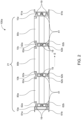
- Fig. 2 illustrates a cross section of the battery pack 100a according to Fig. 1 .
- the cross-sectional view of the battery pack 100a can also be considered as a side view of the battery pack 100a, wherein one or both of the longitudinal beams 13a, 13b is removed. Then, the side view of the battery pack 100a shows one of the opposing ends 17a, 17b of the crossbeams 10a, 10b, 10c, 10z.
- the longitudinal direction L of the crossbeams 10a, 10b, 10c, 10z is perpendicular to the drawing plane, i.e., the longitudinal direction L points into or out of the drawing plane.
- the elongation direction E of the longitudinal beams 13a, 13b is indicated by a dashed arrow.
- the crossbeams 10a, 10b, 10c, 10z and the rows of stacked battery cells 80a, 80b, 80c are stacked such that the inner crossbeams 10b, 10c and the rows of stacked battery cells 80a, 80b, 80c are alternately stacked between the two outer crossbeams 10a, 10z.
- the stacked arrangement of crossbeams 10a, 10b, 10c, 10z and rows of stacked battery cells 80a, 80b, 80c is referred to as a cell stack arrangement 21.
- the crossbeams 10a, 10b, 10c, 10z comprises a plurality of flanges 61a, 61b, 62a, 62b.
- the flanges 61a, 61b, 62a, 62b may be arranged on either edge of the crossbeams 10a, 10b, 10c, 10z along the longitudinal direction L of the crossbeams 10a, 10b, 10c, 10z.
- Two flanges 61a, 61b, 62a, 62b of one side of each of the crossbeams 10a, 10b, 10c, 10z may have a distance two each other which encompasses a lateral side of a row of stacked battery cells 80a, 80b, 80c.
- the outer flanges 61a, 61b of the outer crossbeams 10a, 10z are arranged and adapted, i.e., shaped, so provide a proper circumferential sealing flange for covers on top- and bottom side of the battery pack 100a.
- the outer crossbeams 10a, 10z can comprise integration members of connector- and cooling interfaces, e.g., an interface for a battery management system (not shown in the figures).
- Each of the crossbeams 10a, 10b, 10c, 10z comprises an integrated cooling channel 41 arranged within the crossbeam 10a, 10b, 10c, 10z.
- the cooling channel 41 of each of the crossbeams 10a, 10b, 10c, 10z extends into the longitudinal direction L of the crossbeam 10a, 10b, 10c, 10z so that the coolant fluid can flow from one of the opposing ends 17a of the crossbeam 10a, 10b, 10c, 10z through the crossbeam 10a, 10b, 10c, 10z to the other of the opposing ends 17b of the crossbeam 10a, 10b, 10c, 10z.
- Each of the crossbeams 10a, 10b, 10c, 10z comprises locking members 19.
- the looking members 19 of each of the crossbeams 10a, 10b, 10c, 10z are through holes which extend into the longitudinal direction L of the crossbeam 10a, 10b, 10c, 10d from one of the opposing ends 17a of the crossbeam 10a, 10b, 10c, 10z through the crossbeam 10a, 10b, 10c, 10z to the other of the opposing ends 17b of the crossbeam 10a, 10b, 10c, 10z.
- the crossbeams 10a, 10b, 10c, 10z are made out of Al-extrusion profiles to simply and cost-effectively integrate cooling channels 41 and the extruded through holes being the locking members 19 of the crossbeams 10a, 10b, 10c, 10z into the crossbeams 10a, 10b, 10c, 10z.
- the locking members 19 are arranged and adapted to receive the fasteners 16 so that the fasteners 16 extend into and engage with the locking members 19 of the crossbeams 10a, 10b, 10c, 10z.
- the fasteners 16 can comprise a threaded section to engage with the fasteners 16.
- Each of the crossbeams 10a, 10b, 10c, 10z comprises at each of the crossbeam ends 17a, 17b two locking members 19 adapted to receive one of the fasteners 16, each.
- the cooling channel 41 of each of the crossbeams 10a, 10b, 10c, 10z is arranged between the locking member 19 of the crossbeam 10a, 10b, 10c, 10z. This provides a symmetric distribution of load exerted by the fasteners 16.
- the cooling channel 41 is arranged between the two locking members 19. This provides a central arrangement of the cooling channel 41 and thereby an improved cooling of the rows of stacked battery cells 80a, 80b, 80c arranged adjacent to and in contact with the crossbeams 10a, 10b, 10c, 10z.
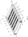
- Fig. 3 illustrates a perspective view of a battery frame 12 according to an embodiment.
- the battery frame 12 is analogously constructed as the battery frame 12 of the battery pack 100a as illustrated in Fig. 1 with the difference that the battery frame 12 according to Fig. 2 comprises a different number of crossbeams 10a, 10b, 10c, 10d, 10e, 10f, 10z and thus comprises a different number of retaining sections 15a, 15b, 15c, 15d, 15e, 15f and different longitudinal beams 13a, 13b, compared to the battery frame 12 of the battery pack 100a of Fig. 1 .
- a differently sized battery frame 12 is provided by compared to battery frame 12 the battery pack 100a as shown Fig. 1 .
- the battery frame 12 as shown in Fig. 3 can be used to assemble a battery pack 100b as shown and described with reference to Fig. 7 .
- Each of the longitudinal beams 13a, 13b comprises a duct retainer 42 in the form of a recess of the longitudinal beams 13a, 13b to retain one of the coolant distribution ducts 40.
- the duct retainer 42 is arranged between the openings 20 and extends along the elongation direction E of the longitudinal beams 13a, 13b.
- the coolant distribution ducts 40 are mechanically connected with the cooling channels 41 of the crossbeams 10a, 10b, 10c, 10z to allow coolant fluid to flow via the coolant distribution ducts 40 through the cooling channels 41 (see Fig. 2 for cooling channels 41).
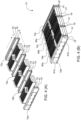
- Fig. 4 illustrates a method of assembling the battery pack 100a according to an embodiment.
- the battery pack 100a is shown in Figs. 1 and 2 and described with reference thereto.
- Fig.4 is subdivided into four subfigures, Fig. 4 (A), Fig. 4 (B) , Fig. 4 (C), and Fig. 4(D) to illustrate different steps of the method. Therein, performing a method step is indicated by one or more arrows with solid lines.
- the plurality of crossbeams 10a, 10b, 10c, 10z and the rows of stacked battery cells 80a, 80b, 80c are provided.
- the crossbeams 10a, 10b, 10c, 10z and the rows of stacked battery cells 80a, 80b, 80c are stacked such that the inner crossbeams 10b, 10c and the rows of stacked battery cells 80a, 80b, 80c are alternately stacked between the two outer crossbeams 10a, 10z as shown in Fig. 4 (B) .
- the length of the crossbeams 10a, 10b, 10c, 10z i.e., the elongation of the crossbeams 10a, 10b, 10c, 10z in the longitudinal direction L matches the elongation of the rows of stacked battery cells 80a, 80b, 80c in the longitudinal direction L.
- the stacked rows of stacked battery cells 80a, 80b, 80c and crossbeams 10a, 10b, 10c, 10z are referred to as cell stack arrangement 21.
- the cell stack arrangement 21 is compact and has an essentially rectangular cross-section, depending of the dimension of the battery pack 100a which is to be assembled.
- the longitudinal beams 13a, 13b, coolant distribution ducts 40 and fasteners 16 are provided.
- the battery frame can be closed by longitudinal beams 13a, 13b which will be joined with screw fasteners 16 from the lateral sides.
- the fasteners 16 comprise screws or bolts, and each of the locking members 19 comprises a hole to receive one of the screws or bolts.
- Each of the longitudinal beams 13a, 13b comprises a duct retainer 42 in the form of a recess of the longitudinal beams 13a, 13b to retain one of the coolant distribution ducts 40.
- the duct retainer 42 is arranged between the openings 20 and extends along the elongation direction E of the longitudinal beams 13a, 13b.
- the coolant distribution ducts 40 are mechanically connected with the cooling channels 41 of the crossbeams 10a, 10b, 10c, 10z to allow coolant fluid to flow via the coolant distribution ducts 40 through the cooling channels 41 (see Fig. 2 for cooling channels 41).
- the coolant distribution ducts 40 are arranged in the duct retainers 42 before the fasteners 16.
- the two longitudinal beams 13a, 13b and the crossbeams 10a, 10b, 10c 10z are mechanically interconnected with each other by the fasteners 16 extending into the longitudinal direction L of the crossbeams 10a, 10b, 10c, 10z through the openings 20 of the longitudinal beams 13a, 13b and into the locking members 19 of the crossbeams 10a, 10b, 10c, 10z.
- the resulting battery pack 100a is shown in Fig. 4 (D) .
- the battery pack 100a can be closed by a top cover and/or a bottom cover (not shown).
- Fig. 5 illustrates a method of assembling a battery pack 100a according to another embodiment.
- the battery pack 100a is shown in Figs. 1 and 2 and described with reference thereto.
- performing a method step is indicated by a arrow with a solid line.
- the method of assembling the battery pack 100a comprises first that a battery frame 12 as described in the present disclosure is provided. Further, the rows of stacked battery cells 80a, 80b, 80c are provided.
- One of the rows of stacked battery cells 80a, 80b, 80c is arranged in each of the retaining sections 15a, 15b, 15c provided by the battery frame 12.
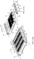
- Fig. 6 illustrates a method step of assembling a battery pack 100b according to another embodiment.
- the method step as shown in Fig. 6 is analogously performed as the method step as illustrated in Fig. 4 (A) with the difference that a different number of crossbeams 10a, 10b, 10c, 10d, 10e, 10f, 10z and a different number of rows of stacked battery cells 80a, 80b, 80c, 80d, 80e, 80f is provided.
- the inner crossbeam 10d is of the same type as one of the outer crossbeams 10a, 10z.
- first section of the cell stack arrangement 21 comprising the outer crossbeam 10a, the first role of stacked battery cells 80a, the inner crossbeam 10b, the second row of stacked battery cells 80b, the inner crossbeam 10c, and the third row of stacked battery cells 80c, then to assemble the second sections of the cell stack arrangement 21, comprising the fourth row of stacked battery cells 80d, the inner crossbeam 10e, the fifth row of stacked battery cells 80e, the inner crossbeam 10f, the sixth row of stacked battery cells 80f and the outer crossbeam 10z.
- the first and second sections of the cell stack arrangement 21 are assembled and joined together by the intermediate crossbeam 10d, which serves as an outer crossbeam for each of the sections of the cell stack arrangement 21.
- a further possibility to change the capacity, current or voltage of a battery pack 100a, 100b is, additionally or alternatively, to install longer or shorter rows of stacked battery cells 80a, 80b, 80c, 80d, 80e, 80f.
- the length of the crossbeams 10a, 10b, 10c, 10d, 10e, 10f, 10z is to be adapted.
- the assembly process of the battery pack 100a and the equipment needed for manufacture are the same.
- the crossbeams 10a, 10b, 10c, 10d, 10e, 10f, 10z and rows of stacked battery cells 80a, 80b, 80c, 80d, 80e, 80f can be analogously assembled to a battery pack 100b as shown in Fig. 4 (B) to Fig. 4 (D) with the difference that two different longitudinal beams 13a, 13b are provided. Specifically, if the width of the rows of stacked battery cells 80a, 80b, 80c, 80d, 80e, 80f in Figs. 4 and 6 equals, the two longitudinal beams 13a, 13b as to be mounted subsequent to the method step of Fig. 6 are longer than the two longitudinal beams 13a, 13b as mounted and shown in Figs.
- Fig. 7 illustrates a method of assembling a battery pack 100b according to another embodiment.
- the battery pack 100b is analogously constructed as the battery pack 100a as illustrated in Fig. 1 with the difference that the battery frame 12 is the battery frame as shown in Fig. 3 and described with reference thereto.
- the method of assembly is analogously performed as shown in Fig. 5 and explained with reference thereto, with the difference that the number of rows of stacked battery cells 80a, 80b, 80c, 80d, 80e, 80f is different in the embodiment of Fig. 7 compared to the number of rows of stacked battery cells 80a, 80b, 80c of the battery pack 100a of Fig. 1 .
Landscapes
- Chemical & Material Sciences (AREA)
- Chemical Kinetics & Catalysis (AREA)
- Electrochemistry (AREA)
- General Chemical & Material Sciences (AREA)
- Engineering & Computer Science (AREA)
- Manufacturing & Machinery (AREA)
- Aviation & Aerospace Engineering (AREA)
- Battery Mounting, Suspending (AREA)
Priority Applications (4)
| Application Number | Priority Date | Filing Date | Title |
|---|---|---|---|
| EP21203601.6A EP4170788A1 (de) | 2021-10-20 | 2021-10-20 | Batterierahmen, batteriepack, elektrofahrzeug, verfahren zur montage eines batterierahmens und verfahren zur montage eines batteriepacks |
| US17/969,595 US20230123420A1 (en) | 2021-10-20 | 2022-10-19 | Battery frame, battery pack, electric vehicle, method of assembling a battery frame, and method of assembling a battery pack |
| KR1020220135248A KR20230056613A (ko) | 2021-10-20 | 2022-10-19 | 전지 프레임, 전지 팩, 전기 차량, 전지 프레임 조립 방법 및 전지 팩 조립 방법 |
| CN202211285761.7A CN115995649A (zh) | 2021-10-20 | 2022-10-20 | 电池框架、电池包以及组装电池框架和电池包的方法 |
Applications Claiming Priority (1)
| Application Number | Priority Date | Filing Date | Title |
|---|---|---|---|
| EP21203601.6A EP4170788A1 (de) | 2021-10-20 | 2021-10-20 | Batterierahmen, batteriepack, elektrofahrzeug, verfahren zur montage eines batterierahmens und verfahren zur montage eines batteriepacks |
Publications (1)
| Publication Number | Publication Date |
|---|---|
| EP4170788A1 true EP4170788A1 (de) | 2023-04-26 |
Family
ID=78332577
Family Applications (1)
| Application Number | Title | Priority Date | Filing Date |
|---|---|---|---|
| EP21203601.6A Pending EP4170788A1 (de) | 2021-10-20 | 2021-10-20 | Batterierahmen, batteriepack, elektrofahrzeug, verfahren zur montage eines batterierahmens und verfahren zur montage eines batteriepacks |
Country Status (2)
| Country | Link |
|---|---|
| EP (1) | EP4170788A1 (de) |
| KR (1) | KR20230056613A (de) |
Citations (4)
| Publication number | Priority date | Publication date | Assignee | Title |
|---|---|---|---|---|
| US20090142650A1 (en) * | 2007-11-28 | 2009-06-04 | Wataru Okada | Battery system |
| EP3273500A1 (de) | 2016-07-21 | 2018-01-24 | Samsung SDI Co., Ltd. | Batteriesystem |
| US20200148066A1 (en) | 2018-11-13 | 2020-05-14 | Rivian Ip Holdings, Llc | Modular electric vehicle battery pack frame having extruded aluminum structural members |
| EP3664186A1 (de) * | 2017-12-20 | 2020-06-10 | Lg Chem, Ltd. | Batteriemodul sowie batteriepack und fahrzeug damit |
-
2021
- 2021-10-20 EP EP21203601.6A patent/EP4170788A1/de active Pending
-
2022
- 2022-10-19 KR KR1020220135248A patent/KR20230056613A/ko unknown
Patent Citations (4)
| Publication number | Priority date | Publication date | Assignee | Title |
|---|---|---|---|---|
| US20090142650A1 (en) * | 2007-11-28 | 2009-06-04 | Wataru Okada | Battery system |
| EP3273500A1 (de) | 2016-07-21 | 2018-01-24 | Samsung SDI Co., Ltd. | Batteriesystem |
| EP3664186A1 (de) * | 2017-12-20 | 2020-06-10 | Lg Chem, Ltd. | Batteriemodul sowie batteriepack und fahrzeug damit |
| US20200148066A1 (en) | 2018-11-13 | 2020-05-14 | Rivian Ip Holdings, Llc | Modular electric vehicle battery pack frame having extruded aluminum structural members |
Also Published As
| Publication number | Publication date |
|---|---|
| KR20230056613A (ko) | 2023-04-27 |
Similar Documents
| Publication | Publication Date | Title |
|---|---|---|
| US11949084B2 (en) | Battery pack comprising frame profile having integral refrigerant circuit member | |
| EP3482429B1 (de) | Batteriesystem und fahrzeug | |
| US11139521B2 (en) | Battery submodule carrier, battery submodule, battery system and vehicle | |
| EP3267508B1 (de) | Batteriesystem mit batteriemodulträger und fahrzeug mit einem batteriesystem | |
| US10622601B2 (en) | Battery module carrier, battery system and use of a modified H-beam as battery module carrier | |
| US11721856B2 (en) | Battery pack for a vehicle | |
| CN113497302A (zh) | 电池模块、用于组装电池模块的方法和包括电池包的车辆 | |
| EP3772122B1 (de) | Batteriemodul mit einer multifunktionalen endplatte | |
| EP4170788A1 (de) | Batterierahmen, batteriepack, elektrofahrzeug, verfahren zur montage eines batterierahmens und verfahren zur montage eines batteriepacks | |
| US20230123420A1 (en) | Battery frame, battery pack, electric vehicle, method of assembling a battery frame, and method of assembling a battery pack | |
| EP4180262A1 (de) | Austauschbarer batteriezellenträger mit geteiltem profil | |
| CN111670508B (zh) | 用于车辆电池组的固定元件和包括其的车辆电池组 | |
| EP3637537B1 (de) | Umgehungsrohr für einen kühlkreislauf eines fahrzeugbatteriepacks | |
| CN219226503U (zh) | 电池组、用于其的框架和包括其的车辆 | |
| EP4037083A1 (de) | Schutzanordnung und batteriegehäuse damit | |
| US20220255192A1 (en) | Assembly set for assembling a carrier framework for a stack of battery cell blocks | |
| US20230121830A1 (en) | Battery module, a battery pack, an electric vehicle, a cell carrier, a cell assembly | |
| EP3637536A1 (de) | Kupplungselement für ein batteriepaket eines fahrzeugs | |
| US20210305643A1 (en) | Robust interface for cooler to housing | |
| CN114843687A (zh) | 保护组件以及包括该保护组件的电池壳体 |
Legal Events
| Date | Code | Title | Description |
|---|---|---|---|
| PUAI | Public reference made under article 153(3) epc to a published international application that has entered the european phase |
Free format text: ORIGINAL CODE: 0009012 |
|
| STAA | Information on the status of an ep patent application or granted ep patent |
Free format text: STATUS: REQUEST FOR EXAMINATION WAS MADE |
|
| 17P | Request for examination filed |
Effective date: 20221209 |
|
| AK | Designated contracting states |
Kind code of ref document: A1 Designated state(s): AL AT BE BG CH CY CZ DE DK EE ES FI FR GB GR HR HU IE IS IT LI LT LU LV MC MK MT NL NO PL PT RO RS SE SI SK SM TR |
|
| STAA | Information on the status of an ep patent application or granted ep patent |
Free format text: STATUS: EXAMINATION IS IN PROGRESS |
|
| 17Q | First examination report despatched |
Effective date: 20240422 |