EP4170627B1 - Hilfsverfahren und vorrichtung zur steuerung eines luftfahrzeugs im flug - Google Patents
Hilfsverfahren und vorrichtung zur steuerung eines luftfahrzeugs im flug Download PDFInfo
- Publication number
- EP4170627B1 EP4170627B1 EP22185811.1A EP22185811A EP4170627B1 EP 4170627 B1 EP4170627 B1 EP 4170627B1 EP 22185811 A EP22185811 A EP 22185811A EP 4170627 B1 EP4170627 B1 EP 4170627B1
- Authority
- EP
- European Patent Office
- Prior art keywords
- aircraft
- height
- symbol
- display device
- circle
- Prior art date
- Legal status (The legal status is an assumption and is not a legal conclusion. Google has not performed a legal analysis and makes no representation as to the accuracy of the status listed.)
- Active
Links
Images



Classifications
-
- G—PHYSICS
- G08—SIGNALLING
- G08G—TRAFFIC CONTROL SYSTEMS
- G08G5/00—Traffic control systems for aircraft
- G08G5/20—Arrangements for acquiring, generating, sharing or displaying traffic information
- G08G5/21—Arrangements for acquiring, generating, sharing or displaying traffic information located onboard the aircraft
-
- G—PHYSICS
- G08—SIGNALLING
- G08G—TRAFFIC CONTROL SYSTEMS
- G08G5/00—Traffic control systems for aircraft
- G08G5/50—Navigation or guidance aids
- G08G5/54—Navigation or guidance aids for approach or landing
-
- G—PHYSICS
- G08—SIGNALLING
- G08G—TRAFFIC CONTROL SYSTEMS
- G08G5/00—Traffic control systems for aircraft
- G08G5/70—Arrangements for monitoring traffic-related situations or conditions
- G08G5/74—Arrangements for monitoring traffic-related situations or conditions for monitoring terrain
Definitions
- the present invention relates to the field of piloting aids for aircraft and rotorcraft in particular.
- the present invention relates to a method for assisting in piloting an aircraft in flight and to a system for assisting in piloting an aircraft in flight.
- the aircraft may be a rotorcraft comprising at least one rotating wing, for example at least one lift rotor, enabling it in particular to perform stationary flights as well as low-speed forward flights.
- An aircraft may also perform takeoffs and landings on landing areas of reduced dimensions.
- An aircraft can land on prepared landing pads.
- a prepared landing pad can be located on the ground, on the roof of a building, as well as on a boat or a platform located at sea.
- An aircraft may also land on unprepared landing areas located in an urban environment, and in fact potentially surrounded by buildings and/or street furniture in particular.
- An aircraft may also land on unprepared landing areas located in a natural environment and in this case potentially surrounded by vegetation and likely not to be perfectly flat, or even to contain rocks.
- the cockpit of an aircraft may include a transparent area, for example glazed, at the level of the pilot's feet so as to allow him to see the ground.
- a transparent area for example glazed
- the vision of the ground remains partial and the observable area has dimensions that reduce as the aircraft approaches the ground.
- the pilot may not be able to see possible contact points for at least some of the aircraft's landing gear.
- An aircraft may also include a landing point indication system as described in the document EP 2708853 .
- This system comprises at least one camera and a screen displaying a view of the area located under the aircraft.
- This system also comprises a device for measuring an attitude of the aircraft.
- the screen displays an indication of the projected position on the ground of the aircraft, in particular as a function of its attitude.
- the document US 2012/0154178 describes a method for presenting aircraft attitude and heading information on a display, consisting of using data provided by an inertial unit to represent three-dimensional graphic elements on a two-dimensional display, and presenting the attitude (roll, pitch, or even yaw) and heading information on the two-dimensional display by associating them with at least one spatial attitude graphic element indicating the attitude of the aircraft.
- a fixed transparent sphere represents an inertial reference frame, with two upper and lower half-spheres representing the sky and the ground respectively.
- the present invention aims to overcome the limitations mentioned by proposing assistance in piloting an aircraft by allowing the pilot to visualize, substantially in real time or quasi-real time, the area located under the aircraft as well as the position of the aircraft.
- the present invention then relates to a method for assisting in piloting an aircraft in flight according to claim 1, as well as a system for assisting in piloting an aircraft in flight according to claim 15.
- the structure of the aircraft includes, for example, a cell, or even a tail boom and/or wings.
- a pilot and possibly other occupants are installed in the cell during the flight of the aircraft.
- the horizon circle represents the projection of the horizon line around the aircraft.
- the diameter of the horizon circle is constant, i.e. independent of the height and attitude of the aircraft.
- the value of the diameter of the horizon circle is predetermined, in particular as a function of the dimensions of the display device as well as the dimensions of the representation and/or the optical characteristics of the capture device.
- the first position and the second position which correspond respectively to vertical projections on the area flown over of a first reference point of the aircraft and of a second reference point of the image capture device move on the representation during changes in attitude of the aircraft.
- the second position can advantageously be calculated without using the height of the aircraft, although this position is a function of this height.
- This second position is the position of a vertical projection onto the area flown over of a second reference point of the image capture device.
- This second position can then be determined relative to the center of the image captured by the image capture device as a function of a parameter of the image capture device and the attitude of the aircraft.
- This parameter is for example the focal length of the lens of the image capture device, this focal length being fixed in this case.
- This parameter can also be an equivalent focal length when the representation of the area flown over is formed from several images.
- this second position can be calculated based on the attitude and height of the aircraft.
- the horizon circle which is always centered on the second position also moves on the representation during changes in attitude of the aircraft.
- the horizon circle may be displayed only partially on the representation, for example when the aircraft has a large pitch-up angle and/or roll angle.
- the horizon circle thus allows the pilot of the aircraft to visualize on the representation changes in attitude of the aircraft as well as obstacles located high up, in particular above the horizon circle.
- the pilot can locate the aircraft in relation to the area flown over, and in particular in relation to the landing area and any obstacles or objects located on or near the landing area.
- the pilot can then safely land on any type of landing area, prepared or not.
- the image capture device is directed toward the ground and is used to capture images of the area overflown by the aircraft when the aircraft is in flight.
- the image capture device may be attached to the airframe or tail boom, or even to a wing.
- the area flown over can be, for example, the ground, the roof of a building, a boat or even a platform located at sea.
- the height of the aircraft relative to the overflown area is equal to the shortest distance between the aircraft and the overflown area, this height being defined parallel to the direction of Earth's gravity.
- the height of the aircraft may be defined for example relative to a predetermined point on the aircraft.
- the attitude of the aircraft characterizes the attitude of the aircraft, namely its roll angle and its pitch angle around respectively a roll axis and a pitch axis of the aircraft.
- the aircraft has a zero attitude when its roll angle and its pitch angle are simultaneously equal to zero.
- the roll and pitch axes of the aircraft are then parallel to a horizontal plane defined perpendicular to the direction of Earth's gravity.
- the method according to the invention may further comprise one or more of the following characteristics, taken alone or in combination.
- the representation of the area flown over covers an angular field of 360° in a horizontal plane and at least 180° in a vertical plane when the attitude of the aircraft is zero, the vertical plane being parallel to a direction of Earth's gravity and the horizontal plane being perpendicular to the direction of Earth's gravity.
- the pilot has an overall view of the area flown over in order to understand all the obstacles likely to be in the area flown over, in particular obstacles above the horizon circle.
- the representation of the area flown over covers an angular field of 360° in a horizontal plane and at least 220° in a vertical plane when the aircraft attitude is zero.
- This representation of the area flown over is sufficient to allow the pilot of the aircraft to become aware of the environment of the landing area and then to carry out a landing manoeuvre in complete safety. Furthermore, in this case, the representation of the area flown over allows the pilot to have an idea of the attitude of the aircraft, in particular thanks to the relative movements of the sky on the representation of the area flown over and the position of the horizon circle which may be off-centre on the representation of the area flown over.
- the image capture device can comprise at least one single camera or one single photographic device.
- the image capture device may comprise a single camera or a single photographic apparatus fixed relative to the structure of the aircraft and provided with a lens covering an angular field of 360° in a plane perpendicular to an optical axis of the camera or photographic apparatus and a field of at least 180° in a plane parallel to this optical axis.
- This optical axis is for example parallel to a direction of Earth's gravity when the aircraft has a zero attitude.
- the second reference point of the image capture device is then the center of this lens. The representation of the area flown over then corresponds exactly to the image captured by the image capture device.
- the camera or photographic apparatus may include a "fish-eye" type lens.
- a "fish-eye” type lens causes by its construction a deformation of the captured image according to an equidistant or equisolid projection for example.
- the image capture device may comprise a single camera or a single photographic device movable relative to the structure of the aircraft in order to cover an angular field of 360° in a horizontal plane and a field of at least 180° in a vertical plane.
- the image capture device may comprise several cameras or several photographic devices fixed relative to the structure of the aircraft and jointly covering an angular field of 360° in a horizontal plane and a field of at least 180° in a vertical plane.
- the representation of the area flown over is then constructed by the calculator from the images provided by the image capture device.
- the representation of the area flown over can have an equidistant or equisolid projection for example.
- the symbol can be represented on the display device with dimensions variable according to the height.
- the dimensions of the symbol can be representative of the dimensions of the vertical projection of the aircraft on the area flown over, being variable according to the height of the aircraft.
- the method may in this case include an additional step of calculation by the calculator of the dimensions of the symbol at least as a function of the height of the aircraft.
- This additional calculation step optionally uses the dimensions of the aircraft and the height of the aircraft to calculate the dimensions of the symbol.
- the symbol may also be represented on the display device with constant dimensions when the height is greater than a first predetermined threshold and the symbol may be represented on the display device with variable dimensions, possibly representative of the dimensions of the vertical projection of the aircraft on the area flown over, at least as a function of the height when the height is less than or equal to the first threshold.
- the dimensions of the symbol enable the pilot to assess the height of the aircraft.
- the first threshold is for example equal to 150 feet (150fts), one foot being equal to 0.3048 meters.
- the method may also include the additional step of calculating the dimensions of the symbol, this step being applied when the dimensions of the symbol are variable depending on the height.
- a hysteresis threshold can be used.
- the first threshold then comprises a first high threshold and a first low threshold.
- the symbol is represented with constant dimensions when the height is greater than the first high threshold and the symbol is represented with variable dimensions when the height is less than or equal to the first low threshold.
- the symbol is represented with constant dimensions.
- the symbol is represented with variable dimensions.
- a first threshold hysteresis value is equal to the difference between the first high threshold and the first low threshold, and is for example equal to 20 feet.
- the symbol can be represented on the display device with different shapes when said height is greater than a first predetermined threshold and when said height is less than or equal to said first threshold.
- a first threshold can also be a hysteresis threshold as previously mentioned.
- the method can also simultaneously associate a change in the shape of the symbol and a variation in the dimensions of the symbol with the passage of the first threshold.
- a first symbol can thus be represented on the display device with constant dimensions when the height is greater than the first predetermined threshold and a second symbol, different from the first symbol, can be represented on the display device with variable dimensions depending on the height of the aircraft when the height is less than or equal to the first threshold.
- the symbol can be displayed on the display device with constant dimensions regardless of the height of the aircraft. In this way, regardless of the height of the aircraft, the aircraft symbol is displayed with the same dimensions.
- the aircraft may comprise at least one lifting rotor, arranged for example above the structure, and the symbol then comprises: a shape representing the structure and at least one rotor circle corresponding to the lift rotor.
- the method then comprises the additional step of calculating the dimensions of the symbol and during this additional calculation step, the dimensional characteristics of said at least one rotor circle and the dimensional characteristics of the shape representing the structure are calculated as a function respectively of the diameter of said at least one lift rotor and the dimensions of the structure as well as the height of the aircraft.
- This additional calculation step makes it possible in particular to transfer said at least one rotor circle and the shape representing the structure from a reference frame linked to the aircraft to a reference frame linked to the image capture device
- the aircraft comprising at least one lift rotor
- the first reference point of the aircraft can be a center of rotation of a lift rotor among said at least one lift rotor.
- the first measuring device may comprise for example at least one inertial unit or a device known by the acronym AHRS for the English designation "Attitude and Heading Reference System", at least one inclinometer or others, in order to determine or measure the attitude of the aircraft, namely its roll and pitch angles.
- the second measuring device can make it possible to directly measure the height of the aircraft relative to the area flown over and can include for this purpose a radiosonde for example.
- the step of determining a height of the aircraft relative to the area flown over thus includes a measurement of this height by the second measuring device.
- the second measuring device may alternatively comprise a barometric altimeter for measuring a current atmospheric pressure, which is then compared with an atmospheric pressure at the altitude of the area flown over in order to calculate the height of the aircraft relative to the area flown over.
- the second measuring device may alternatively comprise at least one receiver of a satellite positioning system.
- the receiver provides a position of the aircraft in a terrestrial reference frame, for example in the form of coordinates in latitude, longitude and altitude relative to a reference level, generally sea level. This position of the aircraft in the terrestrial reference frame is then combined with a stored three-dimensional terrain model or with information from a stored terrain database in order to determine the height of the aircraft relative to the area flown over.
- Three-dimensional terrain modeling can be derived from a terrain database stored in memory.
- the step of determining a height of the aircraft relative to the area flown over can alternatively use the focal length of a lens of the image capture device, thanks to adapted processing of the focal length value.
- the method may comprise a step of displaying on the display device a safety circle around the symbol.
- This safety circle represents a safety bubble around the aircraft which must be respected, for example during a landing, no obstacle must interfere with the safety bubble and therefore interfere with the safety circle on the representation of the area flown over.
- the safety circle may be centered on an intersection of the diagonals of a rectangle in which the symbol is inscribed.
- the safety circle can have a variable diameter depending on the height. In this way, the diameter of the safety circle displayed on the representation can be representative of the actual diameter of the safety bubble to be respected around the aircraft.
- the step of displaying the safety circle may in this case include a sub-step of calculation by the computer to calculate the diameter of the safety circle as a function of the height of the aircraft and a diameter of a lift rotor of the aircraft.
- the diameter of the safety bubble is for example equal to twice the diameter of the aircraft's lift rotor.
- the symbol includes a shape representing the structure of the aircraft and at least one rotor circle and the dimensions of the symbol are also variable depending on the height of the aircraft, the diameter of the safety circle is then equal to twice the diameter of the rotor circle.
- the safety circle may be displayed on the display device only when the height is less than or equal to the second threshold. In this way, when the safety circle is displayed, the pilot knows that the aircraft is approaching the overflown area and visualizes the information of the dimensions of the vertical projection of the safety bubble on the overflown area.
- the second threshold is for example equal to 300 feet (300fts).
- the method may comprise a step of displaying on the viewing device markers of the cardinal points, namely the directions of North, South, East and West. These markers are for example displayed near the horizon circle.
- the method may comprise a step of displaying on the display device a heading indicator of the aircraft.
- the heading of the aircraft is aligned with the direction of the roll axis of the aircraft and represented on the representation of the area flown over in front of the aircraft.
- the heading indicator of the aircraft is for example displayed near the horizon circle.
- the method may comprise a step of displaying on the display device an indicator of wind experienced by the aircraft.
- This wind indicator carries information on speed and/or wind direction, for example provided by an anemometer or a wind vane of the aircraft.
- the present invention also relates to a system for assisting in piloting an aircraft in flight.
- the aircraft comprises a structure provided for example with a cell and possibly a tail boom and/or wings, and at least one lift rotor arranged for example above the cell.
- This system is thus configured for the implementation of the method for assisting in piloting an aircraft in flight described above.
- This system can be installed on an aircraft at the time of manufacture or be added to an aircraft already in service in order to improve its safety and allow the pilot to easily and completely visualize a landing area and its surroundings.
- the image capture device may comprise at least one camera or at least one photographic apparatus.
- the image capture device may comprise a single camera or at least one photographic apparatus provided with a lens covering an angular field of 360° in a plane perpendicular to an optical axis of the camera or photographic apparatus and at least 180° in a vertical plane parallel to this optical axis.
- the second reference point of the image capture device is the center of the lens.
- FIG. 1 represents a rotary wing aircraft 1 equipped with a system 10 for assisting in piloting the aircraft 1 in flight.
- the aircraft 1 comprises, for example, a structure 2.
- the structure 2 may be equipped with a cell 4 and a tail boom 5 as well as at least one lift rotor 3 arranged, for example, above the cell 4.
- Other configurations of aircraft 1 are conceivable within the framework of the present invention, the structure 2 being able, for example, to comprise wings.
- the system 10 comprises an image capture device 11 carried by the structure 2 and directed towards the ground, a first measuring device 16 for determining an attitude of the aircraft 1, a second measuring device 17 for determining a height of the aircraft 1 relative to the area flown over, a display device 15 and a calculator 13.
- the image capture device 11 is positioned vertically to a center of rotation 35 of the lift rotor 3 when the aircraft 1 has a zero attitude, a vertical direction being parallel to the direction of Earth's gravity. But the capture device 11 can alternatively be positioned at another position under, or even in the cell 4, or under or in the tail boom 5, or even under or in wings of the structure 2.
- the viewing device 15 is positioned in the cell 4 in a location visible to a pilot of the aircraft 1.
- the display device 15 may comprise a screen.
- the display device 15 may alternatively comprise a portion of the windshield of the aircraft 1 or a digital tablet on board the aircraft 1, or any other display means.
- the aircraft 1 may also include an anemometer 18 or a wind vane in order to determine a direction and/or a speed of the wind experienced by the aircraft 1.
- the computer 13 may comprise one or more processing units each having for example at least one processor and at least one memory 12, at least one integrated circuit, at least one programmable system, at least one logic circuit, these examples not limiting the scope given to the expression computer.
- the term processor may designate both a central processing unit known by the acronym CPU, a graphics processing unit GPU, a digital unit known by the acronym DSP, a microcontroller, etc.
- the computer 13 communicates, by a wired connection or a wireless connection, with the first and second measuring devices 16, 17, the image capture device 11, the memory 12 and the display device 15 as well as possibly with the anemometer 18 or the wind vane.
- the system 10 for assisting with piloting the aircraft 1 in flight may also include a memory 19, communicating with the computer 13.
- the system 10 for assisting in piloting the aircraft 1 in flight is configured to implement a method for assisting in piloting the aircraft 1 in flight, a block diagram of which is shown in the figure 2 .
- a memory 12, 19 may include a code or a code segment applied by the computer 13 for carrying out this method. This method includes the following steps.
- a determination step 110 for determining an attitude of the aircraft 1 is carried out using the first measuring device 16.
- the first measuring device 16 may comprise at least one inertial unit or an AHRS device.
- the first measuring device 16 then transmits a signal, for example analog or digital, electrical or optical, to the calculator 13, this signal carrying information relating to the attitude of the aircraft 1.
- the attitude of aircraft 1 is defined by a roll angle and a pitch angle of aircraft 1 around respectively a roll axis and a pitch axis of aircraft 1.
- the method comprises a determination step 120 for determining a height of the aircraft 1 relative to the overflown area is carried out using the second measuring device 17, this height being equal to the distance between the aircraft 1 and the overflown area defined parallel to the direction of Earth's gravity.
- the second measuring device 17 then transmits a signal, for example analog or digital, electrical or optical, to the computer 13, this signal carrying information relating to the height of the aircraft 1.
- the second measuring device 17 may for example comprise a radiosonde directly measuring this height of the aircraft 1 relative to the area flown over, in a vertical direction, parallel to the direction of Earth's gravity.
- the second measuring device 17 may comprise a barometric altimeter for measuring a current atmospheric pressure.
- the determination step 120 may then comprise a sub-step 123 of measuring a current atmospheric pressure around the aircraft 1 carried out using the barometric altimeter.
- a calculation sub-step 124 is carried out by the computer 13 or a processing unit of the second measuring device 17 in order to determine the height of the aircraft 1 by comparing the current atmospheric pressure with an atmospheric pressure at the altitude of the area flown over, this atmospheric pressure at the altitude of the area flown over having been previously stored in a memory of the aircraft 1, by example following a setting using an aircraft interface 1.
- the second measuring device 17 may comprise a receiver of a satellite location system.
- the determination step 120 may then comprise a determination sub-step 125 for determining a position of the aircraft 1 in a terrestrial reference frame carried out using the receiver of the satellite location system.
- a calculation sub-step 126 for calculating the height of the aircraft 1 relative to the area flown over is carried out by the computer 13 or another processing unit using the position of the aircraft 1 in the terrestrial reference frame and a three-dimensional terrain model or a stored terrain database.
- the three-dimensional terrain modeling or terrain database may be stored in the memory 12, 19 or in a complementary memory integrated for example in the system 10 or in the second measuring device 17.
- the determination step 120 can use the focal length of a lens of the camera or of the photographic apparatus of the image capture device 11 to determine the height of the aircraft 1 relative to the area flown over, using for example an adapted processing of this focal length.
- the method comprises a capture step 130 for capturing at least one image of the area flown over and also using the image capture device 11.
- the image capture device 11 then transmits a signal, for example analog or digital, electrical or optical, to the computer 13, this signal carrying information relating to at least one captured image of the area flown over.
- the image capture device 11 may comprise a single camera or a single photographic device fixed relative to the structure 2, as shown in the figure. figure 1 .
- the image capture device 11 covers an angular field of 360° in a horizontal plane and an angular field of at least 180° in a vertical plane.
- the image capture device 11 may alternatively comprise a single camera or a single photographic device that is mobile relative to the structure 2.
- the camera or photographic device then moves in a rotational movement relative to a support secured to the structure 2, for example in order to cover an angular field of 360° in a horizontal plane and an angular field of at least 180° in a vertical plane.
- the image capture device 11 may alternatively comprise several cameras or several photographic devices fixed relative to the structure 2 and jointly covering for example an angular field of 360° in a horizontal plane and an angular field of at least 180° in a vertical plane.
- the determining steps 110, 120 and 130 can be carried out sequentially as shown or in parallel, namely substantially simultaneously.
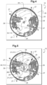
- the method comprises a display step 140 for displaying on the viewing device 15 a representation 20, as illustrated in Figures 4 to 6 of the area flown over.
- the computer 13 then transmits a signal, for example analog or digital, electrical or optical, to the display device 15 to display the representation 20, this signal carrying information relating to the representation 20.
- the representation 20 of the area flown over covers for example an angular field of 360° in a horizontal plane and at least 180° in a vertical plane when the attitude of the aircraft 1 is zero, the vertical plane being parallel to a direction of the Earth's gravity and the horizontal plane being perpendicular to the direction of the Earth's gravity.
- the representation 20 covers an angular field of 360° in a horizontal plane and of at least 220° in a vertical plane when the attitude of the aircraft 1 is zero.
- the representation 20 is formed by each image captured successively by the image capture device 11 when it comprises a single camera or a single photographic device fixed relative to the structure 2.
- the computer 13 constructs the representation 20 from the images captured by the camera(s) or the photographic apparatus(es) and transmitted to the computer 13, so as to form a single image of the area flown over covering the required angular field.
- the display step 140 then comprises a complementary step 145 of constructing the representation 20 from the images captured by the camera(s) or the photographic apparatus(es), this complementary step 145 of constructing the representation 20 from the images captured by the camera(s) or the photographic apparatus(es), this complementary step 145 of constructing being carried out for example by the computer 13 or another processing unit.
- This representation 20 allows a pilot of the aircraft 1 to have a complete view of the area flown over located below the aircraft 1.
- the method comprises a calculation step 150 for calculating a first position 33 on the representation 20 of a vertical projection on the overflown area of a first reference point 31 of the aircraft 1 produced using the calculator 13, as a function of the attitude of the aircraft 1 and the height of the aircraft 1 relative to the overflown area.
- the vertical projection of the first reference point 31 on the overflown area is carried out parallel to the direction of Earth's gravity.
- the calculator 13 determines the first position 33 on the representation 20 using a stored law, a table of values or others.
- the calculator 13 stores this first position 33 in a memory 12, 19.
- the computer 13 can thus determine and store the first successive positions 33 during a flight of the aircraft 1.
- the method comprises a calculation step 160 for calculating a second position 113 on the representation 20 of a vertical projection on the area flown over of a second reference point 111 of the image capture device 11 produced using the calculator 13, as a function of the attitude of the aircraft 1.
- the vertical projection of the second reference point 111 on the area flown over is carried out parallel to the direction of Earth's gravity.
- the calculator 13 determines, using a stored law, a table of values or others, the second position 113 on the representation 20, and optionally stores this second position 113 in a memory 12, 19.
- the calculator 13 can thus determine and store the successive second positions 113 during a flight of the aircraft 1.
- the stored law or the table of values may for example involve a parameter of the image capture device 11 such as the focal length of the lens of the image capture device.
- the distance between the second position and the center of an image captured by the image capture device 11 is for example equal to the product of a coefficient depending on this parameter of the image capture device multiplied by the attitude angle of the aircraft in the case of an equidistant projection. This distance is for example equal to the product of a coefficient depending on this parameter of the image capture device multiplied by the sine of the attitude angle of the aircraft in the case of an equisolid projection.
- the first reference point 31 and the second reference point 111 are specific points respectively of the aircraft 1 and of the image capture device 11.
- the reference point 31 is for example a center of rotation 35 of the lift rotor 3 of the aircraft 1 and the second reference point 111 is for example the center of the lens of the camera or of the photographic apparatus of the image capture device 11 as shown in the figure. figure 3 ,.
- FIG. 3 represents the first and second positions 33,113 defined by vertical projection of the first and second reference points 31,111 on the representation 20.
- a display step 170 for displaying on the display device 15 a symbol 21 representing the aircraft 1 is carried out, a point of origin of the symbol 21 being positioned on the first position 31.
- the computer 13 transmits a signal, for example analog or digital, electrical or optical, to the display device 15 to display the symbol 21, this signal carrying information relating to the symbol 21 and to the first position 33.
- Figures 4 to 6 represent the display of symbol 21 positioned on the first position 33 on the device visualization 15 superimposed on the representation 20 of the area flown over.
- the pilot of the aircraft 1 can view the symbol 21 on the representation 20 and, consequently, on the area flown over in order in particular to anticipate and prepare a landing by having a vision of the aircraft in relation to the area flown over, to a potential landing zone and to possible obstacles.
- the symbol 21 can be represented on the display device 15 with constant dimensions regardless of the height of the aircraft 1.
- the symbol 21 can alternatively be represented on the display device 15 with variable dimensions depending on this height of the aircraft 1.
- the method then comprises an additional calculation step 165 to calculate, using the calculator 13 and a stored law, a table of values or others, the dimensions of the symbol 21 depending on the height of the aircraft 1.
- the dimensions of the symbol 21 can for example correspond, on the representation 20 to the dimensions of the vertical projection of the aircraft 1 on the area flown over.
- the calculator 13 then transmits to the display device 15 a signal, for example analog or digital, electrical or optical, carrying information relating to the dimensions of the symbol 21.
- the additional calculation step 165 takes into account the scale used for displaying the area flown over on the representation 20.
- This scale may for example be a function of a focal length of the camera(s) or photographic apparatus of the image capture device 11 and possibly of a coefficient applied by the calculator 13 for displaying the representation 20 on the viewing device 15.
- the symbol 21 can take various forms, such as a cross, a circle.
- the point of origin of the symbol 21 can for example be the center of the symbol 21.
- the symbol 21 can alternatively take the form of an aircraft seen from above and include in particular a rotor circle 213 representing the lift rotor 3 and a shape 212 representing the structure 2 as shown in the figures 5 And 6 .
- the origin point of symbol 21 can in this case be the center of rotor circle 213.
- the computer 13 determines the dimensions of the symbol 21, for example the dimensional characteristics of the rotor circle 213 and of the shape 212 using a stored law, a table of values or others as a function respectively of a diameter of the lift rotor 3 and the dimensions of the structure 2 as well as the height of the aircraft 1.
- the computer 13 transmits to the display device 15 a signal, for example analog or digital, electrical or optical, carrying information relating to the dimensions of the symbol 21.
- the symbol 21 can alternatively be represented on the display device 15 with constant dimensions when the height of the aircraft 1 is greater than this first threshold and the symbol 21 can be represented on the display device 15 with variable dimensions depending on this height, as previously mentioned, when the height is less than or equal to the first threshold.
- the computer 13 compares the height to the first threshold. Therefore, if the height is greater than this first threshold, the computer 13 transmits to the display device 15 a signal carrying information relating to constant dimensions of the symbol 21 and to the first position 31 and if when the height is less than or equal at the first threshold, the calculator 13 calculates the dimensions of the symbol 21 in particular as a function of this height and transmits to the display device 15 a signal carrying information relating to these dimensions of the symbol 21 and to the first position 31.
- the additional calculation step 165 is therefore carried out as a function of the height of the aircraft 1 and the first threshold, namely when the height is less than or equal to the first threshold. Consequently, the symbol 21 representing the dimensions of the vertical projection of the aircraft 1 on the area flown over when the aircraft 1 is displayed when the aircraft 1 is located near the area flown over, namely at a height less than or equal to the first threshold, in order to assist the pilot during these maneuvers.
- the first threshold may be a hysteresis threshold and as such comprise a first low threshold and a first high threshold.
- the symbol 21 is then represented with constant dimensions when the height is greater than the first high threshold and the symbol 21 is represented with variable dimensions when the height is less than or equal to the first low threshold.
- the manner of displaying the symbol namely with constant or variable dimensions, is not modified.
- the method comprises a display step 180 for displaying on the display device 15 a horizon circle 25 representing a horizon line.
- the horizon circle 25 represents the projection of the horizon line around the aircraft 1.
- the horizon circle 25 is displayed with a constant diameter value, independently of the height and attitude of the aircraft 1.
- the horizon circle 25 is always centered on the second position 113.
- the second position 113 can therefore move on the representation 20 when the attitude of the aircraft 1 varies and the ... horizon circle 25 may then not appear entirely on the representation 20, in particular when the roll angle and/or the pitch angle of the aircraft 1 is large.
- the computer 13 transmits for this purpose to the display device 15 a signal, for example analog or digital, electrical or optical, carrying information relating to the dimensions of the horizon circle 25 and to the second position 113.
- the image capture device 11 comprises a single camera positioned vertically above the center of rotation 35 of the lift rotor 3 when the aircraft 1 has a zero attitude, its roll and pitch angles being equal to zero.
- An optical axis 117 of the image capture device 11 is vertical when the aircraft 1 has a zero attitude.
- the first reference point 31 and the second reference point 111 are in fact located on this optical axis 117. Consequently, the first position 33 and the second position 113 are displayed together and positioned at the center of the representation 20 when the aircraft 1 has a zero attitude as shown in the figures 3 And 4 .
- the horizon circle 25 and the symbol 21 are at the first position 33 and the second position 113 and therefore positioned at the center of the representation 20.
- the first position 33 and the second position 113 are distinct and the horizon circle 25 is eccentric relative to the representation 20.
- Such a configuration may be the consequence of the use of an image capture device 11 comprising for example a single camera offset longitudinally from the vertical of the center of rotation 35 of the lift rotor 3.
- Such a camera may for example be positioned under the tail boom 5 according to the aircraft example 1 shown in the figure 3 .
- the pilot of the aircraft 1 can view on the representation 20 the projection of the horizon line around the aircraft 1 in order to facilitate his vision of the area flown over and of the potential landing area as well as of the obstacles, in particular the obstacles in height situated above the horizon circle 25.
- the pilot of the aircraft 1 can also, by means of the position of the horizon circle 25 and of his possible movements on the representation 20, have a vision of the changes in attitude of the aircraft 1.
- the horizon circle 25 is for example displayed on a viewing device 15 having dimensions of 150mm x 150mm with a diameter equal to 123mm.
- the method may comprise a display step 190 for displaying on the display device 15 a safety circle 26 around the symbol 21.
- the safety circle 26 is for example centered on an intersection 263 of the diagonals of a rectangle 265 in which the symbol 21 is inscribed.
- the computer 13 then transmits to the display device 15 a signal carrying information, for example analog or digital, electrical or optical, relating to the dimensions of the safety circle 26 and its position around the symbol 21.
- This safety circle 26 allows the pilot to visualize a safety bubble around the aircraft 1 in which no obstacle the area flown over must be located in order to achieve, for example, a safe landing.
- the safety circle 26 can be displayed on the representation 20 only when the height of the aircraft 1 is less than or equal to a second threshold.
- the pilot thus knows when the safety circle 26 is displayed that he has reached a height less than or equal to the second threshold.
- the computer 13 compares the height to the second threshold. Therefore, if the height is greater than this second threshold, the computer 13 does not transmit to the display device 15 any signal relating to the safety circle 26 and if the height is less than or equal to the second threshold, the computer 13 transmits to the display device 15 a signal carrying information relating to the safety circle 26 and its position.
- the diameter of the safety circle 26 can also be variable depending on this height.
- the display step 190 of the safety circle 26 then comprises a calculation sub-step 195 for calculating, using the calculator 13, the diameter of the safety circle 26 depending on the height of the aircraft 1 and a diameter of a lift rotor 3.
- the calculator 13 then calculates the dimensions of the safety circle 26 depending in particular on this height and the diameter of a lift rotor 3, then transmits to the display device 15 a signal carrying information relating to these dimensions of the safety circle 26 and to its position.
- the method may also include a display step 200 for displaying on the viewing device 15 markers 27 of the cardinal points. These markers 27 are for example lines attached to the horizon circle 25 indicating respectively the directions of North, South, East and West as indicated on the Figures 4 to 6 .
- the positions of these markers are for example determined using the first measuring device 16 comprising for example at least one inertial unit or an AHRS device.
- the computer 13 receives from the first or second measuring device 16, 17 a signal carrying information relating to the directions of the cardinal points, then transmits to the display device 15 a signal carrying information relating to the positions of the markers 27 on the representation 20.
- the positions of these markers can also be determined according to another example using another measuring device, such as a compass or a compass determining the direction of magnetic North.
- the computer 13 receives a signal carrying information relating to this direction of magnetic North and adds thereto the magnetic declination relating to the position of the aircraft 1 in order to determine the direction of geographic North and to deduce therefrom the positions of the other cardinal points.
- the values of the magnetic declinations relative to the different positions of the aircraft 1 are for example stored in a memory 12, 19.
- the computer 13 can then transmit to the display device 15 a signal carrying information relating to the positions of the markers 27 on the representation 20.
- the magnetic declination relative to the position of the aircraft 1 can also be determined using the second measuring device 17 comprising for example a receiver of a satellite location system which determines an absolute position of the aircraft 1 from which the magnetic declination can be deduced.
- the method may also comprise a display step 210 for displaying on the display device 15 a heading indicator 28 of the aircraft 1.
- the heading indicator 28 is for example a line attached to the horizon circle 25, towards the front of the aircraft 1 and aligned with the direction of the roll axis of the aircraft 1.
- Additional indicators 29 may also be attached to the horizon circle 25 respectively on the sides and rear of the aircraft 1, as shown in the Figures 4 to 6 , in order to indicate to the pilot the directions to the right, left and rear of the aircraft 1.
- the computer 13 transmits to the display device 15 a signal carrying information relating to the heading indicator 28 and the additional indicators 29.
- the method may also include a display step 220 for displaying on the display device 15 a wind indicator 24 experienced by the aircraft 1.
- This display step 210 uses information provided by the anemometer 18 or the wind vane to display on the display device 15 a wind indicator 24 indicating the direction of the wind experienced by the aircraft 1 as shown in the figure. figure 5 and/or a value of the wind speed.
- the calculator 13 receives from the anemometer 18 or from the wind vane a signal carrying information relating to the direction and/or the speed of the wind, then transmits to the display device 15 a signal carrying information relating to the wind indicator 24.
Landscapes
- Engineering & Computer Science (AREA)
- Aviation & Aerospace Engineering (AREA)
- Physics & Mathematics (AREA)
- General Physics & Mathematics (AREA)
- Length Measuring Devices By Optical Means (AREA)
- Traffic Control Systems (AREA)
Claims (16)
- Verfahren zur Unterstützung der Steuerung eines Luftfahrzeugs (1) während des Fluges, wobei das Luftfahrzeug (1) umfasst:- eine Struktur (2),- eine Bilderfassungsvorrichtung (11),- eine erste Messvorrichtung (16) zur Bestimmung einer Fluglage des Luftfahrzeugs (1),- eine zweite Messvorrichtung (17) zur Bestimmung einer Höhe des Luftfahrzeugs (1) in Bezug auf ein Gebiet, das von dem Luftfahrzeug (1) überflogen wird,- eine Anzeigevorrichtung (15), und- einen Rechner (13),wobei das Verfahren die folgenden Schritte umfasst:- Bestimmen (110) einer Fluglage des Luftfahrzeugs (1) mit der ersten Messvorrichtung (16),- Bestimmen (120) einer Höhe des Luftfahrzeugs (1) in Bezug auf das überflogene Gebiet mit der zweiten Messvorrichtung (17),- Erfassen (130) mindestens eines Bildes des überflogenen Gebiets mit der Bilderfassungsvorrichtung (11),- Anzeigen (140) einer Darstellung (20) des überflogenen Gebiets auf der Anzeigevorrichtung (15), wobei die Darstellung (20) das mindestens eine Bild umfasst,- Berechnen (150), durch den Rechner (13), einer ersten Position (33) einer vertikalen Projektion eines ersten Referenzpunkts (31) des Luftfahrzeugs (1) auf das überflogene Gebiet in der Darstellung (20) in Abhängigkeit von der Fluglage und der Höhe,- Anzeigen (170) eines Symbols (21), das das Luftfahrzeug (1) darstellt, auf der Anzeigevorrichtung (15), wobei ein Ursprungspunkt des Symbols (21) an der ersten Position (33) positioniert ist,dadurch gekennzeichnet, dass das Verfahren ferner die folgenden Schritte umfasst:- Berechnen (160), durch den Rechner (13), einer zweiten Position (113) einer vertikalen Projektion eines zweiten Referenzpunktes (111) der Bilderfassungsvorrichtung (11) auf das überflogene Gebiet in der Darstellung (20) in Abhängigkeit von der Fluglage,- Anzeigen (180) eines Horizontkreises (25) auf der Anzeigevorrichtung (15), der eine Horizontlinie darstellt, wobei der Horizontkreis (25) auf die zweite Position (113) zentriert ist und der Durchmesser des Horizontkreises (25) konstant ist.
- Verfahren nach Anspruch 1,
dadurch gekennzeichnet, dass das Symbol (21) auf der Anzeigevorrichtung (15) mit unterschiedlichen Formen dargestellt wird, wenn die Höhe größer als ein erster Schwellenwert ist und wenn die Höhe kleiner oder gleich dem ersten Schwellenwert ist. - Verfahren nach einem der Ansprüche 1 bis 2,
dadurch gekennzeichnet, dass das Symbol (21) auf der Anzeigevorrichtung (15) je nach der Höhe mit unterschiedlichen Abmessungen dargestellt wird. - Verfahren nach einem der Ansprüche 1 bis 2,
dadurch gekennzeichnet, dass das Symbol (21) auf der Anzeigevorrichtung (15) mit konstanten Abmessungen dargestellt wird, wenn die Höhe größer als ein erster Schwellenwert ist, und das Symbol (21) auf der Anzeigevorrichtung (15) mit in Abhängigkeit von der Höhe variablen Abmessungen dargestellt wird, wenn die Höhe kleiner oder gleich dem ersten Schwellenwert ist. - Verfahren nach einem der Ansprüche 3 bis 4,
dadurch gekennzeichnet, dass das Verfahren einen zusätzlichen Schritt des Berechnens (165) der Abmessungen des Symbols (21) durch den Rechner zumindest in Abhängigkeit von der Höhe umfasst. - Verfahren nach Anspruch 5,
dadurch gekennzeichnet, dass das Luftfahrzeug (1) mindestens einen Auftriebsrotor (3) umfasst, das Symbol (21) eine Form (212), die die Struktur (2) darstellt, und mindestens einen Rotorkreis (213) umfasst, der dem mindestens einen Auftriebsrotor (3) entspricht, dass die Abmessungen des Symbols (21) Abmessungsmerkmale der Form (212) und des mindestens einen Rotorkreises (213) umfassen, und dass in dem zusätzlichen Berechnungsschritt (165) der Rechner (13) die Abmessungsmerkmale der Form (212) und des mindestens einen Rotorkreises (213) jeweils als Funktion eines Durchmessers des mindestens einen Auftriebsrotors (3) und der Abmessungsmerkmale der Struktur (4) sowie der Höhe berechnet. - Verfahren nach einem der Ansprüche 1 bis 6,
dadurch gekennzeichnet, dass das Luftfahrzeug (1) mindestens einen Auftriebsrotor (3) aufweist, wobei der erste Referenzpunkt (31) ein Drehmittelpunkt eines Auftriebsrotors (3) der mindestens eins Auftriebsrotoren (3) ist. - Verfahren nach einem der Ansprüche 1 bis 7,
dadurch gekennzeichnet, dass das Verfahren einen Schritt des Anzeigens (190) eines Sicherheitskreises (26) um das Symbol (21) auf der Anzeigevorrichtung (15) umfasst, wenn die Höhe kleiner oder gleich einem zweiten Schwellenwert ist, wobei ein Durchmesser des Sicherheitskreises (26) in Abhängigkeit von der Höhe variabel ist. - Verfahren nach Anspruch 8,
dadurch gekennzeichnet, dass der Sicherheitskreis (26) auf einem Schnittpunkt der Diagonalen eines Rechtecks (265) zentriert ist, in das das Symbol (21) einbeschrieben ist. - Verfahren nach einem der Ansprüche 8 bis 9,
dadurch gekennzeichnet, dass der Schritt des Anzeigens (190) des Sicherheitskreises (26) einen Unterschritt des Berechnens (195) des Durchmessers des Sicherheitskreises (26) in Abhängigkeit von der Höhe und einem Durchmesser eines Auftriebsrotors (3) des Luftfahrzeugs (1) umfasst. - Verfahren nach einem der Ansprüche 1 bis 10,
dadurch gekennzeichnet, dass das Verfahren einen Schritt des Anzeigens (200) von Markierungen (27) der Himmelsrichtungen auf der Anzeigevorrichtung (15) und einen Schritt des Anzeigens (210) eines Kursanzeigers (28) des Luftfahrzeugs (1) auf der Anzeigevorrichtung (15) umfasst. - Verfahren nach einem der Ansprüche 1 bis 11,
dadurch gekennzeichnet, dass das Verfahren einen Schritt des Anzeigens (220) eines Indikators für einen Wind (24), dem das Luftfahrzeug (1) ausgesetzt ist, auf der Anzeigevorrichtung (15) umfasst. - Verfahren nach einem der Ansprüche 1 bis 12,
dadurch gekennzeichnet, dass die Darstellung (20) des überflogenen Gebiets einen Winkelbereich von 360° in einer horizontalen Ebene und von mindestens 180° in einer vertikalen Ebene abdeckt, wenn die Fluglage des Luftfahrzeugs (1) Null ist, wobei die vertikale Ebene parallel zu einer Richtung der Erdanziehungskraft und die horizontale Ebene senkrecht zu der Richtung der Erdanziehungskraft ist. - Verfahren nach einem der Ansprüche 1 bis 13,
dadurch gekennzeichnet, dass die Bilderfassungsvorrichtung (11) eine einzelne Kamera oder ein einzelnes fotografisches Gerät mit einem Objektiv umfasst, das ein Winkelfeld von 360° in einer zu einer optischen Achse (117) der Kamera oder des fotografischen Geräts senkrechten Ebene und von mindestens 180° in einer zur optischen Achse (117) parallelen vertikalen Ebene abdeckt, wobei der zweite Referenzpunkt (111) das Zentrum des Objektivs ist, wobei die optische Achse (117) parallel zu einer Richtung der Erdanziehungskraft ist, wenn das Luftfahrzeug (1) eine Fluglage von Null hat. - System (10) zur Unterstützung der Steuerung eines Luftfahrzeugs (1) im Flug, wobei das Luftfahrzeug (1) eine Struktur (2) umfasst, wobei das System (10) umfasst:- eine Bilderfassungsvorrichtung (11),- eine erste Vorrichtung (16) zur Messung der Fluglage des Luftfahrzeugs (1),- eine zweite Vorrichtung (17) zur Messung einer Höhe des Luftfahrzeugs (1) im Verhältnis zu einem überflogenen Gebiet,- eine Anzeigevorrichtung (15), und- einen Rechner (13),dadurch gekennzeichnet, dass das System (10) für die Durchführung des Verfahrens nach einem der Ansprüche 1 bis 14 konfiguriert ist.
- System (10) nach Anspruch 15,
dadurch gekennzeichnet, dass die Bilderfassungsvorrichtung (11) eine einzelne Kamera oder ein einzelnes fotografisches Gerät mit einem Objektiv umfasst, das ein Winkelfeld von 360° in einer Ebene senkrecht zu einer optischen Achse (117) der Kamera oder des fotografischen Geräts und von mindestens 180° in einer vertikalen Ebene parallel zu der optischen Achse (117) abdeckt, wobei der zweite Referenzpunkt (111) der Bilderfassungsvorrichtung (11) die Mitte des Objektivs ist.
Applications Claiming Priority (1)
| Application Number | Priority Date | Filing Date | Title |
|---|---|---|---|
| FR2111238A FR3128529B1 (fr) | 2021-10-22 | 2021-10-22 | Procédé et système d’aide au pilotage d’un aéronef en vol |
Publications (2)
| Publication Number | Publication Date |
|---|---|
| EP4170627A1 EP4170627A1 (de) | 2023-04-26 |
| EP4170627B1 true EP4170627B1 (de) | 2024-12-25 |
Family
ID=80735877
Family Applications (1)
| Application Number | Title | Priority Date | Filing Date |
|---|---|---|---|
| EP22185811.1A Active EP4170627B1 (de) | 2021-10-22 | 2022-07-19 | Hilfsverfahren und vorrichtung zur steuerung eines luftfahrzeugs im flug |
Country Status (2)
| Country | Link |
|---|---|
| EP (1) | EP4170627B1 (de) |
| FR (1) | FR3128529B1 (de) |
Family Cites Families (3)
| Publication number | Priority date | Publication date | Assignee | Title |
|---|---|---|---|---|
| EP2466264B1 (de) * | 2010-12-17 | 2014-02-12 | Eurocopter Deutschland GmbH | Verfahren zur Darstellung der räumlichen Lage und der Kursinformationen eines Fahrzeugs |
| US8918234B2 (en) | 2012-09-17 | 2014-12-23 | Bell Helicopter Textron Inc. | Landing point indication system |
| EP2757350B1 (de) * | 2013-01-18 | 2015-09-16 | Airbus Defence and Space GmbH | Anzeige der Flugzeuglage |
-
2021
- 2021-10-22 FR FR2111238A patent/FR3128529B1/fr active Active
-
2022
- 2022-07-19 EP EP22185811.1A patent/EP4170627B1/de active Active
Also Published As
| Publication number | Publication date |
|---|---|
| EP4170627A1 (de) | 2023-04-26 |
| FR3128529B1 (fr) | 2024-03-15 |
| FR3128529A1 (fr) | 2023-04-28 |
Similar Documents
| Publication | Publication Date | Title |
|---|---|---|
| EP1460384B1 (de) | Verfahren und Vorrichtung zur Erstellung eines synthetischen Bildes der Umgebung eines Flugzeuges und dessen Darstellung auf einem Bildschirm dieses Flugzeugs | |
| EP2717229B1 (de) | Visualisierungssystem für Luftfahrzeuge über einer Landebahn und entsprechendes Verfahren | |
| EP2717228B1 (de) | Visualizierungssystem für Flugzeuge und entsprechendes Verfahren | |
| EP1470391A2 (de) | Flugzeuglageanzeige | |
| EP0652544A1 (de) | Verfahren und Einrichtung zur Steuerungshilfe eines Flugzeuges | |
| EP0431997B1 (de) | Verfahren zum Anzeigen der Lage eines Raumschiffes für Astro-Navigationshilfe | |
| FR2784457A1 (fr) | Instruments combines de secours pour aeronef | |
| CA2870979A1 (en) | Systems and methods for providing landing exceedance warnings and avoidance | |
| FR3110728A1 (fr) | Dispositif électronique d'affichage de symboles exocentrés, procédé d'affichage et produit programme d'ordinateur associés | |
| EP3109597A1 (de) | Anzeigesystem für luftfahrzeug, das sich zur anzeige einer lokalisierungsmarkierung einer präsenzzone einer leuchtrampe zum anflug eignet, und entsprechendes verfahren | |
| EP4170627B1 (de) | Hilfsverfahren und vorrichtung zur steuerung eines luftfahrzeugs im flug | |
| EP3814719B1 (de) | Verfahren zur unterstützung bei der navigation | |
| EP4198947A1 (de) | Verfahren zur identifizierung eines posebereichs, computerprogramm und elektronische vorrichtung dafür | |
| EP2455717B1 (de) | Kombiniertes Flugzeug-Magnetometer für In-Flight-Kalibrieren für Notfälle. | |
| FR3110985A1 (fr) | Interface homme-machine d’un aéronef en phase de décollage ou d’atterrissage | |
| EP2717230B1 (de) | Visualisierungssystem für Flugzeuge zum Anzeigen von Relieflinien und entsprechendes Verfahren | |
| EP3899145B1 (de) | Verfahren zur unterstützung bei der behandlung eines bodens | |
| EP2177873A1 (de) | Kombiniertes Reserveinstrument und zugehöriges Kalibrierungsverfahren | |
| JP2007271869A (ja) | 画像処理による地図作成方法、その装置及びそのコンピュータプログラム | |
| FR3107388A1 (fr) | Procédé et système d’aide à la navigation pour un aéronef par détection d’objets maritimes en vue d’un vol d’approche, d’une mise en vol stationnaire ou d’un atterrissage | |
| FR3071624B1 (fr) | Systeme d'affichage, procede d'affichage et programme d'ordinateur associes | |
| EP3018450B1 (de) | Darstellungsverfahren eines kartografischen bildes in einem geolokalisierten anzeigesystem, das die präzision der geolokalisierung berücksichtigt | |
| EP3537107B1 (de) | Bedienerterminal eines flugzeugsystems zum lenken eines luftfahrzeugs | |
| EP4307277A1 (de) | Mensch-maschine-schnittstelle zur steuerung eines flugzeugs | |
| FR3134176A1 (fr) | Aéronef et procédé d’aide au pilotage pour atterrir en conditions de visibilité dégradée |
Legal Events
| Date | Code | Title | Description |
|---|---|---|---|
| PUAI | Public reference made under article 153(3) epc to a published international application that has entered the european phase |
Free format text: ORIGINAL CODE: 0009012 |
|
| STAA | Information on the status of an ep patent application or granted ep patent |
Free format text: STATUS: THE APPLICATION HAS BEEN PUBLISHED |
|
| AK | Designated contracting states |
Kind code of ref document: A1 Designated state(s): AL AT BE BG CH CY CZ DE DK EE ES FI FR GB GR HR HU IE IS IT LI LT LU LV MC MK MT NL NO PL PT RO RS SE SI SK SM TR |
|
| P01 | Opt-out of the competence of the unified patent court (upc) registered |
Effective date: 20230530 |
|
| STAA | Information on the status of an ep patent application or granted ep patent |
Free format text: STATUS: REQUEST FOR EXAMINATION WAS MADE |
|
| 17P | Request for examination filed |
Effective date: 20230715 |
|
| RBV | Designated contracting states (corrected) |
Designated state(s): AL AT BE BG CH CY CZ DE DK EE ES FI FR GB GR HR HU IE IS IT LI LT LU LV MC MK MT NL NO PL PT RO RS SE SI SK SM TR |
|
| GRAP | Despatch of communication of intention to grant a patent |
Free format text: ORIGINAL CODE: EPIDOSNIGR1 |
|
| STAA | Information on the status of an ep patent application or granted ep patent |
Free format text: STATUS: GRANT OF PATENT IS INTENDED |
|
| RIC1 | Information provided on ipc code assigned before grant |
Ipc: G08G 5/02 20060101ALI20240925BHEP Ipc: G08G 5/00 20060101AFI20240925BHEP |
|
| GRAS | Grant fee paid |
Free format text: ORIGINAL CODE: EPIDOSNIGR3 |
|
| GRAA | (expected) grant |
Free format text: ORIGINAL CODE: 0009210 |
|
| STAA | Information on the status of an ep patent application or granted ep patent |
Free format text: STATUS: THE PATENT HAS BEEN GRANTED |
|
| INTG | Intention to grant announced |
Effective date: 20241028 |
|
| AK | Designated contracting states |
Kind code of ref document: B1 Designated state(s): AL AT BE BG CH CY CZ DE DK EE ES FI FR GB GR HR HU IE IS IT LI LT LU LV MC MK MT NL NO PL PT RO RS SE SI SK SM TR |
|
| REG | Reference to a national code |
Ref country code: GB Ref legal event code: FG4D Free format text: NOT ENGLISH |
|
| REG | Reference to a national code |
Ref country code: CH Ref legal event code: EP |
|
| REG | Reference to a national code |
Ref country code: DE Ref legal event code: R096 Ref document number: 602022009031 Country of ref document: DE |
|
| REG | Reference to a national code |
Ref country code: IE Ref legal event code: FG4D Free format text: LANGUAGE OF EP DOCUMENT: FRENCH |
|
| REG | Reference to a national code |
Ref country code: LT Ref legal event code: MG9D |
|
| PG25 | Lapsed in a contracting state [announced via postgrant information from national office to epo] |
Ref country code: HR Free format text: LAPSE BECAUSE OF FAILURE TO SUBMIT A TRANSLATION OF THE DESCRIPTION OR TO PAY THE FEE WITHIN THE PRESCRIBED TIME-LIMIT Effective date: 20241225 |
|
| PG25 | Lapsed in a contracting state [announced via postgrant information from national office to epo] |
Ref country code: FI Free format text: LAPSE BECAUSE OF FAILURE TO SUBMIT A TRANSLATION OF THE DESCRIPTION OR TO PAY THE FEE WITHIN THE PRESCRIBED TIME-LIMIT Effective date: 20241225 |
|
| PG25 | Lapsed in a contracting state [announced via postgrant information from national office to epo] |
Ref country code: BG Free format text: LAPSE BECAUSE OF FAILURE TO SUBMIT A TRANSLATION OF THE DESCRIPTION OR TO PAY THE FEE WITHIN THE PRESCRIBED TIME-LIMIT Effective date: 20241225 |
|
| PG25 | Lapsed in a contracting state [announced via postgrant information from national office to epo] |
Ref country code: NO Free format text: LAPSE BECAUSE OF FAILURE TO SUBMIT A TRANSLATION OF THE DESCRIPTION OR TO PAY THE FEE WITHIN THE PRESCRIBED TIME-LIMIT Effective date: 20250325 |
|
| PG25 | Lapsed in a contracting state [announced via postgrant information from national office to epo] |
Ref country code: LV Free format text: LAPSE BECAUSE OF FAILURE TO SUBMIT A TRANSLATION OF THE DESCRIPTION OR TO PAY THE FEE WITHIN THE PRESCRIBED TIME-LIMIT Effective date: 20241225 Ref country code: GR Free format text: LAPSE BECAUSE OF FAILURE TO SUBMIT A TRANSLATION OF THE DESCRIPTION OR TO PAY THE FEE WITHIN THE PRESCRIBED TIME-LIMIT Effective date: 20250326 |
|
| PG25 | Lapsed in a contracting state [announced via postgrant information from national office to epo] |
Ref country code: RS Free format text: LAPSE BECAUSE OF FAILURE TO SUBMIT A TRANSLATION OF THE DESCRIPTION OR TO PAY THE FEE WITHIN THE PRESCRIBED TIME-LIMIT Effective date: 20250325 |
|
| REG | Reference to a national code |
Ref country code: NL Ref legal event code: MP Effective date: 20241225 |
|
| PG25 | Lapsed in a contracting state [announced via postgrant information from national office to epo] |
Ref country code: NL Free format text: LAPSE BECAUSE OF FAILURE TO SUBMIT A TRANSLATION OF THE DESCRIPTION OR TO PAY THE FEE WITHIN THE PRESCRIBED TIME-LIMIT Effective date: 20241225 |
|
| REG | Reference to a national code |
Ref country code: AT Ref legal event code: MK05 Ref document number: 1754877 Country of ref document: AT Kind code of ref document: T Effective date: 20241225 |
|
| PG25 | Lapsed in a contracting state [announced via postgrant information from national office to epo] |
Ref country code: SM Free format text: LAPSE BECAUSE OF FAILURE TO SUBMIT A TRANSLATION OF THE DESCRIPTION OR TO PAY THE FEE WITHIN THE PRESCRIBED TIME-LIMIT Effective date: 20241225 |
|
| PG25 | Lapsed in a contracting state [announced via postgrant information from national office to epo] |
Ref country code: PL Free format text: LAPSE BECAUSE OF FAILURE TO SUBMIT A TRANSLATION OF THE DESCRIPTION OR TO PAY THE FEE WITHIN THE PRESCRIBED TIME-LIMIT Effective date: 20241225 |
|
| PG25 | Lapsed in a contracting state [announced via postgrant information from national office to epo] |
Ref country code: ES Free format text: LAPSE BECAUSE OF FAILURE TO SUBMIT A TRANSLATION OF THE DESCRIPTION OR TO PAY THE FEE WITHIN THE PRESCRIBED TIME-LIMIT Effective date: 20241225 |
|
| PG25 | Lapsed in a contracting state [announced via postgrant information from national office to epo] |
Ref country code: IS Free format text: LAPSE BECAUSE OF FAILURE TO SUBMIT A TRANSLATION OF THE DESCRIPTION OR TO PAY THE FEE WITHIN THE PRESCRIBED TIME-LIMIT Effective date: 20250425 |
|
| PG25 | Lapsed in a contracting state [announced via postgrant information from national office to epo] |
Ref country code: PT Free format text: LAPSE BECAUSE OF FAILURE TO SUBMIT A TRANSLATION OF THE DESCRIPTION OR TO PAY THE FEE WITHIN THE PRESCRIBED TIME-LIMIT Effective date: 20250428 |
|
| PG25 | Lapsed in a contracting state [announced via postgrant information from national office to epo] |
Ref country code: EE Free format text: LAPSE BECAUSE OF FAILURE TO SUBMIT A TRANSLATION OF THE DESCRIPTION OR TO PAY THE FEE WITHIN THE PRESCRIBED TIME-LIMIT Effective date: 20241225 |
|
| PG25 | Lapsed in a contracting state [announced via postgrant information from national office to epo] |
Ref country code: AT Free format text: LAPSE BECAUSE OF FAILURE TO SUBMIT A TRANSLATION OF THE DESCRIPTION OR TO PAY THE FEE WITHIN THE PRESCRIBED TIME-LIMIT Effective date: 20241225 Ref country code: RO Free format text: LAPSE BECAUSE OF FAILURE TO SUBMIT A TRANSLATION OF THE DESCRIPTION OR TO PAY THE FEE WITHIN THE PRESCRIBED TIME-LIMIT Effective date: 20241225 |
|
| PG25 | Lapsed in a contracting state [announced via postgrant information from national office to epo] |
Ref country code: SK Free format text: LAPSE BECAUSE OF FAILURE TO SUBMIT A TRANSLATION OF THE DESCRIPTION OR TO PAY THE FEE WITHIN THE PRESCRIBED TIME-LIMIT Effective date: 20241225 |
|
| PG25 | Lapsed in a contracting state [announced via postgrant information from national office to epo] |
Ref country code: CZ Free format text: LAPSE BECAUSE OF FAILURE TO SUBMIT A TRANSLATION OF THE DESCRIPTION OR TO PAY THE FEE WITHIN THE PRESCRIBED TIME-LIMIT Effective date: 20241225 |
|
| PG25 | Lapsed in a contracting state [announced via postgrant information from national office to epo] |
Ref country code: SE Free format text: LAPSE BECAUSE OF FAILURE TO SUBMIT A TRANSLATION OF THE DESCRIPTION OR TO PAY THE FEE WITHIN THE PRESCRIBED TIME-LIMIT Effective date: 20241225 |
|
| REG | Reference to a national code |
Ref country code: DE Ref legal event code: R097 Ref document number: 602022009031 Country of ref document: DE |
|
| PG25 | Lapsed in a contracting state [announced via postgrant information from national office to epo] |
Ref country code: DK Free format text: LAPSE BECAUSE OF FAILURE TO SUBMIT A TRANSLATION OF THE DESCRIPTION OR TO PAY THE FEE WITHIN THE PRESCRIBED TIME-LIMIT Effective date: 20241225 |
|
| PGFP | Annual fee paid to national office [announced via postgrant information from national office to epo] |
Ref country code: DE Payment date: 20250722 Year of fee payment: 4 |
|
| PGFP | Annual fee paid to national office [announced via postgrant information from national office to epo] |
Ref country code: IT Payment date: 20250731 Year of fee payment: 4 |
|
| PGFP | Annual fee paid to national office [announced via postgrant information from national office to epo] |
Ref country code: FR Payment date: 20250725 Year of fee payment: 4 |
|
| PLBE | No opposition filed within time limit |
Free format text: ORIGINAL CODE: 0009261 |
|
| STAA | Information on the status of an ep patent application or granted ep patent |
Free format text: STATUS: NO OPPOSITION FILED WITHIN TIME LIMIT |
|
| REG | Reference to a national code |
Ref country code: CH Ref legal event code: L10 Free format text: ST27 STATUS EVENT CODE: U-0-0-L10-L00 (AS PROVIDED BY THE NATIONAL OFFICE) Effective date: 20251105 |
|
| 26N | No opposition filed |
Effective date: 20250926 |
|
| REG | Reference to a national code |
Ref country code: CH Ref legal event code: H13 Free format text: ST27 STATUS EVENT CODE: U-0-0-H10-H13 (AS PROVIDED BY THE NATIONAL OFFICE) Effective date: 20260224 |
|
| PG25 | Lapsed in a contracting state [announced via postgrant information from national office to epo] |
Ref country code: LU Free format text: LAPSE BECAUSE OF NON-PAYMENT OF DUE FEES Effective date: 20250719 |
|
| REG | Reference to a national code |
Ref country code: BE Ref legal event code: MM Effective date: 20250731 |
|
| PG25 | Lapsed in a contracting state [announced via postgrant information from national office to epo] |
Ref country code: BE Free format text: LAPSE BECAUSE OF NON-PAYMENT OF DUE FEES Effective date: 20250731 |
|
| PG25 | Lapsed in a contracting state [announced via postgrant information from national office to epo] |
Ref country code: CH Free format text: LAPSE BECAUSE OF NON-PAYMENT OF DUE FEES Effective date: 20250731 |