EP4170610A1 - Computer system for machine part monitoring - Google Patents
Computer system for machine part monitoring Download PDFInfo
- Publication number
- EP4170610A1 EP4170610A1 EP21203592.7A EP21203592A EP4170610A1 EP 4170610 A1 EP4170610 A1 EP 4170610A1 EP 21203592 A EP21203592 A EP 21203592A EP 4170610 A1 EP4170610 A1 EP 4170610A1
- Authority
- EP
- European Patent Office
- Prior art keywords
- vehicle
- computer system
- database
- value
- condition
- Prior art date
- Legal status (The legal status is an assumption and is not a legal conclusion. Google has not performed a legal analysis and makes no representation as to the accuracy of the status listed.)
- Granted
Links
Images



Classifications
-
- G—PHYSICS
- G07—CHECKING-DEVICES
- G07C—TIME OR ATTENDANCE REGISTERS; REGISTERING OR INDICATING THE WORKING OF MACHINES; GENERATING RANDOM NUMBERS; VOTING OR LOTTERY APPARATUS; ARRANGEMENTS, SYSTEMS OR APPARATUS FOR CHECKING NOT PROVIDED FOR ELSEWHERE
- G07C5/00—Registering or indicating the working of vehicles
- G07C5/08—Registering or indicating performance data other than driving, working, idle, or waiting time, with or without registering driving, working, idle or waiting time
- G07C5/0841—Registering performance data
-
- G—PHYSICS
- G07—CHECKING-DEVICES
- G07C—TIME OR ATTENDANCE REGISTERS; REGISTERING OR INDICATING THE WORKING OF MACHINES; GENERATING RANDOM NUMBERS; VOTING OR LOTTERY APPARATUS; ARRANGEMENTS, SYSTEMS OR APPARATUS FOR CHECKING NOT PROVIDED FOR ELSEWHERE
- G07C5/00—Registering or indicating the working of vehicles
- G07C5/008—Registering or indicating the working of vehicles communicating information to a remotely located station
Definitions
- a computer system to which it may also be referred as "parts management server”.
- the computer system is configured to monitor/supervise the condition of one or more parts of one or more vehicles.
- the parts of the vehicle may also be referred to as "supervised part” or “monitored part” and the term part shall entail components, members, units, etc. of the vehicle.
- the parts may include one or more of the motor, inverters and converters, the bogie, sub-parts of the before mentioned parts, control units and the like.
- the computer system may be a remotely located computer system which communicates with the one or more vehicles by way of, preferably, a wireless data exchange method.
- the computer system may be located at a single location or it may be a distributed computer system (at least partially), such as in a cloud or the like.
- the computer system may include and/or may be connected to a storage unit.
- the storage unit may store information in one or more databases.
- the database stores, at least, information about monitored parts of the vehicles which are connected with the computer system. Said information concern, in particular, one or more condition parameter(s).
- a condition parameter indicates the condition of the monitored part.
- the term "condition” may entail different information and it may be characterized by a single value or a set of values which will be explained later.
- the condition parameter shall be understood, preferably, to represent and indicate the state/condition of the monitored part, for example, in view of its wear, load history, expectable remaining service time (lifetime) or the like.
- the computer system preferably, has one or more interface units which are input/output interfaces for the receipt or the transmission of data from/to another unit/section.
- the interface unit may also be replaced by any other suitable means which allows the computer system and the sections described below to receive (and/or to transmit to) data from the vehicles.
- the interface unit may be physical hardware and/or software.
- the interface unit receives the operation data from one of the vehicles communicably connected to the computer system as well as sensor data from the vehicle.
- the sensor data are recorded/measured by one or more sensors which are installed at the vehicle.
- the operation data include, at least, one identifier which enables a matching section (described below) to match the part to which the sensor data belong with the respective database entry of said very part. There may be different identifiers which depends on the configuration of the vehicle and the number of sensors installed at each vehicle. Also, this will be explained later.
- the interface unit(s) may provide the received data from the vehicle to the designated other sections (units) of the computer system; especially, the operation data may be preferably provided to the matching section and the sensor data are provided to a condition determination section. In another example, the operation data and the sensor data may be provided to the matching section by the interface unit and the matching section transmits the data to a condition determination section after it has finished the matching processing.
- the before mentioned matching section (also called “registered part matching section”) is configured to identify the monitored parts from/about which the interface unit has received sensor data by comparing received operation data with information stored in the database.
- the matching section compares information received by way of the operation data from the vehicle with entries in the database so as to find the entry of a monitored part which matches with/belongs to the sensor data received.
- this matching is carried out by way of comparing identifiers stored in the database with identifiers provided in the operation data accompanying the received sensor data.
- the database stores not only the condition parameter value, but identifier(s) as well so that the matching can be done in a computational inexpensive manner.
- the result of the matching can be passed by the matching section to a condition determination section so that the condition determination section is informed about to which part the sensor data belong.
- the determination is reliable, computationally inexpensive because only a few computing steps are necessary and it enables to track the condition of a part over its entire life with accuracy.
- the centrally stored information is available from every position which has connection to the internet or another network connected to the computer system and the information stored in the database is also very reliably in view of the fact that it cannot be altered except by way of the operations of the computer system.
- the write access to the database may be restricted to very few users or it may be restricted for every user and only available to the computer-based routines carried out by the determination condition section.
- condition value "accumulated load” or "duty” may also be computed based on a combination of the input of the different sensors.
- the computation may be performed based on known principles of general mechanics, fracture mechanics, electrical engineering (in case of electrical loads), applied physics, thermodynamics, and the like.
- a non-limiting simple example may, for example, relate to the load cycles of a mechanical monitored part wherein a sensor may be installed at the monitored part which records the loads (or load changes) on said part and the accumulated load may indicate the total number of load cycles which the part has endured to date.
- the condition of the monitored part may be determined by one or more physical parameters which may be measured by the one or more sensors of the vehicle or installed at the vehicle, and/or which are determined by computer analysis.
- the physical parameters may include, as discussed above, mechanical forces, mechanical moments, mechanical vibrations, pressure, temperature, electrical currents, rotational movements, magnetic fluxes and/or the like.
- the computer analysis preferably encompasses the computer-based determination of loads instead of using a measurement sensor which can reduce the number of sensors that need to be installed at a vehicle. For example, with regard to the determination of a total distance run by a vehicle, a sensor may be used which directly measures the distance.
- a sensor may be used which only measures a part of the information needed, and the distance is then determined by a computer using said information, e.g. a geolocation sensor may provide such information.
- no sensor may be used for some kind of "loads" such as the distance run (mileage) by the vehicle; e.g. in case of the distance it may also be determined based on travelling schedules, e.g., if the vehicle is a train of a public transportation vehicle.
- the range of possible loads being fed into the computer system for determining a state/condition of a monitored part provides high flexibility so that many different parts of a vehicle can be monitored in an automated manner adding synergistically to the above technical benefits.
- condition determination section may be configured to determine, based on the value of the condition parameter/accumulated load, a lifetime consumption of the monitored part by comparing the value of the condition parameter with a predefined maximum value. Further or instead, the lifetime consumption may also be a time interval until the next repair, maintenance or replacement is needed. The lifetime consumption may be expressed, e.g., by way of a percentage value or the like. For example, the lifetime consumption may indicate how much of the maximum use of a part is already reached, e.g. 70% may indicate that 30% of the maximum lifetime (or until the next service) of the part are left. The lifetime consumption may be a dimensionless number calculated by dividing the actual accumulated load value and the maximum value.
- a sensor may detect the vibrations acting on a part and the maximum of vibration cycles or the like which are predefined for a part (e.g. said information may be provided by the manufacturer or by a theoretical/simulation analysis or the like) may be compared to the accumulated vibration cycles measured so far.
- Another example may relate to the number of load changes which may be measured by a sensor and compared to a maximum number.
- Another example may relate to the weight/forces acting on a part and it may be determined the number of occasions when a load is above a predetermined weight/force threshold and said number may be compared to a maximum high/over load value.
- a rotating part may be monitored by a sensor in view of the number of rotations it has performed and compared to a maximum number.
- the maximum value may be a time combined with another physical parameter.
- the maximum value may relate to the maximum time a rotating part may be operated at a certain rotational speed or the maximum time a mechanical part may bear a certain load, or the like.
- the load may be determined based on a measurement of said mechanical and/or electrical load performed by a respective sensor installed at the vehicle.
- the sensor may be a load cell or a strain gauge or the like which provides the measurement information about the load changes of the monitored part.
- the term "includes” above shall entail the meaning in this context, preferably, that the mechanical and/or electrical load may not be the only "load” indicated by the accumulated load.
- the mechanical/electrical load may be combined with another kind of load, such as the total mileage/distance run by the vehicle and the accumulated load may then be a dimensionless value being determined from a weighted input from the measured mechanical/electrical load(s) and the distance total covered by the vehicle.
- the accumulated load may be determined based on the information that the vehicle has a total mileage of x-thousand kilometers which is weighted with 30% and the other 70% are the mechanical load measured by the sensor(s), e.g. number load change cycles.
- the accumulated load value may be the total mileage/total distance of the vehicle (run/driven by the vehicle) or a car being part of the vehicle.
- the accumulated load value may be a combination of the mileage and any other load, such as vibrations or the like.
- the mileage/total distance run may be measured by a sensor, such as a geolocation sensor, e.g. GPS or Galileo, and/or the mileage may be part of the operational data transmitted to the computer system.
- the accumulated load may be updated every predefined use cycle of the vehicle by adding the additional distance driven during the last use cycle, and the computer system may be configured to perform a computer analysis (or any kind of determination or calculation operation) for determining the lifetime consumption of a monitored part by comparing the mileage value with a predefined maximum total mileage value.
- a use cycle of a vehicle may be defined as each trip, predefined time intervals, or the like. Specifically, in case of a train, each use cycle may be a trip between each station or the entire distance covered during one day or the like.
- the accumulated load value may be the total weight of load (here "load” shall relate to the payload instead of mechanical/electrical/thermal loads discussed before) carried by the vehicle, or a combination of the total weight and any other physical parameter.
- the accumulated load may be updated every predefined use cycle of the vehicle by adding the additional weight load carried during the last use cycle, and the computer system may be configured to perform determining the lifetime consumption of a monitored part by comparing the total weight load value with the predefined maximum total weight value. For example, it may be determined that certain parts of a freight train shall be inspected after a total of a predetermined tons of freight transported and this could be reliably tracked by the above accumulated load value example by summing up the freight weight transported in the database. Again, also the total weight of the payload may be combined with other "loads" of the vehicle/monitored part measured by the sensors.
- the weight of the freight and/or of the passengers (payload) carried by the vehicle can be determined by computer analysis.
- the payload may be determined based on other sources of information, such as ticket sales, freight documents, or the like which are then used to calculate the weight in the computer. This reduces the system complexity because generally available information can be used not only for their original purpose, e.g. ticket sales, but at the same time said information can also be used for determining the condition.
- the sensors/sensor devices employed may include any kind of sensors for measuring physical parameters and the like.
- the sensors include load cells for determining mechanical loads, electrical current sensors or the like for electrical parameters, rotational sensors for measuring the number of rotations, rotational speed, etc. and other sensors.
- the sensors herein may also entail geolocation sensors, e.g., for determining a travelling distance and the like.
- the database may store, for each monitored part, a part identifier, a vehicle identifier and/or a car identifier, and the operation data received from a vehicle may include a vehicle identifier of the vehicle, a car identifier and/or a part identifier.
- the database has the option to store as many different identifiers as possible even if not used for each vehicle.
- some vehicles may be equipped with a single sensor only and it is sufficient to transmit the vehicle identifier in the operational data for said vehicles, while other vehicles may have a plurality of sensors so that the part identifier may be submitted in addition to the vehicle identifier, and even other vehicles may have a plurality of cars and each car may include a sensor so that a car identifier would be necessary. Therefore, the set of identifiers which are compared with the entries in the database may be adapted to the type and kind of equipment of the vehicle.
- the operational data sent by a vehicle determine as to how the matching is performed.
- the operational data of said vehicle only include the vehicle identifier and, thus, the matching section will only compare this vehicle identifier to vehicle identifiers stored in the database.
- the operational data of such vehicle may include a car identifier in addition to the vehicle identifier and the comparison may use both kinds of identifiers for identifying the correct part in the database.
- the operational data may include the number and kinds of identifiers such that the matching section can identify the correct part/entry in the database reliably.
- Such a configuration of the database and the operation data offers high flexibility for the use of the computer system to monitor very differently configured vehicles.
- the setup of a vehicle and its sensors is not limited by the computer system which shall monitor the vehicle or parts thereof.
- the operation data may be configured differently.
- the configuration of each vehicle may be different.
- the vehicles are trains or automobiles.
- each train may have a plurality of cars which are connected to each other and for each car there may be one or more monitored parts which may be monitored by one or more sensors.
- the vehicle is a train with a plurality of cars it may be an especially preferred option that only a single car has a single sensor device and for the other cars the accumulated load/condition parameter is estimated based on the values of the single sensor. This reduces the number of sensors and electrical connections which are needed for a vehicle and contributes to reducing the system complexity.
- the single sensor in this preferred option may be placed at a front car of a train which may be assumed to have the highest loads of all cars or in a middle car if the train is used in different driving directions often so as to receive the most representative value for the condition parameter.
- the technical advantage of the matching section and the use of the different identifiers is further, that the volume of data being transmitted from the vehicles, which usually dynamically change their position and which may also operate in areas of reduced/impaired wireless data transfer possibilities, can be kept relatively small.
- the operation data and especially the identifier information can be merged with the data of the sensors into combined data packets without increasing the size/volume of the sensor data a lot.
- the reliability of the herein described computerized monitoring system can also be ensured, even if the monitored parts are used in vehicles which operate in remote areas without a good wireless internet connection or the like. This further adds synergistically to the overall technical benefits of the herein described aspects and especially to the improvement of reliability and the option to provide an automated and quick assessment of a monitored part over its entire lifetime.
- Another aspect may relate to a system including the computer system as described above and one or more vehicles, wherein the one or more vehicles may each be a train and each train may have one or more cars.
- the one or more trains may be connected to the remotely located computer system wireless so that data can be exchanged, the data may include the operation data and the sensor data.
- the vehicles may also be automobiles.
- the system allows to monitor with low system complexity a large number of vehicles and parts thereof, wherein even an exchange of parts does not impair the monitoring of the parts because the matching section of the computer system can reliably and computerized identify each part irrespective where it is used.
- condition determination section may be provided in each train and the condition determination may be performed in each train and the determination result may be transmitted to the computer system.
- the remote computer system is reduced further in view of complexity and hardware resources needed, while the vehicles usually available internal computer units may be used for the condition determination.
- the data volume transferred to the remote computer system is also further reduced because only the value of the condition parameter and the operation data, especially the identifiers may need to be transferred which have a data size, such as few bytes or kilobytes. This enables the use of the system even for areas with a less well-equipped wireless data transfer infrastructure and it also reduces the time for the data transfer so that the database includes more or less "real-time" information.
- the parts of the vehicle which are monitored may include, preferably, the bogie parts of the train including one of a frame, a suspension, a shaft, a wheel, a bearing, a gearbox, and/or a motor.
- Other parts may be headline pantographs, converters and inverters, and the like.
- the electric machines such as inverters and converters as well as control boxes or the like, it may be further of interest to also monitor the temperature load or electric current load, etc.
- each monitored part may have a QR code placed thereon and, when scanned, the user who scans the code receives information about the value of the condition parameter or the like.
- this may be realized by a smartphone or any other mobile device which has an internet connection and the QR code may include a link to the database in the remotely and internet-connected computer system/database. This allows to provide that relevant information about the monitored parts can also be obtained by decentral access on each site. For example, a user may not access a computer or the like to obtain the information from the database.
- the disclosure including the above examples and modifications all enable that parts of a vehicle can be monitored in an automated fashion, individually and over the entire lifetime. Even if the parts are reused in other vehicles, the part can be identified and the actual condition thereof can be quickly and reliably read from the central database; and which can be performed automatically. This may help operators of a vehicle to identify parts which need repair or maintenance or which have reached their maximum lifetime. Even further, if an operator intends to sell a part or another operator intends to buy a part, the condition information may be useful for finding a fair price reliably.
- the different identifiers and especially the part identifiers which may be used for a comparison in the matching section may be used uniquely for each part so that the lifetime tracking is even more reliable and even less complex.
- Said sensors 8a-c may be various kinds of sensors, such as a load cell, an electricity sensor, a strain sensor, and the like with which mechanical forces including vibrations and load alternations, electrical currents/voltages, and the like are measured depending on which physical property of a monitored part 4a-c of a car 3 shall be monitored.
- the monitored parts 4a-c may, for example, include the before described bogie B, frame F, wheels W, suspension S and other parts of the cars 3a-c.
- the sensors (sensor devices) 8a-c are connected to a transmitter (not shown) which provides the data measured by the sensors 8a-c to the computer system 1, wherein the data may be transferred by wire or wireless within the train and wireless from the train to the remotely located computer system 1.
- the transfer of the data is indicated by the bold arrowed lines D L connected sensors 8a-c with the computer system 1.
- the train may transmit so-called "operation data" D o to the computer system 1.
- the operation data D o may include various information and preferably the operation data D o include identifier (identifier data) which can be used by the computer system 1 to track and identify from which part/sensor the measurement data D s of the sensors 8a-c are provided.
- the identifier(s) included in the operation data D o especially serve to provide/enable a matching function within the computer system 1 which allows to identify the correct monitored part 4a-c for which measurement data D S from one or more sensors 8a-c was received by the computer system 1.
- the computer system 1 described herein is remotely located to the vehicles 2 which are monitored and it may be a server, a server farm, it may be provided by distributed cloud-resources and the like.
- the data is entered into the computer system 1 and it is distributed to different units thereof, preferably. That means, the operation data D o is preferably provided to a matching section 7 and the measured sensor data D S is provided to a condition determination section 6.
- the operation data D o is preferably provided to a matching section 7 and the measured sensor data D S is provided to a condition determination section 6.
- other ways of data distribution are possible, such as providing all received data to the matching section 7, firstly, before further distribution/processing is carried out.
- the matching section 7 is configured to match information included in the received operation data D o with relevant information in the database 5 which is also a part of the computer system 1. Especially, the matching section 7 compares one or more identifiers included in the operation data D o received from a vehicle 2 with respective identifiers stored in the database 5. If identifiers are found in the database 5 which match with them received in the operation data D o , the matching section 7 has identified the entry in the database 5 for which measured sensor data have been received at the computer system 1 in parallel.
- the operation data D o and the sensor data D s may be transmitted in parallel in different data streams/data signals and possibly also by different emitters (not shown) from a vehicle 2 to the computer system 1.
- a vehicle 2 may have a single emitter which transmits only a single data signal which includes the operation data D o and the corresponding sensor data D s at once/in the same signal.
- the signal may include the payload part including the sensor data D s and a header part or the like for including the operation data D o .
- the sensor data D s may be modified before the transmission by, e.g., including information which allows to identify which sensor data D S belongs to which operation data D o .
- the computer system 1 may be configured to assume that data which is received at the same time from a same vehicle 2 belongs together or data which was sent at the same time (including a time stamp).
- condition determination section 6 determines a value(s) of one or more condition parameter based on the new sensor data D S and the condition parameter value read from the database 5. This, for example, is done by adding further loads to the old/actual value in the database 5 and the loads are determined or provided by the sensor measurement data D S .
- the vibrations may be used to determine a condition. Further in this example, there may be theoretically known, simulated or otherwise determined maximum values which are predefined for said monitored bogie B or frame F of the train as to how many vibrations having a certain amplitude and/or frequency said part can bear until the part needs to be repaired or exchanged. Then, if the condition parameter would indicate the total number of vibrations endured so far and if the newly received sensor data include additional vibration events, the actual value of the condition parameter may be updated by adding the additional vibrations to the actual/old value.
- condition determination section 6 can compare the predefined maximum value with the actual value to provide a percentage for the lifetime consumption of said monitored part 4a-c, e.g. the lifetime consumption in this example would indicate how much (in percent) of the maximum value is already consumed/reached.
- the lifetime consumption value may be additionally stored in the database 5 or instead of the absolute value of a condition parameter. Further, the lifetime consumption value may be composed of many different condition parameters, such as vibrations, mechanical strain, load change events, and the like.
- another entry of the database 5 may be updated or the computer system 1 may hibernate for a predefined period to save electrical energy, i.e. it may also perform the tasks periodically by only receiving data for a certain period and by only performing the matching and determination tasks every predefined interval en bloc.
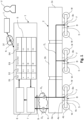
- Figure 1 shows an Example 1 which shows the overall system which may also be called “parts management system”.
- the overall system shown in Figure 1 includes rolling stock, sensors 8a-c, and the computer system 1 ("parts management server").
- the data measured by the sensors 8a-c may be, as discussed above, any kind of physical parameters, and, for example, vibrations and/or the strain of monitored parts 4a-c as well as the payload of a car 3a-c.
- the computer system 1 includes the above described 'parts information database' (database) 5, 'the registered part matching section' (matching section/unit) 7, and 'the duty calculation section' (condition determination section/unit) 6.
- the term "duty" may be used as well in this context.
- the database 5 stores information of (monitored) parts 4a-c and the specific vehicle 2 at which these parts 4a-c are installed, and the total duty 54 of the parts 4a-c.
- the data measured by the sensors 8a-c and the operation data D o including, e.g., train name in the form of a train/vehicle identifier 52, car number as a car identifier 53, and mileage are sent to 'the parts management system' by a network N during the train's operation or when the train comes to the depot, and they are inputted to 'the registered part matching section'.
- the matching section 7 reads the information of the parts 4a-c from the database 5 and compares the information with the operation data D o , which may include the name or the number of the train or the car (the respective identifiers), and identifies the parts 4a-c for which sensor data has been sent/received. After the parts 4a-c are identified, the measured data and the operation data may be inputted to 'the duty calculation section' or condition determination section 6, and the duty/condition of the parts 4a-c in the actual service/running period is calculated using the received data. The calculated duty is added to the total duty of the parts registered in the database 5 and it is re-registered as a new total duty of the parts 4a-c to the database 5.
- the operation data D o which may include the name or the number of the train or the car (the respective identifiers)
- the measured data and the operation data may be inputted to 'the duty calculation section' or condition determination section 6, and the duty/condition of the parts 4a-c in the actual service/
- the operation data D o include the part identifier 51 because there is only a single sensor 8a-c installed at each car 3a-c.
- the monitored part 4a is a suspension S
- the monitored part 4b is a wheel W
- the monitored part 4c is a frame F and the reference signs are placed accordingly in the Figure.
- the operation data D o may be configured based on the vehicle's configuration which shall preferably mean that, in case the vehicle 2 is a train, the train may have one or more cars 3a-b. If the train has only one car 3, the operation data D o of said vehicle 2 do not need to include a car identifier 53 in the operation data D o because the vehicle identifier 52 is sufficient for identification of monitored parts 4a-c if the part identifier 51 is included in the operation data D o as well (if there is more than one monitored part 4a-c in said vehicle 2). Further, if the train has more than one car 3a-c, the operation data D o also include the car identifier 53.
- the operation data D o may also only include said part identifier 51.
- the database 5 may include for each monitored part 4a-c every identifier, i.e. e.g. vehicle, car and part, so that irrespective of the composition of the operation data D o , a monitored part 4a-c can be reliably identified, i.e. its entry in the database 5.
- the entry of a database 5 shall preferably relate to the information provided in one line in the table shown in the Figures 1 et seq. or it shall relate to the value stored in a single cell depending on the context.
- the term "entry" shall be construed accordingly.
- Figure 1 shows an example with a preferred composition of the database 5, where three monitored parts "a” to “c” are included, i.e. entries are present in the database 5, and for each of the monitored parts 4a-c there is included a part identifier stored 51 (the first column in the table of Figure 1 ), a train identifier 52 (the second column in the table of Figure 1 ) and a car identifier 53 (the third column in the table of Figure 1 ). Further, it includes the condition parameter value, which is indicated as total duty 54 in the Figure 1 and which may represent a value of a physical condition or a value of lifetime consumption. As noted before, the entry "54" may also include several values, e.g., by way of an array or the like.
- Figure 1 shows that the computer system 1 can be accessed via a terminal T which may be connected to the computer system 1 wire-based or wireless, e.g. via a network N, such as the internet or an intranet, and the like.
- the terminal T may be used by a user U and the computer system 1 may include a dashboard function (the dashboard providing section is not shown in the drawing) so that the user U can access the database 5 and information stored in the database 5 may be displayed to the user U.
- a schematic representation of the user U who is a human accessing/using the terminal T is shown in Figure 1 as well as in the Figures 2 and 3 .
- the data connection to the computer system 1 is indicated by the arrow having reference sign D T .
- the technical benefit includes that not only the total mileages of parts 4a-c can be taken into consideration for evaluating the total "duty" of a monitored part 4a-c, and the system 1 can evaluate the duty based on various physical values which may affect the (fatigue) condition of the parts 4a-c.
- the system 1 can also evaluate each part's 4a-c total duty even if the train or car where the parts 4a-c are installed change. So when the part 4a-c is reused, the system 1 provides information to assess the condition and possibly the price for parts 4a-c appropriately, reliably and without further inspection or the like, and it may also help decision making for the customer to buy them. It also helps the parts provider, i.e. rolling stock owner, to manage and optimise usage of the parts 4a-c to be able to maintain the condition and the price of the parts as best as possible.
- Figure 2 shows an identical system 1 as explained in connection with Figure 1 , however, the configuration of the vehicle 2 may be different.
- only one car 3a-c on a train has the sensors 8a-c, and the other cars 3a-c of the train do not have sensors 8a-c.
- a middle car 3b may be most suitable to be equipped with the sensors 8a-c.
- the technical benefit is that the number of sensors 8a-c and data lines DL and the related installation costs can be reduced.
- a further example relates to the before discussed examples and especially in case the condition/duty of a monitored part 4a-c is determined based on sensor data D S combined with the load carried by the train, such as passengers and/or freight, i.e. payload.
- the operation data D o shall exclude the payload data, e.g. for reducing data volume, and/or if no extra sensors shall be provided for measuring the payload
- the technical benefit of the above modification is that it can reduce the number of sensors 8a-c and the installation cost to evaluate the duty/condition of a monitored part 4a-c. This can be combined with any other of the examples described herein.
- condition determination section 6 may be included in each vehicle 2 instead of in the computer system 1. This reduces data communication costs because the sensor data D S can be processed directly at the train-side. This is depicted in the schematic drawing of Figure 3 in which the data marked by "D S " in this modification include the condition data evaluated/determined by the condition determination section(s) 6 of the vehicles 2.
- Figure 4 shows an example including a possible dashboard function provided by a dashboard providing section/unit of the computer system 1 which is not shown in the Figures.
- the "dashboard function" shall relate to a specifically arranged format of outputting the information of the database 5 and to display it to a user U at the terminal T and/or at a mobile device 11 (see Fig. 7 ).
- the dashboard function relates to the displayed information 13 (see Fig. 7 ).
- the Figure 7 shows a mobile computing device 11, such as a laptop, a tablet, a smartphone or the like, and it displays a graphical overview of the information included in the database 5.
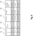
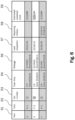
- This may also include further parameters which may be determined by the computer system 1, such as the failure probability, remaining life, the risk calculated by failure probability, the cost impact, or estimated assessed price of the parts apart from the total or estimated condition as shown in Figs. 4 to 6 . This may also help to assess the parts price because the total duty of the part is shown with an understandable value.
- Figure 4 shows a possible option for the displayed information 13 which includes the entries of the database 5 with regard to the identifiers 51 to 53, the total duty 54 and, in addition, an estimated price 55 calculated based on the total duty 54 of each monitored part 4a-c.
- the calculation may, e.g., be an estimate based on historic data about comparable/an identical kind of parts and similar/identical condition/total duty values.
- British Pounds GBP
- the dashboard can display the inspection or the repairing history by including further entries to the database 5.
- the date of the last inspection is additionally saved ("57") and the repair dates are noted (“58") and the lifetime of each part may also be stored as a start date added to the total duty 54 and the mileage 55.
- the data can be provided, e.g., by a user U via the terminal T.
- the computer-executable program code may also be stored in a computer-readable memory that can direct a computer or other programmable data processing apparatus to function in a particular manner, such that the program code stored in the computer readable memory produce an article of manufacture including instruction means which implement the function/act/output specified in the flowchart, block diagram block(s), figures, and/or written description.
- Communication networks generally may include public and/or private networks; may include local-area, wide-area, metropolitan-area, storage, and/or other types of networks; and may employ communication technologies including, but in no way limited to, analog technologies, digital technologies, optical technologies, wireless technologies (e.g., Bluetooth), networking technologies, and internetworking technologies.
- communication technologies including, but in no way limited to, analog technologies, digital technologies, optical technologies, wireless technologies (e.g., Bluetooth), networking technologies, and internetworking technologies.
- a communication message generally may include, without limitation, a frame, packet, datagram, user datagram, cell, or other type of communication message.
- references to specific communication protocols are exemplary, and it should be understood that alternatives may, as appropriate, employ variations of such communication protocols (e.g., modifications or extensions of the protocol that may be made from time-to-time) or other protocols either known or developed in the future.
- Computer-executable program code for carrying out operations of embodiments of the present disclosure may be written in an object oriented, scripted or unscripted programming language such as Java, Perl, Smalltalk, C++, or the like.
- the computer program code for carrying out operations of aspects of the present disclosure may also be written in conventional procedural programming languages, such as the "C" programming language or similar programming languages.
- the computer program may be fixed in any form (e.g., source code form, computer executable form, or an intermediate form) either permanently or transitorily in a tangible storage medium, such as a semiconductor memory device (e.g., a RAM, ROM, PROM, EEPROM, or Flash-Programmable RAM), a magnetic memory device (e.g., a diskette or fixed disk), an optical memory device (e.g., a CD-ROM), a PC card (e.g., PCMCIA card), or other memory device.
- a semiconductor memory device e.g., a RAM, ROM, PROM, EEPROM, or Flash-Programmable RAM
- a magnetic memory device e.g., a diskette or fixed disk
- an optical memory device e.g., a CD-ROM
- PC card e.g., PCMCIA card
Landscapes
- Physics & Mathematics (AREA)
- General Physics & Mathematics (AREA)
- Electric Propulsion And Braking For Vehicles (AREA)
Abstract
Description
- The present disclosure especially relates to a computer system for the monitoring of machine parts wherein the machines are vehicles. The parts of the vehicles can be monitored over their entire lifetime and even if used in different vehicles. The condition of the parts can be determined and tracked in an automated manner.
- The reuse of parts/components of vehicles, especially parts of rolling stock, is increasing also in view of a sustainable operation of vehicles. However, when reusing parts of a vehicle, it is of high importance for the safety of the operation that the condition of the reused part can be assessed with high accuracy and reliability. Further, it is desirable that the condition assessment can be performed quickly and in an automated manner. So far, the inspection and the assessment of the condition of a part can be time-consuming and cumbersome, e.g., when the assessment relies on human visual inspection of the part. There is a patent document with the application number
JP 2005 168203 A - It is an object of the present disclosure to provide an improved computer system for the monitoring of machine parts wherein the machines are vehicles as well as a system including the computer system and one or more vehicles having monitored parts installed. The object is solved by the appended claims.
- The following aspects and preferred modifications are provided in particular:
A computer system, to which it may also be referred as "parts management server". The computer system is configured to monitor/supervise the condition of one or more parts of one or more vehicles. The parts of the vehicle may also be referred to as "supervised part" or "monitored part" and the term part shall entail components, members, units, etc. of the vehicle. For example, in case the vehicle is a train, the parts may include one or more of the motor, inverters and converters, the bogie, sub-parts of the before mentioned parts, control units and the like. The computer system may be a remotely located computer system which communicates with the one or more vehicles by way of, preferably, a wireless data exchange method. The computer system may be located at a single location or it may be a distributed computer system (at least partially), such as in a cloud or the like. - The computer system may include and/or may be connected to a storage unit. The storage unit may store information in one or more databases. The database stores, at least, information about monitored parts of the vehicles which are connected with the computer system. Said information concern, in particular, one or more condition parameter(s). A condition parameter indicates the condition of the monitored part. The term "condition" may entail different information and it may be characterized by a single value or a set of values which will be explained later. In general, the condition parameter shall be understood, preferably, to represent and indicate the state/condition of the monitored part, for example, in view of its wear, load history, expectable remaining service time (lifetime) or the like.
- Further, the computer system, preferably, has one or more interface units which are input/output interfaces for the receipt or the transmission of data from/to another unit/section. The interface unit may also be replaced by any other suitable means which allows the computer system and the sections described below to receive (and/or to transmit to) data from the vehicles. The interface unit may be physical hardware and/or software. For example, the interface unit receives the operation data from one of the vehicles communicably connected to the computer system as well as sensor data from the vehicle. The sensor data are recorded/measured by one or more sensors which are installed at the vehicle. The operation data include, at least, one identifier which enables a matching section (described below) to match the part to which the sensor data belong with the respective database entry of said very part. There may be different identifiers which depends on the configuration of the vehicle and the number of sensors installed at each vehicle. Also, this will be explained later.
- Further, the interface unit(s) may provide the received data from the vehicle to the designated other sections (units) of the computer system; especially, the operation data may be preferably provided to the matching section and the sensor data are provided to a condition determination section. In another example, the operation data and the sensor data may be provided to the matching section by the interface unit and the matching section transmits the data to a condition determination section after it has finished the matching processing.
- The before mentioned matching section (also called "registered part matching section") is configured to identify the monitored parts from/about which the interface unit has received sensor data by comparing received operation data with information stored in the database. As noted above, the matching section compares information received by way of the operation data from the vehicle with entries in the database so as to find the entry of a monitored part which matches with/belongs to the sensor data received. Preferably, this matching is carried out by way of comparing identifiers stored in the database with identifiers provided in the operation data accompanying the received sensor data. Hence, preferably, the database stores not only the condition parameter value, but identifier(s) as well so that the matching can be done in a computational inexpensive manner. The result of the matching can be passed by the matching section to a condition determination section so that the condition determination section is informed about to which part the sensor data belong.
- Further, the computer system preferably includes a condition determination section which is configured to read a value of the condition parameter of an identified monitored part from the database for which sensor data have been received. In another example the condition determination section may be placed in the vehicles instead of the computer system. With regard to the configuration of the condition determination section, for example, if the matching section has identified the monitored part "A" for which sensor data have been received, the condition determination section reads the condition parameter value which is stored in the database for said monitored part "A" as the actual or old value. Then, the determination section is further configured to update the (actual/old) value of the condition parameter based on the sensor data received for said monitored part and to overwrite the value of the condition parameter with the updated value of the condition parameter in the database, i.e. the new value is entered in the database which replaces the "old" value.
- The above enables that parts of a vehicle can be monitored in an automated fashion, individually and over the entire lifetime. Even if the parts are reused in other vehicles, the part can be identified and the actual condition thereof can be quickly and reliably read from the central database; and which can be performed automatically. This may help operators of a vehicle to identify parts which need repair or maintenance or which have reached their maximum lifetime. Even further, if an operator intends to sell a part or another operator intends to buy a part, the condition information may be useful for finding a fair price reliably. Preferably, the different identifiers and especially the part identifiers which may be used for a comparison in the matching section may be used uniquely for each part so that the lifetime tracking is even more reliable and even less complex.
- Further, the condition parameter may be an accumulated load of a monitored part. The condition or the accumulated load of the monitored part may also be called "duty" in the preferred meaning that the duty shall relate to an accumulated load history. For the determination of said accumulated load, the condition determination section may be configured to determine a value of an additional load of a monitored part. The determination may be carried out by using/based on the received sensor data. Further, the condition determination section may be configured to determine the updated value of the condition parameter by adding the determined additional load to the (old/actual) value stored in the database.
- The determination is reliable, computationally inexpensive because only a few computing steps are necessary and it enables to track the condition of a part over its entire life with accuracy. The centrally stored information is available from every position which has connection to the internet or another network connected to the computer system and the information stored in the database is also very reliably in view of the fact that it cannot be altered except by way of the operations of the computer system. The write access to the database may be restricted to very few users or it may be restricted for every user and only available to the computer-based routines carried out by the determination condition section.
- With regard to the term "load": The term shall entail all possible "load" scenarios including, but not exclusively, mechanical loads, electrical loads, temperature variations, and the like. It is not necessary that the condition is defined by a single value. For example, the condition may also be defined by a set of values, such as a vector. Further, a single value may be used, however, computed with the input of different kinds of loads (or a single load). In case a single value is computed based on the input of different loads: This may be the case when a monitored part is monitored by more than one sensor which are different, e.g. one sensor for vertical forces acting on the part and one sensor for the strain induced into the part. Then, the condition value "accumulated load" or "duty" may also be computed based on a combination of the input of the different sensors. The computation may be performed based on known principles of general mechanics, fracture mechanics, electrical engineering (in case of electrical loads), applied physics, thermodynamics, and the like. A non-limiting simple example may, for example, relate to the load cycles of a mechanical monitored part wherein a sensor may be installed at the monitored part which records the loads (or load changes) on said part and the accumulated load may indicate the total number of load cycles which the part has endured to date.
- The condition of the monitored part may be determined by one or more physical parameters which may be measured by the one or more sensors of the vehicle or installed at the vehicle, and/or which are determined by computer analysis. The physical parameters may include, as discussed above, mechanical forces, mechanical moments, mechanical vibrations, pressure, temperature, electrical currents, rotational movements, magnetic fluxes and/or the like. The computer analysis preferably encompasses the computer-based determination of loads instead of using a measurement sensor which can reduce the number of sensors that need to be installed at a vehicle. For example, with regard to the determination of a total distance run by a vehicle, a sensor may be used which directly measures the distance. Alternatively, a sensor may be used which only measures a part of the information needed, and the distance is then determined by a computer using said information, e.g. a geolocation sensor may provide such information. Even further, alternatively, no sensor may be used for some kind of "loads" such as the distance run (mileage) by the vehicle; e.g. in case of the distance it may also be determined based on travelling schedules, e.g., if the vehicle is a train of a public transportation vehicle.
- The range of possible loads being fed into the computer system for determining a state/condition of a monitored part provides high flexibility so that many different parts of a vehicle can be monitored in an automated manner adding synergistically to the above technical benefits.
- Further, the condition determination section may be configured to determine, based on the value of the condition parameter/accumulated load, a lifetime consumption of the monitored part by comparing the value of the condition parameter with a predefined maximum value. Further or instead, the lifetime consumption may also be a time interval until the next repair, maintenance or replacement is needed. The lifetime consumption may be expressed, e.g., by way of a percentage value or the like. For example, the lifetime consumption may indicate how much of the maximum use of a part is already reached, e.g. 70% may indicate that 30% of the maximum lifetime (or until the next service) of the part are left. The lifetime consumption may be a dimensionless number calculated by dividing the actual accumulated load value and the maximum value.
- More specifically, for example, in case the vibrational load of a part shall be used for determining the accumulated load, a sensor may detect the vibrations acting on a part and the maximum of vibration cycles or the like which are predefined for a part (e.g. said information may be provided by the manufacturer or by a theoretical/simulation analysis or the like) may be compared to the accumulated vibration cycles measured so far. Another example may relate to the number of load changes which may be measured by a sensor and compared to a maximum number. Another example may relate to the weight/forces acting on a part and it may be determined the number of occasions when a load is above a predetermined weight/force threshold and said number may be compared to a maximum high/over load value. Even further, a rotating part may be monitored by a sensor in view of the number of rotations it has performed and compared to a maximum number. Also, the maximum value may be a time combined with another physical parameter. For example, the maximum value may relate to the maximum time a rotating part may be operated at a certain rotational speed or the maximum time a mechanical part may bear a certain load, or the like.
- The use of a lifetime consumption value allows a quick and reliable estimate about the condition of a monitored part which can be computerized inexpensively.
- Further, in case the accumulated load value includes a mechanical and/or electrical load of the monitored part, the load may be determined based on a measurement of said mechanical and/or electrical load performed by a respective sensor installed at the vehicle. For example, if the accumulated load value shall indicate a mechanical wear of the monitored part in view of load change cycles, the sensor may be a load cell or a strain gauge or the like which provides the measurement information about the load changes of the monitored part. The term "includes" above shall entail the meaning in this context, preferably, that the mechanical and/or electrical load may not be the only "load" indicated by the accumulated load.
- More specifically, as an example, the mechanical/electrical load may be combined with another kind of load, such as the total mileage/distance run by the vehicle and the accumulated load may then be a dimensionless value being determined from a weighted input from the measured mechanical/electrical load(s) and the distance total covered by the vehicle. Even more specifically, as one of many possible examples, the accumulated load may be determined based on the information that the vehicle has a total mileage of x-thousand kilometers which is weighted with 30% and the other 70% are the mechanical load measured by the sensor(s), e.g. number load change cycles.
- Further, the accumulated load value may be the total mileage/total distance of the vehicle (run/driven by the vehicle) or a car being part of the vehicle. Alternatively, as discussed above, the accumulated load value may be a combination of the mileage and any other load, such as vibrations or the like. The mileage/total distance run may be measured by a sensor, such as a geolocation sensor, e.g. GPS or Galileo, and/or the mileage may be part of the operational data transmitted to the computer system. The accumulated load may be updated every predefined use cycle of the vehicle by adding the additional distance driven during the last use cycle, and the computer system may be configured to perform a computer analysis (or any kind of determination or calculation operation) for determining the lifetime consumption of a monitored part by comparing the mileage value with a predefined maximum total mileage value. A use cycle of a vehicle may be defined as each trip, predefined time intervals, or the like. Specifically, in case of a train, each use cycle may be a trip between each station or the entire distance covered during one day or the like.
- Further, the accumulated load value may be the total weight of load (here "load" shall relate to the payload instead of mechanical/electrical/thermal loads discussed before) carried by the vehicle, or a combination of the total weight and any other physical parameter. The accumulated load may be updated every predefined use cycle of the vehicle by adding the additional weight load carried during the last use cycle, and the computer system may be configured to perform determining the lifetime consumption of a monitored part by comparing the total weight load value with the predefined maximum total weight value. For example, it may be determined that certain parts of a freight train shall be inspected after a total of a predetermined tons of freight transported and this could be reliably tracked by the above accumulated load value example by summing up the freight weight transported in the database. Again, also the total weight of the payload may be combined with other "loads" of the vehicle/monitored part measured by the sensors.
- Further, the weight of the freight and/or of the passengers (payload) carried by the vehicle can be determined by computer analysis. In this case, it is possible that no sensor is used/installed at the vehicle for measuring the weight. Instead, for example, the payload may be determined based on other sources of information, such as ticket sales, freight documents, or the like which are then used to calculate the weight in the computer. This reduces the system complexity because generally available information can be used not only for their original purpose, e.g. ticket sales, but at the same time said information can also be used for determining the condition.
- Further, the sensors/sensor devices employed may include any kind of sensors for measuring physical parameters and the like. Preferably, e.g., the sensors include load cells for determining mechanical loads, electrical current sensors or the like for electrical parameters, rotational sensors for measuring the number of rotations, rotational speed, etc. and other sensors. The sensors herein may also entail geolocation sensors, e.g., for determining a travelling distance and the like.
- Further, the database may store, for each monitored part, a part identifier, a vehicle identifier and/or a car identifier, and the operation data received from a vehicle may include a vehicle identifier of the vehicle, a car identifier and/or a part identifier. Preferably, the database has the option to store as many different identifiers as possible even if not used for each vehicle. For example, if a plurality of different vehicles is monitored by the computer system, some vehicles may be equipped with a single sensor only and it is sufficient to transmit the vehicle identifier in the operational data for said vehicles, while other vehicles may have a plurality of sensors so that the part identifier may be submitted in addition to the vehicle identifier, and even other vehicles may have a plurality of cars and each car may include a sensor so that a car identifier would be necessary. Therefore, the set of identifiers which are compared with the entries in the database may be adapted to the type and kind of equipment of the vehicle.
- Preferably, the operational data sent by a vehicle determine as to how the matching is performed. E.g., in case the vehicle has only a single car and only a single sensor, the operational data of said vehicle only include the vehicle identifier and, thus, the matching section will only compare this vehicle identifier to vehicle identifiers stored in the database. If, however, the vehicle is a train with many cars and each car being equipped with a single sensor, the operational data of such vehicle may include a car identifier in addition to the vehicle identifier and the comparison may use both kinds of identifiers for identifying the correct part in the database. In other words, the operational data may include the number and kinds of identifiers such that the matching section can identify the correct part/entry in the database reliably. Such a configuration of the database and the operation data offers high flexibility for the use of the computer system to monitor very differently configured vehicles. In other words, the setup of a vehicle and its sensors is not limited by the computer system which shall monitor the vehicle or parts thereof.
- In even other words, in view of the operation data, depending on the configuration of each vehicle, the operation data may be configured differently. The configuration of each vehicle may be different. Preferably the vehicles are trains or automobiles. In case of a train, each train may have a plurality of cars which are connected to each other and for each car there may be one or more monitored parts which may be monitored by one or more sensors.
- If the vehicle is a train with a plurality of cars it may be an especially preferred option that only a single car has a single sensor device and for the other cars the accumulated load/condition parameter is estimated based on the values of the single sensor. This reduces the number of sensors and electrical connections which are needed for a vehicle and contributes to reducing the system complexity. The single sensor in this preferred option may be placed at a front car of a train which may be assumed to have the highest loads of all cars or in a middle car if the train is used in different driving directions often so as to receive the most representative value for the condition parameter.
- The technical advantage of the matching section and the use of the different identifiers is further, that the volume of data being transmitted from the vehicles, which usually dynamically change their position and which may also operate in areas of reduced/impaired wireless data transfer possibilities, can be kept relatively small. The operation data and especially the identifier information can be merged with the data of the sensors into combined data packets without increasing the size/volume of the sensor data a lot. In other words, the reliability of the herein described computerized monitoring system can also be ensured, even if the monitored parts are used in vehicles which operate in remote areas without a good wireless internet connection or the like. This further adds synergistically to the overall technical benefits of the herein described aspects and especially to the improvement of reliability and the option to provide an automated and quick assessment of a monitored part over its entire lifetime.
- Another aspect may relate to a system including the computer system as described above and one or more vehicles, wherein the one or more vehicles may each be a train and each train may have one or more cars. The one or more trains may be connected to the remotely located computer system wireless so that data can be exchanged, the data may include the operation data and the sensor data. Instead of trains, the vehicles may also be automobiles.
- The system allows to monitor with low system complexity a large number of vehicles and parts thereof, wherein even an exchange of parts does not impair the monitoring of the parts because the matching section of the computer system can reliably and computerized identify each part irrespective where it is used.
- Further, the condition determination section may be provided in each train and the condition determination may be performed in each train and the determination result may be transmitted to the computer system. In this case, the remote computer system is reduced further in view of complexity and hardware resources needed, while the vehicles usually available internal computer units may be used for the condition determination. The data volume transferred to the remote computer system is also further reduced because only the value of the condition parameter and the operation data, especially the identifiers may need to be transferred which have a data size, such as few bytes or kilobytes. This enables the use of the system even for areas with a less well-equipped wireless data transfer infrastructure and it also reduces the time for the data transfer so that the database includes more or less "real-time" information.
- Further, if the vehicle is a train, the parts of the vehicle which are monitored may include, preferably, the bogie parts of the train including one of a frame, a suspension, a shaft, a wheel, a bearing, a gearbox, and/or a motor. Other parts may be headline pantographs, converters and inverters, and the like. With regard to the electric machines, such as inverters and converters as well as control boxes or the like, it may be further of interest to also monitor the temperature load or electric current load, etc.
- Further, each monitored part may have a QR code placed thereon and, when scanned, the user who scans the code receives information about the value of the condition parameter or the like. For example, this may be realized by a smartphone or any other mobile device which has an internet connection and the QR code may include a link to the database in the remotely and internet-connected computer system/database. This allows to provide that relevant information about the monitored parts can also be obtained by decentral access on each site. For example, a user may not access a computer or the like to obtain the information from the database.
- Further, the vehicle and/or the computer system may include a dashboard function unit which can provide to display various information to a user. A terminal may be provided with the computer system and/or the vehicle for displaying a dashboard on a screen. Preferably, it can display the value of the condition parameter, a probability of failure of a monitored part, a remaining life time, and/or estimated selling price, a risk of failure, the mileage, an inspection history, and the like. Further, it may also provide advice to an owner about a recommended use. In regard of the latter, e.g., the recommended use may include optimal intervals of inspection and maintenance, maximum loads, or the like for keeping the part in an optimal condition for a long time. In case the data is not saved in the database, a computing unit of the computer system may calculate the required data before displaying it.
- Summarizing, the disclosure including the above examples and modifications all enable that parts of a vehicle can be monitored in an automated fashion, individually and over the entire lifetime. Even if the parts are reused in other vehicles, the part can be identified and the actual condition thereof can be quickly and reliably read from the central database; and which can be performed automatically. This may help operators of a vehicle to identify parts which need repair or maintenance or which have reached their maximum lifetime. Even further, if an operator intends to sell a part or another operator intends to buy a part, the condition information may be useful for finding a fair price reliably. Preferably, the different identifiers and especially the part identifiers which may be used for a comparison in the matching section may be used uniquely for each part so that the lifetime tracking is even more reliable and even less complex.
-
- Fig. 1
- shows schematically a system as described herein.
- Fig. 2
- shows schematically a modification of a system as described herein.
- Fig. 3
- shows schematically another modification of a system as described herein.
- Figs. 4-6
- show information which included in a database and/or displayed to a user.
- Fig. 7
- shows a user's mobile device accessing about information a monitored vehicle.
- In the following, preferred aspects and examples will be described in more detail with reference to the accompanying figures. Same or similar features in different drawings and examples are referred to by similar reference numerals. It is to be understood that the detailed description below relating to various preferred aspects and preferred examples are not to be meant as limiting the scope of the present disclosure.
-
Figure 1 shows an example of the system as described herein including thecomputer system 1 which is connected by a wireless connection to a train being an example of avehicle 2. The train in the present example has threecars 3a-c, however, there can be more orless cars 3 per train. Eachcar 3 is shown by way of a schematic and, especially, a bogie B is shown percar 3 which has wheels W, a frame F, a suspension S and asensor 8a-c attached to each bogie B. Saidsensors 8a-c may be various kinds of sensors, such as a load cell, an electricity sensor, a strain sensor, and the like with which mechanical forces including vibrations and load alternations, electrical currents/voltages, and the like are measured depending on which physical property of a monitoredpart 4a-c of acar 3 shall be monitored. The monitoredparts 4a-c may, for example, include the before described bogie B, frame F, wheels W, suspension S and other parts of thecars 3a-c. - The sensors (sensor devices) 8a-c are connected to a transmitter (not shown) which provides the data measured by the
sensors 8a-c to thecomputer system 1, wherein the data may be transferred by wire or wireless within the train and wireless from the train to the remotely locatedcomputer system 1. The transfer of the data is indicated by the bold arrowed lines DL connectedsensors 8a-c with thecomputer system 1. - Further, the train may transmit so-called "operation data" Do to the
computer system 1. The operation data Do may include various information and preferably the operation data Do include identifier (identifier data) which can be used by thecomputer system 1 to track and identify from which part/sensor the measurement data Ds of thesensors 8a-c are provided. In other words, the identifier(s) included in the operation data Do especially serve to provide/enable a matching function within thecomputer system 1 which allows to identify the correct monitoredpart 4a-c for which measurement data DS from one ormore sensors 8a-c was received by thecomputer system 1. This allows to track the condition/state of a monitoredpart 4a-c over an entire lifetime with certainty and reliably because only the sensor data DS which belongs to a specificmonitored part 4a-c is associated with said monitoredpart 4a-c in adatabase 5 of thecomputer system 1. - The
computer system 1 described herein is remotely located to thevehicles 2 which are monitored and it may be a server, a server farm, it may be provided by distributed cloud-resources and the like. With the reception of data transmitted from one or more of thevehicles 2 at an interface unit (s) 9, the data is entered into thecomputer system 1 and it is distributed to different units thereof, preferably. That means, the operation data Do is preferably provided to amatching section 7 and the measured sensor data DS is provided to acondition determination section 6. However, other ways of data distribution are possible, such as providing all received data to thematching section 7, firstly, before further distribution/processing is carried out. Thematching section 7 is configured to match information included in the received operation data Do with relevant information in thedatabase 5 which is also a part of thecomputer system 1. Especially, thematching section 7 compares one or more identifiers included in the operation data Do received from avehicle 2 with respective identifiers stored in thedatabase 5. If identifiers are found in thedatabase 5 which match with them received in the operation data Do, thematching section 7 has identified the entry in thedatabase 5 for which measured sensor data have been received at thecomputer system 1 in parallel. - Here it is noted that there are different options for transmitting the operation data and the sensor data. For example, the operation data Do and the sensor data Ds may be transmitted in parallel in different data streams/data signals and possibly also by different emitters (not shown) from a
vehicle 2 to thecomputer system 1. Further, for example, avehicle 2 may have a single emitter which transmits only a single data signal which includes the operation data Do and the corresponding sensor data Ds at once/in the same signal. For example, the signal may include the payload part including the sensor data Ds and a header part or the like for including the operation data Do. Further, the sensor data Ds may be modified before the transmission by, e.g., including information which allows to identify which sensor data DS belongs to which operation data Do. However, instead of such a modification it is also possible to "link" the operation data Do and the measured signal data DS by way of the transmission timing or the timing of the receipt, e.g., thecomputer system 1 may be configured to assume that data which is received at the same time from asame vehicle 2 belongs together or data which was sent at the same time (including a time stamp). - After the entry of the
database 5 which matches with the identifiers of the operation data Do is found, it is possible to read a condition parameter (or a plurality thereof) from thedatabase 5 which are related to the monitoredpart 4a-c for which (new) sensor data DS have been received. Thecondition determination section 6 determines a value(s) of one or more condition parameter based on the new sensor data DS and the condition parameter value read from thedatabase 5. This, for example, is done by adding further loads to the old/actual value in thedatabase 5 and the loads are determined or provided by the sensor measurement data DS. As one example, if the sensor (measurement) data DS include vibrations from arespective sensor 8a-c which is attached to a bogie B or a frame F of a train, the vibrations may be used to determine a condition. Further in this example, there may be theoretically known, simulated or otherwise determined maximum values which are predefined for said monitored bogie B or frame F of the train as to how many vibrations having a certain amplitude and/or frequency said part can bear until the part needs to be repaired or exchanged. Then, if the condition parameter would indicate the total number of vibrations endured so far and if the newly received sensor data include additional vibration events, the actual value of the condition parameter may be updated by adding the additional vibrations to the actual/old value. - Even further, the
condition determination section 6 can compare the predefined maximum value with the actual value to provide a percentage for the lifetime consumption of said monitoredpart 4a-c, e.g. the lifetime consumption in this example would indicate how much (in percent) of the maximum value is already consumed/reached. The lifetime consumption value may be additionally stored in thedatabase 5 or instead of the absolute value of a condition parameter. Further, the lifetime consumption value may be composed of many different condition parameters, such as vibrations, mechanical strain, load change events, and the like. After thecondition determination section 6 has updated the condition parameter(s), another entry of thedatabase 5 may be updated or thecomputer system 1 may hibernate for a predefined period to save electrical energy, i.e. it may also perform the tasks periodically by only receiving data for a certain period and by only performing the matching and determination tasks every predefined interval en bloc. - In other words,
Figure 1 shows an Example 1 which shows the overall system which may also be called "parts management system". The overall system shown inFigure 1 includes rolling stock,sensors 8a-c, and the computer system 1 ("parts management server"). The data measured by thesensors 8a-c may be, as discussed above, any kind of physical parameters, and, for example, vibrations and/or the strain of monitoredparts 4a-c as well as the payload of acar 3a-c. Thecomputer system 1, in particular, includes the above described 'parts information database' (database) 5, 'the registered part matching section' (matching section/unit) 7, and 'the duty calculation section' (condition determination section/unit) 6. As noted before, instead of condition or instead of lifetime consumption, the term "duty" may be used as well in this context. - The
database 5 stores information of (monitored)parts 4a-c and thespecific vehicle 2 at which theseparts 4a-c are installed, and thetotal duty 54 of theparts 4a-c. The data measured by thesensors 8a-c and the operation data Do including, e.g., train name in the form of a train/vehicle identifier 52, car number as acar identifier 53, and mileage are sent to 'the parts management system' by a network N during the train's operation or when the train comes to the depot, and they are inputted to 'the registered part matching section'. Thematching section 7 reads the information of theparts 4a-c from thedatabase 5 and compares the information with the operation data Do, which may include the name or the number of the train or the car (the respective identifiers), and identifies theparts 4a-c for which sensor data has been sent/received. After theparts 4a-c are identified, the measured data and the operation data may be inputted to 'the duty calculation section' orcondition determination section 6, and the duty/condition of theparts 4a-c in the actual service/running period is calculated using the received data. The calculated duty is added to the total duty of the parts registered in thedatabase 5 and it is re-registered as a new total duty of theparts 4a-c to thedatabase 5. In the example ofFigure 1 it is not necessary that the operation data Do include thepart identifier 51 because there is only asingle sensor 8a-c installed at eachcar 3a-c. Further, in this example, the monitoredpart 4a is a suspension S, the monitoredpart 4b is a wheel W, and the monitoredpart 4c is a frame F and the reference signs are placed accordingly in the Figure. - With regard to the
database 5 and the operation data Do further configurations are possible and preferred. The operation data Do may be configured based on the vehicle's configuration which shall preferably mean that, in case thevehicle 2 is a train, the train may have one ormore cars 3a-b. If the train has only onecar 3, the operation data Do of saidvehicle 2 do not need to include acar identifier 53 in the operation data Do because thevehicle identifier 52 is sufficient for identification of monitoredparts 4a-c if thepart identifier 51 is included in the operation data Do as well (if there is more than one monitoredpart 4a-c in said vehicle 2). Further, if the train has more than onecar 3a-c, the operation data Do also include thecar identifier 53. Further, in case that eachpart 4a-c in allvehicles 2 monitored by thecomputer system 1 should have a unique part identifier, the operation data Do may also only include saidpart identifier 51. Further, thedatabase 5 may include for each monitoredpart 4a-c every identifier, i.e. e.g. vehicle, car and part, so that irrespective of the composition of the operation data Do, amonitored part 4a-c can be reliably identified, i.e. its entry in thedatabase 5. It is noted that the entry of adatabase 5 shall preferably relate to the information provided in one line in the table shown in theFigures 1 et seq. or it shall relate to the value stored in a single cell depending on the context. However, if the data in thedatabase 5 should be arranged differently, e.g., not by way of a table, the term "entry" shall be construed accordingly. -
Figure 1 shows an example with a preferred composition of thedatabase 5, where three monitored parts "a" to "c" are included, i.e. entries are present in thedatabase 5, and for each of the monitoredparts 4a-c there is included a part identifier stored 51 (the first column in the table ofFigure 1 ), a train identifier 52 (the second column in the table ofFigure 1 ) and a car identifier 53 (the third column in the table ofFigure 1 ). Further, it includes the condition parameter value, which is indicated astotal duty 54 in theFigure 1 and which may represent a value of a physical condition or a value of lifetime consumption. As noted before, the entry "54" may also include several values, e.g., by way of an array or the like. - Further,
Figure 1 shows that thecomputer system 1 can be accessed via a terminal T which may be connected to thecomputer system 1 wire-based or wireless, e.g. via a network N, such as the internet or an intranet, and the like. The terminal T may be used by a user U and thecomputer system 1 may include a dashboard function (the dashboard providing section is not shown in the drawing) so that the user U can access thedatabase 5 and information stored in thedatabase 5 may be displayed to the user U. A schematic representation of the user U who is a human accessing/using the terminal T is shown inFigure 1 as well as in theFigures 2 and3 . The data connection to thecomputer system 1 is indicated by the arrow having reference sign DT. - As explained before, the technical benefit includes that not only the total mileages of
parts 4a-c can be taken into consideration for evaluating the total "duty" of a monitoredpart 4a-c, and thesystem 1 can evaluate the duty based on various physical values which may affect the (fatigue) condition of theparts 4a-c. Thesystem 1 can also evaluate each part's 4a-c total duty even if the train or car where theparts 4a-c are installed change. So when thepart 4a-c is reused, thesystem 1 provides information to assess the condition and possibly the price forparts 4a-c appropriately, reliably and without further inspection or the like, and it may also help decision making for the customer to buy them. It also helps the parts provider, i.e. rolling stock owner, to manage and optimise usage of theparts 4a-c to be able to maintain the condition and the price of the parts as best as possible. - Further examples as to preferred configurations of the herein described
system 1 will be explained in the following. -
Figure 2 shows anidentical system 1 as explained in connection withFigure 1 , however, the configuration of thevehicle 2 may be different. In this example, only onecar 3a-c on a train has thesensors 8a-c, and theother cars 3a-c of the train do not havesensors 8a-c. - As explained for Example 1, when the sensor data DS and the operation data Do are sent to the
computer system 1, thecomputer system 1 determines the condition of each monitoredpart 4a-c in the train. The condition of the monitoredparts 4a-c installed in thecars 3a-c withoutsensors 8a-c is evaluated to be the same as the condition of the respective monitoredparts 4a-c installed in thecar 3a-c with thesensors 8a-c because if the train runs the same track in a period the condition can be assumed to be the comparable/same for everycar 3a-c in the train. Especially, this is the case if the front-runningcar 3a is used as the sensor-equippedcar 3 because it may be especially representative for the load profile. Otherwise, if the daily use of the train includes many changes of driving direction, amiddle car 3b may be most suitable to be equipped with thesensors 8a-c. The technical benefit is that the number ofsensors 8a-c and data lines DL and the related installation costs can be reduced. - A further example relates to the before discussed examples and especially in case the condition/duty of a monitored
part 4a-c is determined based on sensor data DS combined with the load carried by the train, such as passengers and/or freight, i.e. payload. If the operation data Do shall exclude the payload data, e.g. for reducing data volume, and/or if no extra sensors shall be provided for measuring the payload, the payload may be determined by thecomputer system 1 based on the number of passengers (Np), the average weight of a human (Wa) and the number of cars (Nc) on the train, e.g. by Eq. 1.
- The technical benefit of the above modification is that it can reduce the number of
sensors 8a-c and the installation cost to evaluate the duty/condition of a monitoredpart 4a-c. This can be combined with any other of the examples described herein. - In a further modification of the herein described examples, the
condition determination section 6 may be included in eachvehicle 2 instead of in thecomputer system 1. This reduces data communication costs because the sensor data DS can be processed directly at the train-side. This is depicted in the schematic drawing ofFigure 3 in which the data marked by "DS" in this modification include the condition data evaluated/determined by the condition determination section(s) 6 of thevehicles 2. - Further,
Figure 4 shows an example including a possible dashboard function provided by a dashboard providing section/unit of thecomputer system 1 which is not shown in the Figures. The "dashboard function" shall relate to a specifically arranged format of outputting the information of thedatabase 5 and to display it to a user U at the terminal T and/or at a mobile device 11 (seeFig. 7 ). In other words, the dashboard function relates to the displayed information 13 (seeFig. 7 ). For example, theFigure 7 shows amobile computing device 11, such as a laptop, a tablet, a smartphone or the like, and it displays a graphical overview of the information included in thedatabase 5. This may also include further parameters which may be determined by thecomputer system 1, such as the failure probability, remaining life, the risk calculated by failure probability, the cost impact, or estimated assessed price of the parts apart from the total or estimated condition as shown inFigs. 4 to 6 . This may also help to assess the parts price because the total duty of the part is shown with an understandable value. -
Figure 4 shows a possible option for the displayedinformation 13 which includes the entries of thedatabase 5 with regard to theidentifiers 51 to 53, thetotal duty 54 and, in addition, an estimatedprice 55 calculated based on thetotal duty 54 of each monitoredpart 4a-c. The calculation may, e.g., be an estimate based on historic data about comparable/an identical kind of parts and similar/identical condition/total duty values. Here the value in "British Pounds" (GBP) is not explicitly displayed in the Figures. - Further, as shown by
Figure 5 , another example may include that the dashboard shows further values, such as thetotal mileage 56 of theparts 4a-c apart from thetotal duty 54 of theparts 4a-c as a reference and the dashboard also shows when thesensors 8a-c were installed as shown inFig.5 . This is included in the same cell as thetotal duty 54 inFigure 5 , as an example. However, the installation date may also be saved separately. The technical benefit is that even if thesensors 8a-c are not attached to thecar 3a-c from the scratch, the total mileage ofparts 4a-c experienced becomes an indicator to assess the condition. - Further, as shown by
Fig. 6 the dashboard can display the inspection or the repairing history by including further entries to thedatabase 5. Here, e.g., the date of the last inspection is additionally saved ("57") and the repair dates are noted ("58") and the lifetime of each part may also be stored as a start date added to thetotal duty 54 and themileage 55. The data can be provided, e.g., by a user U via the terminal T. - Further,
Fig. 7 shows the use of QR codes 10 which may be provided/attached to the monitoredparts 4a-c. When the QR code 10 is read by amobile computing device 11, the user U can access thecomputer system 1 and confirm/display the relevant/requested information from thedatabase 5. - Further,
computer system 1 and the terminal T can be used to provide advice to an owner of avehicle 2. For example, thecomputer system 1 may provide advice as to the optimal usage ofparts 4a-c or the optimal repair/inspection/exchange intervals to maintain the monitoredparts 4a-c in a good condition for a long time. - Again, as described above, preferably, the
vehicles 2 are trains and preferred monitoredparts 4a-c relate toparts 4a-c of the train, such as the bogie B and parts thereof including frame F, suspension S, shaft (not shown), wheel W, gearbox (not shown), motor (not shown). Other parts may be included, as well, such as converters and inverters, pantographs, control units installed in a train or automobile, and the like. - Summarizing, the disclosure, among other advantages described above, enables to monitor various kinds of
parts 4a-c of avehicle 2 in a fully automated manner and the estimated condition of the monitored parts is reliably available for a human user U of the system. - As will be appreciated by one of skill in the art, the present disclosure, as described hereinabove and the accompanying figures, may be embodied as a method (e.g., a computer-implemented process or any other process), apparatus (including a device, machine, system, computer program product, and/or any other apparatus), or a combination of the foregoing. Aspects/Examples of the present disclosure may be a software entirely (including firmware, resident software, micro-code, etc.), or a combination of software and hardware aspects that may be referred to as a "system". Furthermore, the present disclosure may take the form of a computer program product on a computer-readable medium having computer-executable program code embodied in the medium.
- It should be noted that arrows may be used in drawings to represent communication, transfer, or other activity involving two or more entities. Double-ended arrows generally indicate that activity may occur in both directions (e.g., a command/request in one direction with a corresponding reply back in the other direction, or peer-to-peer communications initiated by either entity), although in some situations, activity may not necessarily occur in both directions.
- Single-ended arrows generally indicate activity exclusively or predominantly in one direction, although it should be noted that, in certain situations, such directional activity actually may involve activities in both directions (e.g., a message from a sender to a receiver and an acknowledgement back from the receiver to the sender, or establishment of a connection prior to a transfer and termination of the connection following the transfer). Thus, the type of arrow used in a particular drawing to represent a particular activity is exemplary and should not be seen as limiting.
- The present disclosure may be described with reference to flowchart illustrations and/or block diagrams of methods and apparatuses, and with reference to a number of sample views of a graphical user interface generated by the methods and/or apparatuses. It will be understood that each block of the flowchart illustrations and/or block diagrams, and/or combinations of blocks in the flowchart illustrations and/or block diagrams, as well as the graphical user interface, can be implemented by computer-executable program code.
- The computer-executable program code may be provided to a processor of a general purpose computer, special purpose computer, or other programmable data processing apparatus to produce a particular machine, such that the program code, which executes via the processor of the computer or other programmable data processing apparatus, create means for implementing the functions/acts/outputs specified in the flowchart, block diagram block or blocks, figures, and/or written description.
- The computer-executable program code may also be stored in a computer-readable memory that can direct a computer or other programmable data processing apparatus to function in a particular manner, such that the program code stored in the computer readable memory produce an article of manufacture including instruction means which implement the function/act/output specified in the flowchart, block diagram block(s), figures, and/or written description.
- The computer-executable program code may also be loaded onto a computer or other programmable data processing apparatus to cause a series of operational steps to be performed on the computer or other programmable apparatus to produce a computer-implemented process such that the program code which executes on the computer or other programmable apparatus provides steps for implementing the functions/acts/outputs specified in the flowchart, block diagram block(s), figures, and/or written description. Alternatively, computer program implemented steps or acts may be combined with operator or human implemented steps or acts in order to carry out an embodiment of the disclosure.
- It should be noted that terms such as "server" and "processor" may be used herein to describe devices that may be used in certain aspects of the present disclosure and should not be construed to limit the present disclosure to any particular device type unless the context otherwise requires. Thus, a device may include, without limitation, a bridge, router, bridge-router (brouter), switch, node, server, computer, appliance, or other type of device. Such devices typically include one or more network interfaces for communicating over a communication network and a processor (e.g., a microprocessor with memory and other peripherals and/or application-specific hardware) configured accordingly to perform device functions.
- Communication networks generally may include public and/or private networks; may include local-area, wide-area, metropolitan-area, storage, and/or other types of networks; and may employ communication technologies including, but in no way limited to, analog technologies, digital technologies, optical technologies, wireless technologies (e.g., Bluetooth), networking technologies, and internetworking technologies.
- It should also be noted that devices may use communication protocols and messages (e.g., messages created, transmitted, received, stored, and/or processed by the device), and such messages may be conveyed by a communication network or medium.
- Unless the context otherwise requires, the present disclosure should not be construed as being limited to any particular communication message type, communication message format, or communication protocol. Thus, a communication message generally may include, without limitation, a frame, packet, datagram, user datagram, cell, or other type of communication message.
- Unless the context requires otherwise, references to specific communication protocols are exemplary, and it should be understood that alternatives may, as appropriate, employ variations of such communication protocols (e.g., modifications or extensions of the protocol that may be made from time-to-time) or other protocols either known or developed in the future.
- It should also be noted that logic flows may be described herein to demonstrate various aspects of the disclosure, and should not be construed to limit the present disclosure to any particular logic flow or logic implementation. The described logic may be partitioned into different logic blocks (e.g., programs, modules, functions, or subroutines) without changing the overall results or otherwise departing from the true scope of the disclosure.
- Often, logic elements may be added, modified, omitted, performed in a different order, or implemented using different logic constructs (e.g., logic gates, looping primitives, conditional logic, and other logic constructs) without changing the overall results or otherwise departing from the scope of the disclosure.
- The present disclosure may be embodied in many different forms, including, but in no way limited to, a graphical processing unit as well as computer program logic for use with a processor (e.g., a microprocessor, microcontroller, digital signal processor, or general purpose computer), programmable logic for use with a programmable logic device (e.g., a Field Programmable Gate Array (FPGA) or other PLD), discrete components, integrated circuitry (e.g., an Application Specific Integrated Circuit (ASIC)), or any other means including any combination thereof Computer program logic implementing some or all of the described functionality is typically implemented as a set of computer program instructions that is converted into a computer executable form, stored as such in a computer readable medium, and executed by a microprocessor under the control of an operating system. Hardware-based logic implementing some or all of the described functionality may be implemented using one or more appropriately configured FPGAs.
- Computer program logic implementing all or part of the functionality previously described herein may be embodied in various forms, including, but in no way limited to, a source code form, a computer executable form, and various intermediate forms (e.g., forms generated by an assembler, compiler, linker, or locator).
- Source code may include a series of computer program instructions implemented in any of various programming languages (e.g., an object code, an assembly language, or a high-level language such as Fortran, python, C, C++, JAVA, JavaScript or HTML) for use with various operating systems or operating environments. The source code may define and use various data structures and communication messages. The source code may be in a computer executable form (e.g., via an interpreter), or the source code maybe converted (e.g., via a translator, assembler, or compiler) into a computer executable form.
- Computer-executable program code for carrying out operations of embodiments of the present disclosure may be written in an object oriented, scripted or unscripted programming language such as Java, Perl, Smalltalk, C++, or the like. However, the computer program code for carrying out operations of aspects of the present disclosure may also be written in conventional procedural programming languages, such as the "C" programming language or similar programming languages.
- Computer program logic implementing all or part of the functionality previously described herein may be executed at different times on a single processor (e.g., concurrently) or may be executed at the same or different times on multiple processors and may run under a single operating system process/thread or under different operating system processes/threads.
- Thus, the term "computer process" refers generally to the execution of a set of computer program instructions regardless of whether different computer processes are executed on the same or different processors and regardless of whether different computer processes run under the same operating system process/thread or different operating system processes/threads.
- The computer program may be fixed in any form (e.g., source code form, computer executable form, or an intermediate form) either permanently or transitorily in a tangible storage medium, such as a semiconductor memory device (e.g., a RAM, ROM, PROM, EEPROM, or Flash-Programmable RAM), a magnetic memory device (e.g., a diskette or fixed disk), an optical memory device (e.g., a CD-ROM), a PC card (e.g., PCMCIA card), or other memory device.
- The computer program may be fixed in any form in a signal that is transmittable to a computer using any of various communication technologies, including, but in no way limited to, analog technologies, digital technologies, optical technologies, wireless technologies (e.g., Bluetooth), networking technologies, and internetworking technologies.
- The computer program may be distributed in any form as a removable storage medium with accompanying printed or electronic documentation (e.g., shrink wrapped software), preloaded with a computer system (e.g., on system ROM or fixed disk), or distributed from a server or electronic bulletin board over the communication system (e.g., the Internet or World Wide Web).
- Hardware logic (including programmable logic for use with a programmable logic device) implementing all or part of the functionality previously described herein may be designed using traditional manual methods, or may be designed, captured, simulated, or documented electronically using various tools, such as Computer Aided Design (CAD), a hardware description language (e.g., VHDL or AHDL), or a PLD programming language (e.g., PALASM, ABEL, or CUPL).
- Any suitable computer readable medium may be utilized. The computer readable medium may be, for example but not limited to, an electronic, magnetic, optical, electromagnetic, infrared, or semiconductor system, apparatus, device, or medium.
- More specific examples of the computer readable medium include, but are not limited to, an electrical connection having one or more wires or other tangible storage medium such as a portable computer diskette, a hard disk, a random access memory (RAM), a read-only memory (ROM), an erasable programmable read-only memory (EPROM or Flash memory), a compact disc read-only memory (CD-ROM), or other optical or magnetic storage device.
- Programmable logic may be fixed either permanently or transitorily in a tangible storage medium, such as a semiconductor memory device (e.g., a RAM, ROM, PROM, EEPROM, or Flash-Programmable RAM), a magnetic memory device (e.g., a diskette or fixed disk), an optical memory device (e.g., a CD-ROM), or other memory device.
- The programmable logic may be fixed in a signal that is transmittable to a computer using any of various communication technologies, including, but in no way limited to, analog technologies, digital technologies, optical technologies, wireless technologies (e.g., Bluetooth), networking technologies, and internetworking technologies.
- The programmable logic may be distributed as a removable storage medium with accompanying printed or electronic documentation (e.g., shrink wrapped software), preloaded with a computer system (e.g., on system ROM or fixed disk), or distributed from a server or electronic bulletin board over the communication system (e.g., the Internet or World Wide Web). Of course, some embodiments of the disclosure may be implemented as a combination of both software (e.g., a computer program product) and hardware. Still other aspects of the present disclosure are implemented as entirely hardware, or entirely software.
- While certain exemplary aspects have been described and shown in the accompanying drawings, it is to be understood that such embodiments are merely illustrative of and are not restrictive on the broad disclosure, and that the aspects of the present disclosure are not limited to the specific constructions and arrangements shown and described, since various other changes, combinations, omissions, modifications and substitutions, in addition to those set forth in the above paragraphs, are possible.
- Those skilled in the art will appreciate that various adaptations, modifications, and/or combination of the just described aspects and examples can be configured. Therefore, it is to be understood that, within the scope of the appended claims, the disclosure may be practiced other than as specifically described herein. For example, unless expressly stated otherwise, the steps of processes described herein may be performed in orders different from those described herein and one or more steps may be combined, split, or performed simultaneously. Those skilled in the art will also appreciate, in view of this disclosure, that different aspects or examples of the disclosure described herein may be combined to form other aspects or examples of the disclosure.
-
- 1
- Computer System
- 2
- Vehicle
- 3
- Car
- 4
- Monitored Part
- 5
- database
- 6
- condition detection section
- 7
- matching section
- 8
- sensors
- 9
- Interface unit
- 10
- QR code
- 11
- Mobile device
- 12
- display
- 13
- displayed information/dashboard
- T
- Terminal
- N
- Network
- Do
- Operation data
- Ds
- Sensor data
- W
- Wheel
- B
- Bogie
- F
- Frame
- S
- Suspension
- DL
- Data line
- U
- User
Claims (15)
- A computer system (1) for monitoring the condition of a part of a vehicle, comprising- a database (5), wherein the database (5) stores information about each monitored part (4a-c) of a vehicle (2) including a condition parameter indicating the condition of a monitored part (4a-c);- an interface unit (9) configured to receive operation data from a vehicle (2) and sensor data from sensors (8a-c) installed at the vehicle (2), and to provide the operation data to a matching section (7) and the sensor data to a condition determination section (6);- the matching section (7) configured to identify a monitored part (4a-c) from which the interface unit (9) has received sensor data by comparing information included in the received operation data with information stored in the database (5); and- the condition determination section (6) configured to read from the database (5) a value of the condition parameter of an identified monitored part (4a-c) for which sensor data have been received, to update the value of the condition parameter based on the sensor data received for said monitored part (4a-c) and to overwrite the value of the condition parameter with the updated value of the condition parameter in the database (5).
- The computer system according to claim 1, wherein the condition parameter is an accumulated load of a monitored part (4a-c), and wherein, for the determination, the condition determination section (6) is configured to determine an additional load of a monitored part (4a-c) based on the received sensor data and to determine the updated value of the condition parameter by adding the determined additional load to the value stored in the database (5).
- The computer system according to at least one of the preceding claims, wherein the condition of the monitored part (4a-c) is determined by one or more physical parameters which are measured by the one or more sensors (8a-c) of the vehicle (2) and/or which are determined by computer analysis.
- The computer system according to at least one of the preceding claims, wherein, based on the value of the condition parameter, the condition determination section (6) is configured to determine a lifetime consumption of the monitored part (4a-c) by comparing the value of the condition parameter with a predefined maximum value.
- The computer system according to at least one of claim 3 to 4, wherein, in case the accumulated load value indicates a mechanical and/or electrical load of the monitored part (4a-c), the load is determined based on a measurement of said mechanical and/or electrical load performed by a sensor (8a-c) installed at the vehicle (2).
- The computer system according to at least one of claim 3 to 5, wherein, in case the accumulated load value indicates the total mileage of the vehicle (2), the accumulated load is updated every predefined use cycle of the vehicle (2) by adding the additional distance driven during the last use cycle, and the computer system (1) is configured to perform computer analysis for determining the lifetime consumption of a monitored part (4a-c) by comparing the total mileage value with a predefined maximum total mileage value.
- The computer system according to at least one of claim 3 to 6, wherein, in case the accumulated load value is the total weight of load carried by the vehicle (2), the accumulated load is updated every predefined use cycle of the vehicle (2) by adding the additional weight of load carried during the last use cycle, and the computer system (1) is configured to perform computer analysis for determining the lifetime consumption of a monitored part (4a-c) by comparing the total weight load value with a predefined maximum total weight value.
- The computer system according to at least one of the preceding claims, wherein the value of the condition parameter is calculated based on the weight of the freight and/or of the passengers carried by the vehicle (2).
- The computer system according to at least one of the preceding claims, wherein the
accumulated load represents a combination of different loads. - The computer system according to at least one of the preceding claims, wherein the
sensor (8a-c) is one of a load cell, a geolocation sensor, a temperature sensor, a current sensor, a rotation detection sensor. - The computer system according to at least one of the preceding claims, wherein the
database (5) further stores, for each monitored part (4a-c), a part identifier, a vehicle identifier and/or a car identifier, the operation data received from a vehicle (2) include a vehicle identifier of the vehicle (2), a car identifier and/or a part identifier, and, to identify a monitored part (4a-c) of the vehicle (2) from which the operation data has been received, the matching section (7) is configured to compare the one or more identifiers received from the vehicle (2) with the respective identifiers stored in the database (5) for each monitored part (4a-c). - A system including the computer system (1) of at least one of claims 1 to 11 and one
or more vehicles (2), wherein the one or more vehicles (2) are a train and each train has one or more cars (3a-c) and the one or more trains are connected to the remotely located computer system (1) wireless. - The system according to claim 12, wherein each train includes a condition
determination section (6), and wherein the condition determination is performed at the train and the determination result is transmitted to the computer system (1). - The system according to at least one of claims 12 to 13, wherein the parts (4a-c) of the
vehicle (2) which are monitored include the bogie parts of the train including one of a frame (F), a suspension, a shaft, a wheel, a gearbox, and/or a motor. - The system according to claim 14, wherein each monitored part (4a-c) may have a QRcode (10) placed thereon so that, when scanned, information stored in the database (5) is displayed, and/orthe vehicle (2) or the computer system (1) includes a terminal (T) for access to the database (5) which is configured to display a dashboard which can indicate to a user (U) information stored in the database (5).
Priority Applications (1)
| Application Number | Priority Date | Filing Date | Title |
|---|---|---|---|
| EP21203592.7A EP4170610B1 (en) | 2021-10-20 | 2021-10-20 | Computer system for machine part monitoring |
Applications Claiming Priority (1)
| Application Number | Priority Date | Filing Date | Title |
|---|---|---|---|
| EP21203592.7A EP4170610B1 (en) | 2021-10-20 | 2021-10-20 | Computer system for machine part monitoring |
Publications (2)
| Publication Number | Publication Date |
|---|---|
| EP4170610A1 true EP4170610A1 (en) | 2023-04-26 |
| EP4170610B1 EP4170610B1 (en) | 2026-03-18 |
Family
ID=78528645
Family Applications (1)
| Application Number | Title | Priority Date | Filing Date |
|---|---|---|---|
| EP21203592.7A Active EP4170610B1 (en) | 2021-10-20 | 2021-10-20 | Computer system for machine part monitoring |
Country Status (1)
| Country | Link |
|---|---|
| EP (1) | EP4170610B1 (en) |
Citations (4)
| Publication number | Priority date | Publication date | Assignee | Title |
|---|---|---|---|---|
| JP2005168203A (en) | 2003-12-03 | 2005-06-23 | Toshiba Corp | Method and apparatus for managing vehicle parts |
| US20090173839A1 (en) * | 2008-01-03 | 2009-07-09 | Iwapi Inc. | Integrated rail efficiency and safety support system |
| US20130073605A1 (en) * | 2011-09-19 | 2013-03-21 | Trimble Navigation Limited | Publication of Equipment Status |
| US20210070334A1 (en) * | 2019-09-05 | 2021-03-11 | Progress Rail Services Corporation | Machine learning based train control |
Family Cites Families (1)
| Publication number | Priority date | Publication date | Assignee | Title |
|---|---|---|---|---|
| EP3354532B1 (en) * | 2017-01-26 | 2020-05-27 | Rail Vision Europe Ltd | Vehicle mounted monitoring system |
-
2021
- 2021-10-20 EP EP21203592.7A patent/EP4170610B1/en active Active
Patent Citations (4)
| Publication number | Priority date | Publication date | Assignee | Title |
|---|---|---|---|---|
| JP2005168203A (en) | 2003-12-03 | 2005-06-23 | Toshiba Corp | Method and apparatus for managing vehicle parts |
| US20090173839A1 (en) * | 2008-01-03 | 2009-07-09 | Iwapi Inc. | Integrated rail efficiency and safety support system |
| US20130073605A1 (en) * | 2011-09-19 | 2013-03-21 | Trimble Navigation Limited | Publication of Equipment Status |
| US20210070334A1 (en) * | 2019-09-05 | 2021-03-11 | Progress Rail Services Corporation | Machine learning based train control |
Also Published As
| Publication number | Publication date |
|---|---|
| EP4170610B1 (en) | 2026-03-18 |
Similar Documents
| Publication | Publication Date | Title |
|---|---|---|
| US11449838B2 (en) | Predictive maintenance | |
| US8504225B2 (en) | Determining the remaining service life of a vehicle component | |
| CN118657456B (en) | Logistics transfer center intelligent scheduling system and method based on Internet of things | |
| US20160078695A1 (en) | Method and system for managing a fleet of remote assets and/or ascertaining a repair for an asset | |
| CN109752200A (en) | Vehicle state analysis method, system and ground comprehensive information analysis subsystem | |
| Degadwala et al. | Enhancing fleet management with ESP8266-based IoT sensors for weight and location tracking | |
| EP1314101A2 (en) | Apparatus and method for managing a fleet of mobile assets | |
| Vale et al. | Novel efficient technologies in Europe for axle bearing condition monitoring–the MAXBE project | |
| US20200290659A1 (en) | Bogie track monitoring | |
| JP2018127209A (en) | Automobile component breakage prevention system, automobile component breakage prevention method, and temporary computer-readable medium | |
| US20170151970A1 (en) | Diagnostic System for a Rail Vehicle | |
| EP4170610B1 (en) | Computer system for machine part monitoring | |
| US10421472B2 (en) | Visual diagnostic system for railroad network | |
| US20120101863A1 (en) | Machine-management system | |
| CN115114771A (en) | Parallel simulation method and device for high-speed comprehensive detection vehicle | |
| WO2021042233A1 (en) | Remote diagnosis system, apparatus and method for power tool | |
| JP7090655B2 (en) | Railroad vehicle condition monitoring system | |
| CN114771599B (en) | Track fault positioning method, system, storage medium and electronic equipment | |
| EP3896542B1 (en) | Method and device for diagnosing components of a technical system | |
| CN111275847A (en) | Method and device for detecting shunting vehicle | |
| Carriazo et al. | Dynamic maintenance management approach based on real time monitoring and artificial intelligence using digital twins | |
| JP2008217609A (en) | Moving body information analyzing apparatus and moving body information analyzing method | |
| AU2005200603B2 (en) | Apparatus and method for managing a fleet of mobile assets | |
| CN121816278A (en) | Improved vehicle electronic systems, related vehicles and related methods | |
| CN215867589U (en) | Maintenance management system of PRT vehicle |
Legal Events
| Date | Code | Title | Description |
|---|---|---|---|
| PUAI | Public reference made under article 153(3) epc to a published international application that has entered the european phase |
Free format text: ORIGINAL CODE: 0009012 |
|
| STAA | Information on the status of an ep patent application or granted ep patent |
Free format text: STATUS: REQUEST FOR EXAMINATION WAS MADE |
|
| 17P | Request for examination filed |
Effective date: 20211210 |
|
| AK | Designated contracting states |
Kind code of ref document: A1 Designated state(s): AL AT BE BG CH CY CZ DE DK EE ES FI FR GB GR HR HU IE IS IT LI LT LU LV MC MK MT NL NO PL PT RO RS SE SI SK SM TR |
|
| STAA | Information on the status of an ep patent application or granted ep patent |
Free format text: STATUS: EXAMINATION IS IN PROGRESS |
|
| 17Q | First examination report despatched |
Effective date: 20250703 |
|
| REG | Reference to a national code |
Ref country code: DE Free format text: PREVIOUS MAIN CLASS: G07C0005080000 Ipc: G07C0005000000 Ref country code: DE Ref legal event code: R079 Ref document number: 602021050086 Country of ref document: DE Free format text: PREVIOUS MAIN CLASS: G07C0005080000 Ipc: G07C0005000000 |
|
| GRAP | Despatch of communication of intention to grant a patent |
Free format text: ORIGINAL CODE: EPIDOSNIGR1 |
|
| STAA | Information on the status of an ep patent application or granted ep patent |
Free format text: STATUS: GRANT OF PATENT IS INTENDED |
|
| RIC1 | Information provided on ipc code assigned before grant |
Ipc: G07C 5/00 20060101AFI20250930BHEP Ipc: G07C 5/08 20060101ALI20250930BHEP |
|
| INTG | Intention to grant announced |
Effective date: 20251010 |
|
| GRAS | Grant fee paid |
Free format text: ORIGINAL CODE: EPIDOSNIGR3 |
|
| GRAA | (expected) grant |
Free format text: ORIGINAL CODE: 0009210 |
|
| STAA | Information on the status of an ep patent application or granted ep patent |
Free format text: STATUS: THE PATENT HAS BEEN GRANTED |
|
| AK | Designated contracting states |
Kind code of ref document: B1 Designated state(s): AL AT BE BG CH CY CZ DE DK EE ES FI FR GB GR HR HU IE IS IT LI LT LU LV MC MK MT NL NO PL PT RO RS SE SI SK SM TR |
|
| REG | Reference to a national code |
Ref country code: CH Ref legal event code: F10 Free format text: ST27 STATUS EVENT CODE: U-0-0-F10-F00 (AS PROVIDED BY THE NATIONAL OFFICE) Effective date: 20260318 Ref country code: GB Ref legal event code: FG4D |
|
| REG | Reference to a national code |
Ref country code: DE Ref legal event code: R096 Ref document number: 602021050086 Country of ref document: DE |
|
| REG | Reference to a national code |
Ref country code: IE Ref legal event code: FG4D |