EP4170596A1 - Digital content view control system - Google Patents
Digital content view control system Download PDFInfo
- Publication number
- EP4170596A1 EP4170596A1 EP22201270.0A EP22201270A EP4170596A1 EP 4170596 A1 EP4170596 A1 EP 4170596A1 EP 22201270 A EP22201270 A EP 22201270A EP 4170596 A1 EP4170596 A1 EP 4170596A1
- Authority
- EP
- European Patent Office
- Prior art keywords
- objects
- perspective
- digital content
- view
- user interface
- Prior art date
- Legal status (The legal status is an assumption and is not a legal conclusion. Google has not performed a legal analysis and makes no representation as to the accuracy of the status listed.)
- Pending
Links
Images





Classifications
-
- G—PHYSICS
- G06—COMPUTING OR CALCULATING; COUNTING
- G06T—IMAGE DATA PROCESSING OR GENERATION, IN GENERAL
- G06T15/00—Three-dimensional [3D] image rendering
- G06T15/50—Lighting effects
- G06T15/503—Blending, e.g. for anti-aliasing
-
- G—PHYSICS
- G06—COMPUTING OR CALCULATING; COUNTING
- G06F—ELECTRIC DIGITAL DATA PROCESSING
- G06F1/00—Details not covered by groups G06F3/00 - G06F13/00 and G06F21/00
- G06F1/16—Constructional details or arrangements
- G06F1/1613—Constructional details or arrangements for portable computers
- G06F1/1633—Constructional details or arrangements of portable computers not specific to the type of enclosures covered by groups G06F1/1615 - G06F1/1626
- G06F1/1684—Constructional details or arrangements related to integrated I/O peripherals not covered by groups G06F1/1635 - G06F1/1675
- G06F1/1694—Constructional details or arrangements related to integrated I/O peripherals not covered by groups G06F1/1635 - G06F1/1675 the I/O peripheral being a single or a set of motion sensors for pointer control or gesture input obtained by sensing movements of the portable computer
-
- G—PHYSICS
- G06—COMPUTING OR CALCULATING; COUNTING
- G06F—ELECTRIC DIGITAL DATA PROCESSING
- G06F3/00—Input arrangements for transferring data to be processed into a form capable of being handled by the computer; Output arrangements for transferring data from processing unit to output unit, e.g. interface arrangements
- G06F3/01—Input arrangements or combined input and output arrangements for interaction between user and computer
- G06F3/03—Arrangements for converting the position or the displacement of a member into a coded form
- G06F3/033—Pointing devices displaced or positioned by the user, e.g. mice, trackballs, pens or joysticks; Accessories therefor
- G06F3/0346—Pointing devices displaced or positioned by the user, e.g. mice, trackballs, pens or joysticks; Accessories therefor with detection of the device orientation or free movement in a three-dimensional [3D] space, e.g. 3D mice, 6-DOF [six degrees of freedom] pointers using gyroscopes, accelerometers or tilt-sensors
-
- G—PHYSICS
- G06—COMPUTING OR CALCULATING; COUNTING
- G06F—ELECTRIC DIGITAL DATA PROCESSING
- G06F3/00—Input arrangements for transferring data to be processed into a form capable of being handled by the computer; Output arrangements for transferring data from processing unit to output unit, e.g. interface arrangements
- G06F3/01—Input arrangements or combined input and output arrangements for interaction between user and computer
- G06F3/048—Interaction techniques based on graphical user interfaces [GUI]
- G06F3/0481—Interaction techniques based on graphical user interfaces [GUI] based on specific properties of the displayed interaction object or a metaphor-based environment, e.g. interaction with desktop elements like windows or icons, or assisted by a cursor's changing behaviour or appearance
- G06F3/04815—Interaction with a metaphor-based environment or interaction object displayed as three-dimensional [3D], e.g. changing the user viewpoint with respect to the environment or object
-
- G—PHYSICS
- G06—COMPUTING OR CALCULATING; COUNTING
- G06F—ELECTRIC DIGITAL DATA PROCESSING
- G06F3/00—Input arrangements for transferring data to be processed into a form capable of being handled by the computer; Output arrangements for transferring data from processing unit to output unit, e.g. interface arrangements
- G06F3/01—Input arrangements or combined input and output arrangements for interaction between user and computer
- G06F3/048—Interaction techniques based on graphical user interfaces [GUI]
- G06F3/0481—Interaction techniques based on graphical user interfaces [GUI] based on specific properties of the displayed interaction object or a metaphor-based environment, e.g. interaction with desktop elements like windows or icons, or assisted by a cursor's changing behaviour or appearance
- G06F3/0482—Interaction with lists of selectable items, e.g. menus
-
- G—PHYSICS
- G06—COMPUTING OR CALCULATING; COUNTING
- G06F—ELECTRIC DIGITAL DATA PROCESSING
- G06F3/00—Input arrangements for transferring data to be processed into a form capable of being handled by the computer; Output arrangements for transferring data from processing unit to output unit, e.g. interface arrangements
- G06F3/01—Input arrangements or combined input and output arrangements for interaction between user and computer
- G06F3/048—Interaction techniques based on graphical user interfaces [GUI]
- G06F3/0484—Interaction techniques based on graphical user interfaces [GUI] for the control of specific functions or operations, e.g. selecting or manipulating an object, an image or a displayed text element, setting a parameter value or selecting a range
- G06F3/04842—Selection of displayed objects or displayed text elements
-
- G—PHYSICS
- G06—COMPUTING OR CALCULATING; COUNTING
- G06F—ELECTRIC DIGITAL DATA PROCESSING
- G06F3/00—Input arrangements for transferring data to be processed into a form capable of being handled by the computer; Output arrangements for transferring data from processing unit to output unit, e.g. interface arrangements
- G06F3/01—Input arrangements or combined input and output arrangements for interaction between user and computer
- G06F3/048—Interaction techniques based on graphical user interfaces [GUI]
- G06F3/0484—Interaction techniques based on graphical user interfaces [GUI] for the control of specific functions or operations, e.g. selecting or manipulating an object, an image or a displayed text element, setting a parameter value or selecting a range
- G06F3/04845—Interaction techniques based on graphical user interfaces [GUI] for the control of specific functions or operations, e.g. selecting or manipulating an object, an image or a displayed text element, setting a parameter value or selecting a range for image manipulation, e.g. dragging, rotation, expansion or change of colour
-
- G—PHYSICS
- G06—COMPUTING OR CALCULATING; COUNTING
- G06F—ELECTRIC DIGITAL DATA PROCESSING
- G06F3/00—Input arrangements for transferring data to be processed into a form capable of being handled by the computer; Output arrangements for transferring data from processing unit to output unit, e.g. interface arrangements
- G06F3/01—Input arrangements or combined input and output arrangements for interaction between user and computer
- G06F3/048—Interaction techniques based on graphical user interfaces [GUI]
- G06F3/0484—Interaction techniques based on graphical user interfaces [GUI] for the control of specific functions or operations, e.g. selecting or manipulating an object, an image or a displayed text element, setting a parameter value or selecting a range
- G06F3/04847—Interaction techniques to control parameter settings, e.g. interaction with sliders or dials
-
- G—PHYSICS
- G06—COMPUTING OR CALCULATING; COUNTING
- G06F—ELECTRIC DIGITAL DATA PROCESSING
- G06F3/00—Input arrangements for transferring data to be processed into a form capable of being handled by the computer; Output arrangements for transferring data from processing unit to output unit, e.g. interface arrangements
- G06F3/01—Input arrangements or combined input and output arrangements for interaction between user and computer
- G06F3/048—Interaction techniques based on graphical user interfaces [GUI]
- G06F3/0484—Interaction techniques based on graphical user interfaces [GUI] for the control of specific functions or operations, e.g. selecting or manipulating an object, an image or a displayed text element, setting a parameter value or selecting a range
- G06F3/0485—Scrolling or panning
-
- G—PHYSICS
- G06—COMPUTING OR CALCULATING; COUNTING
- G06T—IMAGE DATA PROCESSING OR GENERATION, IN GENERAL
- G06T15/00—Three-dimensional [3D] image rendering
- G06T15/10—Geometric effects
- G06T15/20—Perspective computation
-
- G—PHYSICS
- G06—COMPUTING OR CALCULATING; COUNTING
- G06T—IMAGE DATA PROCESSING OR GENERATION, IN GENERAL
- G06T19/00—Manipulating three-dimensional [3D] models or images for computer graphics
- G06T19/20—Editing of three-dimensional [3D] images, e.g. changing shapes or colours, aligning objects or positioning parts
-
- G—PHYSICS
- G06—COMPUTING OR CALCULATING; COUNTING
- G06F—ELECTRIC DIGITAL DATA PROCESSING
- G06F2200/00—Indexing scheme relating to G06F1/04 - G06F1/32
- G06F2200/16—Indexing scheme relating to G06F1/16 - G06F1/18
- G06F2200/163—Indexing scheme relating to constructional details of the computer
- G06F2200/1637—Sensing arrangement for detection of housing movement or orientation, e.g. for controlling scrolling or cursor movement on the display of an handheld computer
-
- G—PHYSICS
- G06—COMPUTING OR CALCULATING; COUNTING
- G06T—IMAGE DATA PROCESSING OR GENERATION, IN GENERAL
- G06T2219/00—Indexing scheme for manipulating 3D models or images for computer graphics
- G06T2219/028—Multiple view windows (top-side-front-sagittal-orthogonal)
-
- G—PHYSICS
- G06—COMPUTING OR CALCULATING; COUNTING
- G06T—IMAGE DATA PROCESSING OR GENERATION, IN GENERAL
- G06T2219/00—Indexing scheme for manipulating 3D models or images for computer graphics
- G06T2219/20—Indexing scheme for editing of 3D models
- G06T2219/2004—Aligning objects, relative positioning of parts
Definitions
- Digital content is configurable to include a multitude of objects as part of digital images, design of a user interface, webpages, digital multimedia, digital documents, and so forth. Oftentimes, this multitude of objects include overlaps, are nested within each other, and so forth. As such, this presents a challenge to conventional techniques that are supported by computing devices to select and interact with individual objects within the digital content.
- Digital content view control is described as leveraging a hierarchical structure of objects defined within the digital content to control how those objects are rendered in a user interface.
- a user input is received to display a view of objects within digital content displayed in a user interface.
- a data query module is configured to fetch data describing a hierarchical structure of the digital content.
- a z-order determination module determines a z-order of objects included with the digital content, e.g., by examining a hierarchy defined by tags within the markup language.
- An object view generation module is also configured to generate object views depicting the objects included in the digital content. The object views, once rendered, support an ability to view positioning of objects within the hierarchy, e.g., to indicate overlaps, nesting, and so forth.
- digital content view control techniques and systems are described to control how objects within digital objects are viewed to support navigation, editing, and arrangement of the objects. This results in increased efficiency in user interaction and computational resource consumption.
- the webpage includes multiple objects that overlap, are nested within each other (e.g., a boundary of a first object is included within a boundary of a second object), and so on.
- Conventional techniques used to select a particular object typically involved repeated selection (e.g., at a single location within the user interface) to cycle through the different objects overlapping the location until a desired object is indicated as selected. This conventional technique is thus inefficient, prone to error, and results in user frustration.
- a digital content view control system is configured to leverage a hierarchical structure of objects defined within the digital content to control how those objects are rendered in a user interface.
- a markup language e.g., HTML
- the markup language defines a hierarchical structure of objects in relation to each other within the digital content, e.g., through the use of tags.
- the digital content view system is configured to examine this structure to determine a z-order arrangement of objects that is used as a basis to represent the objects as spaced within a user interface, e.g., as an exploded view.
- An exploded view depicts a relationship and order of objects based on the relationship and order of the objects from the digital content as separated by a distance.
- a user input is received to display a view of objects within digital content displayed in a user interface.
- the user input is received responsive to selection of an option in the user interface to switch from a flat planar view (e.g., a linear perspective) in which the objects are displayed as overlapping in a single plane in the user interface to a multipoint perspective view of the objects.
- a flat planar view e.g., a linear perspective
- a data query module is configured to fetch data describing a hierarchical structure of the digital content, e.g., a markup language. From this, a z-order determination module determines a z-order of objects included with the digital content, e.g., by examining a hierarchy defined by tags within the markup language.
- An object view generation module is also configured to generate object views depicting the objects included in the digital content.
- the object views are perspective object views based on a multipoint perspective.
- An object view generation module determines a direction of a perspective for a multipoint perspective defining a plane between a viewpoint and a vanishing point.
- the direction may be specified in a variety of ways, such as via a user input, predefined (e.g., forty-five degrees on a Y axis), and so forth.
- the objects are then distorted to follow this plane and are spaced apart in the user interface.
- the spacing is also definable in a variety of ways, such as predefined amount, user specified amount (e.g., via a control such as a slider), and so forth.
- the object views once rendered, support an ability to view positioning of objects within the hierarchy, e.g., to indicate overlaps, nesting, and so forth.
- the objects views support a variety of functionality, examples of which include navigation directly to a corresponding object (thereby avoiding conventional cyclic selection techniques), editing of the objects, rearrangement of the objects in the hierarchy which is then propagated "back" to also edit the markup language, and so forth.
- the digital content view control techniques and systems described herein overcome challenges of conventional techniques with increased user and computational efficiency. Further discussion of these and other examples is included in the following sections and shown in corresponding figures.
- Example procedures are also described that are performable in the example environment as well as other environments. Consequently, performance of the example procedures is not limited to the example environment and the example environment is not limited to performance of the example procedures.
- FIG. 1 is an illustration of an environment 100 in an example implementation that is operable to employ digital content view control techniques described herein.
- the illustrated environment 100 includes a computing device 102, which is configurable in a variety of ways.
- the computing device 102 is configurable as a desktop computer, a laptop computer, a mobile device (e.g., assuming a handheld configuration such as a tablet or mobile phone), and so forth.
- the computing device 102 ranges from full resource devices with substantial memory and processor resources (e.g., personal computers, game consoles) to a low-resource device with limited memory and/or processing resources (e.g., mobile devices).
- a single computing device 102 is shown, the computing device 102 is also representative of a plurality of different devices, such as multiple servers utilized by a business to perform operations "over the cloud" as described in FIG. 12 .
- the computing device 102 is illustrated as including a content processing system 104.
- the content processing system 104 is implemented at least partially in hardware of the computing device 102 to process and transform digital content 106, which is illustrated as maintained in storage 108 of the computing device 102.
- Such processing includes creation of the digital content 106, modification of the digital content 106, and rendering of the digital content 106 in a user interface 110 for output, e.g., by a display device 112.
- functionality of the content processing system 104 is also configurable as whole or part via functionality available via the network 114, such as part of a web service or "in the cloud.”
- Examples of digital content 106 include digital images, digital media, webpages, digital documents, and any other form of content that is configured for rendering and display by the display device 112 in the user interface 110.
- a digital content view control system 116 An example of functionality incorporated by the image processing system 104 to process the digital content 106 is illustrated as a digital content view control system 116.
- This system is configured to control interaction with objects 118 included as part of the digital content 106.
- objects 118 include vector objects, raster objects, text, digital images, representations of executable functionality that is selectable via the representations (e.g., buttons, controls, sliders, radial dials, media controls), and so forth.
- first, second, and third objects 120, 122, 124 are shown, e.g., as layers in a digital image.
- the first object 120 partially overlaps the second object 122.
- the first and second objects 120, 122 overlap the third object 124. This reflects a z-ordering outward from third object 124 to the second object 122 to the first object 120. Selection of individual objects is complicated by this overlap.
- a cursor for instance, is illustrated as disposed at a single location 126 in the user interface 110.
- the digital content view control system 116 includes an option 130 that is user selectable to initiate a view of the objects 118, separately, that is indicative of a z-ordering of the objects as well as which object are included together and/or disposed separately in the user interface 110.
- option 130 is user selectable to initiate a view of the objects 118, separately, that is indicative of a z-ordering of the objects as well as which object are included together and/or disposed separately in the user interface 110.
- Other examples are also contemplated that do not involve selection of the option 130, e.g., for sensor-based techniques as described in relation to FIGS. 10 and 11 .
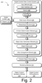
- FIG. 2 depicts a system 200 in an example implementation showing operation of the digital content view control system 116 of FIG. 1 in greater detail.
- FIG. 3 depicts an example 300 of a hierarchical structure of objects included as part of digital content 106.
- FIG. 4 depicts an example 400 shown using first and second stages 402, 404 in which an option 130 is selected in a user interface 110 that renders digital content 106 in a linear perspective (i.e., flat planar view) to cause output of a perspective view of objects included in the digital content 106.
- FIG. 5 depicts an example 500 of defining a direction for a multipoint perspective to be used to generate perspective object views of objects included as part of digital content 106.
- FIG. 1 depicts an example 300 of a hierarchical structure of objects included as part of digital content 106.
- FIG. 4 depicts an example 400 shown using first and second stages 402, 404 in which an option 130 is selected in a user interface 110 that renders digital content 106 in a linear perspective (i.e.,
- FIG. 6 depicts an example 600 illustrated using first and second stages 602, 604 in which interaction with perspective object views is used to reorder objects 118 in a z-ordering within the digital content 106.
- FIG. 7 depicts an example 700 illustrated using first and second stages 702, 704 of editing an object selected using a corresponding perspective object view.
- FIG. 8 depicts another example 800 illustrated using first and second stages 802, 804 of editing an object selected using a corresponding perspective object view.
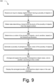
- FIG. 9 depicts a procedure 900 in an example implementation of digital content view control of objects.
- FIG. 10 depicts another example 1000 illustrated using first and second stages 1002, 1004 of a sensor that detects orientation of the computing device 102 to control output of different views of the objects 118 of the digital content 106.
- FIG. 11 depicts a procedure 1100 in an example implementation of detecting orientation of a housing of a computing device 102 using a sensor, and from this, controlling outputs of different views of the objects 118 of the digital content 106.
- an input 202 is received to display digital content having a plurality of objects in perspective (block 902).
- the input 202 may be originated by the input module 204 in a variety of ways.
- the input 202 is generated responsive to user selection of the option 130 in the user interface 110.
- an option 130 is output as part of a linear perspective (i.e., flat planar view) of objects 118 included as part of digital content 106 rendered in a user interface 110.
- Selection of the option 130 causes rendering of object views of the object 118 in a z-ordering as separated from each other as part of a multipoint perspective, an example of which is shown at a second stage 404 of FIG. 4 .
- the input 202 is originated by a sensor 206.
- the sensor 206 detects a change in orientation of the computing device 102, e.g., in three-dimensional space through detection of multi-axis movement. This change is used as a basis to switch from a linear perspective of the objects as shown at the first stage 402 to a multipoint perspective as shown at the second stage 404. Further discussion of the use of sensors to detect multiaxial movement is further described in relation to FIGS. 10 and 11 .
- Receipt of the input 202 by a data query module 208 causes the module to obtain data from the digital content 106 that describes a hierarchical structure 210 of the plurality of objects 118 (block 904) as defined within the digital content 106.
- An example of a digital content 106 having a hierarchical structure 302 defined using a markup language is depicted in FIG. 3 .
- the hierarchical structure 302 is formed using the markup language to control a structure of objects included in the content as they relate to each other.
- the hierarchical structure 302, for instance, includes tags that specify hierarchical containment and nesting structures to organize objects.
- a z-order determination module 212 is utilized to determine a z-order of the plurality of objects, one to another, based on the hierarchical structure (block 906) which is output as z-ordering data 214.
- the z-order determination module 212 maps the hierarchical containment and nesting structures described in the hierarchical structure 210 to nodes in a tree-like graphical structure. For the example of FIG. 3 , this creates a root node 304, a first child node 306 that is ordered from the root node 304, and a second child node 308 is ordered after the first child node 306.
- the background object 310 is mapped to the root node 304, a first foreground object 312 as a picnic table is mapped to a first child node 306, and a second foreground object 314 of a dog is mapped to a second child node 308. From this, the z-ordering of the objects as relating to each other is readily determined.
- An object view determination module 216 is also employed by the digital content view control system 116 to generate a plurality of object views 218 (e.g., perspective object views) of individual objects that are selectable via the user interface 110 (block 908).
- the object views 218 are configurable in a variety of ways to exhibit arrangement of the objects 118 according to the z-order.
- An example of this is perspective object views using multipoint perspective.
- Linear perspective is used to display the objects on a flat planar surface. To exhibit depth in linear perspective, a size of the objects is decreased as distance from an observer increases.
- Linear perspective includes a single vanishing point for an image plane, at which, parallel lines from a ground plane converge. Thus, in this example the observer is positioned at a point that is orthogonal to the image plane.
- Multipoint perspective includes two or more vanishing points. Multipoint perspective is usable to depict the same objects as in a linear perspective, but show those objects rotated as shown in FIG. 5.
- FIG. 5 includes a ground plane 502 having parallel lines that, when intersecting an image plane 504, converge at a vanishing point 506. As illustrated, an observer in this example views the image plane 504 "from the side.”
- examples or perspective object views 406, 408, 410 are depicted as rendered in the user interface 110 based on a multipoint (e.g., two point) perspective.
- Each of the perspective object views 408-410 employ first vanishing points that define depth "within” the objects, e.g., for a horizon of a park of the background object.
- the perspective object views 408-410 also employ a second vanishing point for the image plane of the objects along which the objects are positioned.
- this causes a right side of the object views to appear smaller and further away from the observer than a left side of the object views based on the second vanishing point, e.g., as exhibited by the top and bottom lines of the object views that while parallel appear to converge at this vanishing point.
- a view arrangement module 220 is then employed to generated ordered object views 222 by arranging and spacing the plurality of perspective object views, one to another, according to the z-order (block 910).
- the object views 218 are defined in relation to an angle, e.g., forty-five degrees with respect to a Y axis. This angle may be set as a default, specified via a user input (e.g., entered as an amount, through interaction with a control 412 depicted as a slider), and so on.
- the object views 218 are spaced, one to another, in the user interface 110. This is also performable based on a default amount, based on available spacing and number of views within the user interface 110, through interaction with the control 412 to increase or decrease spacing, and so forth.
- the ordered object views 222 are then rendered by a rendering module 224 for display in a user interface 110 by a display device 112 (block 912), e.g., as perspective object views.
- This rendering is performable in a variety of ways to support a corresponding variety of functionality.
- a digital content navigation module 226 is configured to support navigation to (i.e., selection of) particular objects using the perspective object views.
- a digital content editing module 228 is configured to support editing to individual objects using the perspective object views.
- FIG. 6 depicts an example using first and second stages 602, 604.
- the first, second, and third perspective objects 406, 408, 410 are rendered as discussed in relation to FIG. 4 .
- a user input is received via the user interface 110 that selects the third perspective object 410 to change its z-ordering to between the first and second perspective objects 408, 410.
- Another user input is selected via the option 130 to toggle between the multipoint perspective view of the first stage 602 to a linear perspective view of the second stage 604, which may be repeated to return to the linear perspective view. As illustrated, this causes the dog to appear behind the picnic table in the digital content. Further, the option 130 supports an efficient technique to select a particular object view from the multipoint perspective view without the "cycling" involved in conventional techniques.
- the digital content editing module 228 is configured to support editing of the objects through interaction with the perspective object views. Rearrangement of the objects in the z-ordering above causes the dog to appear behind the picnic table as shown at the second stage 404 of FIG. 4 . Accordingly, in this example the third perspective view 410 is selected at the first stage 702 of FIG. 7 to enter into an editing view.
- the second stage 704 includes an example of the editing view having a content view portion 706, a perspective view portion 708, and an editing portion 710.
- the editing portion 710 is configured to display objects corresponding to the perspective view portion selected at the first stage 702. Edits are then made to this portion without directly affecting other objects in the digital content 106, e.g., such as to resize and reposition the dog.
- An effect of those edits made to the editing portion 710 are also made to the digital content 106 in real time as these edits are received.
- the editing view supports selection of particular perspective object views via the perspective view portion 708, which are output in the editing portion 710 for editing.
- An indication 712 is also provided via the user interface by changing a display characteristic of the perspective object views to indicate which view is currently selected for editing.
- FIG. 8 depicts another example of an editing view.
- the first stage 802 includes the first, second, and third perspective views 406, 408, 410 arranged as described in relation to the second stage 404 of FIG. 4 .
- the third perspective view 410 is again selected for editing.
- a stack arrangement editing view is entered.
- Selection of the third selected perspective view 410 causes the corresponding digital object 806 of the dog to be output in the user interface 110 in a linear perspective.
- the first and second perspective views 406, 408 are also included in the user interface 110, and are selectable to navigate to corresponding objects for editing.
- This editing view is also configurable to support additional portions, such as the content view portion 706 of FIG. 7 to depict an effect of the edits on the digital content 106 as a whole in real time as those edits are received.
- user inputs received via the user interface 110 are used to control output of the perspective object views.
- Other examples are also contemplated, including use of sensors which are described as follows.
- FIG. 10 depicts an example implementation in which detection of a change in orientation of a computing device 102 in three-dimensional space is utilized to control switching between a linear perspective and a multipoint perspective view of objects in digital content.
- the computing device 102 in this example includes an orientation determination module 1008 having sensors 206 that are configured to generate orientation data 1010 responsive to detecting an orientation and/or a change in orientation of the computing device 102 in three-dimensional space.
- the computing device 102 is illustrated in this example as having a portable form factor that includes a housing 1006, on which, the display device 112 is disposed.
- the sensors 206 are configurable as an accelerometer, passive infrared sensor, gyroscope, digital camera, ultrasonic sensor, microwave sensor, tomographic sensor, or any other type of sensor that is configured to detect a multiaxis orientation or a change in multiaxis orientation of the computing device 102.
- the sensors 206 as disposed within the housing 1006, are configured to detect orientation and/or changes in orientation. This orientation is inferred to occur with respect to the housing 1006 and corresponding display device 112, and as such, an orientation determination module 1008 is configured to determine "how" the digital content is viewed via the user interface 110.
- the digital content view control system 116 is configured to toggle between a linear perspective as illustrated as the first stage 1002 and a multipoint perspective as illustrated at the second stage 1004.
- the digital content view control system 116 detects a first orientation of the housing 1006 as disposed in three-dimensional space using the sensor 206 (block 1102).
- This first orientation for instance, is configured such that a viewpoint of the computing device 102 (and more particularly the display device 112) is disposed orthogonal to a surface of the display device 112. Accordingly, the user interface 110 is displayed as having a plurality of objects included as part of the digital content in a linear perspective view (block 1104).
- the housing 1006 of the computing device 102 is moved to a second orientation.
- the second orientation of the housing 1006 as disposed in three-dimensional space is detected using the sensor 206 (block 1106).
- the user interface 110 is then configured by the digital content view control system 116 to have the plurality of objects displayed in multipoint perspective view (block 1108).
- multipoint perspective views of the objects are generated as described above. These views are also spaced apart from each other to indicate a z-ordering. For example, the text "Lucy Dog Treats!" and the "Buy Now” button are arranged in a first layer, the dog is arranged in a second layer, and the tree is arranged in a third layer.
- These views are configured such that the different objects appear to "float" above the screen. In one example, this is performed through use of a multipoint perspective of the views that differs from a perspective, at which, the display device 112 and user interface 110 appear to the user. In other words, a vanishing point used to define an image plane for the views differs from a vanishing point of the device, itself. In this way, movement of the computing device 102 as a whole is used to efficiently toggle between these views and addresses the challenges of a small form factor employed by portable devices.
- FIG. 12 illustrates an example system generally at 1200 that includes an example computing device 1202 that is representative of one or more computing systems and/or devices that implement the various techniques described herein. This is illustrated through inclusion of the digital content view control system 116.
- the computing device 1202 is configurable, for example, as a server of a service provider, a device associated with a client (e.g., a client device), an on-chip system, and/or any other suitable computing device or computing system.
- the example computing device 1202 as illustrated includes a processing system 1204, one or more computer-readable media 1206, and one or more I/O interface 1208 that are communicatively coupled, one to another.
- the computing device 1202 further includes a system bus or other data and command transfer system that couples the various components, one to another.
- a system bus can include any one or combination of different bus structures, such as a memory bus or memory controller, a peripheral bus, a universal serial bus, and/or a processor or local bus that utilizes any of a variety of bus architectures.
- a variety of other examples are also contemplated, such as control and data lines.
- the processing system 1204 is representative of functionality to perform one or more operations using hardware. Accordingly, the processing system 1204 is illustrated as including hardware element 1210 that is configurable as processors, functional blocks, and so forth. This includes implementation in hardware as an application specific integrated circuit or other logic device formed using one or more semiconductors.
- the hardware elements 1210 are not limited by the materials from which they are formed or the processing mechanisms employed therein.
- processors are configurable as semiconductor(s) and/or transistors (e.g., electronic integrated circuits (ICs)).
- processor-executable instructions are electronically-executable instructions.
- the computer-readable storage media 1206 is illustrated as including memory/storage 1212.
- the memory/storage 1212 represents memory/storage capacity associated with one or more computer-readable media.
- the memory/storage 1212 includes volatile media (such as random access memory (RAM)) and/or nonvolatile media (such as read only memory (ROM), Flash memory, optical disks, magnetic disks, and so forth).
- the memory/storage 1212 includes fixed media (e.g., RAM, ROM, a fixed hard drive, and so on) as well as removable media (e.g., Flash memory, a removable hard drive, an optical disc, and so forth).
- the computer-readable media 1206 is configurable in a variety of other ways as further described below.
- Input/output interface(s) 1208 are representative of functionality to allow a user to enter commands and information to computing device 1202, and also allow information to be presented to the user and/or other components or devices using various input/output devices.
- input devices include a keyboard, a cursor control device (e.g., a mouse), a microphone, a scanner, touch functionality (e.g., capacitive or other sensors that are configured to detect physical touch), a camera (e.g., employing visible or non-visible wavelengths such as infrared frequencies to recognize movement as gestures that do not involve touch), and so forth.
- Examples of output devices include a display device (e.g., a monitor or projector), speakers, a printer, a network card, tactile-response device, and so forth.
- a display device e.g., a monitor or projector
- speakers e.g., speakers
- a printer e.g., a printer
- network card e.g., a network card
- tactile-response device e.g., a printer, a printer, a network card, tactile-response device, and so forth.
- the computing device 1202 is configurable in a variety of ways as further described below to support user interaction.
- modules include routines, programs, objects, elements, components, data structures, and so forth that perform particular tasks or implement particular abstract data types.
- module generally represent software, firmware, hardware, or a combination thereof.
- the features of the techniques described herein are platform-independent, meaning that the techniques are configurable on a variety of commercial computing platforms having a variety of processors.
- Computer-readable media includes a variety of media that is accessed by the computing device 1202.
- computer-readable media includes “computer-readable storage media” and “computer-readable signal media.”
- Computer-readable storage media refers to media and/or devices that enable persistent and/or non-transitory storage of information in contrast to mere signal transmission, carrier waves, or signals per se. Thus, computer-readable storage media refers to non-signal bearing media.
- the computer-readable storage media includes hardware such as volatile and non-volatile, removable and non-removable media and/or storage devices implemented in a method or technology suitable for storage of information such as computer readable instructions, data structures, program modules, logic elements/circuits, or other data.
- Examples of computer-readable storage media include but are not limited to RAM, ROM, EEPROM, flash memory or other memory technology, CD-ROM, digital versatile disks (DVD) or other optical storage, hard disks, magnetic cassettes, magnetic tape, magnetic disk storage or other magnetic storage devices, or other storage device, tangible media, or article of manufacture suitable to store the desired information and are accessible by a computer.
- Computer-readable signal media refers to a signal-bearing medium that is configured to transmit instructions to the hardware of the computing device 1202, such as via a network.
- Signal media typically embodies computer readable instructions, data structures, program modules, or other data in a modulated data signal, such as carrier waves, data signals, or other transport mechanism.
- Signal media also include any information delivery media.
- modulated data signal means a signal that has one or more of its characteristics set or changed in such a manner as to encode information in the signal.
- communication media include wired media such as a wired network or direct-wired connection, and wireless media such as acoustic, RF, infrared, and other wireless media.
- hardware elements 1210 and computer-readable media 1206 are representative of modules, programmable device logic and/or fixed device logic implemented in a hardware form that are employed in some embodiments to implement at least some aspects of the techniques described herein, such as to perform one or more instructions.
- Hardware includes components of an integrated circuit or on-chip system, an application-specific integrated circuit (ASIC), a field-programmable gate array (FPGA), a complex programmable logic device (CPLD), and other implementations in silicon or other hardware.
- ASIC application-specific integrated circuit
- FPGA field-programmable gate array
- CPLD complex programmable logic device
- hardware operates as a processing device that performs program tasks defined by instructions and/or logic embodied by the hardware as well as a hardware utilized to store instructions for execution, e.g., the computer-readable storage media described previously.
- software, hardware, or executable modules are implemented as one or more instructions and/or logic embodied on some form of computer-readable storage media and/or by one or more hardware elements 1210.
- the computing device 1202 is configured to implement particular instructions and/or functions corresponding to the software and/or hardware modules. Accordingly, implementation of a module that is executable by the computing device 1202 as software is achieved at least partially in hardware, e.g., through use of computer-readable storage media and/or hardware elements 1210 of the processing system 1204.
- the instructions and/or functions are executable/operable by one or more articles of manufacture (for example, one or more computing devices 1202 and/or processing systems 1204) to implement techniques, modules, and examples described herein.
- the techniques described herein are supported by various configurations of the computing device 1202 and are not limited to the specific examples of the techniques described herein. This functionality is also implementable all or in part through use of a distributed system, such as over a "cloud" 1214 via a platform 1216 as described below.
- the cloud 1214 includes and/or is representative of a platform 1216 for resources 1218.
- the platform 1216 abstracts underlying functionality of hardware (e.g., servers) and software resources of the cloud 1214.
- the resources 1218 include applications and/or data that can be utilized while computer processing is executed on servers that are remote from the computing device 1202.
- Resources 1218 can also include services provided over the Internet and/or through a subscriber network, such as a cellular or Wi-Fi network.
- the platform 1216 abstracts resources and functions to connect the computing device 1202 with other computing devices.
- the platform 1216 also serves to abstract scaling of resources to provide a corresponding level of scale to encountered demand for the resources 1218 that are implemented via the platform 1216. Accordingly, in an interconnected device embodiment, implementation of functionality described herein is distributable throughout the system 1200. For example, the functionality is implementable in part on the computing device 1202 as well as via the platform 1216 that abstracts the functionality of the cloud 1214.
Landscapes
- Engineering & Computer Science (AREA)
- Theoretical Computer Science (AREA)
- General Engineering & Computer Science (AREA)
- Physics & Mathematics (AREA)
- General Physics & Mathematics (AREA)
- Human Computer Interaction (AREA)
- Computer Graphics (AREA)
- Computer Hardware Design (AREA)
- Computing Systems (AREA)
- Geometry (AREA)
- Architecture (AREA)
- Software Systems (AREA)
- User Interface Of Digital Computer (AREA)
- Processing Or Creating Images (AREA)
Abstract
Description
- Digital content is configurable to include a multitude of objects as part of digital images, design of a user interface, webpages, digital multimedia, digital documents, and so forth. Oftentimes, this multitude of objects include overlaps, are nested within each other, and so forth. As such, this presents a challenge to conventional techniques that are supported by computing devices to select and interact with individual objects within the digital content.
- Consider an example of a collection of objects that are visually nested and layered within each other, e.g., to depict collections of device components in a user interface such as semiconductor chips on a circuit board within a housing. In order to select a particular one of these objects in the user interface using conventional techniques, a series of user inputs are provided at a same location in the user interface to select a particular object. This causes the computing device to "cycle through" different objects until an object of interest is indicated as selected. Any mistake in this series of selections, however, forces the user to "start over" and repeat through the cycle to achieve a desired selection. This challenge is further exacerbated when zooming to a particular object such that other objects that are nested as part of the collection are not directly viewable in the user interface. This results in user frustration and inefficient use of computational resources caused by these repeated selections.
- Digital content view control is described as leveraging a hierarchical structure of objects defined within the digital content to control how those objects are rendered in a user interface. In one example, a user input is received to display a view of objects within digital content displayed in a user interface. In response, a data query module is configured to fetch data describing a hierarchical structure of the digital content. From this, a z-order determination module determines a z-order of objects included with the digital content, e.g., by examining a hierarchy defined by tags within the markup language. An object view generation module is also configured to generate object views depicting the objects included in the digital content. The object views, once rendered, support an ability to view positioning of objects within the hierarchy, e.g., to indicate overlaps, nesting, and so forth.
- This Summary introduces a selection of concepts in a simplified form that are further described below in the Detailed Description. As such, this Summary is not intended to identify essential features of the claimed subject matter, nor is it intended to be used as an aid in determining the scope of the claimed subject matter.
- The detailed description is described with reference to the accompanying figures. Entities represented in the figures are indicative of one or more entities and thus reference is made interchangeably to single or plural forms of the entities in the discussion.
-
FIG. 1 is an illustration of an environment in an example implementation that is operable to employ digital content view control techniques described herein. -
FIG. 2 depicts a system in an example implementation showing operation of a digital content view control system ofFIG. 1 in greater detail. -
FIG. 3 depicts an example of a hierarchical structure of objects included as part of digital content. -
FIG. 4 depicts an example shown using first and second stages in which an option is selected in a user interface that renders digital content in a linear perspective (i.e., flat planar view) to cause output of a multipoint perspective view of objects included in the digital content. -
FIG. 5 depicts an example of defining a direction as part of a multipoint perspective to be used to generate perspective object views of objects included as part of digital content. -
FIG. 6 depicts an example illustrated using first and second stages in which interaction with perspective object views is used to reorder objects in a z-ordering within the digital content. -
FIG. 7 depicts an example illustrated using first and second stages of editing an object selected using a corresponding perspective object view. -
FIG. 8 depicts another example illustrated using first and second stages of editing an object selected using a corresponding perspective object view. -
FIG. 9 is a flow diagram depicting a procedure in an example implementation of digital content view control of objects. -
FIG. 10 depicts another example illustrated using first and second stages of use of sensor that detects orientation of the computing device to control output of different views of the objects of the digital content. -
FIG. 11 is a flow diagram depicting a procedure in an example implementation of detecting orientation of a housing of a computing device using a sensor, and from this, controlling output of different views of the objects of the digital content. -
FIG. 12 illustrates an example system including various components of an example device that can be implemented as any type of computing device as described and/or utilize with reference toFIGS. 1-11 to implement embodiments of the techniques described herein. - The complexity of digital content and corresponding uses for that content are ever increasing. Consider an example of evolution of digital content configured as a webpage. Initially, webpages included a simple body of text and maybe a title. As webpages evolve, a multitude of graphics, art, buttons, portions that support streaming, and so on are included in everyday examples. Consequently, however, creation, editing, and interaction with this digital content is further complicated by overlaps, nesting, and arrangement of objects used to form the digital content. This results in user frustration and inefficient use of computational resources as part of editing and interacting with this digital content.
- Accordingly, digital content view control techniques and systems are described to control how objects within digital objects are viewed to support navigation, editing, and arrangement of the objects. This results in increased efficiency in user interaction and computational resource consumption. Continuing the webpage example above, consider an example in which the webpage includes multiple objects that overlap, are nested within each other (e.g., a boundary of a first object is included within a boundary of a second object), and so on. Conventional techniques used to select a particular object typically involved repeated selection (e.g., at a single location within the user interface) to cycle through the different objects overlapping the location until a desired object is indicated as selected. This conventional technique is thus inefficient, prone to error, and results in user frustration.
- In the following, however, a digital content view control system is configured to leverage a hierarchical structure of objects defined within the digital content to control how those objects are rendered in a user interface. For the webpage example, a markup language (e.g., HTML) is used to define what different objects "are" in the digital content as well as presentation semantics describe how to present the objects of the digital content. As part of this, the markup language defines a hierarchical structure of objects in relation to each other within the digital content, e.g., through the use of tags. The digital content view system is configured to examine this structure to determine a z-order arrangement of objects that is used as a basis to represent the objects as spaced within a user interface, e.g., as an exploded view. An exploded view, for instance, depicts a relationship and order of objects based on the relationship and order of the objects from the digital content as separated by a distance.
- In one example, a user input is received to display a view of objects within digital content displayed in a user interface. The user input is received responsive to selection of an option in the user interface to switch from a flat planar view (e.g., a linear perspective) in which the objects are displayed as overlapping in a single plane in the user interface to a multipoint perspective view of the objects.
- In response, a data query module is configured to fetch data describing a hierarchical structure of the digital content, e.g., a markup language. From this, a z-order determination module determines a z-order of objects included with the digital content, e.g., by examining a hierarchy defined by tags within the markup language.
- An object view generation module is also configured to generate object views depicting the objects included in the digital content. In one example, the object views are perspective object views based on a multipoint perspective. An object view generation module, for instance, determines a direction of a perspective for a multipoint perspective defining a plane between a viewpoint and a vanishing point. The direction may be specified in a variety of ways, such as via a user input, predefined (e.g., forty-five degrees on a Y axis), and so forth. The objects are then distorted to follow this plane and are spaced apart in the user interface. The spacing is also definable in a variety of ways, such as predefined amount, user specified amount (e.g., via a control such as a slider), and so forth.
- The object views, once rendered, support an ability to view positioning of objects within the hierarchy, e.g., to indicate overlaps, nesting, and so forth. The objects views support a variety of functionality, examples of which include navigation directly to a corresponding object (thereby avoiding conventional cyclic selection techniques), editing of the objects, rearrangement of the objects in the hierarchy which is then propagated "back" to also edit the markup language, and so forth. As a result, the digital content view control techniques and systems described herein overcome challenges of conventional techniques with increased user and computational efficiency. Further discussion of these and other examples is included in the following sections and shown in corresponding figures.
- In the following discussion, an example environment is described that employs the techniques described herein. Example procedures are also described that are performable in the example environment as well as other environments. Consequently, performance of the example procedures is not limited to the example environment and the example environment is not limited to performance of the example procedures.
-
FIG. 1 is an illustration of anenvironment 100 in an example implementation that is operable to employ digital content view control techniques described herein. The illustratedenvironment 100 includes acomputing device 102, which is configurable in a variety of ways. - The
computing device 102, for instance, is configurable as a desktop computer, a laptop computer, a mobile device (e.g., assuming a handheld configuration such as a tablet or mobile phone), and so forth. Thus, thecomputing device 102 ranges from full resource devices with substantial memory and processor resources (e.g., personal computers, game consoles) to a low-resource device with limited memory and/or processing resources (e.g., mobile devices). Additionally, although asingle computing device 102 is shown, thecomputing device 102 is also representative of a plurality of different devices, such as multiple servers utilized by a business to perform operations "over the cloud" as described inFIG. 12 . - The
computing device 102 is illustrated as including acontent processing system 104. Thecontent processing system 104 is implemented at least partially in hardware of thecomputing device 102 to process and transformdigital content 106, which is illustrated as maintained instorage 108 of thecomputing device 102. Such processing includes creation of thedigital content 106, modification of thedigital content 106, and rendering of thedigital content 106 in auser interface 110 for output, e.g., by adisplay device 112. Although illustrated as implemented locally at thecomputing device 102, functionality of thecontent processing system 104 is also configurable as whole or part via functionality available via thenetwork 114, such as part of a web service or "in the cloud." Examples ofdigital content 106 include digital images, digital media, webpages, digital documents, and any other form of content that is configured for rendering and display by thedisplay device 112 in theuser interface 110. - An example of functionality incorporated by the
image processing system 104 to process thedigital content 106 is illustrated as a digital contentview control system 116. This system is configured to control interaction withobjects 118 included as part of thedigital content 106. Examples ofobjects 118 include vector objects, raster objects, text, digital images, representations of executable functionality that is selectable via the representations (e.g., buttons, controls, sliders, radial dials, media controls), and so forth. - As a number of
objects 118 included in thedigital content 106 increases, so too does the complexity of editing and interacting with theseobjects 118. In a first such example, a collection of overlapping first, second, andthird objects first object 120 partially overlaps thesecond object 122. The first andsecond objects third object 124. This reflects a z-ordering outward fromthird object 124 to thesecond object 122 to thefirst object 120. Selection of individual objects is complicated by this overlap. A cursor, for instance, is illustrated as disposed at asingle location 126 in theuser interface 110. Conventional techniques to select any one of the first, second, andthird objects user interface 110 of a desired selection, which is prone to error. This challenge is further complicated by complexdigital content 106, such as thedigital image 128 of a park scene with a picnic table and dog catching a ball. It is difficult in this situation, for instance, to determine which objects are selectable separately (e.g., is the dog, picnic bench, lamp post or tree selectable?), select particular objects, accurately determine a correct z-ordering of the objects, and so forth. - Accordingly, the digital content
view control system 116 includes anoption 130 that is user selectable to initiate a view of theobjects 118, separately, that is indicative of a z-ordering of the objects as well as which object are included together and/or disposed separately in theuser interface 110. Other examples are also contemplated that do not involve selection of theoption 130, e.g., for sensor-based techniques as described in relation toFIGS. 10 and11 . - In general, functionality, features, and concepts described in relation to the examples above and below are employed in the context of the example procedures described in this section. Further, functionality, features, and concepts described in relation to different figures and examples in this document are interchangeable among one another and are not limited to implementation in the context of a particular figure or procedure. Moreover, blocks associated with different representative procedures and corresponding figures herein are applicable together and/or combinable in different ways. Thus, individual functionality, features, and concepts described in relation to different example environments, devices, components, figures, and procedures herein are usable in any suitable combinations and are not limited to the particular combinations represented by the enumerated examples in this description.
-
FIG. 2 depicts asystem 200 in an example implementation showing operation of the digital contentview control system 116 ofFIG. 1 in greater detail.FIG. 3 depicts an example 300 of a hierarchical structure of objects included as part ofdigital content 106.FIG. 4 depicts an example 400 shown using first andsecond stages option 130 is selected in auser interface 110 that rendersdigital content 106 in a linear perspective (i.e., flat planar view) to cause output of a perspective view of objects included in thedigital content 106.FIG. 5 depicts an example 500 of defining a direction for a multipoint perspective to be used to generate perspective object views of objects included as part ofdigital content 106.FIG. 6 depicts an example 600 illustrated using first andsecond stages objects 118 in a z-ordering within thedigital content 106.FIG. 7 depicts an example 700 illustrated using first andsecond stages FIG. 8 depicts another example 800 illustrated using first andsecond stages FIG. 9 depicts aprocedure 900 in an example implementation of digital content view control of objects.FIG. 10 depicts another example 1000 illustrated using first andsecond stages computing device 102 to control output of different views of theobjects 118 of thedigital content 106.FIG. 11 depicts aprocedure 1100 in an example implementation of detecting orientation of a housing of acomputing device 102 using a sensor, and from this, controlling outputs of different views of theobjects 118 of thedigital content 106. - The following discussion describes techniques that are implementable utilizing the previously described systems and devices. Aspects of each of the procedures are implemented in hardware, firmware, software, or a combination thereof. The procedures are shown as a set of blocks that specify operations performed by one or more devices and are not necessarily limited to the orders shown for performing the operations by the respective blocks. In portions of the following discussion, reference will be made to
FIGS. 1-11 . - To begin, an
input 202 is received to display digital content having a plurality of objects in perspective (block 902). Theinput 202 may be originated by theinput module 204 in a variety of ways. In a first example, theinput 202 is generated responsive to user selection of theoption 130 in theuser interface 110. As shown at afirst stage 402 ofFIG. 4 , anoption 130 is output as part of a linear perspective (i.e., flat planar view) ofobjects 118 included as part ofdigital content 106 rendered in auser interface 110. Selection of theoption 130 causes rendering of object views of theobject 118 in a z-ordering as separated from each other as part of a multipoint perspective, an example of which is shown at asecond stage 404 ofFIG. 4 . - In another example, the
input 202 is originated by asensor 206. Thesensor 206, for instance, detects a change in orientation of thecomputing device 102, e.g., in three-dimensional space through detection of multi-axis movement. This change is used as a basis to switch from a linear perspective of the objects as shown at thefirst stage 402 to a multipoint perspective as shown at thesecond stage 404. Further discussion of the use of sensors to detect multiaxial movement is further described in relation toFIGS. 10 and11 . - Receipt of the
input 202 by adata query module 208 causes the module to obtain data from thedigital content 106 that describes ahierarchical structure 210 of the plurality of objects 118 (block 904) as defined within thedigital content 106. An example of adigital content 106 having ahierarchical structure 302 defined using a markup language is depicted inFIG. 3 . Thehierarchical structure 302 is formed using the markup language to control a structure of objects included in the content as they relate to each other. Thehierarchical structure 302, for instance, includes tags that specify hierarchical containment and nesting structures to organize objects. - In this example, once the data describing the
hierarchical structure 210 is obtained, a z-order determination module 212 is utilized to determine a z-order of the plurality of objects, one to another, based on the hierarchical structure (block 906) which is output as z-orderingdata 214. The z-order determination module 212, for instance, maps the hierarchical containment and nesting structures described in thehierarchical structure 210 to nodes in a tree-like graphical structure. For the example ofFIG. 3 , this creates a root node 304, afirst child node 306 that is ordered from the root node 304, and asecond child node 308 is ordered after thefirst child node 306. Thebackground object 310 is mapped to the root node 304, afirst foreground object 312 as a picnic table is mapped to afirst child node 306, and a second foreground object 314 of a dog is mapped to asecond child node 308. From this, the z-ordering of the objects as relating to each other is readily determined. - An object
view determination module 216 is also employed by the digital contentview control system 116 to generate a plurality of object views 218 (e.g., perspective object views) of individual objects that are selectable via the user interface 110 (block 908). The object views 218 are configurable in a variety of ways to exhibit arrangement of theobjects 118 according to the z-order. An example of this is perspective object views using multipoint perspective. Linear perspective is used to display the objects on a flat planar surface. To exhibit depth in linear perspective, a size of the objects is decreased as distance from an observer increases. Linear perspective includes a single vanishing point for an image plane, at which, parallel lines from a ground plane converge. Thus, in this example the observer is positioned at a point that is orthogonal to the image plane. - Multipoint perspective includes two or more vanishing points. Multipoint perspective is usable to depict the same objects as in a linear perspective, but show those objects rotated as shown in
FIG. 5. FIG. 5 includes a ground plane 502 having parallel lines that, when intersecting animage plane 504, converge at a vanishing point 506. As illustrated, an observer in this example views theimage plane 504 "from the side." - At the
second stage 404 ofFIG. 4 , examples or perspective object views 406, 408, 410 are depicted as rendered in theuser interface 110 based on a multipoint (e.g., two point) perspective. Each of the perspective object views 408-410 employ first vanishing points that define depth "within" the objects, e.g., for a horizon of a park of the background object. The perspective object views 408-410 also employ a second vanishing point for the image plane of the objects along which the objects are positioned. As illustrated, this causes a right side of the object views to appear smaller and further away from the observer than a left side of the object views based on the second vanishing point, e.g., as exhibited by the top and bottom lines of the object views that while parallel appear to converge at this vanishing point. - A
view arrangement module 220 is then employed to generated ordered object views 222 by arranging and spacing the plurality of perspective object views, one to another, according to the z-order (block 910). Continuing with the example above, the object views 218 are defined in relation to an angle, e.g., forty-five degrees with respect to a Y axis. This angle may be set as a default, specified via a user input (e.g., entered as an amount, through interaction with acontrol 412 depicted as a slider), and so on. Further, the object views 218 are spaced, one to another, in theuser interface 110. This is also performable based on a default amount, based on available spacing and number of views within theuser interface 110, through interaction with thecontrol 412 to increase or decrease spacing, and so forth. - The ordered object views 222 are then rendered by a
rendering module 224 for display in auser interface 110 by a display device 112 (block 912), e.g., as perspective object views. This rendering is performable in a variety of ways to support a corresponding variety of functionality. For example, a digitalcontent navigation module 226 is configured to support navigation to (i.e., selection of) particular objects using the perspective object views. In another example, a digitalcontent editing module 228 is configured to support editing to individual objects using the perspective object views. -
FIG. 6 , for instance, depicts an example using first andsecond stages first stage 602, the first, second, and third perspective objects 406, 408, 410 are rendered as discussed in relation toFIG. 4 . A user input is received via theuser interface 110 that selects thethird perspective object 410 to change its z-ordering to between the first and second perspective objects 408, 410. - Another user input is selected via the
option 130 to toggle between the multipoint perspective view of thefirst stage 602 to a linear perspective view of thesecond stage 604, which may be repeated to return to the linear perspective view. As illustrated, this causes the dog to appear behind the picnic table in the digital content. Further, theoption 130 supports an efficient technique to select a particular object view from the multipoint perspective view without the "cycling" involved in conventional techniques. - Continuing the example above the digital
content editing module 228 is configured to support editing of the objects through interaction with the perspective object views. Rearrangement of the objects in the z-ordering above causes the dog to appear behind the picnic table as shown at thesecond stage 404 ofFIG. 4 . Accordingly, in this example thethird perspective view 410 is selected at thefirst stage 702 ofFIG. 7 to enter into an editing view. - The
second stage 704 includes an example of the editing view having acontent view portion 706, aperspective view portion 708, and anediting portion 710. Theediting portion 710 is configured to display objects corresponding to the perspective view portion selected at thefirst stage 702. Edits are then made to this portion without directly affecting other objects in thedigital content 106, e.g., such as to resize and reposition the dog. - An effect of those edits made to the
editing portion 710 are also made to thedigital content 106 in real time as these edits are received. In this way, the editing view supports selection of particular perspective object views via theperspective view portion 708, which are output in theediting portion 710 for editing. Anindication 712 is also provided via the user interface by changing a display characteristic of the perspective object views to indicate which view is currently selected for editing. -
FIG. 8 depicts another example of an editing view. In this example, thefirst stage 802 includes the first, second, and third perspective views 406, 408, 410 arranged as described in relation to thesecond stage 404 ofFIG. 4 . Thethird perspective view 410 is again selected for editing. - In this example, however, as shown at the second stage 410 a stack arrangement editing view is entered. Selection of the third selected
perspective view 410, for instance, causes the correspondingdigital object 806 of the dog to be output in theuser interface 110 in a linear perspective. The first and second perspective views 406, 408 are also included in theuser interface 110, and are selectable to navigate to corresponding objects for editing. Thus, in this example positioning within the z-order is illustrated while still supporting edits to individual objects. This editing view is also configurable to support additional portions, such as thecontent view portion 706 ofFIG. 7 to depict an effect of the edits on thedigital content 106 as a whole in real time as those edits are received. In these examples, user inputs received via theuser interface 110 are used to control output of the perspective object views. Other examples are also contemplated, including use of sensors which are described as follows. -
FIG. 10 depicts an example implementation in which detection of a change in orientation of acomputing device 102 in three-dimensional space is utilized to control switching between a linear perspective and a multipoint perspective view of objects in digital content. Thecomputing device 102 in this example includes an orientation determination module 1008 havingsensors 206 that are configured to generateorientation data 1010 responsive to detecting an orientation and/or a change in orientation of thecomputing device 102 in three-dimensional space. - The
computing device 102 is illustrated in this example as having a portable form factor that includes ahousing 1006, on which, thedisplay device 112 is disposed. Thesensors 206, for instance, are configurable as an accelerometer, passive infrared sensor, gyroscope, digital camera, ultrasonic sensor, microwave sensor, tomographic sensor, or any other type of sensor that is configured to detect a multiaxis orientation or a change in multiaxis orientation of thecomputing device 102. Thesensors 206, as disposed within thehousing 1006, are configured to detect orientation and/or changes in orientation. This orientation is inferred to occur with respect to thehousing 1006 andcorresponding display device 112, and as such, an orientation determination module 1008 is configured to determine "how" the digital content is viewed via theuser interface 110. - Through use of this data, the digital content
view control system 116 is configured to toggle between a linear perspective as illustrated as thefirst stage 1002 and a multipoint perspective as illustrated at thesecond stage 1004. At thefirst stage 1002, for instance, the digital contentview control system 116 detects a first orientation of thehousing 1006 as disposed in three-dimensional space using the sensor 206 (block 1102). This first orientation, for instance, is configured such that a viewpoint of the computing device 102 (and more particularly the display device 112) is disposed orthogonal to a surface of thedisplay device 112. Accordingly, theuser interface 110 is displayed as having a plurality of objects included as part of the digital content in a linear perspective view (block 1104). - At the
second stage 1004, thehousing 1006 of thecomputing device 102 is moved to a second orientation. In response, the second orientation of thehousing 1006 as disposed in three-dimensional space is detected using the sensor 206 (block 1106). Theuser interface 110 is then configured by the digital contentview control system 116 to have the plurality of objects displayed in multipoint perspective view (block 1108). In this example, multipoint perspective views of the objects are generated as described above. These views are also spaced apart from each other to indicate a z-ordering. For example, the text "Lucy Dog Treats!!" and the "Buy Now" button are arranged in a first layer, the dog is arranged in a second layer, and the tree is arranged in a third layer. - These views are configured such that the different objects appear to "float" above the screen. In one example, this is performed through use of a multipoint perspective of the views that differs from a perspective, at which, the
display device 112 anduser interface 110 appear to the user. In other words, a vanishing point used to define an image plane for the views differs from a vanishing point of the device, itself. In this way, movement of thecomputing device 102 as a whole is used to efficiently toggle between these views and addresses the challenges of a small form factor employed by portable devices. -
FIG. 12 illustrates an example system generally at 1200 that includes anexample computing device 1202 that is representative of one or more computing systems and/or devices that implement the various techniques described herein. This is illustrated through inclusion of the digital contentview control system 116. Thecomputing device 1202 is configurable, for example, as a server of a service provider, a device associated with a client (e.g., a client device), an on-chip system, and/or any other suitable computing device or computing system. - The
example computing device 1202 as illustrated includes aprocessing system 1204, one or more computer-readable media 1206, and one or more I/O interface 1208 that are communicatively coupled, one to another. Although not shown, thecomputing device 1202 further includes a system bus or other data and command transfer system that couples the various components, one to another. A system bus can include any one or combination of different bus structures, such as a memory bus or memory controller, a peripheral bus, a universal serial bus, and/or a processor or local bus that utilizes any of a variety of bus architectures. A variety of other examples are also contemplated, such as control and data lines. - The
processing system 1204 is representative of functionality to perform one or more operations using hardware. Accordingly, theprocessing system 1204 is illustrated as includinghardware element 1210 that is configurable as processors, functional blocks, and so forth. This includes implementation in hardware as an application specific integrated circuit or other logic device formed using one or more semiconductors. Thehardware elements 1210 are not limited by the materials from which they are formed or the processing mechanisms employed therein. For example, processors are configurable as semiconductor(s) and/or transistors (e.g., electronic integrated circuits (ICs)). In such a context, processor-executable instructions are electronically-executable instructions. - The computer-
readable storage media 1206 is illustrated as including memory/storage 1212. The memory/storage 1212 represents memory/storage capacity associated with one or more computer-readable media. The memory/storage 1212 includes volatile media (such as random access memory (RAM)) and/or nonvolatile media (such as read only memory (ROM), Flash memory, optical disks, magnetic disks, and so forth). The memory/storage 1212 includes fixed media (e.g., RAM, ROM, a fixed hard drive, and so on) as well as removable media (e.g., Flash memory, a removable hard drive, an optical disc, and so forth). The computer-readable media 1206 is configurable in a variety of other ways as further described below. - Input/output interface(s) 1208 are representative of functionality to allow a user to enter commands and information to
computing device 1202, and also allow information to be presented to the user and/or other components or devices using various input/output devices. Examples of input devices include a keyboard, a cursor control device (e.g., a mouse), a microphone, a scanner, touch functionality (e.g., capacitive or other sensors that are configured to detect physical touch), a camera (e.g., employing visible or non-visible wavelengths such as infrared frequencies to recognize movement as gestures that do not involve touch), and so forth. Examples of output devices include a display device (e.g., a monitor or projector), speakers, a printer, a network card, tactile-response device, and so forth. Thus, thecomputing device 1202 is configurable in a variety of ways as further described below to support user interaction. - Various techniques are described herein in the general context of software, hardware elements, or program modules. Generally, such modules include routines, programs, objects, elements, components, data structures, and so forth that perform particular tasks or implement particular abstract data types. The terms "module," "functionality," and "component" as used herein generally represent software, firmware, hardware, or a combination thereof. The features of the techniques described herein are platform-independent, meaning that the techniques are configurable on a variety of commercial computing platforms having a variety of processors.
- An implementation of the described modules and techniques is stored on or transmitted across some form of computer-readable media. The computer-readable media includes a variety of media that is accessed by the
computing device 1202. By way of example, and not limitation, computer-readable media includes "computer-readable storage media" and "computer-readable signal media." - "Computer-readable storage media" refers to media and/or devices that enable persistent and/or non-transitory storage of information in contrast to mere signal transmission, carrier waves, or signals per se. Thus, computer-readable storage media refers to non-signal bearing media. The computer-readable storage media includes hardware such as volatile and non-volatile, removable and non-removable media and/or storage devices implemented in a method or technology suitable for storage of information such as computer readable instructions, data structures, program modules, logic elements/circuits, or other data. Examples of computer-readable storage media include but are not limited to RAM, ROM, EEPROM, flash memory or other memory technology, CD-ROM, digital versatile disks (DVD) or other optical storage, hard disks, magnetic cassettes, magnetic tape, magnetic disk storage or other magnetic storage devices, or other storage device, tangible media, or article of manufacture suitable to store the desired information and are accessible by a computer.
- "Computer-readable signal media" refers to a signal-bearing medium that is configured to transmit instructions to the hardware of the
computing device 1202, such as via a network. Signal media typically embodies computer readable instructions, data structures, program modules, or other data in a modulated data signal, such as carrier waves, data signals, or other transport mechanism. Signal media also include any information delivery media. The term "modulated data signal" means a signal that has one or more of its characteristics set or changed in such a manner as to encode information in the signal. By way of example, and not limitation, communication media include wired media such as a wired network or direct-wired connection, and wireless media such as acoustic, RF, infrared, and other wireless media. - As previously described,
hardware elements 1210 and computer-readable media 1206 are representative of modules, programmable device logic and/or fixed device logic implemented in a hardware form that are employed in some embodiments to implement at least some aspects of the techniques described herein, such as to perform one or more instructions. Hardware includes components of an integrated circuit or on-chip system, an application-specific integrated circuit (ASIC), a field-programmable gate array (FPGA), a complex programmable logic device (CPLD), and other implementations in silicon or other hardware. In this context, hardware operates as a processing device that performs program tasks defined by instructions and/or logic embodied by the hardware as well as a hardware utilized to store instructions for execution, e.g., the computer-readable storage media described previously. - Combinations of the foregoing are also be employed to implement various techniques described herein. Accordingly, software, hardware, or executable modules are implemented as one or more instructions and/or logic embodied on some form of computer-readable storage media and/or by one or
more hardware elements 1210. Thecomputing device 1202 is configured to implement particular instructions and/or functions corresponding to the software and/or hardware modules. Accordingly, implementation of a module that is executable by thecomputing device 1202 as software is achieved at least partially in hardware, e.g., through use of computer-readable storage media and/orhardware elements 1210 of theprocessing system 1204. The instructions and/or functions are executable/operable by one or more articles of manufacture (for example, one ormore computing devices 1202 and/or processing systems 1204) to implement techniques, modules, and examples described herein. - The techniques described herein are supported by various configurations of the
computing device 1202 and are not limited to the specific examples of the techniques described herein. This functionality is also implementable all or in part through use of a distributed system, such as over a "cloud" 1214 via aplatform 1216 as described below. - The
cloud 1214 includes and/or is representative of aplatform 1216 forresources 1218. Theplatform 1216 abstracts underlying functionality of hardware (e.g., servers) and software resources of thecloud 1214. Theresources 1218 include applications and/or data that can be utilized while computer processing is executed on servers that are remote from thecomputing device 1202.Resources 1218 can also include services provided over the Internet and/or through a subscriber network, such as a cellular or Wi-Fi network. - The
platform 1216 abstracts resources and functions to connect thecomputing device 1202 with other computing devices. Theplatform 1216 also serves to abstract scaling of resources to provide a corresponding level of scale to encountered demand for theresources 1218 that are implemented via theplatform 1216. Accordingly, in an interconnected device embodiment, implementation of functionality described herein is distributable throughout thesystem 1200. For example, the functionality is implementable in part on thecomputing device 1202 as well as via theplatform 1216 that abstracts the functionality of thecloud 1214. - Although the invention has been described in language specific to structural features and/or methodological acts, it is to be understood that the invention defined in the appended claims is not necessarily limited to the specific features or acts described. Rather, the specific features and acts are disclosed as example forms of implementing the claimed invention.
Claims (15)
- A method implemented by a computing device, the method comprising:receiving, by the computing device, an input to display digital content having a plurality of objects in perspective;obtaining, by the computing device, data from the digital content, the data describing a hierarchical structure of the plurality of objects;determining, by the computing device, a z-order of the plurality of objects, one to another, based on the hierarchical structure;generating, by the computing device, a plurality of perspective object views of the plurality of objects, respectively;arranging and spacing, by the computing device, the plurality of perspective object views, one to another, according to the z-order; anddisplaying, by the computing device, the arranged plurality of perspective object views in a user interface.
- The method as described in claim 1, wherein the hierarchical structure is specified in the data using a markup language.
- The method as described in claim 1 or 2, wherein the plurality of objects are arranged in layers and the digital content is a digital image; and/or wherein the plurality of perspective object views follows a plane defined in relation to a vanishing point.
- The method as described in any one of claims 1 to 3, wherein the receiving of the input is performed as the user interface depicts the objects in a linear perspective view and the plurality of perspective object views are configured according to a multipoint perspective view,
wherein the method may further comprise displaying an option configured to toggle between the linear perspective view and the multipoint perspective view. - The method as described in any one of claims 1 to 4, further comprising receiving a user input specifying a direction of a perspective, from which, the plurality of objects is to be viewed and wherein the generating is based on the direction.
- The method as described in any one of claims 1 to 5, wherein each perspective object view of the plurality of perspective object views is selectable to cause display, concurrently, of a respective said object in a separate portion of the user interface for editing; and/or
wherein each said perspective object view is selectable to cause output the respective said object in the user interface and not another respective said object from another respective said perspective object view in the user interface. - The method as described in any one of claims 1 to 6, wherein the arranged plurality of perspective object views is user selectable to change the z-order of the plurality of objects, one to another, and further comprising editing the hierarchical structure based on the change to the z-order.
- The method as described in any one of claims 1 to 7, wherein the displaying the arranged plurality of perspective object views is performed concurrently in the user interface such that at least a portion of a first said perspective object view overlaps at least a portion of a second said perspective object view.
- An apparatus comprising:a housing;at least one sensor disposed within the housing;a display device disposed upon the housing;a processing system disposed within the housing; anda computer-readable storage medium disposed within the housing having digital content and instructions stored thereon, the instructions configured that, responsive to execution by the processing system, causes the processing system to perform operations including:detecting a first orientation of the housing as disposed in three-dimensional space using the at least one sensor;displaying, responsive to the detecting of the first orientation, a user interface having a plurality of objects included as part of the digital content in a flat planar arrangement;detecting a second orientation of the housing as disposed in three-dimensional space using the at least one sensor; anddisplaying, responsive to the detecting of the second orientation, the user interface having the plurality of objects in an exploded view.
- The apparatus as described in claim 9, wherein the at least one sensor is configured to detect the first and second orientations as occurring in three-dimensional space.
- The apparatus as described in claim 9 or 10, wherein the at least one sensor is an accelerometer, passive infrared sensor, gyroscope, digital camera, ultrasonic sensor, microwave sensor, or tomographic sensor; and/or
wherein the at least one sensor is configured to detect an angle, at which, the housing is disposed. - The apparatus as described in any one of claims 9 to 11, wherein the exploded view depicts the plurality of objects as spaced apart and following a z-ordering as defined by a hierarchical structure specified in the digital content.
- A computing device comprising:a processing system; anda computer-readable storage medium having digital content and instructions stored thereon, the instructions configured that, responsive to execution by the processing system, causes the processing system to perform operations including:obtaining data describing a hierarchical structure of a plurality of objects from the digital content;determining a z-order of the plurality of objects, one to another, based on the hierarchical structure;generating an exploded view of the plurality of objects arranged and spaced according to the z-order; anddisplaying the exploded view of the plurality of objects in a user interface.
- The computing device as described in claim 13, wherein the hierarchical structure is specified using a markup language.
- The computing device as described in claim 13 or 14, wherein the plurality of objects are arranged in layers and the digital content is a digital image; and/or
wherein the plurality of objects in the exploded view are selectable, individually, to cause display, concurrently, of a respective said object in a separate portion of the user interface for editing.
Applications Claiming Priority (1)
| Application Number | Priority Date | Filing Date | Title |
|---|---|---|---|
| US17/508,151 US11989398B2 (en) | 2021-10-22 | 2021-10-22 | Digital content view control system |
Publications (1)
| Publication Number | Publication Date |
|---|---|
| EP4170596A1 true EP4170596A1 (en) | 2023-04-26 |
Family
ID=84053112
Family Applications (1)
| Application Number | Title | Priority Date | Filing Date |
|---|---|---|---|
| EP22201270.0A Pending EP4170596A1 (en) | 2021-10-22 | 2022-10-13 | Digital content view control system |
Country Status (4)
| Country | Link |
|---|---|
| US (1) | US11989398B2 (en) |
| EP (1) | EP4170596A1 (en) |
| JP (1) | JP7499306B2 (en) |
| CN (1) | CN116012514A (en) |
Families Citing this family (14)
| Publication number | Priority date | Publication date | Assignee | Title |
|---|---|---|---|---|
| US12033251B2 (en) * | 2022-01-27 | 2024-07-09 | Adobe Inc. | Automatically generating semantic layers in a graphic design document |
| US12223562B2 (en) * | 2022-01-27 | 2025-02-11 | Adobe Inc. | Organizing a graphic design document using semantic layers |
| US12260475B2 (en) * | 2022-01-27 | 2025-03-25 | Adobe Inc. | Content linting in graphic design documents |
| US12536625B2 (en) | 2022-11-23 | 2026-01-27 | Adobe Inc. | Dilating object masks to reduce artifacts during inpainting |
| US12462519B2 (en) | 2022-11-23 | 2025-11-04 | Adobe Inc. | Detecting shadows and corresponding objects in digital images |
| US12395722B2 (en) | 2022-11-23 | 2025-08-19 | Adobe Inc. | Removing distracting objects from digital images |
| US12288279B2 (en) | 2022-11-23 | 2025-04-29 | Adobe Inc. | Modifying digital images via scene-based editing using image understanding facilitated by artificial intelligence |
| US12646188B2 (en) * | 2022-10-06 | 2026-06-02 | Adobe Inc. | Modifying digital images via depth-aware object move |
| US12333692B2 (en) | 2022-10-06 | 2025-06-17 | Adobe Inc. | Modifying digital images via multi-layered scene completion facilitated by artificial intelligence |
| US12505596B2 (en) * | 2022-10-06 | 2025-12-23 | Adobe Inc. | Modifying digital images via perspective-aware object move |
| US12488523B2 (en) | 2022-11-23 | 2025-12-02 | Adobe Inc. | Moving objects casting a shadow and generating proxy shadows within a digital image |
| US12657902B2 (en) | 2023-01-31 | 2026-06-16 | Adobe Inc. | Generating semantic scene graphs utilizing template graphs for digital image modification |
| US12347005B2 (en) | 2023-01-31 | 2025-07-01 | Adobe Inc. | Generating and using behavioral policy graphs that assign behaviors to objects for digital image editing |
| US12699852B2 (en) | 2023-04-20 | 2026-08-04 | Adobe Inc. | Generating and implementing semantic histories for editing digital images |
Citations (7)
| Publication number | Priority date | Publication date | Assignee | Title |
|---|---|---|---|---|
| US20060161861A1 (en) * | 2005-01-18 | 2006-07-20 | Microsoft Corporation | System and method for visually browsing of open windows |
| US20100295958A1 (en) * | 2009-05-20 | 2010-11-25 | Sony Ericsson Mobile Communications Ab | Portable electronic apparatus including a display and method for controlling such an apparatus |
| US20120063740A1 (en) * | 2010-09-15 | 2012-03-15 | Samsung Electronics Co., Ltd. | Method and electronic device for displaying a 3d image using 2d image |
| WO2012169097A1 (en) * | 2011-06-06 | 2012-12-13 | Sony Corporation | Image processing apparatus, image processing method, and program |
| US20150082180A1 (en) * | 2013-09-17 | 2015-03-19 | Amazon Technologies, Inc. | Approaches for three-dimensional object display used in content navigation |
| US20150346981A1 (en) * | 2014-05-30 | 2015-12-03 | Apple Inc. | Slider controlling visibility of objects in a 3d space |
| US20160198097A1 (en) * | 2015-01-05 | 2016-07-07 | GenMe, Inc. | System and method for inserting objects into an image or sequence of images |
Family Cites Families (28)
| Publication number | Priority date | Publication date | Assignee | Title |
|---|---|---|---|---|
| US5796373A (en) * | 1996-10-10 | 1998-08-18 | Artificial Parallax Electronics Corp. | Computerized stereoscopic image system and method of using two-dimensional image for providing a view having visual depth |
| CN1126025C (en) * | 1997-08-12 | 2003-10-29 | 松下电器产业株式会社 | window display device |
| WO2001061456A2 (en) * | 2000-02-14 | 2001-08-23 | Geophoenix, Inc. | Methods and apparatus for viewing information in virtual space |
| JP2005267655A (en) | 2002-08-29 | 2005-09-29 | Sharp Corp | Content playback device, content playback method, content playback program, recording medium recording content playback program, and portable communication terminal |
| US7305289B2 (en) | 2004-05-28 | 2007-12-04 | Spx Corporation | Universal translator for vehicle information |
| WO2007033354A2 (en) * | 2005-09-13 | 2007-03-22 | Spacetime3D, Inc. | System and method for providing three-dimensional graphical user interface |
| US7663620B2 (en) * | 2005-12-05 | 2010-02-16 | Microsoft Corporation | Accessing 2D graphic content using axonometric layer views |
| US8405652B1 (en) * | 2008-09-09 | 2013-03-26 | Adobe Systems Incorporated | Three-dimensional visualization of a form |
| US8024667B2 (en) * | 2008-10-24 | 2011-09-20 | Microsoft Corporation | In-document floating object re-ordering |
| US8645871B2 (en) * | 2008-11-21 | 2014-02-04 | Microsoft Corporation | Tiltable user interface |
| US8717360B2 (en) * | 2010-01-29 | 2014-05-06 | Zspace, Inc. | Presenting a view within a three dimensional scene |
| US20120005624A1 (en) * | 2010-07-02 | 2012-01-05 | Vesely Michael A | User Interface Elements for Use within a Three Dimensional Scene |
| US8972879B2 (en) * | 2010-07-30 | 2015-03-03 | Apple Inc. | Device, method, and graphical user interface for reordering the front-to-back positions of objects |
| JP2012094111A (en) * | 2010-09-29 | 2012-05-17 | Sony Corp | Image processing device, image processing method and program |
| US20130127838A1 (en) * | 2011-05-17 | 2013-05-23 | Kiz Studios | Systems and methods for providing a three-dimensional display of a digital image |
| JP5211368B2 (en) * | 2011-06-09 | 2013-06-12 | 株式会社アクセル | Image editing method and image editing apparatus |
| JP5370869B2 (en) * | 2011-06-09 | 2013-12-18 | 株式会社アクセル | Editing-oriented moving image display method and program thereof |
| US8411113B1 (en) * | 2011-10-12 | 2013-04-02 | Google Inc. | Layered digital image data reordering and related digital image rendering engine |
| US9594469B2 (en) | 2012-07-25 | 2017-03-14 | Sap Se | Dynamic layering user interface |
| US10254855B2 (en) * | 2013-06-04 | 2019-04-09 | Wen-Chieh Geoffrey Lee | High resolution and high sensitivity three-dimensional (3D) cursor maneuvering device |
| US20150130800A1 (en) * | 2013-11-12 | 2015-05-14 | Fyusion, Inc. | Segmentation of surround view data |
| US10187568B1 (en) * | 2016-05-02 | 2019-01-22 | Bao Tran | Video smart phone |
| US10977844B2 (en) | 2017-11-29 | 2021-04-13 | Adobe Inc. | Presenting multiple image segmentations |
| US10761343B2 (en) * | 2018-02-05 | 2020-09-01 | Disney Enterprises, Inc. | Floating image display system |
| US20200066015A1 (en) * | 2018-08-27 | 2020-02-27 | Ethan P. Killeen | Method for creating gridded reference graphics |
| US11314383B2 (en) | 2019-03-24 | 2022-04-26 | Apple Inc. | Stacked media elements with selective parallax effects |
| CN114564101B (en) * | 2020-06-19 | 2024-10-11 | 华为技术有限公司 | A three-dimensional interface control method and terminal |
| US11483156B1 (en) * | 2021-04-30 | 2022-10-25 | Mobeus Industries, Inc. | Integrating digital content into displayed data on an application layer via processing circuitry of a server |
-
2021
- 2021-10-22 US US17/508,151 patent/US11989398B2/en active Active
-
2022
- 2022-10-13 EP EP22201270.0A patent/EP4170596A1/en active Pending
- 2022-10-19 JP JP2022167580A patent/JP7499306B2/en active Active
- 2022-10-20 CN CN202211285581.9A patent/CN116012514A/en active Pending
Patent Citations (7)
| Publication number | Priority date | Publication date | Assignee | Title |
|---|---|---|---|---|
| US20060161861A1 (en) * | 2005-01-18 | 2006-07-20 | Microsoft Corporation | System and method for visually browsing of open windows |
| US20100295958A1 (en) * | 2009-05-20 | 2010-11-25 | Sony Ericsson Mobile Communications Ab | Portable electronic apparatus including a display and method for controlling such an apparatus |
| US20120063740A1 (en) * | 2010-09-15 | 2012-03-15 | Samsung Electronics Co., Ltd. | Method and electronic device for displaying a 3d image using 2d image |
| WO2012169097A1 (en) * | 2011-06-06 | 2012-12-13 | Sony Corporation | Image processing apparatus, image processing method, and program |
| US20150082180A1 (en) * | 2013-09-17 | 2015-03-19 | Amazon Technologies, Inc. | Approaches for three-dimensional object display used in content navigation |
| US20150346981A1 (en) * | 2014-05-30 | 2015-12-03 | Apple Inc. | Slider controlling visibility of objects in a 3d space |
| US20160198097A1 (en) * | 2015-01-05 | 2016-07-07 | GenMe, Inc. | System and method for inserting objects into an image or sequence of images |
Also Published As
| Publication number | Publication date |
|---|---|
| CN116012514A (en) | 2023-04-25 |
| JP7499306B2 (en) | 2024-06-13 |
| JP2023063260A (en) | 2023-05-09 |
| US11989398B2 (en) | 2024-05-21 |
| US20230127460A1 (en) | 2023-04-27 |
Similar Documents
| Publication | Publication Date | Title |
|---|---|---|
| US11989398B2 (en) | Digital content view control system | |
| US11551369B2 (en) | Augmented reality digital content search and sizing techniques | |
| AU2010300971B2 (en) | Dynamic image presentation | |
| US20180061128A1 (en) | Digital Content Rendering Coordination in Augmented Reality | |
| US9792268B2 (en) | Zoomable web-based wall with natural user interface | |
| CN106575190A (en) | Icon resizing | |
| US11182136B1 (en) | Control bar for element activation | |
| US11836897B2 (en) | Table shifting and skewing | |
| US10832442B2 (en) | Displaying smart guides for object placement based on sub-objects of reference objects | |
| US12354214B2 (en) | Digital image editing using a depth-aware system | |
| US9019223B2 (en) | Touch input layout configuration | |
| CN115097975A (en) | Method, apparatus, device and storage medium for controlling viewing angle conversion | |
| US20180232125A1 (en) | Contextual Linking of Digital Representations of Objects with Documents | |
| US10846878B2 (en) | Multi-axis equal spacing smart guides | |
| US20230215466A1 (en) | Digital Video Generation depicting Edit Operations to Digital Content | |
| US11640228B2 (en) | Accessing virtually rendered digital content | |
| US12504867B2 (en) | Area selection-based document object model element inspector | |
| HK40088813A (en) | Page jump processing method and device |
Legal Events
| Date | Code | Title | Description |
|---|---|---|---|
| PUAI | Public reference made under article 153(3) epc to a published international application that has entered the european phase |
Free format text: ORIGINAL CODE: 0009012 |
|
| STAA | Information on the status of an ep patent application or granted ep patent |
Free format text: STATUS: THE APPLICATION HAS BEEN PUBLISHED |
|
| AK | Designated contracting states |
Kind code of ref document: A1 Designated state(s): AL AT BE BG CH CY CZ DE DK EE ES FI FR GB GR HR HU IE IS IT LI LT LU LV MC ME MK MT NL NO PL PT RO RS SE SI SK SM TR |
|
| P01 | Opt-out of the competence of the unified patent court (upc) registered |
Effective date: 20230504 |
|
| RAP3 | Party data changed (applicant data changed or rights of an application transferred) |
Owner name: EBAY INC. |
|
| STAA | Information on the status of an ep patent application or granted ep patent |
Free format text: STATUS: REQUEST FOR EXAMINATION WAS MADE |
|
| 17P | Request for examination filed |
Effective date: 20231019 |
|
| RBV | Designated contracting states (corrected) |
Designated state(s): AL AT BE BG CH CY CZ DE DK EE ES FI FR GB GR HR HU IE IS IT LI LT LU LV MC ME MK MT NL NO PL PT RO RS SE SI SK SM TR |
|
| GRAP | Despatch of communication of intention to grant a patent |
Free format text: ORIGINAL CODE: EPIDOSNIGR1 |
|
| STAA | Information on the status of an ep patent application or granted ep patent |
Free format text: STATUS: GRANT OF PATENT IS INTENDED |
|
| INTG | Intention to grant announced |
Effective date: 20251211 |
|
| GRAJ | Information related to disapproval of communication of intention to grant by the applicant or resumption of examination proceedings by the epo deleted |
Free format text: ORIGINAL CODE: EPIDOSDIGR1 |
|
| STAA | Information on the status of an ep patent application or granted ep patent |
Free format text: STATUS: REQUEST FOR EXAMINATION WAS MADE |
|
| INTC | Intention to grant announced (deleted) | ||
| GRAP | Despatch of communication of intention to grant a patent |
Free format text: ORIGINAL CODE: EPIDOSNIGR1 |
|
| STAA | Information on the status of an ep patent application or granted ep patent |
Free format text: STATUS: GRANT OF PATENT IS INTENDED |
|
| INTG | Intention to grant announced |
Effective date: 20260521 |
|
| GRAS | Grant fee paid |
Free format text: ORIGINAL CODE: EPIDOSNIGR3 |