EP4170550A1 - Data processing device, magnetic resonance imaging apparatus, and data processing method - Google Patents
Data processing device, magnetic resonance imaging apparatus, and data processing method Download PDFInfo
- Publication number
- EP4170550A1 EP4170550A1 EP22202854.0A EP22202854A EP4170550A1 EP 4170550 A1 EP4170550 A1 EP 4170550A1 EP 22202854 A EP22202854 A EP 22202854A EP 4170550 A1 EP4170550 A1 EP 4170550A1
- Authority
- EP
- European Patent Office
- Prior art keywords
- data
- layer
- processing
- vector data
- vector
- Prior art date
- Legal status (The legal status is an assumption and is not a legal conclusion. Google has not performed a legal analysis and makes no representation as to the accuracy of the status listed.)
- Pending
Links
- 238000012545 processing Methods 0.000 title claims abstract description 261
- 238000002595 magnetic resonance imaging Methods 0.000 title claims description 22
- 238000003672 processing method Methods 0.000 title claims description 6
- 238000013528 artificial neural network Methods 0.000 claims abstract description 93
- 238000000034 method Methods 0.000 claims description 22
- 230000035945 sensitivity Effects 0.000 claims description 12
- 230000006870 function Effects 0.000 description 104
- 239000000523 sample Substances 0.000 description 23
- 230000005540 biological transmission Effects 0.000 description 17
- 230000003068 static effect Effects 0.000 description 16
- 238000004590 computer program Methods 0.000 description 13
- 238000010586 diagram Methods 0.000 description 12
- 238000012549 training Methods 0.000 description 11
- 230000004913 activation Effects 0.000 description 10
- 238000010801 machine learning Methods 0.000 description 9
- 238000003384 imaging method Methods 0.000 description 7
- 238000001514 detection method Methods 0.000 description 4
- 238000013527 convolutional neural network Methods 0.000 description 2
- 238000000605 extraction Methods 0.000 description 2
- 235000004257 Cordia myxa Nutrition 0.000 description 1
- 244000157795 Cordia myxa Species 0.000 description 1
- 230000017531 blood circulation Effects 0.000 description 1
- 238000004364 calculation method Methods 0.000 description 1
- 238000006243 chemical reaction Methods 0.000 description 1
- 238000012937 correction Methods 0.000 description 1
- 238000013135 deep learning Methods 0.000 description 1
- 230000000694 effects Effects 0.000 description 1
- 239000004973 liquid crystal related substance Substances 0.000 description 1
- 239000000463 material Substances 0.000 description 1
- 210000002569 neuron Anatomy 0.000 description 1
- 230000003287 optical effect Effects 0.000 description 1
- 230000001902 propagating effect Effects 0.000 description 1
- 239000004065 semiconductor Substances 0.000 description 1
- 238000006467 substitution reaction Methods 0.000 description 1
Images


Classifications
-
- G—PHYSICS
- G01—MEASURING; TESTING
- G01R—MEASURING ELECTRIC VARIABLES; MEASURING MAGNETIC VARIABLES
- G01R33/00—Arrangements or instruments for measuring magnetic variables
- G01R33/20—Arrangements or instruments for measuring magnetic variables involving magnetic resonance
- G01R33/44—Arrangements or instruments for measuring magnetic variables involving magnetic resonance using nuclear magnetic resonance [NMR]
- G01R33/48—NMR imaging systems
- G01R33/54—Signal processing systems, e.g. using pulse sequences ; Generation or control of pulse sequences; Operator console
- G01R33/56—Image enhancement or correction, e.g. subtraction or averaging techniques, e.g. improvement of signal-to-noise ratio and resolution
- G01R33/5608—Data processing and visualization specially adapted for MR, e.g. for feature analysis and pattern recognition on the basis of measured MR data, segmentation of measured MR data, edge contour detection on the basis of measured MR data, for enhancing measured MR data in terms of signal-to-noise ratio by means of noise filtering or apodization, for enhancing measured MR data in terms of resolution by means for deblurring, windowing, zero filling, or generation of gray-scaled images, colour-coded images or images displaying vectors instead of pixels
-
- A—HUMAN NECESSITIES
- A61—MEDICAL OR VETERINARY SCIENCE; HYGIENE
- A61B—DIAGNOSIS; SURGERY; IDENTIFICATION
- A61B5/00—Measuring for diagnostic purposes; Identification of persons
- A61B5/05—Detecting, measuring or recording for diagnosis by means of electric currents or magnetic fields; Measuring using microwaves or radio waves
- A61B5/055—Detecting, measuring or recording for diagnosis by means of electric currents or magnetic fields; Measuring using microwaves or radio waves involving electronic [EMR] or nuclear [NMR] magnetic resonance, e.g. magnetic resonance imaging
-
- G—PHYSICS
- G06—COMPUTING; CALCULATING OR COUNTING
- G06N—COMPUTING ARRANGEMENTS BASED ON SPECIFIC COMPUTATIONAL MODELS
- G06N3/00—Computing arrangements based on biological models
- G06N3/02—Neural networks
- G06N3/04—Architecture, e.g. interconnection topology
- G06N3/045—Combinations of networks
-
- G—PHYSICS
- G06—COMPUTING; CALCULATING OR COUNTING
- G06N—COMPUTING ARRANGEMENTS BASED ON SPECIFIC COMPUTATIONAL MODELS
- G06N3/00—Computing arrangements based on biological models
- G06N3/02—Neural networks
- G06N3/08—Learning methods
- G06N3/084—Backpropagation, e.g. using gradient descent
-
- G—PHYSICS
- G06—COMPUTING; CALCULATING OR COUNTING
- G06N—COMPUTING ARRANGEMENTS BASED ON SPECIFIC COMPUTATIONAL MODELS
- G06N3/00—Computing arrangements based on biological models
- G06N3/02—Neural networks
- G06N3/08—Learning methods
- G06N3/09—Supervised learning
-
- G—PHYSICS
- G16—INFORMATION AND COMMUNICATION TECHNOLOGY [ICT] SPECIALLY ADAPTED FOR SPECIFIC APPLICATION FIELDS
- G16H—HEALTHCARE INFORMATICS, i.e. INFORMATION AND COMMUNICATION TECHNOLOGY [ICT] SPECIALLY ADAPTED FOR THE HANDLING OR PROCESSING OF MEDICAL OR HEALTHCARE DATA
- G16H30/00—ICT specially adapted for the handling or processing of medical images
- G16H30/40—ICT specially adapted for the handling or processing of medical images for processing medical images, e.g. editing
-
- G—PHYSICS
- G16—INFORMATION AND COMMUNICATION TECHNOLOGY [ICT] SPECIALLY ADAPTED FOR SPECIFIC APPLICATION FIELDS
- G16H—HEALTHCARE INFORMATICS, i.e. INFORMATION AND COMMUNICATION TECHNOLOGY [ICT] SPECIALLY ADAPTED FOR THE HANDLING OR PROCESSING OF MEDICAL OR HEALTHCARE DATA
- G16H50/00—ICT specially adapted for medical diagnosis, medical simulation or medical data mining; ICT specially adapted for detecting, monitoring or modelling epidemics or pandemics
- G16H50/20—ICT specially adapted for medical diagnosis, medical simulation or medical data mining; ICT specially adapted for detecting, monitoring or modelling epidemics or pandemics for computer-aided diagnosis, e.g. based on medical expert systems
-
- A—HUMAN NECESSITIES
- A61—MEDICAL OR VETERINARY SCIENCE; HYGIENE
- A61B—DIAGNOSIS; SURGERY; IDENTIFICATION
- A61B5/00—Measuring for diagnostic purposes; Identification of persons
- A61B5/72—Signal processing specially adapted for physiological signals or for diagnostic purposes
- A61B5/7235—Details of waveform analysis
- A61B5/7264—Classification of physiological signals or data, e.g. using neural networks, statistical classifiers, expert systems or fuzzy systems
- A61B5/7267—Classification of physiological signals or data, e.g. using neural networks, statistical classifiers, expert systems or fuzzy systems involving training the classification device
-
- A—HUMAN NECESSITIES
- A61—MEDICAL OR VETERINARY SCIENCE; HYGIENE
- A61B—DIAGNOSIS; SURGERY; IDENTIFICATION
- A61B6/00—Apparatus or devices for radiation diagnosis; Apparatus or devices for radiation diagnosis combined with radiation therapy equipment
- A61B6/02—Arrangements for diagnosis sequentially in different planes; Stereoscopic radiation diagnosis
- A61B6/03—Computed tomography [CT]
- A61B6/032—Transmission computed tomography [CT]
-
- A—HUMAN NECESSITIES
- A61—MEDICAL OR VETERINARY SCIENCE; HYGIENE
- A61B—DIAGNOSIS; SURGERY; IDENTIFICATION
- A61B6/00—Apparatus or devices for radiation diagnosis; Apparatus or devices for radiation diagnosis combined with radiation therapy equipment
- A61B6/02—Arrangements for diagnosis sequentially in different planes; Stereoscopic radiation diagnosis
- A61B6/03—Computed tomography [CT]
- A61B6/037—Emission tomography
-
- A—HUMAN NECESSITIES
- A61—MEDICAL OR VETERINARY SCIENCE; HYGIENE
- A61B—DIAGNOSIS; SURGERY; IDENTIFICATION
- A61B6/00—Apparatus or devices for radiation diagnosis; Apparatus or devices for radiation diagnosis combined with radiation therapy equipment
- A61B6/52—Devices using data or image processing specially adapted for radiation diagnosis
- A61B6/5205—Devices using data or image processing specially adapted for radiation diagnosis involving processing of raw data to produce diagnostic data
-
- A—HUMAN NECESSITIES
- A61—MEDICAL OR VETERINARY SCIENCE; HYGIENE
- A61B—DIAGNOSIS; SURGERY; IDENTIFICATION
- A61B6/00—Apparatus or devices for radiation diagnosis; Apparatus or devices for radiation diagnosis combined with radiation therapy equipment
- A61B6/52—Devices using data or image processing specially adapted for radiation diagnosis
- A61B6/5258—Devices using data or image processing specially adapted for radiation diagnosis involving detection or reduction of artifacts or noise
-
- A—HUMAN NECESSITIES
- A61—MEDICAL OR VETERINARY SCIENCE; HYGIENE
- A61B—DIAGNOSIS; SURGERY; IDENTIFICATION
- A61B8/00—Diagnosis using ultrasonic, sonic or infrasonic waves
- A61B8/52—Devices using data or image processing specially adapted for diagnosis using ultrasonic, sonic or infrasonic waves
- A61B8/5207—Devices using data or image processing specially adapted for diagnosis using ultrasonic, sonic or infrasonic waves involving processing of raw data to produce diagnostic data, e.g. for generating an image
-
- A—HUMAN NECESSITIES
- A61—MEDICAL OR VETERINARY SCIENCE; HYGIENE
- A61B—DIAGNOSIS; SURGERY; IDENTIFICATION
- A61B8/00—Diagnosis using ultrasonic, sonic or infrasonic waves
- A61B8/52—Devices using data or image processing specially adapted for diagnosis using ultrasonic, sonic or infrasonic waves
- A61B8/5269—Devices using data or image processing specially adapted for diagnosis using ultrasonic, sonic or infrasonic waves involving detection or reduction of artifacts
Definitions
- Embodiments described herein relate generally to a data processing device, a magnetic resonance imaging apparatus, and a data processing method.
- a real-valued neural network is used as a standard.
- phase information of an image for example, the gradient of the phase
- the absolute value of the phase seldom has significant implications.
- a slight difference in the center frequency appears as a phase modulation of the entire image.
- the importance of the absolute values of the phases is relatively low.
- the complex-valued neural network when applied to a medical image for noise removal, region extraction, and the like, it is desirable to configure the neural network such that the output result does not vary significantly with respect to the phase modulation of the entire image, while the phase information of the input image is not ignored.
- a data processing device includes a processing circuit that performs data processing using a learned model with a neural network that includes a division processing layer that divides input complex first vector data by complex second vector data containing a feature of the first vector data, a nonlinear layer that is disposed in a subsequent stage of the division processing layer and that performs a nonlinear operation, and a multiplication processing layer that is disposed in a subsequent stage of the nonlinear layer and that multiplies the input data by the second vector data.
- the processing circuit may be configured to apply the learned model to an input image.
- the processing circuit may also output complex vector data.
- the neural network may also include a linear layer that performs a linear operation.
- the linear layer may also be disposed in a preceding stage of the division processing layer.
- the linear layer may also be disposed in a subsequent stage of the division processing layer and in a preceding stage of the multiplication processing layer.
- the second vector data may also be a map of sensitivity, B0, B1, or noise.
- the second vector data may also be data obtained by inputting input data to a second neural network that is different from the neural network.
- the division processing layer may also be disposed in the foremost layer among layers of the neural network, and the multiplication processing layer may also be disposed in the last layer among the layers of the neural network.
- the second vector data may also be output data obtained by inputting input data obtained from third vector data, to a second neural network that is different from the neural network.
- the third vector data may also be a map of the first vector data, sensitivity, B0, B1, or noise, or may be data generated using multiple data among maps of the first vector data, sensitivity, B0, B1, or noise.
- the multiplication processing layer may multiply the output result of the nonlinear layer by the second vector data.
- the learned model may also include
- the learned model may also include
- the second vector data may also be data including a phase component or an intensity component that correlates with the first vector data.
- the division processing layer may also normalize the phase or intensity of the first vector data by a division process.
- the nonlinear layer may also include a function obtained by expanding a nonlinear real function into a complex number.
- a magnetic resonance imaging apparatus includes a processing circuit that performs data processing using a learned model with a neural network that includes a division processing layer that divides input complex first vector data by complex second vector data containing a feature of the first vector data, a nonlinear layer that is disposed in a subsequent stage of the division processing layer and that performs a nonlinear operation, and a multiplication processing layer that is disposed in a subsequent stage of the nonlinear layer and that multiplies the input data by the second vector data.
- a data processing method provided in one aspect of the present invention performs data processing using a learned model with a neural network that includes a division processing layer that divides input complex first vector data by complex second vector data containing a feature of the first vector data, a nonlinear layer that is disposed in a subsequent stage of the division processing layer and that performs a nonlinear operation, and a multiplication processing layer that is disposed in a subsequent stage of the nonlinear layer and that multiplies the input data by the second vector data.
- the input complex first vector data and the output vector data may be the same size as each other, and may be the same size for each layer.
- the second vector data may be a two-dimensional array of the same size as the input complex first vector data.
- the input complex first vector data may be generated from received magnetic resonance data and the second vector data may be generated from the same received magnetic resonance data (for each new input).
- the second vector data may be a sensitivity map, a B0 (static magnetic field) map, a B1 (high frequency magnetic field) map, or a noise map generated from the received magnetic resonance data.
- a data processing device includes a processing circuit that performs learning to generate a learned model with a neural network that includes a division processing layer that divides input complex first vector data by complex second vector data containing a feature of the first vector data, a nonlinear layer that is disposed in a subsequent stage of the division processing layer and that performs a nonlinear operation, and a multiplication processing layer that is disposed in a subsequent stage of the nonlinear layer and that multiplies the input data by the second vector data.
- a data processing method provided in one aspect of the present invention performs learning to generate a learned model with a neural network that includes a division processing layer that divides input complex first vector data by complex second vector data containing a feature of the first vector data, a nonlinear layer that is disposed in a subsequent stage of the division processing layer and that performs a nonlinear operation, and a multiplication processing layer that is disposed in a subsequent stage of the nonlinear layer and that multiplies the input data by the second vector data.
- a data processing device includes a processing circuit.
- the processing circuit performs data processing using a learned model with a neural network that includes a division processing layer that divides input complex first vector data by complex second vector data containing the features of the first vector data, a nonlinear layer that is disposed in the subsequent stage of the division processing layer and that performs a nonlinear operation, and a multiplication processing layer that is disposed in the subsequent stage of the nonlinear layer and that multiplies the input data by the second vector data.
- the data processing device 100 is a device that generates data using machine learning.
- the data processing device 100 is connected to various medical image diagnostic devices such as the magnetic resonance imaging apparatus illustrated in FIG. 2 and the ultrasonic diagnostic device illustrated in FIG. 3 .
- the data processing device 100 performs processing such as processing a signal received from the medical image diagnostic device, generating a learned model, and executing the learned model.
- Examples of the medical image diagnostic device to which the data processing device 100 is connected are not limited to the magnetic resonance imaging apparatus and the ultrasonic diagnostic device, but may also be other devices such as an X-ray CT device and a PET device.
- the data processing device 100 is typically a medical data processing device that processes medical data. However, in the embodiment, the data processing device 100 is not limited to the medical data processing device. As an example, the data processing device 100 may be a device for processing magnetic resonance data that is not medical data.
- the data processing device 100 includes a processing circuit 110, a memory 132, an input device 134, and a display 135.
- the processing circuit 110 includes a training data generation function 110a, a learning function 110b, an interface function 110c, a control function 110d, an application function 110e, an acquisition function 110f, and a scale data acquisition function 110g.
- each processing function performed by the training data generation function 110a, the learning function 110b, the interface function 110c, the control function 110d, the application function 110e, the acquisition function 110f, and the scale data acquisition function 110g, and a learned model are stored in the memory 132 in the form of computer executable programs.
- the processing circuit 110 is a processor that implements a function corresponding to each computer program, by reading a computer program from the memory 132 and executing the computer program. In other words, the processing circuit 110 in a state in which each computer program is read has each function illustrated in the processing circuit 110 in FIG. 1 .
- the processing circuit 110 in a state in which a computer program corresponding to a learned model (neural network) is read can perform the processing according to the learned model.
- the functions of the processing circuit 110 are implemented by a single processing circuit.
- the functions of the processing circuit 110 may also be implemented by configuring the processing circuit 110 by combining a plurality of independent processors, and causing each of the processors to execute a computer program.
- each of the functions described above may be configured as a computer program, and a single processing circuit may execute each computer program.
- a single processing circuit may implement two or more functions of the processing circuit 110.
- a specific function may be implemented in a dedicated independent program execution circuit.
- the processing circuit 110, the training data generation function 110a, the learning function 110b, the interface function 110c, the control function 110d, the application function 110e, the acquisition function 110f, and the scale data acquisition function 110g are examples of a processing unit, a generation unit, an input unit (learning unit), a reception unit, a control unit, an application unit, an acquisition unit, and a scale data acquisition unit, respectively.
- processor refers to a central processing unit (CPU), a graphical processing unit (GPU), or a circuit such as an application specific integrated circuit (ASIC) and a programmable logic device (for example, a simple programmable logic device (SPLD), a complex programmable logic device (CPLD), and a field programmable gate array (FPGA)).
- CPU central processing unit
- GPU graphical processing unit
- ASIC application specific integrated circuit
- SPLD simple programmable logic device
- CPLD complex programmable logic device
- FPGA field programmable gate array
- the computer program may also be directly incorporated in a circuit of the processor.
- the processor implements the function by reading and executing a computer program incorporated in the circuit.
- a computer program according to the learned model may be directly incorporated in the circuit of the processor.
- the processing circuit 110 When the processing circuit 110 is incorporated in various medical image diagnostic devices, or when the processing is performed in conjunction with various medical image diagnostic devices, the processing circuit 110 may also have a function that can execute the process associated with the above.
- the processing circuit 110 With the training data generation function 110a, the processing circuit 110 generates training data for learning, on the basis of the data and images acquired by the interface function 110c.
- the processing circuit 110 With the learning function 110b, the processing circuit 110 generates a learned model, by performing learning using the training data generated by the training data generation function 110a. With the interface function 110c, the processing circuit 110 acquires the data, images, and the like for image generation by the application function 110e, from the memory 132.
- the processing circuit 110 controls the overall processing of the data processing device 100. More specifically, with the control function 110d, the processing circuit 110 controls the processing of the processing circuit 110, on the basis of various setting requests input from an operator via the input device 134, and various control programs and various types of data read from the memory 132.
- the processing circuit 110 generates an image on the basis of the results of processing performed using the training data generation function 110a and the learning function 110b. Furthermore, with the application function 110e, the processing circuit 110 applies the learned model generated by the learning function 110b to an input image, and generates an image on the basis of the application results of the learned model. Still furthermore, with the acquisition function 110f, the processing circuit 110 acquires various types of data. Still furthermore, with the scale data acquisition function 110g, the processing circuit 110 acquires scale data, which will be described below.
- the memory 132 includes a semiconductor memory element such as a random access memory (RAM) and a flash memory, a hard disk, an optical disc, and the like.
- the memory 132 is a memory that stores data such as image data for display generated by the processing circuit 110, and image data for training.
- the memory 132 stores various types of data such as a control program for image processing and display processing, as necessary.
- the input device 134 receives various instructions and information input by the operator.
- the input device 134 is a pointing device such as a mouse or a trackball, a selection device such as a mode change-over switch, or an input device such as a keyboard.
- the display 135 displays a graphical user interface (GUI) for receiving an input of imaging conditions, an image generated by the control function 110d, and the like.
- GUI graphical user interface
- the display 135 is a display device such as a liquid crystal display.
- the display 135 is an example of a display unit.
- the display 135 includes a mouse, a keyboard, a button, a panel switch, a touch command screen, a foot switch, a trackball, a joystick, and the like.
- FIG. 2 is an example of a magnetic resonance imaging apparatus 200 incorporated with the data processing device 100 according to the embodiment.
- the magnetic resonance imaging apparatus 200 includes a static magnetic field magnet 201, a static magnetic field power supply (not illustrated), a gradient coil 203, a gradient magnetic field power supply 204, a couch 205, a couch control circuit 206, a transmitter coil 207, a transmitter circuit 208, a receiver coil 209, a receiver circuit 210, a sequence control circuit 220 (sequence control unit), and the data processing device 100 described in FIG. 1 .
- the magnetic resonance imaging apparatus 200 does not include a subject P (for example, human body).
- the configuration illustrated in FIG. 2 is merely an example.
- the static magnetic field magnet 201 is a magnet formed in a substantially hollow cylindrical shape, and generates a static magnetic field in the interior space.
- the static magnetic field magnet 201 is a superconducting magnet and the like, and is excited by receiving supply of electric current from the static magnetic field power supply.
- the static magnetic field power supply supplies electric current to the static magnetic field magnet 201.
- the static magnetic field magnet 201 may also be a permanent magnet.
- the magnetic resonance imaging apparatus 200 need not be equipped with a static magnetic field power supply.
- the static magnetic field power supply may be provided separately from the magnetic resonance imaging apparatus 200.
- the gradient coil 203 is a coil formed in a substantially hollow cylindrical shape, and is placed inside the static magnetic field magnet 201.
- the gradient coil 203 is formed by combining three coils corresponding to X, Y, and Z axes that are orthogonal to each other. These three coils individually receive electric current from the gradient magnetic field power supply 204, and generate gradient magnet fields in which the magnetic field intensity changes along the X, Y, and Z axes.
- the gradient magnetic fields of the X, Y, and Z axes generated by the gradient coil 203 are a slice gradient magnetic field Gs, a phase encoding gradient magnetic field Ge, and a readout gradient magnetic field Gr.
- the gradient magnetic field power supply 204 supplies electric current to the gradient coil 203.
- the couch 205 includes a couchtop 205a on which the subject P is placed. Under the control of the couch control circuit 206, while the subject P is placed thereon, the couchtop 205a is inserted into the cavity (imaging port) of the gradient coil 203. In general, the couch 205 is installed so that the longitudinal direction is parallel to the center axis of the static magnetic field magnet 201. Under the control of the data processing device 100, the couch control circuit 206 moves the couchtop 205a in the longitudinal direction and the vertical direction, by driving the couch 205.
- the transmitter coil 207 is placed inside the gradient coil 203, and a high-frequency magnetic field is generated by receiving the supply of RF pulses from the transmitter circuit 208.
- the transmitter circuit 208 supplies RF pulses corresponding to the Larmor frequency that is determined by the type of target atom and the magnetic field intensity, to the transmitter coil 207.
- the receiver coil 209 is placed inside the gradient coil 203 to receive a magnetic resonance signal (hereinafter, referred to as an "MR signal" as necessary) emitted from the subject P under the influence of a high-frequency magnetic field. Upon receiving the magnetic resonance signal, the receiver coil 209 outputs the received magnetic resonance signal to the receiver circuit 210.
- a magnetic resonance signal hereinafter, referred to as an "MR signal” as necessary
- the transmitter coil 207 and the receiver coil 209 described above are merely examples.
- the transmitter coil 207 and the receiver coil 209 may be configured by combining one or a plurality of a coil equipped only with a transmission function, a coil equipped only with a reception function, and a coil equipped with transmission and reception functions.
- the receiver circuit 210 detects the magnetic resonance signal output from the receiver coil 209, and generates magnetic resonance data on the basis of the detected magnetic resonance signal. More specifically, the receiver circuit 210 generates magnetic resonance data by digitally converting the magnetic resonance signal output from the receiver coil 209. Moreover, the receiver circuit 210 transmits the generated magnetic resonance data to the sequence control circuit 220.
- the receiver circuit 210 may also be provided on the side of the gantry device including the static magnetic field magnet 201, the gradient coil 203, and the like.
- the sequence control circuit 220 drives the gradient magnetic field power supply 204, the transmitter circuit 208, and the receiver circuit 210 to capture images of the subject P.
- the sequence information is information that defines the procedure for imaging.
- the intensity of electric current supplied to the gradient coil 203 by the gradient magnetic field power supply 204 and the timing at which the electric current is supplied, the intensity of the RF pulse supplied to the transmitter coil 207 by the transmitter circuit 208 and the timing at which the RF pulse is applied, and the timing at which the magnetic resonance signal is detected by the receiver circuit 210, and the like are defined.
- the sequence control circuit 220 is an integrated circuit such as an application specific integrated circuit (ASIC) and a field programmable gate array (FPGA), and an electronic circuit such as a central processing unit (CPU) and a micro processing unit (MPU).
- ASIC application specific integrated circuit
- FPGA field programmable gate array
- CPU central processing unit
- MPU micro processing unit
- the sequence control circuit 220 is an example of a scanning unit.
- the sequence control circuit 220 transfers the received magnetic resonance data to the data processing device 100.
- the data processing device 100 performs the overall control of the magnetic resonance imaging apparatus 200.
- the processing circuit 110 transmits sequence information to the sequence control circuit 220, and receives magnetic resonance data from the sequence control circuit 220. Moreover, upon receiving the magnetic resonance data, the processing circuit 110 with the interface function 110c stores the received magnetic resonance data in the memory 132.
- the magnetic resonance data stored in the memory 132 is disposed in k-space.
- the memory 132 stores the k-space data.
- the memory 132 stores the magnetic resonance data received by the processing circuit 110 with the interface function 110c, the k-space data disposed in the k-space by the processing circuit 110 with the control function 110d, image data generated by the processing circuit 110 with the generation function (or the application function 110e), and the like.
- the processing circuit 110 performs the overall control of the magnetic resonance imaging apparatus 200, and controls imaging, the generation of an image, the display of the image, and the like.
- the processing circuit 110 with the control function 110d receives an input of imaging conditions (imaging parameters and the like) on the GUI, and generates sequence information according to the received imaging conditions.
- the processing circuit 110 with the control function 110d transmits the generated sequence information to the sequence control circuit 220.
- the processing circuit 110 With the generation function not illustrated in FIG. 1 (or the application function 110e), the processing circuit 110 generates a magnetic resonance image, by reading the k space data from the memory 132 and applying reconstruction processing such as Fourier transform on the read k space data.
- FIG. 3 is a configuration example of an ultrasonic diagnostic device main body 300 incorporated with the data processing device 100 according to the embodiment.
- the ultrasonic diagnostic device according to the embodiment includes an ultrasonic probe 305 and the ultrasonic diagnostic device main body 300.
- the ultrasonic diagnostic device main body 300 includes a transmitter circuit 309, a receiver circuit 311, and the data processing device 100 described above.
- the ultrasonic probe 305 has a plurality of piezoelectric transducer elements.
- the piezoelectric transducer elements generate ultrasonic waves on the basis of a drive signal supplied from the transmitter circuit 309 included in the ultrasonic diagnostic device main body 300, which will be described below.
- the piezoelectric transducer elements in the ultrasonic probe 305 receive reflected waves from the subject P, and convert the received reflected waves into electrical signals (reflected wave signals).
- the ultrasonic probe 305 has a matching layer on the piezoelectric transducer element, a backing material that prevents the ultrasonic waves from propagating from the piezoelectric transducer element to the rear, and the like.
- the ultrasonic probe 305 is detachably connected to the ultrasonic diagnostic device main body 300.
- the ultrasonic probe 305 is an example of a scanning unit.
- the transmitted ultrasonic waves are transmitted from the ultrasonic probe 305 to the subject P
- the transmitted ultrasonic waves are reflected successively by the discontinuous surface of the acoustic impedance in the body tissue of the subject P, received by the piezoelectric transducer elements of the ultrasonic probe 305, and are converted into reflected wave signals.
- the amplitude of the reflected wave signal depends on the difference in acoustic impedance on the discontinuous surface that reflects the ultrasonic waves.
- the transmitted ultrasonic pulse is reflected by the moving blood flow or the surface of the heart wall or the like
- the reflected wave signal depends on the velocity component of the moving body with respect to the ultrasonic wave transmission direction due to Doppler effect, and undergoes a frequency shift.
- the ultrasonic diagnostic device main body 300 is a device that generates ultrasonic image data on the basis of the reflected wave signal received from the ultrasonic probe 305.
- the ultrasonic diagnostic device main body 300 is a device capable of generating two-dimensional ultrasonic image data on the basis of a two-dimensional reflected wave signal, and that is capable of generating three-dimensional ultrasonic image data on the basis of a three-dimensional reflected wave signal.
- the embodiment is applicable even if the ultrasonic diagnostic device is a device dedicated to two-dimensional data.
- the ultrasonic diagnostic device 10 includes the transmitter circuit 309, the receiver circuit 311, and the data processing device 100.
- the transmitter circuit 309 and the receiver circuit 311 control the ultrasonic transmission and reception performed by the ultrasonic probe 305, on the basis of the instruction of the data processing device 100 with a control function.
- the transmitter circuit 309 includes a pulse generator, a transmission delay unit, a pulser, and the like, and supplies a drive signal to the ultrasonic probe 305.
- the pulse generator repeatedly generates a rate pulse for forming transmission ultrasonic waves at a certain pulse repetition frequency (PRF).
- PRF pulse repetition frequency
- the transmission delay unit provides a delay time of each piezoelectric transducer element necessary for focusing the ultrasonic waves generated from the ultrasonic probe 305 into a beam shape and for determining the transmission directivity, to each rate pulse generated by the pulse generator.
- the pulser applies a drive signal (drive pulse) to the ultrasonic probe 305 at a timing based on the rate pulse.
- the transmission delay unit optionally adjusts the transmission direction of the ultrasonic waves transmitted from the piezoelectric transducer element surface, by changing the delay time provided to each rate pulse. Moreover, the transmission delay unit controls the position of the focusing point (transmission focus) in the depth direction of the ultrasonic wave transmission, by changing the delay time provided to each rate pulse.
- the receiver circuit 311 includes an amplifier circuit, an analog/digital (A/D) converter, a reception delay circuit, an adder, a quadrature detection circuit, and the like, and generates a reception signal (reflected wave data), by performing various processes on the reflected wave signal received from the ultrasonic probe 305.
- the amplifier circuit performs gain correction processing by amplifying the reflected wave signal for each channel.
- the A/D converter performs A/D conversion on the gain-corrected reflected wave signal.
- the reception delay circuit provides a reception delay time necessary for determining the reception directivity to digital data.
- the adder performs addition processing on the reflected wave signal to which the reception delay time is given by the reception delay circuit.
- the addition processing of the adder emphasizes the reflected component from the direction corresponding to the reception directivity of the reflected wave signal.
- the quadrature detection circuit converts the output signal of the adder into an in-phase signal (I signal, I: In-phase) and a quadrature signal (Q signal, Q: Quadrature-phase) in the baseband.
- the quadrature detection circuit transmits the I signal and Q signal (hereinafter referred to as IQ signals) to the processing circuit 110 as reception signals (reflected wave data).
- the quadrature detection circuit may also convert the output signal of the adder into a radio frequency (RF) signal and transmit the RF signal to the processing circuit 110.
- RF radio frequency
- the transmitter circuit 309 causes the ultrasonic probe 305 to transmit an ultrasonic beam for scanning the two-dimensional region. Then, the receiver circuit 311 generates a two-dimensional reception signal from the two-dimensional reflected wave signal received from the ultrasonic probe 305. Moreover, to scan a three-dimensional region in the subject P, the transmitter circuit 309 causes the ultrasonic probe 305 to transmit an ultrasonic beam for scanning the three-dimensional region. Then, the receiver circuit 311 generates a three-dimensional reception signal from the three-dimensional reflected wave signal received from the ultrasonic probe 305. The receiver circuit 311 generates a receive signal on the basis of the reflected wave signal, and transmits the generated reception signal to the processing circuit 110.
- the transmitter circuit 309 causes the ultrasonic probe 305 to transmit an ultrasonic beam from a predetermined transmission position (transmission scanning line).
- the receiver circuit 311 receives a signal based on the reflected wave of the ultrasonic wave beam transmitted from the transmitter circuit 309, from the ultrasonic probe 305.
- the transmission scanning line and the reception scanning line become the same scanning line.
- the receiver circuit 311 simultaneously receives the signal based on the reflected wave derived from the ultrasonic wave transmitted to the ultrasonic probe 305 by the transmitter circuit 309 at a plurality of predetermined reception positions (reception scanning lines) as a plurality of reception beams via the ultrasonic probe 305.
- the data processing device 100 is connected to the transmitter circuit 309 and the receiver circuit 311.
- the data processing device 100 performs processing such as processing a signal received from the receiver circuit 311, controlling the transmitter circuit 309, generating a learned model, executing the learned model, and executing various image processing.
- the processing circuit 110 includes a B-mode processing function, a Doppler processing function, a generation function, and the like.
- FIG. 4 illustrates a configuration of a neural network 7 included in the learned model according to the embodiment.
- the neural network 7 according to the embodiment includes an input layer 7a, a linear layer 7b, a nonlinear processing layer 7c, an output layer 7d, a division processing layer 7x, and a multiplication processing layer 7y.
- the neural network 7 according to the embodiment is configured by combining a plurality of the layers as appropriate.
- the data input to the input layer 7a is typically vector data, in other words, an input vector.
- the input vector is input to an intermediate layer of the neural network 7.
- the data output to the output layer 7d is typically vector data, in other words, an output vector.
- the output vector is output from the intermediate layer of the neural network 7.
- the neural network 7 according to the embodiment includes the division processing layer 7x and the multiplication processing layer 7y compared to a general neural network 7a in FIG. 5 , which will be described below. A detailed explanation of these points is given below.
- FIG. 5 illustrates an example of the interconnections between layers in the neural network 7a generally used for machine learning.
- the neural network 7a typically includes an input layer, an output layer, and intermediate layers 3, 4, 5, and the like between the input layer and the output layer.
- each intermediate layer includes a linear layer and a layer according to the processing using nonlinear processing (hereinafter referred to as an activation layer or a nonlinear layer).
- the intermediate layer 3 includes a linear layer 3b and a nonlinear layer 3c.
- the intermediate layer 4 includes a linear layer 4b and a nonlinear layer 4c.
- the intermediate layer 5 includes a linear layer 5b and a nonlinear layer 5c.
- each layer includes multiple nodes (neurons).
- the data processing device 100 applies a linear layer with a complex number coefficient and nonlinear activation (activation function).
- the processing circuit 110 includes a linear layer that performs a linear operation on an input vector input to each layer, and a nonlinear operation layer that performs a nonlinear operation on the output result of the linear layer.
- the intermediate layer 5 includes the linear layer 5b and the nonlinear layer 5c.
- ⁇ n,i,j is a weighting coefficient in the n-th linear layer
- b n,j is a certain constant known as a bias term.
- the nonlinear layer applies a nonlinear function to the output result of the linear layer.
- the nonlinear layer 5c applies an activation function f to the output result of the linear layer 5b, and inputs the output result to the n+1-th layer, that is, the next layer.
- the output result z n+1,j in the nonlinear layer 5c is expressed by the following formula (1).
- the final output result is obtained by applying the linear layer with a complex number coefficient and nonlinear activation (activation function) to the medical data with a complex value, and by sequentially outputting the results to the next layer.
- the processing circuit 110 With the learning function 110b, the processing circuit 110 generates a learned model by training the neural network 7 that applies the linear layer with a complex number coefficient and the nonlinear function to the complex-valued medical data, using a method, which will be described below. For example, the processing circuit 110 stores the generated learned model in the memory 132 as necessary.
- the input vector is typically a medical image or medical image data acquired from a medical image diagnostic device.
- the medical image diagnostic device is the magnetic resonance imaging apparatus 200
- the input vector is a magnetic resonance image.
- the medical image diagnostic device is the ultrasonic diagnostic device main body 300
- the input vector is an ultrasonic image.
- the input vector may be a medical image, or various image data, projection data, intermediate data, or raw data before the medical image is generated.
- the output vector may be a medical image or medical image data, and similar to the input vector, the output vector may also be various projection data, intermediate data, or raw data before the medical image is generated.
- the data output from the output layer 2 is a high quality image from which noise is removed, compared to the input image.
- the processing circuit 110 outputs complex vector data as the output vector.
- the neural network 7 is a convolutional neural network (CNN), for example, the input vector is data represented by a two-dimensional array of size 32 x 32 or the like, and for example, the output vector is data represented by a two-dimensional array of size 32 x 32 or the like.
- CNN convolutional neural network
- the size of the input vector and the size of the output vector may be the same or different.
- the size of the output vector in the intermediate layer may be the same or different from the size of the input vector in the intermediate layer.
- the processing circuit 110 generates a learned model by carrying out machine learning on the neural network 7.
- to carry out machine learning means to determine the weights in the neural network 7 including the input layer, the intermediate layers 3, 4, and 5, and the output layer, for example. More specifically, to carry out machine learning means to determine a set of coefficients that characterizes the connection between the input layer and the intermediate layer 3, a set of coefficients that characterizes the connection between the intermediate layer 3 and the intermediate layer 4, ..., and a set of coefficients that characterizes the connection between the intermediate layer 5 and the output layer.
- the processing circuit 110 determines these sets of coefficients, using a back propagation method.
- the processing circuit 110 carries out machine learning on the basis of training data that is supervised data including the input vector and the output vector, determines the weights between the layers, and generates a learned model in which the weights are determined.
- self-encoding (autoencoder) can be used.
- the data required for machine learning need not be supervised data.
- the processing circuit 110 inputs an input medical image, that is, a clinical image to the learned model.
- the processing circuit 110 inputs an input medical image, that is, a clinical image to the input layer of the neural network 7, that is, the learned model.
- the processing circuit 110 obtains the data output from the output layer of the neural network 7, that is, the learned model, as an output medical image.
- the output medical image is a medical image on which a predetermined process such as noise removal is performed.
- the processing circuit 110 In this manner, for example, with the application function 110e, the processing circuit 110 generates the output medical image on which a predetermined process such as noise removal is performed. As necessary, with the control function 110d, the processing circuit 110 may also display the acquired output medical image on the display 135.
- a real-valued neural network is used as a standard.
- the medical data processing device such as a magnetic resonance imaging apparatus and an ultrasonic diagnostic device
- signal processing using complex numbers is often used.
- various applications are possible by using a complex-valued neural network.
- phase information of an image for example, the gradient of the phase
- the absolute value of the phase seldom has significant implications.
- a slight difference in the center frequency appears as a phase modulation of the entire image.
- the importance of the absolute values of the phases is relatively low.
- the complex-valued neural network when applied to a medical image for noise removal, region extraction, and the like, it is desirable to configure the neural network such that the output result does not vary significantly with respect to the phase modulation of the entire image, while the phase information of the input image is not ignored.
- the data processing device 100 in the neural network 7, includes the division processing layer that performs division by multiple vector data containing the features of the input data during learning, and a multiplication processing layer that performs multiplication by the multiple vector data.
- the data processing device 100 applies scaling with complex numbers before and after activation in the neural network 7. As a result, it is possible to improve the learning stability on the change in phase and the change in magnification of signal values.
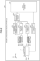
- FIG. 6 is a diagram illustrating an example of a configuration of the data processing device 100 according to the embodiment including a neural network according to the learned model.
- the complex first vector data is the input data during learning.
- the complex first vector data is a magnetic resonance imaging image of a complex value obtained based on collected data collected by a magnetic resonance imaging apparatus.
- the intermediate layer 5 that is, the n-th layer of the neural network 7 according to the embodiment performs a linear operation on an input vector 5a to which the output result from the n-1-th layer is input.
- the intermediate layer 5 includes the linear layer 5b disposed in the preceding stage of a division processing layer 5x, the division processing layer 5x disposed in the subsequent stage of the linear layer 5b, the nonlinear layer 5c disposed in the subsequent stage of the division processing layer, and a multiplication processing layer 5y disposed in the subsequent stage of the nonlinear layer 5c.
- the output result of the output unit of the division processing layer of the n-1-th layer becomes the input vector 5a
- the output result of the output unit of the multiplication processing layer 5y becomes an input vector 6a of the n+1-th layer.
- the complex first vector data that is, the input data during learning
- the division processing layer 5x and the multiplication processing layer 5y are connected to second vector data 10 that is the second vector data containing the features of the complex first vector data, that is, the input data during learning.
- the input vector 5a, the second vector data 10, and the like are complex number data.
- the data of the real part and the data of the imaginary part may be held separately as separate data.
- the data output from the n-1-th layer is input as the input vector 5a.
- the data output from the division processing layer 5a of the n-1-th layer is output as the input vector 5a.
- the input vector 5a is complex vector data.
- the linear layer 5b performs a linear operation on the input data that is input to the n-th layer, that is, the input vector 5a.
- the division processing layer 5x divides the output result of the linear layer 5b by the complex second vector data 10 containing the features of the input data during learning. That is, the division processing layer 5x divides the input complex first vector data by the complex second vector data containing the features of the first vector data.
- the second vector data 10 includes maps such as a sensitivity map, a B0 (static magnetic field) map, a B1 (high frequency magnetic field) map, and a noise map. That is, examples of the second vector data 10 include maps that represent the features of the sensitivity map, B0 map, B1 map, noise map, and the like, and maps represented by complex numbers.
- examples of the second vector data 10 also include the sensitivity map, B0 map, B1 map, noise map, and the like that are used without any change.
- the complex vector data is basically selected.
- the second vector data is typically data including a phase component or an intensity component that correlates with the first vector data.
- the meaning of the division processing layer 5x performing scaling by dividing with the second vector data 10 will now be described.
- by dividing the second vector data 10 it is possible to extract the intensity of the amplitude component of the first vector data relative to the amplitude component of the second vector data, and learn the relative intensity.
- the division processing layer 5x normalizes the phase or intensity of the first vector data by the division process. As a result, it is possible to improve the learning stability on the input data during learning.
- the nonlinear layer 5c performs activation by performing a nonlinear operation on the output result of the division processing layer 5x by applying a nonlinear function.
- the method of expanding the nonlinear function defined for the real number into the complex number is not limited to the above.
- the function to be expanded is not limited to ReLU, and may also be obtained by expanding a generally known activation function such as LeakyReLU, ELU, CELU, GELU, SELU, Swish, SoftShrink, HardShrink, Sigmoid, and TanhShrink.
- the domain of the functions may be shifted, or a part or all constants that characterize the functions may be replaced with learnable parameters.
- the multiplication processing layer 5y multiplies the output result of the nonlinear layer 5c by the second vector data to calculate a complex feature map. In this manner, the data on which scaling is performed by the division processing layer is restored by the multiplication processing layer.
- the multiplication processing layer 5y outputs the complex feature map, that is the result of multiplication, as the output data of the n-th layer, and inputs the output data to the n+1-th layer as the input vector 6a.
- the embodiment is not limited to the example described above.
- a BatchNormalization layer may be provided between the division processing layer 5x and the nonlinear layer 5c, or a Dropout layer may be provided subsequent to the nonlinear layer 5c or subsequent to the multiplication processing layer 5y.
- the data processing device 100 performs scaling on the input data by the division processing layer. As a result, it is possible to improve the learning stability on the phase and amplitude of the input data during learning, and improve the image quality of the output image.
- the second vector data 10 that is data used for scaling is provided in advance.
- the embodiment is not limited thereto.
- the second vector data is obtained as an output result of another neural network.
- FIG. 7 illustrates an example of such a configuration.
- the neural network 20 may or may not include a learning parameter.
- the neural network 20 is preferably a linear network without a nonlinear operation and a bias term.
- the input vector 5a is input to the input side of the neural network 20, and the second vector data 10 is output from the output side of the neural network 20. That is, in the second embodiment, the input vector 5a is input to the second neural network 20, and the second vector data 10, that is, data used for scaling is generated as the output result of the second neural network 20. That is, in the second embodiment, the second vector data 10 is the output data obtained by inputting input data to the second neural network 20 that is different from the neural network 7.
- the second neural network 20 may be the same neural network for each layer in the neural network 7, or may be a neural network in which the internal parameter changes with each layer.
- the scaling is performed on the basis of the second vector data generated by the other neural network.
- the embodiment is not limited to the example described above, and many variations of the embodiment are possible.
- the division processing layer 5x is disposed subsequent to the linear layer 5b.
- the embodiment is not limited thereto.
- the division processing layer 5x is disposed in front of the linear layer 5b. That is, in the third embodiment, the linear layer 5b is disposed in the subsequent stage of the division processing layer 5x, and is disposed in the preceding stage of the multiplication processing layer 5y.
- each layer in the neural network 7 of the learned model according to the third embodiment includes the division processing layer 5x to which the input vector 5a is input, the linear layer 5b disposed in the subsequent stage of the division processing layer 5x, the nonlinear layer 5c disposed in the subsequent stage of the linear layer 5b, and the multiplication processing layer 5y disposed in the subsequent stage of the nonlinear layer 5c.
- the division processing layer 5x divides the input data that is input to the input layer 5a in each layer by the second vector data.
- the linear layer 5b performs a linear operation on the output result of the division processing layer 5x.
- the nonlinear layer 5c performs a nonlinear operation on the output result of the linear layer 5b.
- the multiplication processing layer 5y multiplies the output result of the nonlinear layer 5c by the second vector data 10, and outputs the result of multiplication as the output data of the layer.
- the third embodiment it may be possible to improve the image quality of the output image, by disposing the division processing layer 5x in the preceding stage of the linear layer 5b.
- the embodiment is not limited to the example described above.
- the division and multiplication using the second vector data are performed in each layer.
- the embodiment is not limited thereto.
- the division process and the multiplication process using the second vector data 10 may only be performed once in each of the first layer and the last layer.
- FIG. 9 illustrates such a situation.
- the intermediate layer 3 represents the foremost layer among the layers of the neural network 7, and an intermediate layer 8 represents the last layer among the layers of the neural network 7.
- the intermediate layer 3 includes the linear layer 3b to which an input vector 3a is input, a division processing layer 3x, and the nonlinear layer 3c.
- the intermediate layer 8 includes a linear layer 8b to which an input vector 8a is input, a nonlinear function 8c, and a multiplication processing layer 8y. That is, the division processing layer 3x is disposed in the frontmost layer among the layers of the neural network 7, and the multiplication processing layer 8y is disposed in the last layer among the layers of the neural network.
- the division processing layer 3x is disposed in the foremost layer and the multiplication processing layer 8y is disposed in the last layer.
- FIG. 10 is a diagram illustrating an example of a configuration of the neural network 7 according to the fifth embodiment.
- the third vector data 30 is data for generating second vector data 10a, 10b, and the like that are data used for scaling.
- the third vector data 30 is data on a map of sensitivity, B0, or noise, and the like.
- the third vector data 30 may also be the first vector data, or may also be data generated using multiple data among maps of the first vector data, sensitivity, B0, B1, or noise.
- neural networks 20a and 20b are neural networks themselves, and output data according to the input of certain data.
- the neural network 20a outputs the second vector data 10a on the basis of the input vector 5a and the third vector data.
- the neural network 20b outputs the second vector data 10b on the basis of the input vector 6a, the second vector data 10a, and the input from the neural network 20a.
- the division processing layer 5x divides the output result from the linear layer 5b by the second vector data 10a, and outputs the result of the division process to the nonlinear layer 5c.
- the multiplication processing layer 5y multiplies the output result of the nonlinear layer 5c by the second vector data 10b, and outputs the result of the multiplication process as the input vector 6a.
- a division processing layer 6x divides the output result from a linear layer 6b by the second vector data 10b, and outputs the result of the division process to a nonlinear layer 6c.
- a multiplication processing layer 6y multiplies the output result of the nonlinear layer 6c by the second vector data 10b, and outputs the result of the multiplication process.
- the second vector data is the output data obtained by inputting the input data obtained from the third vector data 30, to the second neural network that is different from the neural network 7.
- the second vector data that is data used for scaling is data used for scaling as the output result of the neural network for each layer, it is possible to change the second vector data in each layer, and perform scaling in a flexible manner.
Landscapes
- Engineering & Computer Science (AREA)
- Physics & Mathematics (AREA)
- Health & Medical Sciences (AREA)
- General Health & Medical Sciences (AREA)
- Theoretical Computer Science (AREA)
- Biomedical Technology (AREA)
- Life Sciences & Earth Sciences (AREA)
- General Physics & Mathematics (AREA)
- Artificial Intelligence (AREA)
- Nuclear Medicine, Radiotherapy & Molecular Imaging (AREA)
- Data Mining & Analysis (AREA)
- Molecular Biology (AREA)
- Biophysics (AREA)
- Computing Systems (AREA)
- General Engineering & Computer Science (AREA)
- Mathematical Physics (AREA)
- Software Systems (AREA)
- Radiology & Medical Imaging (AREA)
- Evolutionary Computation (AREA)
- Computational Linguistics (AREA)
- Public Health (AREA)
- Medical Informatics (AREA)
- High Energy & Nuclear Physics (AREA)
- Condensed Matter Physics & Semiconductors (AREA)
- Signal Processing (AREA)
- Computer Vision & Pattern Recognition (AREA)
- Primary Health Care (AREA)
- Pathology (AREA)
- Epidemiology (AREA)
- Databases & Information Systems (AREA)
- Heart & Thoracic Surgery (AREA)
- Surgery (AREA)
- Animal Behavior & Ethology (AREA)
- Veterinary Medicine (AREA)
- Image Processing (AREA)
- Magnetic Resonance Imaging Apparatus (AREA)
Abstract
A data processing device according to an embodiment includes a processing circuit (110). The processing circuit (110) performs data processing using a learned model with a neural network including a division processing layer (7x) that divides input complex first vector data by complex second vector data containing features of the first vector data, a nonlinear layer (7c) that is disposed in the subsequent stage of the division processing layer (7x) and that performs a nonlinear operation, and a multiplication processing layer (7y) that is disposed in the subsequent stage of the nonlinear layer (7c) and that multiplies the input data by the second vector data.
Description
- Embodiments described herein relate generally to a data processing device, a magnetic resonance imaging apparatus, and a data processing method.
- In machine learning using a neural network, a real-valued neural network is used as a standard.
- However, in the medical data processing device such as a magnetic resonance imaging apparatus and an ultrasonic diagnostic device, signal processing using complex numbers is often used. Hence, various applications are possible by using a complex-valued neural network.
- In this example, for example, in a medical image such as a magnetic resonance image and an ultrasonic image, while the phase information of an image, for example, the gradient of the phase, is often important, the absolute value of the phase seldom has significant implications. For example, in the magnetic resonance imaging apparatus, a slight difference in the center frequency appears as a phase modulation of the entire image. However, in many cases, the importance of the absolute values of the phases is relatively low.
- Thus, for example, when the complex-valued neural network is applied to a medical image for noise removal, region extraction, and the like, it is desirable to configure the neural network such that the output result does not vary significantly with respect to the phase modulation of the entire image, while the phase information of the input image is not ignored.
- A data processing device provided in one aspect of the present invention includes a processing circuit that performs data processing using a learned model with a neural network that includes a division processing layer that divides input complex first vector data by complex second vector data containing a feature of the first vector data, a nonlinear layer that is disposed in a subsequent stage of the division processing layer and that performs a nonlinear operation, and a multiplication processing layer that is disposed in a subsequent stage of the nonlinear layer and that multiplies the input data by the second vector data.
- The processing circuit may be configured to apply the learned model to an input image.
- The processing circuit may also output complex vector data.
- The neural network may also include a linear layer that performs a linear operation.
- The linear layer may also be disposed in a preceding stage of the division processing layer.
- The linear layer may also be disposed in a subsequent stage of the division processing layer and in a preceding stage of the multiplication processing layer.
- The second vector data may also be a map of sensitivity, B0, B1, or noise.
- The second vector data may also be data obtained by inputting input data to a second neural network that is different from the neural network.
- The division processing layer may also be disposed in the foremost layer among layers of the neural network, and the multiplication processing layer may also be disposed in the last layer among the layers of the neural network.
- The second vector data may also be output data obtained by inputting input data obtained from third vector data, to a second neural network that is different from the neural network.
- The third vector data may also be a map of the first vector data, sensitivity, B0, B1, or noise, or may be data generated using multiple data among maps of the first vector data, sensitivity, B0, B1, or noise.
- The multiplication processing layer may multiply the output result of the nonlinear layer by the second vector data.
- The learned model may also include
- a linear layer that performs a linear operation on input data, wherein
- the division processing layer may divide the output result of the linear layer by the second vector data,
- the nonlinear layer may perform the nonlinear operation on the output result of the division processing layer, and
- the multiplication processing layer may multiply the output result of the nonlinear layer by the second vector data, and output the result of multiplication as the output data of the layer.
- The learned model may also include
- a linear layer that performs a linear operation on input data, wherein
- the division processing layer may divide the input data that is input by the second vector data,
- the linear layer may perform the linear operation on the output result of the division processing layer,
- the nonlinear layer may perform the nonlinear operation on the output result of the linear layer, and
- the multiplication processing layer may multiply the output result of the nonlinear layer by the second vector data, and output the result of multiplication as the output data of the layer.
- The second vector data may also be data including a phase component or an intensity component that correlates with the first vector data.
- The division processing layer may also normalize the phase or intensity of the first vector data by a division process.
- The nonlinear layer may also include a function obtained by expanding a nonlinear real function into a complex number.
- A magnetic resonance imaging apparatus provided in one aspect of the present invention includes a processing circuit that performs data processing using a learned model with a neural network that includes a division processing layer that divides input complex first vector data by complex second vector data containing a feature of the first vector data, a nonlinear layer that is disposed in a subsequent stage of the division processing layer and that performs a nonlinear operation, and a multiplication processing layer that is disposed in a subsequent stage of the nonlinear layer and that multiplies the input data by the second vector data.
- A data processing method provided in one aspect of the present invention performs data processing using a learned model with a neural network that includes a division processing layer that divides input complex first vector data by complex second vector data containing a feature of the first vector data, a nonlinear layer that is disposed in a subsequent stage of the division processing layer and that performs a nonlinear operation, and a multiplication processing layer that is disposed in a subsequent stage of the nonlinear layer and that multiplies the input data by the second vector data.
- The input complex first vector data and the output vector data may be the same size as each other, and may be the same size for each layer.
- The second vector data may be a two-dimensional array of the same size as the input complex first vector data.
- The input complex first vector data may be generated from received magnetic resonance data and the second vector data may be generated from the same received magnetic resonance data (for each new input).
- The second vector data may be a sensitivity map, a B0 (static magnetic field) map, a B1 (high frequency magnetic field) map, or a noise map generated from the received magnetic resonance data.
- A data processing device provided in one aspect of the present invention includes a processing circuit that performs learning to generate a learned model with a neural network that includes a division processing layer that divides input complex first vector data by complex second vector data containing a feature of the first vector data, a nonlinear layer that is disposed in a subsequent stage of the division processing layer and that performs a nonlinear operation, and a multiplication processing layer that is disposed in a subsequent stage of the nonlinear layer and that multiplies the input data by the second vector data.
- A data processing method provided in one aspect of the present invention performs learning to generate a learned model with a neural network that includes a division processing layer that divides input complex first vector data by complex second vector data containing a feature of the first vector data, a nonlinear layer that is disposed in a subsequent stage of the division processing layer and that performs a nonlinear operation, and a multiplication processing layer that is disposed in a subsequent stage of the nonlinear layer and that multiplies the input data by the second vector data.
-
-
FIG. 1 is a diagram illustrating an example of a data processing device according to an embodiment; -
FIG. 2 is a diagram illustrating an example of a magnetic resonance imaging apparatus according to the embodiment; -
FIG. 3 is a diagram illustrating an example of an ultrasonic diagnostic device according to the embodiment; -
FIG. 4 is a diagram illustrating an example of a neural network according to the embodiment; -
FIG. 5 is a diagram for explaining a neural network according to the embodiment; -
FIG. 6 is a diagram illustrating an example of a configuration of a data processing device according to a first embodiment; -
FIG. 7 is a diagram illustrating an example of a configuration of a data processing device according to a second embodiment; -
FIG. 8 is a diagram illustrating an example of a configuration of a data processing device according to a third embodiment; -
FIG. 9 is a diagram illustrating an example of a configuration of a data processing device according to a fourth embodiment; and -
FIG. 10 is a diagram illustrating an example of a configuration of a data processing device according to a fifth embodiment. - A data processing device provided in one aspect of the present invention includes a processing circuit. The processing circuit performs data processing using a learned model with a neural network that includes a division processing layer that divides input complex first vector data by complex second vector data containing the features of the first vector data, a nonlinear layer that is disposed in the subsequent stage of the division processing layer and that performs a nonlinear operation, and a multiplication processing layer that is disposed in the subsequent stage of the nonlinear layer and that multiplies the input data by the second vector data.
- Hereinafter, a data processing device, a magnetic resonance imaging apparatus, and a data processing method according to an embodiment will be described in detail with reference to the accompanying drawings.
- With reference to
FIG. 1 , a configuration of adata processing device 100 according to the embodiment will be described. - The
data processing device 100 is a device that generates data using machine learning. For example, thedata processing device 100 is connected to various medical image diagnostic devices such as the magnetic resonance imaging apparatus illustrated inFIG. 2 and the ultrasonic diagnostic device illustrated inFIG. 3 . Thedata processing device 100 performs processing such as processing a signal received from the medical image diagnostic device, generating a learned model, and executing the learned model. Examples of the medical image diagnostic device to which thedata processing device 100 is connected are not limited to the magnetic resonance imaging apparatus and the ultrasonic diagnostic device, but may also be other devices such as an X-ray CT device and a PET device. - The
data processing device 100 is typically a medical data processing device that processes medical data. However, in the embodiment, thedata processing device 100 is not limited to the medical data processing device. As an example, thedata processing device 100 may be a device for processing magnetic resonance data that is not medical data. - The
data processing device 100 includes aprocessing circuit 110, amemory 132, an input device 134, and a display 135. Theprocessing circuit 110 includes a trainingdata generation function 110a, alearning function 110b, aninterface function 110c, acontrol function 110d, anapplication function 110e, anacquisition function 110f, and a scaledata acquisition function 110g. - In the embodiment, each processing function performed by the training
data generation function 110a, thelearning function 110b, theinterface function 110c, thecontrol function 110d, theapplication function 110e, theacquisition function 110f, and the scaledata acquisition function 110g, and a learned model (for example, a neural network) are stored in thememory 132 in the form of computer executable programs. Theprocessing circuit 110 is a processor that implements a function corresponding to each computer program, by reading a computer program from thememory 132 and executing the computer program. In other words, theprocessing circuit 110 in a state in which each computer program is read has each function illustrated in theprocessing circuit 110 inFIG. 1 . Moreover, theprocessing circuit 110 in a state in which a computer program corresponding to a learned model (neural network) is read can perform the processing according to the learned model. InFIG. 1 , the functions of theprocessing circuit 110 are implemented by a single processing circuit. However, the functions of theprocessing circuit 110 may also be implemented by configuring theprocessing circuit 110 by combining a plurality of independent processors, and causing each of the processors to execute a computer program. In other words, each of the functions described above may be configured as a computer program, and a single processing circuit may execute each computer program. Moreover, a single processing circuit may implement two or more functions of theprocessing circuit 110. As another example, a specific function may be implemented in a dedicated independent program execution circuit. - In
FIG. 1 , theprocessing circuit 110, the trainingdata generation function 110a, thelearning function 110b, theinterface function 110c, thecontrol function 110d, theapplication function 110e, theacquisition function 110f, and the scaledata acquisition function 110g are examples of a processing unit, a generation unit, an input unit (learning unit), a reception unit, a control unit, an application unit, an acquisition unit, and a scale data acquisition unit, respectively. - For example, the term "processor" used in the above description refers to a central processing unit (CPU), a graphical processing unit (GPU), or a circuit such as an application specific integrated circuit (ASIC) and a programmable logic device (for example, a simple programmable logic device (SPLD), a complex programmable logic device (CPLD), and a field programmable gate array (FPGA)). The processor implements the function by reading and executing a computer program stored in the
memory 132. - Moreover, instead of storing a computer program in the
memory 132, the computer program may also be directly incorporated in a circuit of the processor. In this case, the processor implements the function by reading and executing a computer program incorporated in the circuit. Thus, for example, instead of storing a learned model in thememory 132, a computer program according to the learned model may be directly incorporated in the circuit of the processor. - When the
processing circuit 110 is incorporated in various medical image diagnostic devices, or when the processing is performed in conjunction with various medical image diagnostic devices, theprocessing circuit 110 may also have a function that can execute the process associated with the above. - With the training
data generation function 110a, theprocessing circuit 110 generates training data for learning, on the basis of the data and images acquired by theinterface function 110c. - With the
learning function 110b, theprocessing circuit 110 generates a learned model, by performing learning using the training data generated by the trainingdata generation function 110a. With theinterface function 110c, theprocessing circuit 110 acquires the data, images, and the like for image generation by theapplication function 110e, from thememory 132. - With the
control function 110d, theprocessing circuit 110 controls the overall processing of thedata processing device 100. More specifically, with thecontrol function 110d, theprocessing circuit 110 controls the processing of theprocessing circuit 110, on the basis of various setting requests input from an operator via the input device 134, and various control programs and various types of data read from thememory 132. - Moreover, with the
application function 110e, theprocessing circuit 110 generates an image on the basis of the results of processing performed using the trainingdata generation function 110a and thelearning function 110b. Furthermore, with theapplication function 110e, theprocessing circuit 110 applies the learned model generated by thelearning function 110b to an input image, and generates an image on the basis of the application results of the learned model. Still furthermore, with theacquisition function 110f, theprocessing circuit 110 acquires various types of data. Still furthermore, with the scaledata acquisition function 110g, theprocessing circuit 110 acquires scale data, which will be described below. - The
memory 132 includes a semiconductor memory element such as a random access memory (RAM) and a flash memory, a hard disk, an optical disc, and the like. Thememory 132 is a memory that stores data such as image data for display generated by theprocessing circuit 110, and image data for training. Thememory 132 stores various types of data such as a control program for image processing and display processing, as necessary. - The input device 134 receives various instructions and information input by the operator. For example, the input device 134 is a pointing device such as a mouse or a trackball, a selection device such as a mode change-over switch, or an input device such as a keyboard.
- Under the control of the
control function 110d and the like, the display 135 displays a graphical user interface (GUI) for receiving an input of imaging conditions, an image generated by thecontrol function 110d, and the like. For example, the display 135 is a display device such as a liquid crystal display. The display 135 is an example of a display unit. The display 135 includes a mouse, a keyboard, a button, a panel switch, a touch command screen, a foot switch, a trackball, a joystick, and the like. -
FIG. 2 is an example of a magneticresonance imaging apparatus 200 incorporated with thedata processing device 100 according to the embodiment. - As illustrated in
FIG. 2 , the magneticresonance imaging apparatus 200 includes a staticmagnetic field magnet 201, a static magnetic field power supply (not illustrated), agradient coil 203, a gradient magneticfield power supply 204, acouch 205, acouch control circuit 206, atransmitter coil 207, atransmitter circuit 208, areceiver coil 209, areceiver circuit 210, a sequence control circuit 220 (sequence control unit), and thedata processing device 100 described inFIG. 1 . The magneticresonance imaging apparatus 200 does not include a subject P (for example, human body). Moreover, the configuration illustrated inFIG. 2 is merely an example. - The static
magnetic field magnet 201 is a magnet formed in a substantially hollow cylindrical shape, and generates a static magnetic field in the interior space. For example, the staticmagnetic field magnet 201 is a superconducting magnet and the like, and is excited by receiving supply of electric current from the static magnetic field power supply. The static magnetic field power supply supplies electric current to the staticmagnetic field magnet 201. As another example, the staticmagnetic field magnet 201 may also be a permanent magnet. In this case, the magneticresonance imaging apparatus 200 need not be equipped with a static magnetic field power supply. Moreover, the static magnetic field power supply may be provided separately from the magneticresonance imaging apparatus 200. - The
gradient coil 203 is a coil formed in a substantially hollow cylindrical shape, and is placed inside the staticmagnetic field magnet 201. Thegradient coil 203 is formed by combining three coils corresponding to X, Y, and Z axes that are orthogonal to each other. These three coils individually receive electric current from the gradient magneticfield power supply 204, and generate gradient magnet fields in which the magnetic field intensity changes along the X, Y, and Z axes. For example, the gradient magnetic fields of the X, Y, and Z axes generated by thegradient coil 203 are a slice gradient magnetic field Gs, a phase encoding gradient magnetic field Ge, and a readout gradient magnetic field Gr. The gradient magneticfield power supply 204 supplies electric current to thegradient coil 203. - The
couch 205 includes acouchtop 205a on which the subject P is placed. Under the control of thecouch control circuit 206, while the subject P is placed thereon, the couchtop 205a is inserted into the cavity (imaging port) of thegradient coil 203. In general, thecouch 205 is installed so that the longitudinal direction is parallel to the center axis of the staticmagnetic field magnet 201. Under the control of thedata processing device 100, thecouch control circuit 206 moves the couchtop 205a in the longitudinal direction and the vertical direction, by driving thecouch 205. - The
transmitter coil 207 is placed inside thegradient coil 203, and a high-frequency magnetic field is generated by receiving the supply of RF pulses from thetransmitter circuit 208. Thetransmitter circuit 208 supplies RF pulses corresponding to the Larmor frequency that is determined by the type of target atom and the magnetic field intensity, to thetransmitter coil 207. - The
receiver coil 209 is placed inside thegradient coil 203 to receive a magnetic resonance signal (hereinafter, referred to as an "MR signal" as necessary) emitted from the subject P under the influence of a high-frequency magnetic field. Upon receiving the magnetic resonance signal, thereceiver coil 209 outputs the received magnetic resonance signal to thereceiver circuit 210. - The
transmitter coil 207 and thereceiver coil 209 described above are merely examples. Thetransmitter coil 207 and thereceiver coil 209 may be configured by combining one or a plurality of a coil equipped only with a transmission function, a coil equipped only with a reception function, and a coil equipped with transmission and reception functions. - The
receiver circuit 210 detects the magnetic resonance signal output from thereceiver coil 209, and generates magnetic resonance data on the basis of the detected magnetic resonance signal. More specifically, thereceiver circuit 210 generates magnetic resonance data by digitally converting the magnetic resonance signal output from thereceiver coil 209. Moreover, thereceiver circuit 210 transmits the generated magnetic resonance data to thesequence control circuit 220. Thereceiver circuit 210 may also be provided on the side of the gantry device including the staticmagnetic field magnet 201, thegradient coil 203, and the like. - On the basis of sequence information, the
sequence control circuit 220 drives the gradient magneticfield power supply 204, thetransmitter circuit 208, and thereceiver circuit 210 to capture images of the subject P. In this example, the sequence information is information that defines the procedure for imaging. In the sequence information, the intensity of electric current supplied to thegradient coil 203 by the gradient magneticfield power supply 204 and the timing at which the electric current is supplied, the intensity of the RF pulse supplied to thetransmitter coil 207 by thetransmitter circuit 208 and the timing at which the RF pulse is applied, and the timing at which the magnetic resonance signal is detected by thereceiver circuit 210, and the like are defined. For example, thesequence control circuit 220 is an integrated circuit such as an application specific integrated circuit (ASIC) and a field programmable gate array (FPGA), and an electronic circuit such as a central processing unit (CPU) and a micro processing unit (MPU). Thesequence control circuit 220 is an example of a scanning unit. - Moreover, upon receiving magnetic resonance data from the
receiver circuit 210 as a result of capturing an image of the subject P by driving the gradient magneticfield power supply 204, thetransmitter circuit 208, and thereceiver circuit 210, thesequence control circuit 220 transfers the received magnetic resonance data to thedata processing device 100. In addition to the processing described inFIG. 1 , thedata processing device 100 performs the overall control of the magneticresonance imaging apparatus 200. - Returning to
FIG. 1 , the processing performed by thedata processing device 100 and that is different from the processing described inFIG. 1 will be described. With theinterface function 110c, theprocessing circuit 110 transmits sequence information to thesequence control circuit 220, and receives magnetic resonance data from thesequence control circuit 220. Moreover, upon receiving the magnetic resonance data, theprocessing circuit 110 with theinterface function 110c stores the received magnetic resonance data in thememory 132. - With the
control function 110d, the magnetic resonance data stored in thememory 132 is disposed in k-space. As a result, thememory 132 stores the k-space data. - The
memory 132 stores the magnetic resonance data received by theprocessing circuit 110 with theinterface function 110c, the k-space data disposed in the k-space by theprocessing circuit 110 with thecontrol function 110d, image data generated by theprocessing circuit 110 with the generation function (or theapplication function 110e), and the like. - With the
control function 110d, theprocessing circuit 110 performs the overall control of the magneticresonance imaging apparatus 200, and controls imaging, the generation of an image, the display of the image, and the like. For example, theprocessing circuit 110 with thecontrol function 110d receives an input of imaging conditions (imaging parameters and the like) on the GUI, and generates sequence information according to the received imaging conditions. Moreover, theprocessing circuit 110 with thecontrol function 110d transmits the generated sequence information to thesequence control circuit 220. - With the generation function not illustrated in
FIG. 1 (or theapplication function 110e), theprocessing circuit 110 generates a magnetic resonance image, by reading the k space data from thememory 132 and applying reconstruction processing such as Fourier transform on the read k space data. -
FIG. 3 is a configuration example of an ultrasonic diagnostic devicemain body 300 incorporated with thedata processing device 100 according to the embodiment. The ultrasonic diagnostic device according to the embodiment includes anultrasonic probe 305 and the ultrasonic diagnostic devicemain body 300. The ultrasonic diagnostic devicemain body 300 includes atransmitter circuit 309, a receiver circuit 311, and thedata processing device 100 described above. - The
ultrasonic probe 305 has a plurality of piezoelectric transducer elements. The piezoelectric transducer elements generate ultrasonic waves on the basis of a drive signal supplied from thetransmitter circuit 309 included in the ultrasonic diagnostic devicemain body 300, which will be described below. The piezoelectric transducer elements in theultrasonic probe 305 receive reflected waves from the subject P, and convert the received reflected waves into electrical signals (reflected wave signals). Theultrasonic probe 305 has a matching layer on the piezoelectric transducer element, a backing material that prevents the ultrasonic waves from propagating from the piezoelectric transducer element to the rear, and the like. Theultrasonic probe 305 is detachably connected to the ultrasonic diagnostic devicemain body 300. Moreover, theultrasonic probe 305 is an example of a scanning unit. - When ultrasonic waves are transmitted from the
ultrasonic probe 305 to the subject P, the transmitted ultrasonic waves are reflected successively by the discontinuous surface of the acoustic impedance in the body tissue of the subject P, received by the piezoelectric transducer elements of theultrasonic probe 305, and are converted into reflected wave signals. The amplitude of the reflected wave signal depends on the difference in acoustic impedance on the discontinuous surface that reflects the ultrasonic waves. When the transmitted ultrasonic pulse is reflected by the moving blood flow or the surface of the heart wall or the like, the reflected wave signal depends on the velocity component of the moving body with respect to the ultrasonic wave transmission direction due to Doppler effect, and undergoes a frequency shift. - The ultrasonic diagnostic device
main body 300 is a device that generates ultrasonic image data on the basis of the reflected wave signal received from theultrasonic probe 305. The ultrasonic diagnostic devicemain body 300 is a device capable of generating two-dimensional ultrasonic image data on the basis of a two-dimensional reflected wave signal, and that is capable of generating three-dimensional ultrasonic image data on the basis of a three-dimensional reflected wave signal. However, the embodiment is applicable even if the ultrasonic diagnostic device is a device dedicated to two-dimensional data. - As illustrated in
FIG. 3 , the ultrasonicdiagnostic device 10 includes thetransmitter circuit 309, the receiver circuit 311, and thedata processing device 100. - The
transmitter circuit 309 and the receiver circuit 311 control the ultrasonic transmission and reception performed by theultrasonic probe 305, on the basis of the instruction of thedata processing device 100 with a control function. Thetransmitter circuit 309 includes a pulse generator, a transmission delay unit, a pulser, and the like, and supplies a drive signal to theultrasonic probe 305. The pulse generator repeatedly generates a rate pulse for forming transmission ultrasonic waves at a certain pulse repetition frequency (PRF). Moreover, the transmission delay unit provides a delay time of each piezoelectric transducer element necessary for focusing the ultrasonic waves generated from theultrasonic probe 305 into a beam shape and for determining the transmission directivity, to each rate pulse generated by the pulse generator. Furthermore, the pulser applies a drive signal (drive pulse) to theultrasonic probe 305 at a timing based on the rate pulse. - That is, the transmission delay unit optionally adjusts the transmission direction of the ultrasonic waves transmitted from the piezoelectric transducer element surface, by changing the delay time provided to each rate pulse. Moreover, the transmission delay unit controls the position of the focusing point (transmission focus) in the depth direction of the ultrasonic wave transmission, by changing the delay time provided to each rate pulse.
- Furthermore, the receiver circuit 311 includes an amplifier circuit, an analog/digital (A/D) converter, a reception delay circuit, an adder, a quadrature detection circuit, and the like, and generates a reception signal (reflected wave data), by performing various processes on the reflected wave signal received from the
ultrasonic probe 305. The amplifier circuit performs gain correction processing by amplifying the reflected wave signal for each channel. The A/D converter performs A/D conversion on the gain-corrected reflected wave signal. The reception delay circuit provides a reception delay time necessary for determining the reception directivity to digital data. The adder performs addition processing on the reflected wave signal to which the reception delay time is given by the reception delay circuit. The addition processing of the adder emphasizes the reflected component from the direction corresponding to the reception directivity of the reflected wave signal. Then, the quadrature detection circuit converts the output signal of the adder into an in-phase signal (I signal, I: In-phase) and a quadrature signal (Q signal, Q: Quadrature-phase) in the baseband. Then, the quadrature detection circuit transmits the I signal and Q signal (hereinafter referred to as IQ signals) to theprocessing circuit 110 as reception signals (reflected wave data). The quadrature detection circuit may also convert the output signal of the adder into a radio frequency (RF) signal and transmit the RF signal to theprocessing circuit 110. The IQ signal and the RF signal will be reception signals with phase information. - To scan a two-dimensional region in the subject P, the
transmitter circuit 309 causes theultrasonic probe 305 to transmit an ultrasonic beam for scanning the two-dimensional region. Then, the receiver circuit 311 generates a two-dimensional reception signal from the two-dimensional reflected wave signal received from theultrasonic probe 305. Moreover, to scan a three-dimensional region in the subject P, thetransmitter circuit 309 causes theultrasonic probe 305 to transmit an ultrasonic beam for scanning the three-dimensional region. Then, the receiver circuit 311 generates a three-dimensional reception signal from the three-dimensional reflected wave signal received from theultrasonic probe 305. The receiver circuit 311 generates a receive signal on the basis of the reflected wave signal, and transmits the generated reception signal to theprocessing circuit 110. - The
transmitter circuit 309 causes theultrasonic probe 305 to transmit an ultrasonic beam from a predetermined transmission position (transmission scanning line). At a predetermined reception position (reception scanning line), the receiver circuit 311 receives a signal based on the reflected wave of the ultrasonic wave beam transmitted from thetransmitter circuit 309, from theultrasonic probe 305. In the case of not performing parallel simultaneous reception, the transmission scanning line and the reception scanning line become the same scanning line. On the other hand, in the case of performing parallel simultaneous reception, when thetransmitter circuit 309 causes theultrasonic probe 305 to transmit one ultrasonic beam through one transmission scanning line, the receiver circuit 311 simultaneously receives the signal based on the reflected wave derived from the ultrasonic wave transmitted to theultrasonic probe 305 by thetransmitter circuit 309 at a plurality of predetermined reception positions (reception scanning lines) as a plurality of reception beams via theultrasonic probe 305. - The
data processing device 100 is connected to thetransmitter circuit 309 and the receiver circuit 311. In addition to the functions already illustrated inFIG. 1 , thedata processing device 100 performs processing such as processing a signal received from the receiver circuit 311, controlling thetransmitter circuit 309, generating a learned model, executing the learned model, and executing various image processing. In addition to the functions already illustrated inFIG. 1 , theprocessing circuit 110 includes a B-mode processing function, a Doppler processing function, a generation function, and the like. - Subsequently, with reference to
FIG. 4 andFIG. 5 , a configuration of a neural network according to the embodiment will be described. -
FIG. 4 illustrates a configuration of a neural network 7 included in the learned model according to the embodiment. As illustrated inFIG. 4 , the neural network 7 according to the embodiment includes aninput layer 7a, a linear layer 7b, a nonlinear processing layer 7c, anoutput layer 7d, adivision processing layer 7x, and amultiplication processing layer 7y. The neural network 7 according to the embodiment is configured by combining a plurality of the layers as appropriate. The data input to theinput layer 7a is typically vector data, in other words, an input vector. The input vector is input to an intermediate layer of the neural network 7. Moreover, the data output to theoutput layer 7d is typically vector data, in other words, an output vector. The output vector is output from the intermediate layer of the neural network 7. The neural network 7 according to the embodiment includes thedivision processing layer 7x and themultiplication processing layer 7y compared to a generalneural network 7a inFIG. 5 , which will be described below. A detailed explanation of these points is given below. - Subsequently, with reference to
FIG. 5 , a typical configuration of the neural network will be described.FIG. 5 illustrates an example of the interconnections between layers in theneural network 7a generally used for machine learning. Theneural network 7a typically includes an input layer, an output layer, andintermediate layers - In this example, each intermediate layer includes a linear layer and a layer according to the processing using nonlinear processing (hereinafter referred to as an activation layer or a nonlinear layer). For example, the
intermediate layer 3 includes alinear layer 3b and anonlinear layer 3c. Theintermediate layer 4 includes alinear layer 4b and anonlinear layer 4c. Theintermediate layer 5 includes alinear layer 5b and anonlinear layer 5c. Moreover, each layer includes multiple nodes (neurons). - In this example, to the complex-valued medical data, the
data processing device 100 according to the embodiment applies a linear layer with a complex number coefficient and nonlinear activation (activation function). - That is, in each layer, the
processing circuit 110 includes a linear layer that performs a linear operation on an input vector input to each layer, and a nonlinear operation layer that performs a nonlinear operation on the output result of the linear layer. For example, in a case of theintermediate layer 5, that is the n-th layer, theintermediate layer 5 includes thelinear layer 5b and thenonlinear layer 5c. - In this example, the linear layer performs a linear operation on the input data that is input to each layer. For example, if the number of elements of the input vector input to the
intermediate layer 5, that is, the n-th layer is mn, and the i-th element is the complex number zn,i, thelinear layer 5b outputs a vector in which the j-th element is the complex number Σi=1 m-nωn,i,jzn,i+bn,j, wherein j is a natural number. In this example, ωn,i,j is a weighting coefficient in the n-th linear layer, and bn,j is a certain constant known as a bias term. - Subsequently, the nonlinear layer applies a nonlinear function to the output result of the linear layer. As an example, the
nonlinear layer 5c applies an activation function f to the output result of thelinear layer 5b, and inputs the output result to the n+1-th layer, that is, the next layer. For example, when the activation function fn,j, that is, the nonlinear function to be applied is used, the output result zn+1,j in thenonlinear layer 5c is expressed by the following formula (1).
- In this manner, in each layer of the neural network 7, the final output result is obtained by applying the linear layer with a complex number coefficient and nonlinear activation (activation function) to the medical data with a complex value, and by sequentially outputting the results to the next layer.
- Returning to
FIG. 5 , with thelearning function 110b, theprocessing circuit 110 generates a learned model by training the neural network 7 that applies the linear layer with a complex number coefficient and the nonlinear function to the complex-valued medical data, using a method, which will be described below. For example, theprocessing circuit 110 stores the generated learned model in thememory 132 as necessary. - The input vector is typically a medical image or medical image data acquired from a medical image diagnostic device. For example, if the medical image diagnostic device is the magnetic
resonance imaging apparatus 200, the input vector is a magnetic resonance image. Moreover, for example, if the medical image diagnostic device is the ultrasonic diagnostic devicemain body 300, the input vector is an ultrasonic image. - Furthermore, the input vector may be a medical image, or various image data, projection data, intermediate data, or raw data before the medical image is generated.
- Still furthermore, for example, the output vector may be a medical image or medical image data, and similar to the input vector, the output vector may also be various projection data, intermediate data, or raw data before the medical image is generated. For example, if an object of the neural network 7 is to perform denoising, the data output from the
output layer 2 is a high quality image from which noise is removed, compared to the input image. Theprocessing circuit 110 outputs complex vector data as the output vector. - If the neural network 7 according to the embodiment is a convolutional neural network (CNN), for example, the input vector is data represented by a two-dimensional array of size 32 x 32 or the like, and for example, the output vector is data represented by a two-dimensional array of size 32 x 32 or the like. The size of the input vector and the size of the output vector may be the same or different. Similarly, the size of the output vector in the intermediate layer may be the same or different from the size of the input vector in the intermediate layer.
- Subsequently, generation of the learned model according to the embodiment, that is, a learning step will be described. For example, with the
learning function 110b, theprocessing circuit 110 generates a learned model by carrying out machine learning on the neural network 7. In this example, to carry out machine learning means to determine the weights in the neural network 7 including the input layer, theintermediate layers intermediate layer 3, a set of coefficients that characterizes the connection between theintermediate layer 3 and theintermediate layer 4, ..., and a set of coefficients that characterizes the connection between theintermediate layer 5 and the output layer. For example, with thelearning function 110b, theprocessing circuit 110 determines these sets of coefficients, using a back propagation method. - With the
learning function 110b, theprocessing circuit 110 carries out machine learning on the basis of training data that is supervised data including the input vector and the output vector, determines the weights between the layers, and generates a learned model in which the weights are determined. - In deep learning, self-encoding (autoencoder) can be used. In this case, the data required for machine learning need not be supervised data.
- Subsequently, a process of applying the learned model according to the embodiment will be described. First, for example, with the
application function 110e, theprocessing circuit 110 inputs an input medical image, that is, a clinical image to the learned model. For example, with theapplication function 110e, theprocessing circuit 110 inputs an input medical image, that is, a clinical image to the input layer of the neural network 7, that is, the learned model. Subsequently, with theapplication function 110e, theprocessing circuit 110 obtains the data output from the output layer of the neural network 7, that is, the learned model, as an output medical image. For example, the output medical image is a medical image on which a predetermined process such as noise removal is performed. In this manner, for example, with theapplication function 110e, theprocessing circuit 110 generates the output medical image on which a predetermined process such as noise removal is performed. As necessary, with thecontrol function 110d, theprocessing circuit 110 may also display the acquired output medical image on the display 135. - Subsequently, the background according to the embodiment will be described.
- In machine learning using a neural network, a real-valued neural network is used as a standard. However, in the medical data processing device such as a magnetic resonance imaging apparatus and an ultrasonic diagnostic device, signal processing using complex numbers is often used. Hence, various applications are possible by using a complex-valued neural network.
- In this example, for example, in a medical image such as a magnetic resonance image and an ultrasonic image, while the phase information of an image, for example, the gradient of the phase, is often important, the absolute value of the phase seldom has significant implications. For example, in the magnetic resonance imaging apparatus, a slight difference in the center frequency appears as a phase modulation of the entire image. However, in many cases, the importance of the absolute values of the phases is relatively low.
- Thus, for example, when the complex-valued neural network is applied to a medical image for noise removal, region extraction, and the like, it is desirable to configure the neural network such that the output result does not vary significantly with respect to the phase modulation of the entire image, while the phase information of the input image is not ignored.
- In view of such a background, in the neural network 7, the
data processing device 100 according to the embodiment includes the division processing layer that performs division by multiple vector data containing the features of the input data during learning, and a multiplication processing layer that performs multiplication by the multiple vector data. Thedata processing device 100 applies scaling with complex numbers before and after activation in the neural network 7. As a result, it is possible to improve the learning stability on the change in phase and the change in magnification of signal values. - Such a configuration will be described with reference to
FIG. 6. FIG. 6 is a diagram illustrating an example of a configuration of thedata processing device 100 according to the embodiment including a neural network according to the learned model. In the neural network according to the learned model according to the embodiment, the complex first vector data is the input data during learning. For example, the complex first vector data is a magnetic resonance imaging image of a complex value obtained based on collected data collected by a magnetic resonance imaging apparatus. - As illustrated in
FIG. 6 , theintermediate layer 5, that is, the n-th layer of the neural network 7 according to the embodiment performs a linear operation on aninput vector 5a to which the output result from the n-1-th layer is input. Theintermediate layer 5 includes thelinear layer 5b disposed in the preceding stage of adivision processing layer 5x, thedivision processing layer 5x disposed in the subsequent stage of thelinear layer 5b, thenonlinear layer 5c disposed in the subsequent stage of the division processing layer, and amultiplication processing layer 5y disposed in the subsequent stage of thenonlinear layer 5c. The output result of the output unit of the division processing layer of the n-1-th layer becomes theinput vector 5a, and the output result of the output unit of themultiplication processing layer 5y becomes aninput vector 6a of the n+1-th layer. - Moreover, the complex first vector data, that is, the input data during learning, is input to the first layer, and the output result is output from the output layer of the final layer. Furthermore, the
division processing layer 5x and themultiplication processing layer 5y are connected tosecond vector data 10 that is the second vector data containing the features of the complex first vector data, that is, the input data during learning. - The
input vector 5a, thesecond vector data 10, and the like are complex number data. However, for example, the data of the real part and the data of the imaginary part may be held separately as separate data. - Subsequently, the process in the n-th layer will be described. First, the data output from the n-1-th layer is input as the
input vector 5a. Typically, the data output from thedivision processing layer 5a of the n-1-th layer is output as theinput vector 5a. For example, theinput vector 5a is complex vector data. Subsequently, thelinear layer 5b performs a linear operation on the input data that is input to the n-th layer, that is, theinput vector 5a. - Subsequently, the
division processing layer 5x divides the output result of thelinear layer 5b by the complexsecond vector data 10 containing the features of the input data during learning. That is, thedivision processing layer 5x divides the input complex first vector data by the complex second vector data containing the features of the first vector data. In this example, thesecond vector data 10 includes maps such as a sensitivity map, a B0 (static magnetic field) map, a B1 (high frequency magnetic field) map, and a noise map. That is, examples of thesecond vector data 10 include maps that represent the features of the sensitivity map, B0 map, B1 map, noise map, and the like, and maps represented by complex numbers. However, examples of thesecond vector data 10 also include the sensitivity map, B0 map, B1 map, noise map, and the like that are used without any change. As thesecond vector data 10, the complex vector data is basically selected. For example, the second vector data is typically data including a phase component or an intensity component that correlates with the first vector data. - The meaning of the
division processing layer 5x performing scaling by dividing with thesecond vector data 10 will now be described. By performing such a process, it is possible to cancel the phase component included in thesecond vector data 10 from the first vector data of the input data, extract the phase component of the first vector data relative to the phase component included in the second vector data, and learn the phase component. As a result, it is possible to improve the learning stability of the neural network 7 on the phase. Similarly, by dividing thesecond vector data 10, it is possible to extract the intensity of the amplitude component of the first vector data relative to the amplitude component of the second vector data, and learn the relative intensity. In other words, thedivision processing layer 5x normalizes the phase or intensity of the first vector data by the division process. As a result, it is possible to improve the learning stability on the input data during learning. - Subsequently, the
nonlinear layer 5c performs activation by performing a nonlinear operation on the output result of thedivision processing layer 5x by applying a nonlinear function. An example of the nonlinear function used in this example is represented by the following function, for example.
- By applying ReLU to each of the real part and the imaginary part, it is possible to assume that this function is obtained by expanding the nonlinear function ReLU defined for the real number into the complex number.
- The method of expanding the nonlinear function defined for the real number into the complex number is not limited to the above. For example, it is also possible to expand the nonlinear real function into the complex number, by applying the nonlinear function only on the real part, or applying the nonlinear function to the absolute value portion of the complex number. That is, the
nonlinear layer 5c includes the function obtained by expanding the nonlinear real function into the complex number. - Moreover, the function to be expanded is not limited to ReLU, and may also be obtained by expanding a generally known activation function such as LeakyReLU, ELU, CELU, GELU, SELU, Swish, SoftShrink, HardShrink, Sigmoid, and TanhShrink. Furthermore, the domain of the functions may be shifted, or a part or all constants that characterize the functions may be replaced with learnable parameters.
- Subsequently, the
multiplication processing layer 5y multiplies the output result of thenonlinear layer 5c by the second vector data to calculate a complex feature map. In this manner, the data on which scaling is performed by the division processing layer is restored by the multiplication processing layer. Themultiplication processing layer 5y outputs the complex feature map, that is the result of multiplication, as the output data of the n-th layer, and inputs the output data to the n+1-th layer as theinput vector 6a. The embodiment is not limited to the example described above. For example, a BatchNormalization layer may be provided between thedivision processing layer 5x and thenonlinear layer 5c, or a Dropout layer may be provided subsequent to thenonlinear layer 5c or subsequent to themultiplication processing layer 5y. - In this manner, the
data processing device 100 according to the first embodiment performs scaling on the input data by the division processing layer. As a result, it is possible to improve the learning stability on the phase and amplitude of the input data during learning, and improve the image quality of the output image. - In the embodiment described above, the
second vector data 10 that is data used for scaling is provided in advance. However, the embodiment is not limited thereto. In the second embodiment, the second vector data is obtained as an output result of another neural network. -
FIG. 7 illustrates an example of such a configuration. In the second embodiment, there is a secondneural network 20 that is different from the neural network 7 including theintermediate layer 5, anintermediate layer 6, and the like. In this example, theneural network 20 may or may not include a learning parameter. However, theneural network 20 is preferably a linear network without a nonlinear operation and a bias term. - In this example, the
input vector 5a is input to the input side of theneural network 20, and thesecond vector data 10 is output from the output side of theneural network 20. That is, in the second embodiment, theinput vector 5a is input to the secondneural network 20, and thesecond vector data 10, that is, data used for scaling is generated as the output result of the secondneural network 20. That is, in the second embodiment, thesecond vector data 10 is the output data obtained by inputting input data to the secondneural network 20 that is different from the neural network 7. - The second
neural network 20 may be the same neural network for each layer in the neural network 7, or may be a neural network in which the internal parameter changes with each layer. - In this manner, in the second embodiment, the scaling is performed on the basis of the second vector data generated by the other neural network. As a result, it is possible to perform scaling in a flexible manner according to the characteristics of the input data, and improve the image quality.
- The embodiment is not limited to the example described above, and many variations of the embodiment are possible. As an example, in the first embodiment, the
division processing layer 5x is disposed subsequent to thelinear layer 5b. However, the embodiment is not limited thereto. For example, in the third embodiment, as illustrated inFIG. 8 , thedivision processing layer 5x is disposed in front of thelinear layer 5b. That is, in the third embodiment, thelinear layer 5b is disposed in the subsequent stage of thedivision processing layer 5x, and is disposed in the preceding stage of themultiplication processing layer 5y. - That is, each layer in the neural network 7 of the learned model according to the third embodiment includes the
division processing layer 5x to which theinput vector 5a is input, thelinear layer 5b disposed in the subsequent stage of thedivision processing layer 5x, thenonlinear layer 5c disposed in the subsequent stage of thelinear layer 5b, and themultiplication processing layer 5y disposed in the subsequent stage of thenonlinear layer 5c. Thedivision processing layer 5x divides the input data that is input to theinput layer 5a in each layer by the second vector data. Thelinear layer 5b performs a linear operation on the output result of thedivision processing layer 5x. Thenonlinear layer 5c performs a nonlinear operation on the output result of thelinear layer 5b. Themultiplication processing layer 5y multiplies the output result of thenonlinear layer 5c by thesecond vector data 10, and outputs the result of multiplication as the output data of the layer. - In this manner, in the third embodiment, it may be possible to improve the image quality of the output image, by disposing the
division processing layer 5x in the preceding stage of thelinear layer 5b. - The embodiment is not limited to the example described above. In the first embodiment, the division and multiplication using the second vector data are performed in each layer. However, the embodiment is not limited thereto. The division process and the multiplication process using the
second vector data 10 may only be performed once in each of the first layer and the last layer. -
FIG. 9 illustrates such a situation. InFIG. 9 , theintermediate layer 3 represents the foremost layer among the layers of the neural network 7, and anintermediate layer 8 represents the last layer among the layers of the neural network 7. Theintermediate layer 3 includes thelinear layer 3b to which an input vector 3a is input, adivision processing layer 3x, and thenonlinear layer 3c. Theintermediate layer 8 includes alinear layer 8b to which aninput vector 8a is input, anonlinear function 8c, and amultiplication processing layer 8y. That is, thedivision processing layer 3x is disposed in the frontmost layer among the layers of the neural network 7, and themultiplication processing layer 8y is disposed in the last layer among the layers of the neural network. - In this manner, in the fourth embodiment, the
division processing layer 3x is disposed in the foremost layer and themultiplication processing layer 8y is disposed in the last layer. By performing the process only once in thedivision processing layer 3x and themultiplication processing layer 8y, it is possible to reduce the calculation load. - In the fifth embodiment, the second vector data that is data used for scaling, is generated on the basis of third vector data that is separate data.
FIG. 10 is a diagram illustrating an example of a configuration of the neural network 7 according to the fifth embodiment. - The
third vector data 30 is data for generatingsecond vector data third vector data 30 is data on a map of sensitivity, B0, or noise, and the like. Thethird vector data 30 may also be the first vector data, or may also be data generated using multiple data among maps of the first vector data, sensitivity, B0, B1, or noise. Moreover,neural networks neural network 20a outputs thesecond vector data 10a on the basis of theinput vector 5a and the third vector data. Moreover, theneural network 20b outputs thesecond vector data 10b on the basis of theinput vector 6a, thesecond vector data 10a, and the input from theneural network 20a. - Furthermore, the
division processing layer 5x divides the output result from thelinear layer 5b by thesecond vector data 10a, and outputs the result of the division process to thenonlinear layer 5c. Themultiplication processing layer 5y multiplies the output result of thenonlinear layer 5c by thesecond vector data 10b, and outputs the result of the multiplication process as theinput vector 6a. - Similarly, a
division processing layer 6x divides the output result from alinear layer 6b by thesecond vector data 10b, and outputs the result of the division process to anonlinear layer 6c. Amultiplication processing layer 6y multiplies the output result of thenonlinear layer 6c by thesecond vector data 10b, and outputs the result of the multiplication process. - As described above, in the fifth embodiment, the second vector data is the output data obtained by inputting the input data obtained from the
third vector data 30, to the second neural network that is different from the neural network 7. In this manner, by making the second vector data that is data used for scaling as the output result of the neural network for each layer, it is possible to change the second vector data in each layer, and perform scaling in a flexible manner. - According to at least one of the embodiments described above, it is possible to improve the image quality.
- While certain embodiments have been described, these embodiments have been presented by way of example only, and are not intended to limit the scope of the inventions. Indeed, the novel embodiments described herein may be embodied in a variety of other forms; furthermore, various omissions, substitutions and changes in the form of the embodiments described herein may be made without departing from the scope of the inventions as defined by the appended claims.
Claims (15)
- A data processing device, comprising:a processing circuit (110) configured to perform data processing using a learned model with a neural network that includesa division processing layer (7x) that divides input complex first vector data by complex second vector data containing a feature of the first vector data,a nonlinear layer (7c) that is disposed in a subsequent stage of the division processing layer (7x) and that performs a nonlinear operation, anda multiplication processing layer (7y) that is disposed in a subsequent stage of the nonlinear layer (7c) and that multiplies the input data by the second vector data.
- The data processing device according to claim 1, wherein the processing circuit (110) outputs complex vector data.
- The data processing device according to claim 1, wherein the neural network includes a linear layer that performs a linear operation.
- The data processing device according to claim 3, wherein the linear layer is disposed in a preceding stage of the division processing layer (7x).
- The data processing device according to claim 3, wherein the linear layer is disposed in a subsequent stage of the division processing layer (7x) and in a preceding stage of the multiplication processing layer (7y).
- The data processing device according to claim 1, wherein the division processing layer (7x) is disposed in a foremost layer among layers of the neural network, and
the multiplication processing layer (7y) is disposed in a last layer among the layers of the neural network. - The data processing device according to any one of claims 1 to 6, wherein the second vector data is a map of sensitivity, B0, B1, or noise.
- The data processing device according to any one of claims 1 to 6, wherein the second vector data is data obtained by inputting input data to a second neural network that is different from the neural network.
- The data processing device according to any one of claims 1 to 6, wherein the second vector data is output data obtained by inputting input data obtained from third vector data, to a second neural network that is different from the neural network.
- The data processing device according to claim 9, wherein the third vector data is a map of the first vector data, sensitivity, B0, B1, or noise, or data generated using multiple data among maps of the first vector data, sensitivity, B0, B1, or noise.
- The data processing device according to any one of claims 1 to 6, wherein the second vector data is data including a phase component or an intensity component that correlates with the first vector data.
- The data processing device according to claim 1, wherein the division processing layer (7x) normalizes a phase or intensity of the first vector data by a division process.
- The data processing device according to claim 1, wherein the nonlinear layer (7c) includes a function obtained by expanding a nonlinear real function into a complex number.
- A magnetic resonance imaging apparatus, comprising:a processing circuit (110) configured to perform data processing using a learned model with a neural network that includesa division processing layer (7x) that divides input complex first vector data by complex second vector data containing a feature of the first vector data,a nonlinear layer (7c) that is disposed in a subsequent stage of the division processing layer (7x) and that performs a nonlinear operation, anda multiplication processing layer (7y) that is disposed in a subsequent stage of the nonlinear layer (7c) and that multiplies the input data by the second vector data.
- A data processing method comprising performing data processing using a learned model with a neural network that includes:a division processing layer (7x) that divides input complex first vector data by complex second vector data containing a feature of the first vector data,a nonlinear layer (7c) that is disposed in a subsequent stage of the division processing layer (7x) and that performs a nonlinear operation, anda multiplication processing layer (7y) that is disposed in a subsequent stage of the nonlinear layer (7c) and that multiplies the input data by the second vector data.
Applications Claiming Priority (1)
| Application Number | Priority Date | Filing Date | Title |
|---|---|---|---|
| JP2021172657A JP2023062595A (en) | 2021-10-21 | 2021-10-21 | Data processing device, magnetic resonance imaging device, and data processing method |
Publications (1)
| Publication Number | Publication Date |
|---|---|
| EP4170550A1 true EP4170550A1 (en) | 2023-04-26 |
Family
ID=83903098
Family Applications (1)
| Application Number | Title | Priority Date | Filing Date |
|---|---|---|---|
| EP22202854.0A Pending EP4170550A1 (en) | 2021-10-21 | 2022-10-20 | Data processing device, magnetic resonance imaging apparatus, and data processing method |
Country Status (3)
| Country | Link |
|---|---|
| US (1) | US20230130481A1 (en) |
| EP (1) | EP4170550A1 (en) |
| JP (1) | JP2023062595A (en) |
Citations (1)
| Publication number | Priority date | Publication date | Assignee | Title |
|---|---|---|---|---|
| US20190378270A1 (en) * | 2018-06-07 | 2019-12-12 | Canon Medical Systems Corporation | Medical image diagnostic apparatus |
-
2021
- 2021-10-21 JP JP2021172657A patent/JP2023062595A/en active Pending
-
2022
- 2022-10-20 EP EP22202854.0A patent/EP4170550A1/en active Pending
- 2022-10-21 US US18/048,503 patent/US20230130481A1/en active Pending
Patent Citations (1)
| Publication number | Priority date | Publication date | Assignee | Title |
|---|---|---|---|---|
| US20190378270A1 (en) * | 2018-06-07 | 2019-12-12 | Canon Medical Systems Corporation | Medical image diagnostic apparatus |
Non-Patent Citations (1)
| Title |
|---|
| ELIZABETH K COLE ET AL: "Analysis of Deep Complex-Valued Convolutional Neural Networks for MRI Reconstruction", ARXIV.ORG, CORNELL UNIVERSITY LIBRARY, 201 OLIN LIBRARY CORNELL UNIVERSITY ITHACA, NY 14853, 3 April 2020 (2020-04-03), XP081668474 * |
Also Published As
| Publication number | Publication date |
|---|---|
| US20230130481A1 (en) | 2023-04-27 |
| JP2023062595A (en) | 2023-05-08 |
Similar Documents
| Publication | Publication Date | Title |
|---|---|---|
| JP5322522B2 (en) | Ultrasonic diagnostic equipment | |
| US10856849B2 (en) | Ultrasound diagnostic device and ultrasound diagnostic device control method | |
| CN103239258B (en) | Hyperacoustic coaxial shear wave is adopted to characterize | |
| JP3878462B2 (en) | Diagnostic imaging support system | |
| JP2008136860A (en) | Ultrasonic diagnostic apparatus and image processing program for it | |
| US9795364B2 (en) | Ultrasonic diagnostic apparatus, medical image processing apparatus, and medical image processing method | |
| US20180092627A1 (en) | Ultrasound signal processing device, ultrasound signal processing method, and ultrasound diagnostic device | |
| JP2017093913A (en) | Ultrasonic diagnostic device, signal processing device and analysis program | |
| US11272906B2 (en) | Ultrasonic imaging device and method for controlling same | |
| US10247824B2 (en) | Ultrasound imaging apparatus and method for controlling the same | |
| KR20160036280A (en) | Ultrasound imaging apparatus and method using synthetic aperture focusing | |
| JP6413616B2 (en) | Ultrasonic diagnostic apparatus, controller for ultrasonic diagnostic apparatus, and control method for ultrasonic diagnostic apparatus | |
| JP2017153592A (en) | Ultrasonic diagnostic apparatus, signal processing apparatus, and signal processing program | |
| CN111374696A (en) | Ultrasonic diagnostic apparatus and ultrasonic imaging method | |
| JP2020092739A (en) | Apparatus and program for generating medical image | |
| EP4170550A1 (en) | Data processing device, magnetic resonance imaging apparatus, and data processing method | |
| EP3050514A1 (en) | Ultrasonic diagnostic apparatus and method for controlling the same | |
| US20230070342A1 (en) | Data processing device, magnetic resonance imaging device, and data processing method | |
| JP7343342B2 (en) | Ultrasonic diagnostic equipment and image processing equipment | |
| US20210137501A1 (en) | Ultrasound diagnostic apparatus and examination method | |
| CN117084716A (en) | Blood flow spectrum imaging method and ultrasonic imaging device | |
| EP4083869A1 (en) | Medical data processing device and medical data processing method | |
| US20220061818A1 (en) | Hypercomplex-number operation device and medical image diagnostic apparatus | |
| KR20170038354A (en) | Ultrasound apparatus and operating method for the same | |
| JP2022170583A (en) | Data processing device and data processing method |
Legal Events
| Date | Code | Title | Description |
|---|---|---|---|
| PUAI | Public reference made under article 153(3) epc to a published international application that has entered the european phase |
Free format text: ORIGINAL CODE: 0009012 |
|
| STAA | Information on the status of an ep patent application or granted ep patent |
Free format text: STATUS: REQUEST FOR EXAMINATION WAS MADE |
|
| 17P | Request for examination filed |
Effective date: 20221020 |
|
| AK | Designated contracting states |
Kind code of ref document: A1 Designated state(s): AL AT BE BG CH CY CZ DE DK EE ES FI FR GB GR HR HU IE IS IT LI LT LU LV MC ME MK MT NL NO PL PT RO RS SE SI SK SM TR |