EP4170508A1 - Paralleles und verteiltes rechnersystem - Google Patents
Paralleles und verteiltes rechnersystem Download PDFInfo
- Publication number
- EP4170508A1 EP4170508A1 EP21848655.3A EP21848655A EP4170508A1 EP 4170508 A1 EP4170508 A1 EP 4170508A1 EP 21848655 A EP21848655 A EP 21848655A EP 4170508 A1 EP4170508 A1 EP 4170508A1
- Authority
- EP
- European Patent Office
- Prior art keywords
- reception
- side process
- memory area
- data
- history
- Prior art date
- Legal status (The legal status is an assumption and is not a legal conclusion. Google has not performed a legal analysis and makes no representation as to the accuracy of the status listed.)
- Pending
Links
Images


Classifications
-
- G—PHYSICS
- G06—COMPUTING OR CALCULATING; COUNTING
- G06F—ELECTRIC DIGITAL DATA PROCESSING
- G06F15/00—Digital computers in general; Data processing equipment in general
- G06F15/16—Combinations of two or more digital computers each having at least an arithmetic unit, a program unit and a register, e.g. for a simultaneous processing of several programs
- G06F15/163—Interprocessor communication
- G06F15/173—Interprocessor communication using an interconnection network, e.g. matrix, shuffle, pyramid, star, snowflake
- G06F15/17306—Intercommunication techniques
- G06F15/17331—Distributed shared memory [DSM], e.g. remote direct memory access [RDMA]
-
- G—PHYSICS
- G06—COMPUTING OR CALCULATING; COUNTING
- G06F—ELECTRIC DIGITAL DATA PROCESSING
- G06F12/00—Accessing, addressing or allocating within memory systems or architectures
- G06F12/02—Addressing or allocation; Relocation
- G06F12/08—Addressing or allocation; Relocation in hierarchically structured memory systems, e.g. virtual memory systems
- G06F12/10—Address translation
- G06F12/1027—Address translation using associative or pseudo-associative address translation means, e.g. translation look-aside buffer [TLB]
-
- G—PHYSICS
- G06—COMPUTING OR CALCULATING; COUNTING
- G06F—ELECTRIC DIGITAL DATA PROCESSING
- G06F12/00—Accessing, addressing or allocating within memory systems or architectures
- G06F12/02—Addressing or allocation; Relocation
- G06F12/0207—Addressing or allocation; Relocation with multidimensional access, e.g. row/column, matrix
Definitions
- the present invention relates to a parallel and distributed computing system in which a plurality of computers including a processor including a translation lookaside buffer (TLB), a physical memory, and a network interface controller (NIC) directly accessible to the physical memory are interconnected via a data link.
- a processor including a translation lookaside buffer (TLB), a physical memory, and a network interface controller (NIC) directly accessible to the physical memory are interconnected via a data link.
- TLB translation lookaside buffer
- NIC network interface controller
- MBCF memory-based communication facility
- NIC stock network interface card
- Non Patent Literature 1 MATSUMOTO, Takashi: A Study on Memory-Based Communications and Synchronization in Distributed-Memory Systems. Dissertation Thesis, graduate School of Science, Univ. of Tokyo (February 2001 ).
- the MBCF is configured using a computer including a processor including a translation lookaside buffer (TLB), a physical memory, and a network interface controller (NIC) directly accessible to the physical memory.
- a process of a transmission source computer (hereinafter, a transmission-side process) transmits an operation request packet including an identifier of an operation target process (hereinafter, a reception-side process) that defines a process of a transmission destination computer, an operation target address that defines a memory area of the reception-side process, a data size to be written, and a data sequence.
- the transmission destination computer receives the operation request packet transmitted by the transmission-side process, and stores the data sequence in the memory area defined by the reception-side process and the operation target address.
- an MBCF is provided as a means for implementing remote memory operations.
- a transmission-side process can rewrite a memory in a reception-side process without synchronizing with the reception-side process, and this is a major factor of high flexibility and high performance of communication by the MBCF.
- the reception-side process cannot recognize which memory has been changed. In a case where a change in a memory content causes another data change in a reception-side process, not knowing where the change is made can be a major disadvantage.
- the present invention has been made to solve the above problems, and a main object thereof is to provide a means that enables a reception-side process on which a remote memory operation has been performed to recognize the content of the memory operation and perform necessary processing at low cost in a parallel and distributed computing system in which a plurality of computers including a processor including a translation lookaside buffer (TLB), a physical memory, and a network interface controller (NIC) directly accessible to the physical memory are interconnected via a data link.
- TLB translation lookaside buffer
- NIC network interface controller
- a parallel and distributed computing system is a parallel and distributed computing system in which a plurality of computers including a processor including a translation lookaside buffer (TLB), a physical memory, and a network interface controller (NIC) directly accessible to the physical memory are interconnected via a data link, wherein a process of a transmission source computer (hereinafter, a transmission-side process) transmits an operation request packet including an identifier of an operation target process (hereinafter, a reception-side process) that defines a process of a transmission destination computer, an operation target address that defines a memory area of the reception-side process, a data size to be written, a data sequence, and a structure address that defines a history memory area for temporarily recording an operation content history in the reception-side process, and the transmission destination computer receives the operation request packet, stores the data sequence in the memory area defined by the reception-side process and the operation target address, and records the operation target address, the data size written, and information of the transmission-side process in the history memory area as operation
- TLB translation looka
- an operation request packet transmitted by a transmission-side process to a reception-side process includes a structure address that defines a history memory area for temporarily recording an operation content history in the reception-side process, and a transmission destination computer receives the operation request packet and records the operation target address, the data size written, and information of the transmission-side process in the history memory area as operation content. Therefore, it is possible to provide a means by which the reception-side process can recognize the content of the memory operation and perform necessary processing at low cost by referring to the history memory area.
- a computer in which the reception-side process exists activates an asynchronous user function to the reception-side process at a time point when the operation content history is accumulated in the history memory area.
- the transmission destination computer saves, in the history memory area, data before being overwritten in the memory area of the reception-side process.
- the transmission-side process transmits an operation request packet including an identifier of an operation target process (hereinafter, a reception-side process) that defines a process of a transmission destination computer, an operation target address that defines a table area on a memory of the reception-side process, information of a row and a column in a table, a data size to be written, a data sequence, and a structure address that defines a history memory area for temporarily recording an operation content history in the reception-side process, and the transmission destination computer receives the operation request packet, reads data from an area defining the table area defined by the reception-side process and the operation target address, obtains a memory address corresponding to the row and the column defined in the operation request packet, stores the data sequence from the memory address, and records the operation target address, information of the row and the column, the data size written, and information of the transmission-side process in the history memory area as operation content.
- an operation target process hereinafter, a reception-side process
- the transmission destination computer activates an asynchronous user function to the reception-side process at a time point when the operation content history is accumulated in the history memory area.
- the transmission destination computer saves, in the history memory area, data before being overwritten in the table area of the reception-side process.
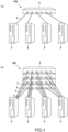
- a parallel and distributed computing system 100 of the present embodiment is obtained by interconnecting a plurality of computers 2 to each other via a data link 3 and a switching hub device 4.
- a parallel and distributed computing system may be configured by interconnecting a plurality of computers 2 via a plurality of data links 3 and a switching hub devices 4.
- each of the computers 2 includes a processor 21 including a translation lookaside buffer (TLB), a physical memory 22, and a network interface controller (NIC: network interface card) 23 directly accessible to the physical memory 22.
- processor 21 including a translation lookaside buffer (TLB), a physical memory 22, and a network interface controller (NIC: network interface card) 23 directly accessible to the physical memory 22.
- TLB translation lookaside buffer
- NIC network interface controller
- the parallel and distributed computing system 100 does not require any special communication and/or synchronization hardware but uses a stock network interface card (NIC) 23 to construct a memory-based communication facility (MBCF) to implement high-speed high-performance communication and/or synchronization by remote memory operations only by software.
- NIC stock network interface card
- the parallel and distributed computing system 100 constructs a memory-based communication facility (MBCF) by an operating system (OS) stored in a kernel space of each computer 2.
- OS operating system
- the parallel and distributed computing system 100 has variations of various operation commands such as a WRITE command (MBCF_WRITE) for performing remote memory writing and a READ command (MBCF_READ) for performing remote memory reading described below.
- a WRITE command (MBCF_WRITE) for performing remote memory writing
- a READ command (MBCF_READ) for performing remote memory reading described below.
- a process of a transmission source computer 2 (2X) transmits an operation request packet including an identifier of an operation target process (hereinafter, a reception-side process) that defines a process of a transmission destination computer 2 (2Y), an operation target address that defines a memory area of the reception-side process, a data size to be written, and a data sequence
- the transmission destination computer 2 receives the operation request packet and stores the data sequence in the memory area defined by the reception-side process and the operation target address (MBCF_WRITE).
- the transmission-side process transmits an operation request packet including an identifier of an operation target process (hereinafter, a reception-side process) that defines a process of the transmission destination computer 2 (2Y), an operation target address that defines a memory area of the reception-side process, a data size to be read, and a data storage area address of the transmission-side process, and the transmission destination computer 2 (2Y) receives the operation request packet, reads a data sequence from the memory area defined by the reception-side process and the operation target address, and returns the data sequence to the data storage area of the transmission-side process (MBCF_READ).
- a reception-side process that defines a process of the transmission destination computer 2 (2Y
- an operation target address that defines a memory area of the reception-side process
- a data size to be read a data storage area address of the transmission-side process
- the transmission destination computer 2 (2Y) receives the operation request packet, reads a data sequence from the memory area defined by the reception-side process and the operation target address, and returns the data sequence to
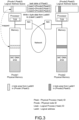
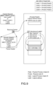
- FIG. 3 illustrates a use environment of MBCF_WRITE, in which Pnode1 is a transmission source node (transmission source computer) of the operation request packet, and Pnode2 is a reception-side node (transmission destination computer).
- the processor of the transmission source node creates a packet image including a header in which delivery information is written in a NIC DMA area of its own memory and a payload.
- the NIC DMA area memory can be directly accessed by the NIC for transmission or reception.
- the processor instructs the NIC to start a transmission operation by DMA reading (kick operation).
- the reception-side node has a ring buffer for packets arriving in the NIC DMA area of its own memory.
- the NIC of the reception-side node determines whether the packet is a packet addressed to its own node (normally, the determination is made by the MAC address), and generates a copy of the packet addressed to its own node in the ring buffer.
- the NIC then generates a hardware interrupt to inform the processor of the reception-side node of the arrival of the packet.
- parameters including an identifier [Ltask1] of the reception-side process (request destination task), an operation target address [Laddr1] of the reception-side process, an access key [AccessKey] for memory space operation of the reception-side process, a command type [MBCF_WRITE] of the MBCF, a data size [n] for performing remote writing, and a pointer [Laddr0] to the head of an area storing data to be written are prepared. Then, the MBCF request transmission system call is called with these parameters.
- the OS Upon receiving the system call, the OS refers to the task table of the transmission-side process and converts the logical task ID indicating the reception-side process into a physical task ID [(Pnode2, Ptask5)]. Since the physical task ID includes Pnode2 which is a physical node ID, route information (delivery destination information) to the reception-side node can be set from this information. If the network to be used is Ethernet, the MAC address is used as the delivery destination information. This delivery destination information enables the NIC to deliver the operation request packet to the reception-side node. Then, the OS causes the NIC to transmit the operation request packet.
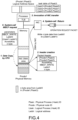
- FIG. 5 illustrates a situation in which the operation request packet arrives at the reception-side node.
- the operation request packet is carried by the network to the reception-side node [Pnode2].
- the NIC of the reception-side node copies the data image of the operation request packet to the ring buffer by DMA, and then generates an interrupt signal to inform the processor of the reception-side node that the packet has arrived.
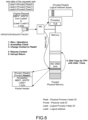
- FIG. 6 illustrates MBCF-related processing in the packet reception interrupt routine in the reception-side node. Due to the occurrence of the reception interrupt from the NIC, the control of the processor of the reception-side node is switched to the packet reception routine, and the low-level packet reception procedure required by the NIC is executed first. After the low-level reception procedure, in the packet reception routine, first, the reception-side process is specified from the physical task ID (Ptask5 in the drawing). Specifically, a pointer to a process structure of the process is obtained. Then, it is checked whether the AccessKey in the operation request packet matches that of the reception-side process, and only if there is a match, the memory operation in the memory space of the reception-side process is allowed.
- Ptask5 physical task ID
- the context of the memory space is switched to that of the reception-side process, and the n-byte data carried in the operation request packet is written from the logical address (Laddr1) by the store instruction of the user authority instead of as the privileged level. Then, the context of the memory space is returned to that at the time of occurrence of the interrupt. The processing in the interrupt routine is completed up to this point.
- MBCF_FIFO an operation of a transmission-side process (request side task) is almost the same as that of MBCF_WRITE.
- MBCF_WRITE of the command is replaced with MBCF_FIFO, and a destination indicated in the reception-side process (reception-side task) by the destination operation target address [Laddr1] is not an area for storing data but a FIFO structure in which a plurality of pointers defining a FIFO queue are stored. Therefore, description of the operation of the transmission-side process (request side task) of MBCF_FIFO will be omitted.
- FIG. 7 illustrates the status of the FIFO structure and FIFO queue in the reception-side process (request destination task) when an MBCF_FIFO operation request packet arrives at the request destination node (reception-side computer).
- Four pointers (four of top, head, tail, and bottom defining a ring buffer (buffer memory area)) and a state flag of the FIFO queue are stored in the FIFO structure (the state flag is omitted in the drawing).
- the processor reads the pointer and the flag in the FIFO structure to be operated, and stores the data carried in the packet in the buffer area defined by the pointer and the flag. Thereafter, the value of the pointer in the FIFO structure is updated.
- FIG. 1 illustrates the status of the FIFO structure and FIFO queue in the reception-side process (request destination task) when an MBCF_FIFO operation request packet arrives at the request destination node (reception-side computer).
- Four pointers four of top, head, tail, and bottom defining a
- FIG. 8 illustrates a situation after storing data in the FIFO queue and updating pointers in the FIFO structure.
- These memory operations in the request destination node are performed locally and inseparably. That is, since the operation is a node-local operation, an overhead cost is low, and it is ensured that other MBCF operation request packets do not access the FIFO structure of the same address during processing of the MBCF_FIFO operation request packet.
- a command (MBCF_WRITE_wLOG) in which the reception-side process records the operation history of the transmission-side process is implemented.
- the transmission-side process transmits an operation request packet (MBCF_WRITE_wLOG operation request packet) including an identifier of a reception-side process that defines a process of the transmission destination computer 2 (2Y), an operation target address that defines a memory area of the reception-side process, a data size to be written, a data sequence, and a structure address that defines a history memory area for temporarily recording an operation content history in the reception-side process.
- an operation request packet (MBCF_WRITE_wLOG operation request packet) including an identifier of a reception-side process that defines a process of the transmission destination computer 2 (2Y), an operation target address that defines a memory area of the reception-side process, a data size to be written, a data sequence, and a structure address that defines a history memory area for temporarily recording an operation content history in the reception-side process.
- the transmission destination computer 2 (2Y) receives the MBCF_WRITE_wLOG operation request packet and stores the data sequence in the memory area defined by the reception-side process and the operation target address. In addition, the transmission destination computer 2 (2Y) records the operation target address, the written data size, and the information of the transmission-side process in the history memory area as the operation content.
- the FIFO queue of the MBCF is used as the history memory area for temporarily recording the operation history.
- the operation of the FIFO queue is defined and implemented by MBCF_FIFO (described above) or MBCF_FIFO_READ.
- the content registered in the FIFO queue as the history memory area is not data loaded in the operation request packet, but the transmission destination computer 2 (2Y) registers write operation content such as the identifier of the transmission-side process, the operation target address, and the write data size regarding the MBCF_WRITE_wLOG operation packet.
- the transmission destination computer 2 (2Y) registers write operation content such as the identifier of the transmission-side process, the operation target address, and the write data size regarding the MBCF_WRITE_wLOG operation packet.
- FIG. 9 illustrates a state of the memory in the reception-side process (request destination task) when the MBCF_WRITE_wLOG operation request packet arrives at the request destination node (transmission destination computer).
- a data sequence carried in the operation request packet is stored by n bytes from the address of Laddr1, a FIFO structure at the address of Laddr2 defines a FIFO queue as a history memory area, and write operation content is registered in the FIFO queue.
- four pointers four of top, head, tail, and bottom defining a ring buffer (buffer memory area)
- a state flag of the FIFO queue are stored in the FIFO structure (the state flag is omitted in the drawing).
- the processor of the transmission destination computer 2 (2Y) reads the pointer and the flag in the FIFO structure as the operation target, and stores the operation target address (Laddr1), the written data size (n), and the information of the transmission-side process (Ltask4) in the buffer area (history memory area) defined by the pointer and the flag as the operation content (LOG DATA). Thereafter, the value of the pointer in the FIFO structure is updated. Note that, in a case where the FIFO queue overflows, if it is determined that there is no remote write, the operation content is registered in the FIFO queue first, and only in a case where the operation content has been registered, n-bytes data is written from the address of Laddr1.
- the transmission destination computer 2 (2Y) in which the reception-side process exists activates, to the reception-side process, an asynchronous user function that checks the content of the history memory area and performs a necessary operation at a time point when the operation content history is accumulated in the history memory area by a certain amount or more.
- the transmission destination computer 2 (2Y) is configured to save the data before being overwritten in the memory area of the reception-side process in the history memory area so that the reception-side process can perform rollback operations of remote writing and calculate various kinds of statistical calculations including summations at low cost.
- the address and size of the updated data are found from the history memory, it is possible to determine which row or which column needs to be recalculated from the information. Therefore, it is possible to limit the rows and columns to be recalculated to only where the update is made, and it is possible to significantly reduce the processing cost of the reception-side process.
- the sum of the rows and the columns can be calculated by subtracting the numerical value before the update from the sum before the recalculation and adding a new numerical value. Therefore, the sum of the rows and the columns can be obtained without even accessing the entire data of the rows or columns, and the average value can also be calculated.
- MBCF_TABLE tabular write command
- MBCF_TABLE_wLOG tabular write command
- These commands are remote write commands that do not directly specify a remote write address, but specify an area in which information defining a table in a reception-side process is stored as an operation target address, and specify a data storage location by information of a row and a column in the table.
- MBCF_TABLE is only different from MBCF_TABLE_wLOG in not leaving an operation history, and MBCF_TABLE_wLOG will be described below.
- a transmission-side process transmits an MBCF_TABLE_wLOG operation request packet including an identifier of a reception-side process that defines a process of a transmission destination computer 2 (2Y), an operation target address that defines a table area on a memory of the reception-side process, information of a row and a column in the table, a data size to be written, a data sequence, and a structure address that defines a history memory area for temporarily recording an operation content history in the reception-side process.
- the transmission destination computer 2 (2Y) receives the MBCF_TABLE_wLOG operation request packet, reads data from an area defining the table area specified by the reception-side process and the operation target address, obtains a memory address corresponding to the row and the column specified by the transmission-side process and stored in the operation request packet, and stores the data sequence from the address.
- the transmission destination computer 2 (2Y) records the operation target address, the information of the row and the column, the written data size, and the information of the transmission-side process in the history memory area as the operation content.
- the FIFO queue of the MBCF is used as the history memory area for temporarily recording the operation history.
- the operation of the FIFO queue is defined and implemented by MBCF_FIFO or MBCF_FIFO_READ described above.
- the content registered in the FIFO queue as the history memory area is not data loaded in the operation request packet, but the transmission destination computer 2 (2Y) registers the write operation content such as the identifier of the transmission-side process, the operation target address, and the write data size regarding the MBCF_TABLE_wLOG operation packet.
- the transmission destination computer 2 (2Y) registers the write operation content such as the identifier of the transmission-side process, the operation target address, and the write data size regarding the MBCF_TABLE_wLOG operation packet.
- FIG. 10 illustrates a state of the memory in the reception-side process (request destination task) when the MBCF_TABLE_wLOG operation request packet arrives at the request destination node (transmission destination computer).
- the data sequence carried in the operation request packet is stored by n bytes as the data of the cell of the specified row and column of the table memory area defined by the TABLE structure at the address of Laddr1, the FIFO structure at the address of Laddr2 defines the FIFO queue as the history memory area, and the write operation content is registered in the FIFO queue.
- the processor of the transmission destination computer 2 (2Y) reads the pointer and the flag in the FIFO structure as the operation target, and stores the operation target address (Laddr1), the information of the row (row1) and the column (coll), the written data size (n), and the information of the transmission-side process (Ltask4) in the buffer area (history memory area) defined by the pointer and the flag as the operation content (LOG DATA).
- the value of the pointer in the FIFO structure is updated. Note that, in a case where the FIFO queue overflows, if it is determined that there is no remote write, the operation content is registered in the FIFO queue first, and only in a case where the operation content has been registered, n-byte data is written to the table defined by the TABLE structure of the address of Laddr1. Since MBCF_TABLE_wLOG is a write command to the cell in the table, the content of the cell itself replaces the data in the request packet.
- the transmission destination computer 2 (2Y) in which the reception-side process exists activates, to the reception-side process, an asynchronous user function that checks the content of the history memory area and performs a necessary operation at a time point when the operation content history is accumulated in the history memory area by a certain amount or more.
- the transmission destination computer 2 (2Y) is configured to save the data before being overwritten in the memory area of the reception-side process in the history memory area so that the reception-side process can perform rollback operations of remote writing and calculate various kinds of statistical calculations including summations at low cost.
- the usefulness of leaving a log of the write operation in the history memory will be specifically described below. Assume that a large tabular data area exists in the reception-side process and the statistical data is calculated in the reception-side process. Assume that a numerical value is stored in each item of the table, and the reception-side process calculates a total sum and an average of columns and a total sum and an average of rows and stores them as statistical data in another area. In a situation where there is no write operation log, since the reception-side process does not know which data has been updated, it is necessary to recalculate the sum and the average for all columns and all rows.
- the row and column of the updated data are found from the history memory, it is possible to limit the rows and columns to be recalculated to only where the update is made, and it is possible to significantly reduce the processing cost of the reception-side process.
- the sum of the rows and the columns can be calculated by subtracting the numerical value before the update from the sum before the recalculation and adding a new numerical value. Therefore, the sum of the rows and the columns can be obtained without even accessing the entire data of the rows or columns, and the average value can also be calculated.
- the operation request packet transmitted by the transmission-side process to the reception-side process includes the structure address that defines the history memory area for temporarily recording the operation content history in the reception-side process, and the transmission destination computer receives the operation request packet and records the operation target address, the written data size, and the information of the transmission-side process in the history memory area as the operation content. Therefore, the reception-side process can recognize the content of the memory operation and perform necessary processing at low cost.
Landscapes
- Engineering & Computer Science (AREA)
- Theoretical Computer Science (AREA)
- Physics & Mathematics (AREA)
- General Engineering & Computer Science (AREA)
- General Physics & Mathematics (AREA)
- Mathematical Physics (AREA)
- Computer Hardware Design (AREA)
- Software Systems (AREA)
- Information Retrieval, Db Structures And Fs Structures Therefor (AREA)
Applications Claiming Priority (2)
| Application Number | Priority Date | Filing Date | Title |
|---|---|---|---|
| JP2020129496 | 2020-07-30 | ||
| PCT/JP2021/022269 WO2022024562A1 (ja) | 2020-07-30 | 2021-06-11 | 並列分散計算システム |
Publications (2)
| Publication Number | Publication Date |
|---|---|
| EP4170508A1 true EP4170508A1 (de) | 2023-04-26 |
| EP4170508A4 EP4170508A4 (de) | 2024-07-17 |
Family
ID=80035392
Family Applications (1)
| Application Number | Title | Priority Date | Filing Date |
|---|---|---|---|
| EP21848655.3A Pending EP4170508A4 (de) | 2020-07-30 | 2021-06-11 | Paralleles und verteiltes rechnersystem |
Country Status (4)
| Country | Link |
|---|---|
| US (1) | US20230315647A1 (de) |
| EP (1) | EP4170508A4 (de) |
| JP (1) | JP7645497B2 (de) |
| WO (1) | WO2022024562A1 (de) |
Family Cites Families (4)
| Publication number | Priority date | Publication date | Assignee | Title |
|---|---|---|---|---|
| JPH064363A (ja) * | 1992-06-22 | 1994-01-14 | Nec Corp | セッション状態ログ採取装置 |
| JP3120033B2 (ja) * | 1996-03-19 | 2000-12-25 | 株式会社東芝 | 分散メモリ型マルチプロセッサシステム及び故障回復方法 |
| US8868514B2 (en) * | 2011-01-07 | 2014-10-21 | Microsoft Corporation | Transaction support for distributed data |
| CN111831337B (zh) * | 2019-04-19 | 2022-11-29 | 安徽寒武纪信息科技有限公司 | 数据同步方法及装置以及相关产品 |
-
2021
- 2021-06-11 US US18/018,760 patent/US20230315647A1/en active Pending
- 2021-06-11 JP JP2022540050A patent/JP7645497B2/ja active Active
- 2021-06-11 EP EP21848655.3A patent/EP4170508A4/de active Pending
- 2021-06-11 WO PCT/JP2021/022269 patent/WO2022024562A1/ja not_active Ceased
Also Published As
| Publication number | Publication date |
|---|---|
| JPWO2022024562A1 (de) | 2022-02-03 |
| JP7645497B2 (ja) | 2025-03-14 |
| US20230315647A1 (en) | 2023-10-05 |
| WO2022024562A1 (ja) | 2022-02-03 |
| EP4170508A4 (de) | 2024-07-17 |
Similar Documents
| Publication | Publication Date | Title |
|---|---|---|
| US7870306B2 (en) | Shared memory message switch and cache | |
| EP0365731B1 (de) | Verfahren und Vorrichtung zur Nachrichtenübertragung zwischen Quellen- und Zielanwender durch einen anteilig genutzten Speicher | |
| US9935899B2 (en) | Server switch integration in a virtualized system | |
| EP1358562B8 (de) | Verfahren und vorrichtung zur steuerung des datenflusses zwischen datenverarbeitungssystemen über einen speicher | |
| US5682553A (en) | Host computer and network interface using a two-dimensional per-application list of application level free buffers | |
| US8588228B1 (en) | Nonvolatile memory controller with host controller interface for retrieving and dispatching nonvolatile memory commands in a distributed manner | |
| US8542693B2 (en) | Managing free packet descriptors in packet-based communications | |
| US7111092B1 (en) | Buffer management technique for a hypertransport data path protocol | |
| US7117308B1 (en) | Hypertransport data path protocol | |
| EP0651329A2 (de) | Rasterpufferung von Netzwerkdatenpaketen | |
| WO2002061593A1 (en) | Method and apparatus for controlling flow of data between data processing systems via a memory | |
| US20040054822A1 (en) | Transferring interrupts from a peripheral device to a host computer system | |
| US20240330216A1 (en) | Direct memory access system with read reassembly circuit | |
| US7895239B2 (en) | Queue arrays in network devices | |
| EP3077914A1 (de) | System und verfahren zur verwaltung und unterstützung eines virtuellen host-bus-adapters (vbha) über ein infiniband (ib) und zur unterstützung einer effizienten pufferausnutzung mit einer einzelnen externen speicherschnittstelle | |
| US9288163B2 (en) | Low-latency packet receive method for networking devices | |
| US7552232B2 (en) | Speculative method and system for rapid data communications | |
| US20080263171A1 (en) | Peripheral device that DMAS the same data to different locations in a computer | |
| US20200371708A1 (en) | Queueing Systems | |
| US7913059B2 (en) | Information processing device, data transfer method, and information storage medium | |
| US6601150B1 (en) | Memory management technique for maintaining packet order in a packet processing system | |
| TWI223747B (en) | Increasing memory access efficiency for packet applications | |
| EP4170508A1 (de) | Paralleles und verteiltes rechnersystem | |
| EP4155958B1 (de) | Paralleles und verteiltes rechnersystem | |
| US9338219B2 (en) | Direct push operations and gather operations |
Legal Events
| Date | Code | Title | Description |
|---|---|---|---|
| STAA | Information on the status of an ep patent application or granted ep patent |
Free format text: STATUS: THE INTERNATIONAL PUBLICATION HAS BEEN MADE |
|
| PUAI | Public reference made under article 153(3) epc to a published international application that has entered the european phase |
Free format text: ORIGINAL CODE: 0009012 |
|
| STAA | Information on the status of an ep patent application or granted ep patent |
Free format text: STATUS: REQUEST FOR EXAMINATION WAS MADE |
|
| 17P | Request for examination filed |
Effective date: 20230123 |
|
| AK | Designated contracting states |
Kind code of ref document: A1 Designated state(s): AL AT BE BG CH CY CZ DE DK EE ES FI FR GB GR HR HU IE IS IT LI LT LU LV MC MK MT NL NO PL PT RO RS SE SI SK SM TR |
|
| DAV | Request for validation of the european patent (deleted) | ||
| DAX | Request for extension of the european patent (deleted) | ||
| A4 | Supplementary search report drawn up and despatched |
Effective date: 20240619 |
|
| RIC1 | Information provided on ipc code assigned before grant |
Ipc: G06F 15/173 20060101AFI20240613BHEP |