EP4170387A1 - Radar detection method and related device - Google Patents
Radar detection method and related device Download PDFInfo
- Publication number
- EP4170387A1 EP4170387A1 EP20942849.9A EP20942849A EP4170387A1 EP 4170387 A1 EP4170387 A1 EP 4170387A1 EP 20942849 A EP20942849 A EP 20942849A EP 4170387 A1 EP4170387 A1 EP 4170387A1
- Authority
- EP
- European Patent Office
- Prior art keywords
- time domain
- slope
- signal
- beat frequency
- mus
- Prior art date
- Legal status (The legal status is an assumption and is not a legal conclusion. Google has not performed a legal analysis and makes no representation as to the accuracy of the status listed.)
- Pending
Links
Images







Classifications
-
- G—PHYSICS
- G01—MEASURING; TESTING
- G01S—RADIO DIRECTION-FINDING; RADIO NAVIGATION; DETERMINING DISTANCE OR VELOCITY BY USE OF RADIO WAVES; LOCATING OR PRESENCE-DETECTING BY USE OF THE REFLECTION OR RERADIATION OF RADIO WAVES; ANALOGOUS ARRANGEMENTS USING OTHER WAVES
- G01S17/00—Systems using the reflection or reradiation of electromagnetic waves other than radio waves, e.g. lidar systems
- G01S17/02—Systems using the reflection of electromagnetic waves other than radio waves
- G01S17/06—Systems determining position data of a target
- G01S17/08—Systems determining position data of a target for measuring distance only
-
- G—PHYSICS
- G01—MEASURING; TESTING
- G01S—RADIO DIRECTION-FINDING; RADIO NAVIGATION; DETERMINING DISTANCE OR VELOCITY BY USE OF RADIO WAVES; LOCATING OR PRESENCE-DETECTING BY USE OF THE REFLECTION OR RERADIATION OF RADIO WAVES; ANALOGOUS ARRANGEMENTS USING OTHER WAVES
- G01S17/00—Systems using the reflection or reradiation of electromagnetic waves other than radio waves, e.g. lidar systems
- G01S17/02—Systems using the reflection of electromagnetic waves other than radio waves
- G01S17/06—Systems determining position data of a target
- G01S17/42—Simultaneous measurement of distance and other co-ordinates
-
- G—PHYSICS
- G01—MEASURING; TESTING
- G01S—RADIO DIRECTION-FINDING; RADIO NAVIGATION; DETERMINING DISTANCE OR VELOCITY BY USE OF RADIO WAVES; LOCATING OR PRESENCE-DETECTING BY USE OF THE REFLECTION OR RERADIATION OF RADIO WAVES; ANALOGOUS ARRANGEMENTS USING OTHER WAVES
- G01S17/00—Systems using the reflection or reradiation of electromagnetic waves other than radio waves, e.g. lidar systems
- G01S17/88—Lidar systems specially adapted for specific applications
- G01S17/89—Lidar systems specially adapted for specific applications for mapping or imaging
- G01S17/894—Three-dimensional [3D] imaging with simultaneous measurement of time-of-flight at a two-dimensional [2D] array of receiver pixels, e.g. time-of-flight cameras or flash lidar
-
- G—PHYSICS
- G01—MEASURING; TESTING
- G01S—RADIO DIRECTION-FINDING; RADIO NAVIGATION; DETERMINING DISTANCE OR VELOCITY BY USE OF RADIO WAVES; LOCATING OR PRESENCE-DETECTING BY USE OF THE REFLECTION OR RERADIATION OF RADIO WAVES; ANALOGOUS ARRANGEMENTS USING OTHER WAVES
- G01S17/00—Systems using the reflection or reradiation of electromagnetic waves other than radio waves, e.g. lidar systems
- G01S17/02—Systems using the reflection of electromagnetic waves other than radio waves
- G01S17/06—Systems determining position data of a target
- G01S17/08—Systems determining position data of a target for measuring distance only
- G01S17/32—Systems determining position data of a target for measuring distance only using transmission of continuous waves, whether amplitude-, frequency-, or phase-modulated, or unmodulated
- G01S17/34—Systems determining position data of a target for measuring distance only using transmission of continuous waves, whether amplitude-, frequency-, or phase-modulated, or unmodulated using transmission of continuous, frequency-modulated waves while heterodyning the received signal, or a signal derived therefrom, with a locally-generated signal related to the contemporaneously transmitted signal
-
- G—PHYSICS
- G01—MEASURING; TESTING
- G01S—RADIO DIRECTION-FINDING; RADIO NAVIGATION; DETERMINING DISTANCE OR VELOCITY BY USE OF RADIO WAVES; LOCATING OR PRESENCE-DETECTING BY USE OF THE REFLECTION OR RERADIATION OF RADIO WAVES; ANALOGOUS ARRANGEMENTS USING OTHER WAVES
- G01S17/00—Systems using the reflection or reradiation of electromagnetic waves other than radio waves, e.g. lidar systems
- G01S17/02—Systems using the reflection of electromagnetic waves other than radio waves
- G01S17/50—Systems of measurement based on relative movement of target
- G01S17/58—Velocity or trajectory determination systems; Sense-of-movement determination systems
-
- G—PHYSICS
- G01—MEASURING; TESTING
- G01S—RADIO DIRECTION-FINDING; RADIO NAVIGATION; DETERMINING DISTANCE OR VELOCITY BY USE OF RADIO WAVES; LOCATING OR PRESENCE-DETECTING BY USE OF THE REFLECTION OR RERADIATION OF RADIO WAVES; ANALOGOUS ARRANGEMENTS USING OTHER WAVES
- G01S7/00—Details of systems according to groups G01S13/00, G01S15/00, G01S17/00
- G01S7/48—Details of systems according to groups G01S13/00, G01S15/00, G01S17/00 of systems according to group G01S17/00
- G01S7/4802—Details of systems according to groups G01S13/00, G01S15/00, G01S17/00 of systems according to group G01S17/00 using analysis of echo signal for target characterisation; Target signature; Target cross-section
-
- G—PHYSICS
- G01—MEASURING; TESTING
- G01S—RADIO DIRECTION-FINDING; RADIO NAVIGATION; DETERMINING DISTANCE OR VELOCITY BY USE OF RADIO WAVES; LOCATING OR PRESENCE-DETECTING BY USE OF THE REFLECTION OR RERADIATION OF RADIO WAVES; ANALOGOUS ARRANGEMENTS USING OTHER WAVES
- G01S7/00—Details of systems according to groups G01S13/00, G01S15/00, G01S17/00
- G01S7/48—Details of systems according to groups G01S13/00, G01S15/00, G01S17/00 of systems according to group G01S17/00
- G01S7/481—Constructional features, e.g. arrangements of optical elements
- G01S7/4817—Constructional features, e.g. arrangements of optical elements relating to scanning
-
- G—PHYSICS
- G01—MEASURING; TESTING
- G01S—RADIO DIRECTION-FINDING; RADIO NAVIGATION; DETERMINING DISTANCE OR VELOCITY BY USE OF RADIO WAVES; LOCATING OR PRESENCE-DETECTING BY USE OF THE REFLECTION OR RERADIATION OF RADIO WAVES; ANALOGOUS ARRANGEMENTS USING OTHER WAVES
- G01S7/00—Details of systems according to groups G01S13/00, G01S15/00, G01S17/00
- G01S7/48—Details of systems according to groups G01S13/00, G01S15/00, G01S17/00 of systems according to group G01S17/00
- G01S7/491—Details of non-pulse systems
- G01S7/493—Extracting wanted echo signals
-
- G—PHYSICS
- G01—MEASURING; TESTING
- G01S—RADIO DIRECTION-FINDING; RADIO NAVIGATION; DETERMINING DISTANCE OR VELOCITY BY USE OF RADIO WAVES; LOCATING OR PRESENCE-DETECTING BY USE OF THE REFLECTION OR RERADIATION OF RADIO WAVES; ANALOGOUS ARRANGEMENTS USING OTHER WAVES
- G01S13/00—Systems using the reflection or reradiation of radio waves, e.g. radar systems; Analogous systems using reflection or reradiation of waves whose nature or wavelength is irrelevant or unspecified
- G01S13/02—Systems using reflection of radio waves, e.g. primary radar systems; Analogous systems
- G01S13/06—Systems determining position data of a target
- G01S13/08—Systems for measuring distance only
- G01S13/32—Systems for measuring distance only using transmission of continuous waves, whether amplitude-, frequency-, or phase-modulated, or unmodulated
- G01S13/34—Systems for measuring distance only using transmission of continuous waves, whether amplitude-, frequency-, or phase-modulated, or unmodulated using transmission of continuous, frequency-modulated waves while heterodyning the received signal, or a signal derived therefrom, with a locally-generated signal related to the contemporaneously transmitted signal
- G01S13/345—Systems for measuring distance only using transmission of continuous waves, whether amplitude-, frequency-, or phase-modulated, or unmodulated using transmission of continuous, frequency-modulated waves while heterodyning the received signal, or a signal derived therefrom, with a locally-generated signal related to the contemporaneously transmitted signal using triangular modulation
-
- G—PHYSICS
- G01—MEASURING; TESTING
- G01S—RADIO DIRECTION-FINDING; RADIO NAVIGATION; DETERMINING DISTANCE OR VELOCITY BY USE OF RADIO WAVES; LOCATING OR PRESENCE-DETECTING BY USE OF THE REFLECTION OR RERADIATION OF RADIO WAVES; ANALOGOUS ARRANGEMENTS USING OTHER WAVES
- G01S7/00—Details of systems according to groups G01S13/00, G01S15/00, G01S17/00
- G01S7/02—Details of systems according to groups G01S13/00, G01S15/00, G01S17/00 of systems according to group G01S13/00
- G01S7/35—Details of non-pulse systems
- G01S7/352—Receivers
- G01S7/354—Extracting wanted echo-signals
Definitions
- This application relates to the field of lidar technologies, and in particular, to a radar detection method and a related apparatus.
- a frequency modulated continuous wave (frequency modulated continuous wave, FMCW) radar is a ranging device, which includes different subdivided types.
- a frequency modulated continuous wave radar using radio waves is referred to as an FMCW radar
- a frequency modulated continuous wave radar using laser lights is referred to as an FMCW lidar.
- An FMCW radar of any type includes a structure shown in FIG. 1 . In FIG. 1 , the radar generates a radio frequency or laser signal on which frequency modulation is performed, and divides the generated frequency modulated signal into two channels.
- One channel is used as a local reference signal (also referred to as a local oscillator signal), and the other channel is emitted to a detected target object (also referred to as a reflective object) and reflected by a surface of the target object to form an echo signal.
- a local reference signal also referred to as a local oscillator signal
- the other channel is emitted to a detected target object (also referred to as a reflective object) and reflected by a surface of the target object to form an echo signal.
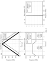
- FIG. 2 shows reference and echo signal processing by an FMCW radar.
- a thick line indicates that frequencies of the transmitted signal and the reference signal as frequency modulated signals change over time. In the first half of time, the signal frequency increases over time, and in the second half of the time, the signal frequency decreases over time.
- a fine line shows a changing process of the echo signal frequency.
- a beat frequency signal may be output after the echo signal and the reference signal are processed through a frequency mixer.
- a frequency of the beat frequency signal is a frequency difference between the reference signal frequency and the echo signal frequency, as shown in (b) in FIG. 2 . In an ideal condition, the beat frequency signal has a fixed frequency (as shown by a dashed-line part in the figure).
- the frequency of the beat frequency signal may be detected by performing frequency domain analysis (usually FFT) on the beat frequency signal.
- the frequency herein is in a one-to-one correspondence with a distance to and a speed of the target object. Therefore, speed and distance information of the target object may be calculated based on the frequency of the beat frequency signal.
- FIG. 3 there is usually a scanner in the lidar.
- the scanner emits laser lights in different directions by rotating the laser, and then gathers measurement results in all directions to obtain a 3D point cloud map.
- FIG. 4 shows a 3D point cloud map of the lidar.
- a point cloud resolution of the lidar is an important indicator.
- a high-resolution point cloud is very important for a machine vision algorithm used for autonomous driving, and is critical to implementation of functions such as point cloud segmentation and target identification.
- a point cloud resolution also referred to as a point cloud density or a point output rate
- a common method for improving the point cloud resolution is to add more lasers to a lidar, for example, upgrading a 32-line lidar (that is, 32 lasers work at the same time) to a 128-line lidar (that is, there are 128 lasers or 128 lasers are simulated by optical components).
- Embodiments of this application disclose a radar detection method and a related apparatus, so that a point output rate (that is, a point cloud density) of a radar can be improved without lowering a signal-to-noise ratio or increasing costs significantly.
- an embodiment of this application discloses a radar detection method, and the method includes:
- measurement units MUs are intercepted from the beat frequency signal in a manner of sliding window, and because a time domain length of the time domain sliding step is less than the time domain length of each intercepted MU, any two adjacent MUs in time domain share a part of frequency information. Therefore, even if a large quantity of MUs are intercepted, it can still be ensured that sufficient signal energy is accumulated in each MU, to ensure a signal-to-noise ratio. Therefore, in this manner, the point output rate (that is, the point cloud density) can be improved without lowering the signal-to-noise ratio or increasing costs significantly.
- signal energy accumulated within a time domain length of a first MU in the plurality of MUs can ensure that a signal-to-noise ratio of the first MU is higher than a preset threshold.
- the beat frequency signal of the radar includes a first slope beat frequency signal obtained by a first laser transceiver and a second slope beat frequency signal obtained by a second laser transceiver.
- the intercepting a plurality of measurement units MUs from a beat frequency signal of a radar based on a time domain sliding step includes:
- the first slope is a positive slope
- the second slope is a negative slope
- the first slope is a positive slope or a negative slope
- the second slope is a zero slope
- two laser transmitters synchronously transmit laser lights, so that beat frequency signals with two different slopes can be synchronously obtained, and this shortens a time for obtaining beat frequency signals with two slopes, and improves a speed of calculating a point cloud result in radar detection.
- the beat frequency signal of the radar includes a positive slope beat frequency signal and a negative slope beat frequency signal that are alternately obtained by a third laser transceiver in time domain, and each of the plurality of measurement units includes a positive slope part and a negative slope part.
- an embodiment of this application provides a signal processing apparatus.
- the apparatus includes:
- measurement units MUs are intercepted from the beat frequency signal in a manner of sliding window, and because a time domain length of the time domain sliding step is less than the time domain length of each intercepted MU, any two adjacent MUs in time domain share a part of frequency information. Therefore, even if a large quantity of MUs are intercepted, it can still be ensured that sufficient signal energy is accumulated in each MU, and to ensure a signal-to-noise ratio. Therefore, in this manner, the point output rate (that is, the point cloud density) can be improved without lowering a signal-to-noise ratio or increasing costs significantly.
- signal energy accumulated within a time domain length of a first MU in the plurality of MUs can ensure that a signal-to-noise ratio of the first MU is higher than a preset threshold.
- the beat frequency signal of the radar includes a first slope beat frequency signal obtained by a first laser transceiver and a second slope beat frequency signal obtained by a second laser transceiver.
- the first slope is a positive slope
- the second slope is a negative slope
- the first slope is a positive slope or a negative slope
- the second slope is a zero slope
- two laser transmitters synchronously transmit laser lights, so that beat frequency signals with two different slopes can be synchronously obtained, and this shortens a time for obtaining beat frequency signals with two slopes, and improves a speed of calculating a point cloud result in radar detection.
- the beat frequency signal of the radar includes a positive slope beat frequency signal and a negative slope beat frequency signal that are alternately obtained by a third laser transceiver in time domain, and each of the plurality of measurement units MUs includes a positive slope part and a negative slope part.
- an embodiment of this application provides a processor.
- the processor is configured to invoke a computer program stored in a computer-readable storage medium, to implement the method described in any one of the first aspect or a possible implementation of the first aspect.
- an embodiment of this application provides a lidar system.
- the lidar system includes a processor, a memory, and a laser.
- the laser is configured to transmit a laser signal.
- the memory is configured to store a computer program.
- the processor is configured to invoke the computer program to implement the method described in any one of the first aspect or a possible implementation of the first aspect.
- an embodiment of this application provides a computer-readable storage medium.
- the computer-readable storage medium stores a computer program, and when the computer program is run on a processor, the method described in any one of the first aspect or a possible implementation of the first aspect is implemented.
- a lidar in embodiments of this application can be applied to various fields such as intelligent transportation, autonomous driving, atmospheric environment monitoring, geographic surveying and mapping, and uncrewed aerial vehicle, and can complete functions such as distance measurement, speed measurement, target tracking, and imaging recognition.
- FIG. 5 is a schematic diagram of a structure of a lidar system according to an embodiment of this application.
- the lidar system is configured to detect information about a target object 505.
- the lidar system includes:
- the target object 505 is also referred to as a reflective object.
- the target object 505 may be any object in a scanning direction of the scanner 504, for example, may be a person, a mountain, a vehicle, a tree, or a bridge.
- FIG. 5 uses a vehicle as an example for illustration.
- an operation of processing a beat frequency signal obtained through sampling to obtain information such as a speed and a distance of the target object may be completed by one or more processors 512, for example, by one or more DSPs, or may be completed by one or more processors 512 in combination with another component, for example, a DSP in combination with one or more central processing units CPUs.
- the processor 512 may specifically invoke a computer program stored in a computer-readable storage medium.
- the computer-readable storage medium includes but is not limited to a random access memory (random access memory, RAM), a read-only memory (read-only memory, ROM), an erasable programmable read-only memory (erasable programmable read-only memory, EPROM) or a portable read-only memory (compact disc read-only memory, CD-ROM).
- RAM random access memory
- ROM read-only memory
- EPROM erasable programmable read-only memory
- portable read-only memory compact disc read-only memory
- the laser 501 may alternately transmit a laser signal with a positive slope and a laser signal with a negative slope in time domain.
- one laser 501 transmits a laser signal with a positive slope
- the other laser 501 transmits a laser signal with a negative slope
- the two lasers 501 may synchronously transmit laser signals.
- a modulation waveform of a laser signal frequency is triangle wave linear frequency modulation.
- an echo signal is mixed with a local oscillator signal LO.
- This period of time of flight is a period of time from a moment when a transmitted signal divided from a laser signal starts to be emitted to a moment when the echo signal returns.
- the echo signal and a beat frequency signal generated by the local oscillator signal are constant in a certain period of time, and can accurately reflect distance information and speed information of a target object.
- This period of time is a beat frequency time.
- the beat frequency signal needs to include a beat frequency f 1 corresponding to a positive slope and a beat frequency f 2 corresponding to a negative slope.
- a coherent lidar needs to increase a beat frequency time of each measurement unit (Measurement Unit, MU) (one measurement unit MU is used to obtain a detection result of one measurement point), to accumulate more energy in a process of processing the beat frequency signal, so as to achieve a higher signal-to-noise ratio.
- the lidar is required to have a higher point output rate, so that the lidar obtains a higher field-of-view resolution and frame rate.
- a common linear frequency modulation coherent signal processing method for saw wave is shown in FIG. 7 .
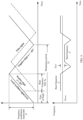
- a period of time remaining after a time of flight corresponding to a farthest detection distance is subtracted from a modulation period T is used as a beat frequency time TB, data in the beat frequency time TB is collected, Fourier transform is performed on the data to obtain a frequency of a real-time beat frequency signal, and then a distance of the target object is calculated based on the frequency.
- a measurement time TM of each measurement point is less than or equal to TB. Further, if other measurement channels with different linear frequency modulation slopes are used in combination, a speed of the target object can be obtained.
- a plurality of measurement units MUs may be divided in a single beat frequency time. As shown in FIG. 8 , a beat frequency time is divided into three segments, to obtain three MUs (corresponding to three measurement points), and one detection may be completed based on a signal of each MU. In this way, the point output rate is three times an original point output rate, and the beat frequency time of each measurement unit MU is 1/3 of an original beat frequency time.
- a common linear frequency modulation coherent signal processing method for triangle wave is shown in FIG. 9 .
- a time of flight and a beat frequency time are respectively divided in a positive slope modulation period and a negative slope modulation period.
- a signal processing manner in each beat frequency time is the same as the linear frequency modulation coherent signal processing method for saw wave.
- a beat frequency f 1 is obtained through processing
- a beat frequency f 2 is obtained through processing, so that distance information and speed information of a target can be obtained with one measurement channel.
- a beat frequency time in a positive slope period and a negative slope period may be divided into a plurality of measurement times.
- a beat frequency time T ⁇ in a negative slope period are divided into three measurement times T 0 respectively corresponding to three measurement units MUs. Based on each measurement unit MU, one detection can be completed. Therefore, the point output rate is three times an original point output rate, and the beat frequency time of each measurement unit MU is 1/3 of an original beat frequency time.
- an embodiment of this application provides the method shown in FIG. 11 .
- FIG. 11 shows a radar detection method according to an embodiment of this application.
- the method may be implemented based on components in the lidar system shown in FIG. 5 .
- Some operations in subsequent descriptions are completed by a signal processing apparatus, and the signal processing apparatus may be the foregoing processor 512, or an apparatus in which the foregoing processor 512 is deployed, for example, a lidar system in which the foregoing processor 512 is deployed or a module in the lidar system.
- the method includes but is not limited to the following steps:
- Step S1101 A signal processing apparatus intercepts a plurality of MUs from a beat frequency signal of a radar based on a time domain sliding step.
- a time domain length of each measurement unit (Measurement Unit, MU) in the plurality of intercepted MLTs is greater than a time domain length of the time domain sliding step.
- Each measurement unit MU herein is used as a measurement signal of a measurement point. Because the time domain length of each MU in the plurality of intercepted MUs is greater than the time domain length of the time domain sliding step, some beat frequency signals are repeated between any two MUs that are adjacent in time domain. This improves utilization of the beat frequency signals to a maximum extent, enhances energy of a signal in a single MU, and improves a signal-to-noise ratio.
- FIG. 12 shows a method for processing a linear frequency modulation coherent lidar signal modulated based on a saw wave.
- a scanner 504 drives a transmitted signal to deflect, so that a beam of the transmitted signal (also referred to as a laser signal) moves on surfaces of different target objects. Therefore, the target object represented by a reflected echo signal also changes with a deflection angle of the scanner 504.
- a beat frequency signal formed by the echo signal reflected by the target object and a local oscillator signal LO may be respectively represented as follows:
- a beat frequency signal formed by an echo signal reflected by a target object and the local oscillator signal LO is: ⁇ D2 + k ⁇ ⁇ 2 , where ⁇ 2 is a time from a moment when a laser light is emitted to a moment when the echo signal of the target 2 is reflected back to the lidar, and ⁇ D2 is a frequency shift of the beat frequency signal due to a speed of the target 2.
- a beat frequency signal formed by an echo signal reflected by a target 3 and the local oscillator signal LO is: ⁇ D3 + k ⁇ ⁇ 3 , where ⁇ 3 is a time from a moment when a laser light is emitted to a moment when the echo signal of the target 3 is reflected back to the lidar, and ⁇ D3 is a frequency shift of the beat frequency signal due to a speed of the target 3.
- each measurement unit MU can output a group of information such as distance, speed, and amplitude.
- a spacing between an interception start moment of a latter measurement unit and an interception start moment of a previous measurement unit is ⁇ , and ⁇ ⁇ T M .
- ⁇ is a time domain sliding step mentioned above.
- signal energy accumulated in a time domain length T M of a first MU can ensure that a signal-to-noise ratio of the first MU is higher than a preset threshold, where the first MU is any intercepted MU.
- the T M is not randomly selected, and is mainly selected based on a signal-to-noise ratio requirement for effectively extracting information by using a data processing method. For example, if a beat frequency is extracted by using Fourier transform, a T M is longer, more energy is accumulated in a target beat frequency, and a signal-to-noise ratio is higher. Therefore, a time domain length T M of any MU needs to be greater than a specific length, and cannot be randomly selected.
- time domain lengths of the plurality of intercepted MUs are the same.
- a time domain length of the second MU is the same as a time domain length of the third MU.
- time domain lengths of the plurality of intercepted MUs are not completely the same.
- a time domain length of the second MU may be different from a time domain length of the third MU.
- a structure of a lidar for transmitting and receiving signals may be set according to a requirement.
- the following two structures are used as examples in this embodiment of this application, and how to specifically intercept MUs for the two different structures is described.
- FIG. 13 shows a dual-channel lidar system.
- a structure shown in FIG. 13 may be considered as obtained by adding corresponding components based on the system shown in FIG. 5 .
- some components in FIG. 5 are doubled in quantity in FIG. 13 , such as the detector and the splitter.
- the structure shown in FIG. 13 includes an ADC, a first laser transceiver, a second laser transceiver, a beam combiner, a collimator, a scanner, and a target object.
- the first laser transceiver includes a laser 1, a splitter 1, a frequency mixer 1, a receiving lens 1, and a detector 1.
- the second laser transceiver includes a laser 2, a splitter 2, a frequency mixer 2, a receiving lens 2, and a detector 2.
- a signal processing procedure is as follows:
- the laser 1 is used for modulation of a first slope.
- a laser signal generated by the laser 1 is split by the splitter 1 to obtain a local oscillator signal LO1 and a transmitted signal.
- the laser 2 is used for modulation of a second slope.
- the laser signal generated by the laser 2 is split by the splitter 2 to obtain a local oscillator signal LO2 and a transmitted signal.
- signal receiving and sending of the first laser transceiver and signal receiving and sending of the second laser transceiver are synchronous.
- the transmitted signals obtained through splitting by the splitter 1 and the splitter 2 are combined at the beam combiner, and then transmitted to the scanner through the collimator.
- the scanner transmits the transmitted signals to the target object at a certain angle.
- the target object reflects an echo to the scanner to form an echo signal.
- One part of the echo signal that is, an echo signal 1 passes through the receiving lens 1 and arrives at the frequency mixer 1
- the other part of the echo signal that is, an echo signal 2
- the frequency mixer 1 mixes the echo signal 1 and the local oscillator signal LO1 to obtain a beat frequency signal 1, and the obtained beat frequency signal 1 is a first slope beat signal.
- the frequency mixer 2 mixes the echo signal 2 and the local oscillator signal LO2 to obtain a beat frequency signal 2, and the obtained beat frequency signal 2 is a second slope beat signal.
- the detector 1 correspondingly collects the beat frequency signal 1, and the detector 2 correspondingly collects the beat frequency signal 2.
- a beat frequency shift that is generated due to a distance and that is of a target 1 is ⁇ 1
- a beat frequency shift that is generated due to a speed and that is of the target 1 is ⁇ D1
- the beat frequency signal 1 that is collected by the detector 1 and that is of the target 1 is ⁇ D1 + ⁇ 1
- the beat frequency signal 2 that is collected by the detector 2 and that is of the target 1 is - ⁇ D1 + ⁇ 1 .
- a beat frequency shift that is generated due to a distance and that is of a target 2 is ⁇ 2
- a beat frequency shift that is generated due to a speed and that is of the target 2 is ⁇ D2
- the beat frequency signal 1 that is collected by the detector 1 and that is of the target 1 is ⁇ D2 + ⁇ 2
- the beat frequency signal 2 that is collected by the detector 2 and that is of the target 1 is - ⁇ D2 + ⁇ 2 .
- a case of a beat frequency signal corresponding to a target 3 is deduced by analogy, and details are not described herein.
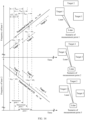
- the intercepting a plurality of measurement units MUs from a beat signal of a radar based on a time domain sliding step may be specifically: intercepting a plurality of first measurement units MUs from the first slope beat frequency signal based on the time domain sliding step, and synchronously intercepting a plurality of second measurement units MUs from the second slope beat frequency signal based on the time domain sliding step, where one MU includes one first MU and one second MU, and the first MU is synchronized with the second MU in time domain. It may be understood that, based on a time domain sequence, a time domain of an i th first measurement unit MU is synchronized with a time domain of an i th second measurement unit, where i is a positive integer.
- a beat frequency signal obtained in a time domain T M1 may be referred to as a measurement unit 1
- a beat frequency signal obtained in a time domain T M2 may be referred to as a measurement unit 2
- a beat frequency signal obtained in a time domain T M3 may be referred to as a measurement unit 3.
- a time-domain deviation between a start point of T M1 and a start point of T M2 is ⁇ T 1
- a time-domain deviation between the start point of T M2 and a start point of T M3 is ⁇ T 2 .
- Both ⁇ T 1 and ⁇ T 2 may be considered as the foregoing time domain sliding step, and both ⁇ T 1 and ⁇ T 2 are less than a time domain length of T M1 , a time domain length of T M2 , and a time domain length of T M3 .
- the measurement unit 1 actually includes a first measurement unit MU and a second measurement unit MU, and the measurement unit 1 is configured to serve as a measurement signal of the measurement point 1.
- the measurement unit 2 actually includes a first measurement unit MU and a second measurement unit MU, and the measurement unit 2 is configured to serve as a measurement signal of the measurement point 2.
- the measurement unit 3 also includes a first measurement unit MU and a second measurement unit MU, and the measurement unit 3 is configured to serve as a measurement signal of the measurement point 3.
- Two rows of beat frequency signals detected by the detector 1 and the detector 2 are collected (or sampled, usually a digital signal is sampled from an analog signal) and processed synchronously by the ADC, and two signals whose time domain lengths are T M1 after time of flight are used as measurement signals of the measurement point 1.
- a moment ⁇ T 1 after the start time of the measurement point 1 is used as a start point, and two signals whose time domain lengths are T M2 are used as measurement signals of the measurement point 2.
- a moment ⁇ T 2 after the start time of the measurement point 2 is used as a start point, and two signals whose time domain lengths are T M3 are used as measurement signals of the measurement point 3.
- time domain lengths of measurement units MUs such as T M1 , T M2 , and T M3
- time domain sliding steps such as ⁇ T 1 and ⁇ T 2
- One of the criteria for determining the time domain length is the signal-to-noise ratio of the measurement unit MU obtained after interception.
- a threshold may be set. Only when a ratio of a power spectrum amplitude of a frequency component to an average power of a surrounding noise in a certain period of time is higher than this threshold, the frequency component is determined as a useful signal frequency, and then a frequency domain signal in this period of time is intercepted as a measurement unit MU.
- a useful signal frequency including information such as a distance of a target and a speed of the target may be distinguished.
- a longer time domain of each measurement unit indicates a higher spectrum amplitude of a useful signal included in the measurement unit, and this is more conducive to accurately extracting a spectrum peak value, and further improves detection accuracy of coherent measurement.
- the first slope is a positive slope
- the second slope is a negative slope
- the first slope is a positive slope or a negative slope
- the second slope is a zero slope
- FIG. 16 shows a single-channel lidar system.
- a structure of the single-channel lidar system has one less laser transceiver than the structure shown in FIG. 13 .
- the structure shown in FIG. 16 includes a laser transceiver, which is represented as a third laser transceiver.
- the third laser transceiver includes a laser, a detector, a frequency mixer, a splitter, and a receiving lens.
- the structure shown in FIG. 16 has one more receiving lens.
- the receiving lens is disposed between the scanner and the BPD.
- the laser may emit triangle wave linear frequency modulation laser light.
- a first half period of the triangle wave linear frequency modulation laser light is positive slope modulation, and a second half period is negative slope modulation, so that a frequency signal with a positive slope and a frequency signal with a negative slope are obtained.
- the detector may subsequently collect a positive slope beat signal and a negative slope beat signal alternately in time domain.
- each of the plurality of measurement units MUs intercepted based on the time domain sliding step includes a positive slope part and a negative slope part.
- a beat frequency signal obtained in a time domain T M1 may be referred to as a measurement unit 1
- a beat frequency signal obtained in a time domain T M2 may be referred to as a measurement unit 2
- a beat frequency signal obtained in a time domain T M3 may be referred to as a measurement unit 3.
- a time-domain deviation between a start point of T M1 and a start point of T M2 is ⁇ T 1
- a time-domain deviation between the start point of T M2 and a start point of T M3 is ⁇ T 2 .
- Both ⁇ T 1 and ⁇ T 2 may be considered as the foregoing time domain sliding step, and both ⁇ T 1 and ⁇ T 2 are less than a time domain length of T M1 , a time domain length of T M2 , and a time domain length of T M3 .
- the measurement unit 1 actually includes a positive slope beat frequency signal and a negative slope beat frequency signal that are staggered in time domain, and the measurement unit 1 is configured to serve as a measurement signal of the measurement point 1.
- the measurement unit 2 actually includes a positive slope beat frequency signal and a negative slope beat frequency signal that are staggered in time domain, and the measurement unit 2 is configured to serve as a measurement signal of the measurement point 2.
- the measurement unit 3 actually includes a positive slope beat frequency signal and a negative slope beat frequency signal that are staggered in time domain, and the measurement unit 3 is configured to serve as a measurement signal of the measurement point 3.
- the beat frequency signals detected by the detector are collected and processed synchronously by the ADC, and a signal whose time domain length is T M1 after time of flight is used as a measurement signal of the measurement point 1.
- a moment ⁇ T 1 after the start time of the measurement point 1 is used as a start point, and a signal whose time domain length is T M2 is used as a measurement signal of the measurement point 2.
- a moment ⁇ T 2 after the start time of the measurement point 2 is used as a start point, and a signal whose time domain length is T M3 is used as a measurement signal of the measurement point 3.
- time domain lengths of measurement units MUs such as T M1 , T M2 , and T M3
- time domain sliding steps such as ⁇ T 1 and ⁇ T 2
- One of the criteria for determining the time domain length is the signal-to-noise ratio of the measurement unit MU obtained after interception.
- a threshold may be set. Only when a ratio of a power spectrum amplitude of a frequency component to an average power of a surrounding noise in a certain period of time is higher than this threshold, the frequency component is determined as a useful signal frequency, and then a frequency domain signal in this period of time is intercepted as a measurement unit MU.
- a time domain length TM of each measurement unit should be greater than a triangle wave modulation period, and an interval between time domain starting moments of the measurement units should be less than the triangle wave modulation period.
- a useful signal frequency including information such as a distance of a target and a speed of the target may be distinguished.
- a longer time domain of each measurement unit indicates a higher spectrum amplitude of a useful signal included in the measurement unit, and this is more conducive to accurately extracting a spectrum peak value, and further improves detection accuracy of coherent measurement.
- Step S1102 The signal processing apparatus determines frequency information of each MU.
- frequency information in an MU may be extracted by performing Fourier transform on the MU, and frequency information of each MU may be extracted by performing Fourier transform on each of the plurality of MLTs.
- frequency information of each MU may also be extracted in another manner.
- Step S1103 The signal processing apparatus obtains a radar point cloud detection result based on the frequency information of each MU.
- a detection result of one detection point may be obtained based on frequency information of one MU, and one detection point corresponds to one point cloud. Therefore, it may be expressed that one radar point cloud detection result is obtained based on frequency information of one MU.
- the detection result includes one or more of a speed of the target object or a distance of the target object.
- a frequency change f speed due to a speed of the target object may be obtained for a second measurement unit intercepted for a beat frequency signal with a zero slope
- a frequency change f distance due to a distance of the target object may be obtained for the second measurement unit intercepted for the beat frequency signal with the zero slope and a first measurement unit intercepted for a beat frequency signal with a positive slope or a negative slope. Therefore, the speed and the distance of the target object may be separately obtained based on f speed and f distance .
- a power spectrum density function is implemented for a positive slope measurement unit of each measurement unit, to extract a spectral line higher than a preset signal-to-noise ratio threshold to serve as a useful frequency signal f 1 ; and the power spectrum density function is implemented for a negative slope measurement unit of each measurement unit, to extract a spectral line higher than a preset signal-to-noise ratio threshold to serve as a useful frequency signal f 2 .
- the power spectrum density function is implemented for a positive slope part (that is, a beat frequency signal within a half-period beat frequency time of the positive slope) of each measurement unit to extract a spectral line higher than a preset signal-to-noise ratio threshold to serve as a useful frequency signal f 1 ; and the power spectrum density function is implemented for a negative slope part (that is, a beat frequency signal within a half-period beat frequency time of the negative slope) of each measurement unit to extract a spectral line higher than a preset signal-to-noise ratio threshold to serve as a useful frequency signal f 2 .
- a moving speed of the target object is obtained through calculation based on f speed
- a distance between the target object (and the lidar) is obtained through calculation based on f distance .
- each intercepted measurement unit MU for each intercepted measurement unit MU, one detection result may be obtained by performing step S1103. Therefore, after the same step is performed on each intercepted measurement unit MU, a plurality of detection results may be obtained.
- measurement units MUs are intercepted from the beat frequency signal in a manner of sliding window, and because a time domain length of the time domain sliding step is less than the time domain length of each intercepted MU, any two adjacent MUs in time domain share a part of frequency information. Therefore, even if a large quantity of MUs are intercepted, it can still be ensured that sufficient signal energy is accumulated in each MU, to ensure a signal-to-noise ratio. Therefore, in this manner, the point output rate (that is, the point cloud density) can be improved without lowering the signal-to-noise ratio or increasing costs significantly.
- FIG. 18 is a schematic diagram of a structure of a signal processing apparatus 180 according to an embodiment of this application.
- the apparatus may be the foregoing lidar system, or a processor in the lidar system, or a related component used to deploy the processor in the lidar system.
- the signal processing apparatus 180 may include an interception unit 1801, a determining unit 1802, and an analysis unit 1803. The following describes the units in details.
- the interception unit 1801 is configured to intercept a plurality of measurement units MUs from a beat frequency signal of a radar based on a time domain sliding step, where a time domain length of each of the plurality of MUs is greater than a time domain length of a preset sliding step.
- the determining unit 1802 is configured to determine frequency information of each MU.
- the analysis unit 1803 is configured to obtain a radar point cloud detection result based on the frequency information of each MU, where the detection result includes at least one of a speed of a target object or a distance of the target object.
- measurement units MUs are intercepted from the beat frequency signal in a manner of sliding window, and because a time domain length of the time domain sliding step is less than the time domain length of each intercepted MU, any two adjacent MUs in time domain share a part of frequency information. Therefore, even if a large quantity of MUs are intercepted, it can still be ensured that sufficient signal energy is accumulated in each MU, to ensure a signal-to-noise ratio. Therefore, in this manner, the point output rate (that is, the point cloud density) can be improved without lowering the signal-to-noise ratio or increasing costs significantly.
- signal energy accumulated within a time domain length of a first MU in the plurality of MUs can ensure that a signal-to-noise ratio of the first MU is higher than a preset threshold.
- a time domain length of a second MU in the plurality of MUs is the same as a time domain length of a third MU in the plurality of MUs, or a time domain length of a second MU is different from a time domain length of a third MU.
- the beat frequency signal of the radar includes a first slope beat frequency signal obtained by a first laser transceiver and a second slope beat frequency signal obtained by a second laser transceiver.
- the interception unit is specifically configured to: intercept a plurality of first measurement units MUs from the first slope beat frequency signal based on the time domain sliding step, and synchronously intercept a plurality of second measurement units MUs from the second slope beat frequency signal based on the time domain sliding step, where one MU includes one first MU and one second MU, and the first MU is synchronized with the second MU in time domain.
- the first slope is a positive slope
- the second slope is a negative slope
- the first slope is a positive slope or a negative slope
- the second slope is a zero slope
- two laser transmitters synchronously transmit laser lights, so that beat frequency signals with two different slopes can be synchronously obtained, and this shortens a time for obtaining beat frequency signals with two slopes, and improves a speed of calculating a point cloud result in radar detection.
- the beat frequency signal of the radar includes a positive slope beat frequency signal and a negative slope beat frequency signal that are alternately obtained by a third laser transceiver in time domain, and each of the plurality of measurement units MUs includes a positive slope part and a negative slope part.
- An embodiment of this application further provides a chip system.
- the chip system includes at least one processor, a memory, and an interface circuit.
- the memory, the interface circuit, and the at least one processor are interconnected through lines, and the at least one memory stores instructions. When the instructions are executed by the processor, the method procedure shown in FIG. 11 is implemented.
- An embodiment of this application further provides a computer-readable storage medium.
- the computer-readable storage medium stores instructions, and when the instructions are run on a processor, the method procedure shown in FIG. 11 is implemented.
- An embodiment of this application further provides a computer program product.
- the computer program product is run on a processor, the method procedure shown in FIG. 11 is implemented.
- measurement units MUs are intercepted from the beat frequency signal in a manner of sliding window, and because a time domain length of the time domain sliding step is less than the time domain length of each intercepted MU, any two adjacent MUs in time domain share a part of frequency information. Therefore, even if a large quantity of MUs are intercepted, it can still be ensured that sufficient signal energy is accumulated in each MU, to ensure a signal-to-noise ratio. Therefore, in this manner, the point output rate (that is, the point cloud density) can be improved without lowering the signal-to-noise ratio or increasing costs significantly.
- the program may be stored in a computer-readable storage medium.
- the foregoing storage medium includes: any medium that can store program code, such as a ROM or a random access memory RAM, a magnetic disk or an optical disc.
Landscapes
- Physics & Mathematics (AREA)
- Engineering & Computer Science (AREA)
- Electromagnetism (AREA)
- Computer Networks & Wireless Communication (AREA)
- General Physics & Mathematics (AREA)
- Radar, Positioning & Navigation (AREA)
- Remote Sensing (AREA)
- Optical Radar Systems And Details Thereof (AREA)
- Radar Systems Or Details Thereof (AREA)
Abstract
Description
- This application relates to the field of lidar technologies, and in particular, to a radar detection method and a related apparatus.
- A frequency modulated continuous wave (frequency modulated continuous wave, FMCW) radar is a ranging device, which includes different subdivided types. For example, a frequency modulated continuous wave radar using radio waves is referred to as an FMCW radar, and a frequency modulated continuous wave radar using laser lights is referred to as an FMCW lidar. An FMCW radar of any type includes a structure shown in
FIG. 1 . InFIG. 1 , the radar generates a radio frequency or laser signal on which frequency modulation is performed, and divides the generated frequency modulated signal into two channels. One channel is used as a local reference signal (also referred to as a local oscillator signal), and the other channel is emitted to a detected target object (also referred to as a reflective object) and reflected by a surface of the target object to form an echo signal. -
FIG. 2 shows reference and echo signal processing by an FMCW radar. As shown in (a) inFIG. 2 , a thick line indicates that frequencies of the transmitted signal and the reference signal as frequency modulated signals change over time. In the first half of time, the signal frequency increases over time, and in the second half of the time, the signal frequency decreases over time. A fine line shows a changing process of the echo signal frequency. A beat frequency signal may be output after the echo signal and the reference signal are processed through a frequency mixer. A frequency of the beat frequency signal is a frequency difference between the reference signal frequency and the echo signal frequency, as shown in (b) inFIG. 2 . In an ideal condition, the beat frequency signal has a fixed frequency (as shown by a dashed-line part in the figure). As shown in (c) inFIG. 2 , the frequency of the beat frequency signal may be detected by performing frequency domain analysis (usually FFT) on the beat frequency signal. The frequency herein is in a one-to-one correspondence with a distance to and a speed of the target object. Therefore, speed and distance information of the target object may be calculated based on the frequency of the beat frequency signal. - As shown in
FIG. 3 , there is usually a scanner in the lidar. The scanner emits laser lights in different directions by rotating the laser, and then gathers measurement results in all directions to obtain a 3D point cloud map.FIG. 4 shows a 3D point cloud map of the lidar. A point cloud resolution of the lidar is an important indicator. A high-resolution point cloud is very important for a machine vision algorithm used for autonomous driving, and is critical to implementation of functions such as point cloud segmentation and target identification. Currently, only one measurement can be completed within a duration of an upper/lower chirp pair (that is, one frequency modulation period of a radar). In this case, a point cloud resolution (also referred to as a point cloud density or a point output rate) obtained is low. Currently, a common method for improving the point cloud resolution is to add more lasers to a lidar, for example, upgrading a 32-line lidar (that is, 32 lasers work at the same time) to a 128-line lidar (that is, there are 128 lasers or 128 lasers are simulated by optical components). - However, improving the point cloud resolution by adding hardware significantly increases costs, a size, and power consumption of the lidar.
- Embodiments of this application disclose a radar detection method and a related apparatus, so that a point output rate (that is, a point cloud density) of a radar can be improved without lowering a signal-to-noise ratio or increasing costs significantly.
- According to a first aspect, an embodiment of this application discloses a radar detection method, and the method includes:
- intercepting a plurality of measurement units MUs from a beat frequency signal of a radar based on a time domain sliding step, where a time domain length of each of the plurality of MUs is greater than a time domain length of a preset sliding step;
- determining frequency information of each MU; and
- obtaining a radar point cloud detection result based on the frequency information of each MU, where the detection result includes at least one of a speed of a target object or a distance of the target object.
- In the foregoing method, measurement units MUs are intercepted from the beat frequency signal in a manner of sliding window, and because a time domain length of the time domain sliding step is less than the time domain length of each intercepted MU, any two adjacent MUs in time domain share a part of frequency information. Therefore, even if a large quantity of MUs are intercepted, it can still be ensured that sufficient signal energy is accumulated in each MU, to ensure a signal-to-noise ratio. Therefore, in this manner, the point output rate (that is, the point cloud density) can be improved without lowering the signal-to-noise ratio or increasing costs significantly.
- In a possible implementation of the first aspect, signal energy accumulated within a time domain length of a first MU in the plurality of MUs can ensure that a signal-to-noise ratio of the first MU is higher than a preset threshold.
- In a possible implementation of the first aspect,
- a time domain length of a second MU in the plurality of MUs is the same as a time domain length of a third MU in the plurality of MUs, or
- a time domain length of a second MU is different from a time domain length of a third MU.
- In a possible implementation of the first aspect, the beat frequency signal of the radar includes a first slope beat frequency signal obtained by a first laser transceiver and a second slope beat frequency signal obtained by a second laser transceiver.
- The intercepting a plurality of measurement units MUs from a beat frequency signal of a radar based on a time domain sliding step includes:
- intercepting a plurality of first measurement units MUs from the first slope beat frequency signal based on the time domain sliding step, and intercepting a plurality of second measurement units MUs from the second slope beat frequency signal based on the time domain sliding step, where
- one MU includes one first MU and one second MU, and the first MU is synchronized with the second MU in time domain.
- Optionally, the first slope is a positive slope, and the second slope is a negative slope; or the first slope is a positive slope or a negative slope, and the second slope is a zero slope.
- In the foregoing method, two laser transmitters synchronously transmit laser lights, so that beat frequency signals with two different slopes can be synchronously obtained, and this shortens a time for obtaining beat frequency signals with two slopes, and improves a speed of calculating a point cloud result in radar detection.
- In a possible implementation of the first aspect, the beat frequency signal of the radar includes a positive slope beat frequency signal and a negative slope beat frequency signal that are alternately obtained by a third laser transceiver in time domain, and each of the plurality of measurement units includes a positive slope part and a negative slope part.
- According to a second aspect, an embodiment of this application provides a signal processing apparatus. The apparatus includes:
- an interception unit, configured to intercept a plurality of measurement units MUs from a beat frequency signal of a radar based on a time domain sliding step, where a time domain length of each of the plurality of MUs is greater than a time domain length of a preset sliding step;
- a determining unit, configured to determine frequency information of each MU; and
- an analysis unit, configured to obtain a radar point cloud detection result based on the frequency information of each MU, where the detection result includes at least one of a speed of a target object or a distance of the target object.
- In the foregoing method, measurement units MUs are intercepted from the beat frequency signal in a manner of sliding window, and because a time domain length of the time domain sliding step is less than the time domain length of each intercepted MU, any two adjacent MUs in time domain share a part of frequency information. Therefore, even if a large quantity of MUs are intercepted, it can still be ensured that sufficient signal energy is accumulated in each MU, and to ensure a signal-to-noise ratio. Therefore, in this manner, the point output rate (that is, the point cloud density) can be improved without lowering a signal-to-noise ratio or increasing costs significantly.
- In a possible implementation of the second aspect, signal energy accumulated within a time domain length of a first MU in the plurality of MUs can ensure that a signal-to-noise ratio of the first MU is higher than a preset threshold.
- In a possible implementation of the second aspect,
- a time domain length of a second MU in the plurality of MUs is the same as a time domain length of a third MU in the plurality of MUs, or
- a time domain length of a second MU is different from a time domain length of a third MU.
- In a possible implementation of the second aspect, the beat frequency signal of the radar includes a first slope beat frequency signal obtained by a first laser transceiver and a second slope beat frequency signal obtained by a second laser transceiver.
- the interception unit is specifically configured to: intercept a plurality of first measurement units MUs from the first slope beat frequency signal based on the time domain sliding step, and intercept a plurality of second measurement units MUs from the second slope beat frequency signal based on the time domain sliding step, where
- one MU includes one first MU and one second MLT, and the first MU is synchronized with the second MU in time domain.
- Optionally, the first slope is a positive slope, and the second slope is a negative slope; or the first slope is a positive slope or a negative slope, and the second slope is a zero slope.
- In the foregoing method, two laser transmitters synchronously transmit laser lights, so that beat frequency signals with two different slopes can be synchronously obtained, and this shortens a time for obtaining beat frequency signals with two slopes, and improves a speed of calculating a point cloud result in radar detection.
- In a possible implementation of the second aspect, the beat frequency signal of the radar includes a positive slope beat frequency signal and a negative slope beat frequency signal that are alternately obtained by a third laser transceiver in time domain, and each of the plurality of measurement units MUs includes a positive slope part and a negative slope part.
- According to a third aspect, an embodiment of this application provides a processor. The processor is configured to invoke a computer program stored in a computer-readable storage medium, to implement the method described in any one of the first aspect or a possible implementation of the first aspect.
- According to a fourth aspect, an embodiment of this application provides a lidar system. The lidar system includes a processor, a memory, and a laser. The laser is configured to transmit a laser signal. The memory is configured to store a computer program. The processor is configured to invoke the computer program to implement the method described in any one of the first aspect or a possible implementation of the first aspect.
- According to a fifth aspect, an embodiment of this application provides a computer-readable storage medium. The computer-readable storage medium stores a computer program, and when the computer program is run on a processor, the method described in any one of the first aspect or a possible implementation of the first aspect is implemented.
-
-
FIG. 1 is a schematic diagram of a principle of a lidar according to an embodiment of this application; -
FIG. 2 is a schematic diagram of a beat frequency signal according to an embodiment of this application; -
FIG. 3 is a schematic diagram of deflection during laser scanning according to an embodiment of this application; -
FIG. 4 is a schematic diagram of an effect of a point cloud according to an embodiment of this application; -
FIG. 5 is a schematic diagram of an architecture of a lidar system according to an embodiment of this application; -
FIG. 6 is a schematic diagram of a beat frequency signal generated by a triangle wave according to an embodiment of this application; -
FIG. 7 is a schematic diagram of a beat frequency signal generated by a saw wave according to an embodiment of this application; -
FIG. 8 is a schematic diagram of division of a beat frequency time according to an embodiment of this application; -
FIG. 9 is a schematic diagram of linear frequency modulation coherent digital signal processing of a triangle wave according to an embodiment of this application; -
FIG. 10 is a schematic diagram of division of a beat frequency time according to an embodiment of this application; -
FIG 11 is a schematic flowchart of a radar detection method according to an embodiment of this application; -
FIG. 12 is a schematic diagram of division of a beat frequency signal according to an embodiment of this application; -
FIG. 13 is a schematic diagram of a structure of a lidar system according to an embodiment of this application; -
FIG. 14 is a schematic diagram of division of a beat frequency signal according to an embodiment of this application; -
FIG. 15 is a schematic diagram of a beat frequency signal according to an embodiment of this application; -
FIG. 16 is a schematic diagram of a structure of a lidar system according to an embodiment of this application; -
FIG. 17 is a schematic diagram of division of a beat frequency signal according to an embodiment of this application; and -
FIG. 18 is a schematic diagram of a structure of a signal processing apparatus according to an embodiment of this application. - The following describes embodiments of this application with reference to the accompanying drawings in embodiments of this application.
- A lidar in embodiments of this application can be applied to various fields such as intelligent transportation, autonomous driving, atmospheric environment monitoring, geographic surveying and mapping, and uncrewed aerial vehicle, and can complete functions such as distance measurement, speed measurement, target tracking, and imaging recognition.
- Refer to
FIG. 5. FIG. 5 is a schematic diagram of a structure of a lidar system according to an embodiment of this application. The lidar system is configured to detect information about atarget object 505. The lidar system includes: - a
laser 501, which may be, for example, a frequency modulation laser (Tunable Laser, TL), and is configured to generate a laser signal, where the laser signal may be a linear frequency-modulated laser signal, and a modulated waveform of a frequency of the laser signal may be a saw wave, a triangle wave, or a waveform in another form; - a
splitter 502, configured to split a laser light generated by thelaser 501 to obtain a transmitted signal and a local oscillator signal (Local Oscillator, LO), where the local oscillator signal is also referred to as a reference signal; acollimating lens 500, which may optionally be further disposed between thelaser 501 and the splitter, and thelens 500 is configured to perform beam shaping on a laser signal output to thesplitter 502; - a
collimator 503, configured to couple a transmitted signal into thescanner 504 with maximum efficiency; - a
scanner 504, also referred to as a 2D scanning device, configured to transmit a transmitted signal at a specific angle, where after the transmitted signal is transmitted, the transmitted signal is reflected back by thetarget object 505 to form an echo signal, thescanner 504, in this case, is further configured to receive the echo signal, and after passing through a corresponding optical device (for example, a mirror reflector 506 (optional) and a receiving lens 508 (optional)), the echo signal converges with the local oscillator signal at afrequency mixer 510; - the
frequency mixer 510, configured to perform frequency mixing processing on the local oscillator signal and the echo signal to obtain a beat frequency signal; - a
detector 520, configured to extract the beat frequency signal from the frequency mixer, where thedetector 520 may be, for example, a balanced photo-detector (Balanced Photo-Detector, BPD); - an analog-to-digital converter (Analog digital converter, ADC) 511, configured to sample a beat frequency signal, where this sampling is essentially a process of converting an analog signal into a digital signal; and
- a
processor 512, where the processor may include a device having a computing capability, such as a digital signal processor (Digital signal processor, DSP), a central processing unit (CPU), an accelerated processing unit (APU), a graphic processing unit (GPU), a microprocessor, or a microcontroller, the accompanying figure uses a DSP as an example for description, and the processor is configured to process the beat signal obtained through sampling, to obtain information such as a speed and a distance of the target object. - In this embodiment of this application, the
target object 505 is also referred to as a reflective object. Thetarget object 505 may be any object in a scanning direction of thescanner 504, for example, may be a person, a mountain, a vehicle, a tree, or a bridge.FIG. 5 uses a vehicle as an example for illustration. - In this embodiment of this application, an operation of processing a beat frequency signal obtained through sampling to obtain information such as a speed and a distance of the target object may be completed by one or
more processors 512, for example, by one or more DSPs, or may be completed by one ormore processors 512 in combination with another component, for example, a DSP in combination with one or more central processing units CPUs. When processing the beat frequency signal, theprocessor 512 may specifically invoke a computer program stored in a computer-readable storage medium. The computer-readable storage medium includes but is not limited to a random access memory (random access memory, RAM), a read-only memory (read-only memory, ROM), an erasable programmable read-only memory (erasable programmable read-only memory, EPROM) or a portable read-only memory (compact disc read-only memory, CD-ROM). The computer-readable storage medium may be disposed on theprocessor 512, or may be independent of theprocessor 512. - In this embodiment of this application, there may be one or more components mentioned above. For example, there may be one or
more lasers 501. When there is onelaser 501, thelaser 501 may alternately transmit a laser signal with a positive slope and a laser signal with a negative slope in time domain. When there are twolasers 501, onelaser 501 transmits a laser signal with a positive slope, and theother laser 501 transmits a laser signal with a negative slope, and the twolasers 501 may synchronously transmit laser signals. - As shown in
FIG. 6 , for example, a modulation waveform of a laser signal frequency is triangle wave linear frequency modulation. After a period of time of flight, an echo signal is mixed with a local oscillator signal LO. This period of time of flight is a period of time from a moment when a transmitted signal divided from a laser signal starts to be emitted to a moment when the echo signal returns. After the time of flight, the echo signal and a beat frequency signal generated by the local oscillator signal are constant in a certain period of time, and can accurately reflect distance information and speed information of a target object. This period of time is a beat frequency time. The beat frequency signal needs to include a beat frequency f1 corresponding to a positive slope and a beat frequency f2 corresponding to a negative slope. A spectrum fspeed related to a speed of the target object may be represented as fspeed = (f1 - f2)/2, and a frequency fdistance related to a distance of the target object may be represented as fdistance = (f1 + f2)/2. After fspeed and fdistance are obtained, the distance between the target object (and the lidar) and the moving speed of the target object can be obtained through calculation. - To measure information about a target object at a longer distance, a coherent lidar needs to increase a beat frequency time of each measurement unit (Measurement Unit, MU) (one measurement unit MU is used to obtain a detection result of one measurement point), to accumulate more energy in a process of processing the beat frequency signal, so as to achieve a higher signal-to-noise ratio. During actual implementation, the lidar is required to have a higher point output rate, so that the lidar obtains a higher field-of-view resolution and frame rate.
- A common linear frequency modulation coherent signal processing method for saw wave is shown in
FIG. 7 . A period of time remaining after a time of flight corresponding to a farthest detection distance is subtracted from a modulation period T is used as a beat frequency time TB, data in the beat frequency time TB is collected, Fourier transform is performed on the data to obtain a frequency of a real-time beat frequency signal, and then a distance of the target object is calculated based on the frequency. In this case, a measurement time TM of each measurement point is less than or equal to TB. Further, if other measurement channels with different linear frequency modulation slopes are used in combination, a speed of the target object can be obtained. - To improve a point output rate of the lidar, a plurality of measurement units MUs may be divided in a single beat frequency time. As shown in
FIG. 8 , a beat frequency time is divided into three segments, to obtain three MUs (corresponding to three measurement points), and one detection may be completed based on a signal of each MU. In this way, the point output rate is three times an original point output rate, and the beat frequency time of each measurement unit MU is 1/3 of an original beat frequency time. - A common linear frequency modulation coherent signal processing method for triangle wave is shown in
FIG. 9 . A time of flight and a beat frequency time are respectively divided in a positive slope modulation period and a negative slope modulation period. A signal processing manner in each beat frequency time is the same as the linear frequency modulation coherent signal processing method for saw wave. In a first half period (which may also be described as a first half period corresponding to a measurement point) of the measurement unit MU, a beat frequency f1 is obtained through processing, and in a second half period (which may also be described as a second half period corresponding to the measurement point) of the MU, a beat frequency f2 is obtained through processing, so that distance information and speed information of a target can be obtained with one measurement channel. - To improve a point output rate of a lidar, a beat frequency time in a positive slope period and a negative slope period may be divided into a plurality of measurement times. As shown in
FIG. 10 , a beat frequency time Tτ in a negative slope period are divided into three measurement times T0 respectively corresponding to three measurement units MUs. Based on each measurement unit MU, one detection can be completed. Therefore, the point output rate is three times an original point output rate, and the beat frequency time of each measurement unit MU is 1/3 of an original beat frequency time. - It can be seen that, in the foregoing manner of improving a point output rate, a beat frequency time of each measurement unit MU is reduced, and energy accumulation of a useful signal during time-frequency transform is reduced, so that a signal-to-noise ratio of measurement is affected and a detection distance of coherent measurement is reduced.
- To ensure a high point output rate and a high signal-to-noise ratio, an embodiment of this application provides the method shown in
FIG. 11 . - Refer to
FIG. 11. FIG. 11 shows a radar detection method according to an embodiment of this application. The method may be implemented based on components in the lidar system shown inFIG. 5 . Some operations in subsequent descriptions are completed by a signal processing apparatus, and the signal processing apparatus may be the foregoingprocessor 512, or an apparatus in which the foregoingprocessor 512 is deployed, for example, a lidar system in which the foregoingprocessor 512 is deployed or a module in the lidar system. The method includes but is not limited to the following steps: - Step S1101: A signal processing apparatus intercepts a plurality of MUs from a beat frequency signal of a radar based on a time domain sliding step.
- A time domain length of each measurement unit (Measurement Unit, MU) in the plurality of intercepted MLTs is greater than a time domain length of the time domain sliding step. Each measurement unit MU herein is used as a measurement signal of a measurement point. Because the time domain length of each MU in the plurality of intercepted MUs is greater than the time domain length of the time domain sliding step, some beat frequency signals are repeated between any two MUs that are adjacent in time domain. This improves utilization of the beat frequency signals to a maximum extent, enhances energy of a signal in a single MU, and improves a signal-to-noise ratio.
- For example,
FIG. 12 shows a method for processing a linear frequency modulation coherent lidar signal modulated based on a saw wave. Ascanner 504 drives a transmitted signal to deflect, so that a beam of the transmitted signal (also referred to as a laser signal) moves on surfaces of different target objects. Therefore, the target object represented by a reflected echo signal also changes with a deflection angle of thescanner 504. A beat frequency signal formed by the echo signal reflected by the target object and a local oscillator signal LO may be respectively represented as follows: - A beat frequency signal formed by an echo signal reflected by a
target 1 and the local oscillator signal LO is: ωD1 + k ∗ τ1, where
ωD1 = 2π ∗ v1/λ, τ1 = 2R/C, v1 refers to a speed of thetarget 1, λ is a laser wavelength, R is a distance of thetarget 1, c is a speed of light, τ1 is a time from a moment when a laser light is emitted to a moment when the echo signal of thetarget 1 is reflected back to the lidar, ωD1 is a frequency shift of the beat frequency signal due to the speed of thetarget 1, and k is a frequency modulation slope of linear frequency modulation of the transmitted laser light. - A beat frequency signal formed by an echo signal reflected by a target object and the local oscillator signal LO is: ωD2 + k ∗ τ2, where
τ2 is a time from a moment when a laser light is emitted to a moment when the echo signal of thetarget 2 is reflected back to the lidar, and ωD2 is a frequency shift of the beat frequency signal due to a speed of thetarget 2. - A beat frequency signal formed by an echo signal reflected by a
target 3 and the local oscillator signal LO is: ωD3 + k ∗ τ3, where
τ3 is a time from a moment when a laser light is emitted to a moment when the echo signal of thetarget 3 is reflected back to the lidar, and ωD3 is a frequency shift of the beat frequency signal due to a speed of thetarget 3. - When a beat frequency signal is processed, a signal is intercepted from the beat frequency signal in a segmentation manner, each segment of the signal is used as a measurement unit MU, and duration of the intercepted (or sampled) measurement unit MU is represented as TM. After being processed, each measurement unit MU can output a group of information such as distance, speed, and amplitude. In this embodiment of this application, in any two measurement units MUs that are adjacent in time domain, a spacing between an interception start moment of a latter measurement unit and an interception start moment of a previous measurement unit is τ, and τ < TM. Herein, τ is a time domain sliding step mentioned above.
- Optionally, signal energy accumulated in a time domain length TM of a first MU can ensure that a signal-to-noise ratio of the first MU is higher than a preset threshold, where the first MU is any intercepted MU. In other words, the TM is not randomly selected, and is mainly selected based on a signal-to-noise ratio requirement for effectively extracting information by using a data processing method. For example, if a beat frequency is extracted by using Fourier transform, a TM is longer, more energy is accumulated in a target beat frequency, and a signal-to-noise ratio is higher. Therefore, a time domain length TM of any MU needs to be greater than a specific length, and cannot be randomly selected.
- As shown in
FIG. 12 , for a same beat frequency duration, only three measurement units MUs (corresponding tomeasurement points measurement points - There are a plurality of possible cases for time domain lengths of the foregoing measurement units MU, and the following specifically describes the cases.
- In an
optional case 1, time domain lengths of the plurality of intercepted MUs are the same. To be specific, if any two of the MUs are selected, for example, a second MU and a third MU, a time domain length of the second MU is the same as a time domain length of the third MU. - In an
optional case 2, time domain lengths of the plurality of intercepted MUs are not completely the same. To be specific, if any two of the MUs are selected, for example, a second MU and a third MU, a time domain length of the second MU may be different from a time domain length of the third MU. - In this embodiment of this application, a structure of a lidar for transmitting and receiving signals may be set according to a requirement. The following two structures are used as examples in this embodiment of this application, and how to specifically intercept MUs for the two different structures is described.
- Structure 1:
FIG. 13 shows a dual-channel lidar system. A structure shown inFIG. 13 may be considered as obtained by adding corresponding components based on the system shown inFIG. 5 . For example, some components inFIG. 5 are doubled in quantity inFIG. 13 , such as the detector and the splitter. Specifically, the structure shown inFIG. 13 includes an ADC, a first laser transceiver, a second laser transceiver, a beam combiner, a collimator, a scanner, and a target object. The first laser transceiver includes alaser 1, asplitter 1, afrequency mixer 1, a receivinglens 1, and adetector 1. The second laser transceiver includes alaser 2, asplitter 2, afrequency mixer 2, a receivinglens 2, and adetector 2. - In the structure shown in
FIG. 13 , a signal processing procedure is as follows: - The
laser 1 is used for modulation of a first slope. A frequency change curve of thelaser 1 may be represented as ω(t) = ω1 + κt, which may be referred to as a frequency of thelaser 1. A laser signal generated by thelaser 1 is split by thesplitter 1 to obtain a local oscillator signal LO1 and a transmitted signal. - The
laser 2 is used for modulation of a second slope. A frequency change curve of thelaser 2 may be represented as ω(t) = ω2 - κt, which may be referred to as a frequency of thelaser 2. The laser signal generated by thelaser 2 is split by thesplitter 2 to obtain a local oscillator signal LO2 and a transmitted signal. - Optionally, signal receiving and sending of the first laser transceiver and signal receiving and sending of the second laser transceiver are synchronous.
- The transmitted signals obtained through splitting by the
splitter 1 and thesplitter 2 are combined at the beam combiner, and then transmitted to the scanner through the collimator. The scanner transmits the transmitted signals to the target object at a certain angle. Correspondingly, the target object reflects an echo to the scanner to form an echo signal. One part of the echo signal (that is, an echo signal 1) passes through the receivinglens 1 and arrives at thefrequency mixer 1, and the other part of the echo signal (that is, an echo signal 2) passes through the receivinglens 2 and arrives at thefrequency mixer 2. - The
frequency mixer 1 mixes theecho signal 1 and the local oscillator signal LO1 to obtain abeat frequency signal 1, and the obtainedbeat frequency signal 1 is a first slope beat signal. - The
frequency mixer 2 mixes theecho signal 2 and the local oscillator signal LO2 to obtain abeat frequency signal 2, and the obtainedbeat frequency signal 2 is a second slope beat signal. - The
detector 1 correspondingly collects thebeat frequency signal 1, and thedetector 2 correspondingly collects thebeat frequency signal 2. - As shown in
FIG. 13 , if a beat frequency shift that is generated due to a distance and that is of atarget 1 is κτ1, and a beat frequency shift that is generated due to a speed and that is of thetarget 1 is ωD1, thebeat frequency signal 1 that is collected by thedetector 1 and that is of thetarget 1 is ωD1 + κτ1, and thebeat frequency signal 2 that is collected by thedetector 2 and that is of thetarget 1 is -ωD1 + κτ1. Similarly, if a beat frequency shift that is generated due to a distance and that is of atarget 2 is κτ2, and a beat frequency shift that is generated due to a speed and that is of thetarget 2 is ωD2, thebeat frequency signal 1 that is collected by thedetector 1 and that is of thetarget 1 is ωD2 + κτ2, and thebeat frequency signal 2 that is collected by thedetector 2 and that is of thetarget 1 is -ωD2 + κτ2. In addition, a case of a beat frequency signal corresponding to atarget 3 is deduced by analogy, and details are not described herein. - In the structure shown in
FIG. 13 , optionally, the intercepting a plurality of measurement units MUs from a beat signal of a radar based on a time domain sliding step may be specifically: intercepting a plurality of first measurement units MUs from the first slope beat frequency signal based on the time domain sliding step, and synchronously intercepting a plurality of second measurement units MUs from the second slope beat frequency signal based on the time domain sliding step, where one MU includes one first MU and one second MU, and the first MU is synchronized with the second MU in time domain. It may be understood that, based on a time domain sequence, a time domain of an ith first measurement unit MU is synchronized with a time domain of an ith second measurement unit, where i is a positive integer. - As shown in
FIG. 14 , a beat frequency signal obtained in a time domain TM1 may be referred to as ameasurement unit 1, a beat frequency signal obtained in a time domain TM2 may be referred to as ameasurement unit 2, and a beat frequency signal obtained in a time domain TM3 may be referred to as ameasurement unit 3. A time-domain deviation between a start point of TM1 and a start point of TM2 is ΔT1, and a time-domain deviation between the start point of TM2 and a start point of TM3 is ΔT2. Both ΔT1 and ΔT2 may be considered as the foregoing time domain sliding step, and both ΔT1 and ΔT2 are less than a time domain length of TM1, a time domain length of TM2, and a time domain length of TM3. In addition, in the time domain TM1, themeasurement unit 1 actually includes a first measurement unit MU and a second measurement unit MU, and themeasurement unit 1 is configured to serve as a measurement signal of themeasurement point 1. In the time domain TM2, themeasurement unit 2 actually includes a first measurement unit MU and a second measurement unit MU, and themeasurement unit 2 is configured to serve as a measurement signal of themeasurement point 2. In the time domain TM3, themeasurement unit 3 also includes a first measurement unit MU and a second measurement unit MU, and themeasurement unit 3 is configured to serve as a measurement signal of themeasurement point 3. - Two rows of beat frequency signals detected by the
detector 1 and thedetector 2 are collected (or sampled, usually a digital signal is sampled from an analog signal) and processed synchronously by the ADC, and two signals whose time domain lengths are TM1 after time of flight are used as measurement signals of themeasurement point 1. A moment ΔT1 after the start time of themeasurement point 1 is used as a start point, and two signals whose time domain lengths are TM2 are used as measurement signals of themeasurement point 2. A moment ΔT2 after the start time of themeasurement point 2 is used as a start point, and two signals whose time domain lengths are TM3 are used as measurement signals of themeasurement point 3. - It is emphasized herein again that time domain lengths of measurement units MUs, such as TM1, TM2, and TM3, may be equal or unequal, and time domain sliding steps, such as ΔT1 and ΔT2, may be equal or unequal. One of the criteria for determining the time domain length is the signal-to-noise ratio of the measurement unit MU obtained after interception. For example, a threshold may be set. Only when a ratio of a power spectrum amplitude of a frequency component to an average power of a surrounding noise in a certain period of time is higher than this threshold, the frequency component is determined as a useful signal frequency, and then a frequency domain signal in this period of time is intercepted as a measurement unit MU.
- Subsequently, when a power spectrum density is calculated based on each measurement unit MU, as shown in
FIG. 15 , a useful signal frequency including information such as a distance of a target and a speed of the target may be distinguished. In addition, a longer time domain of each measurement unit indicates a higher spectrum amplitude of a useful signal included in the measurement unit, and this is more conducive to accurately extracting a spectrum peak value, and further improves detection accuracy of coherent measurement. - Optionally, to enable the echo signal reflected by the
target 1 whose distance is R1 and the echo signal reflected by thetarget 2 whose distance is R2 to have similar signal power spectrum amplitudes, a quantity N1 of sampling points corresponding to the time domain length TM1 of the measurement unit corresponding to thetarget 1 and a quantity N2 of sampling points (that is, sampling points collected by the ADC) corresponding to the time domain length TM2 of the measurement unit corresponding to thetarget 2 should meet the following formula:
- Optionally, the first slope is a positive slope, and the second slope is a negative slope; or the first slope is a positive slope or a negative slope, and the second slope is a zero slope.
- Structure 2:
FIG. 16 shows a single-channel lidar system. A structure of the single-channel lidar system has one less laser transceiver than the structure shown inFIG. 13 . The structure shown inFIG. 16 includes a laser transceiver, which is represented as a third laser transceiver. The third laser transceiver includes a laser, a detector, a frequency mixer, a splitter, and a receiving lens. Compared with the structure shown inFIG. 5 , the structure shown inFIG. 16 has one more receiving lens. The receiving lens is disposed between the scanner and the BPD. For a basic running principle of the structure shown inFIG. 16 , refer to the foregoing description of the structure shown inFIG. 5 . Because the structure shown inFIG. 16 uses a single-channel lidar system, the laser may emit triangle wave linear frequency modulation laser light. A first half period of the triangle wave linear frequency modulation laser light is positive slope modulation, and a second half period is negative slope modulation, so that a frequency signal with a positive slope and a frequency signal with a negative slope are obtained. In this way, the detector may subsequently collect a positive slope beat signal and a negative slope beat signal alternately in time domain. In this case, each of the plurality of measurement units MUs intercepted based on the time domain sliding step includes a positive slope part and a negative slope part. - As shown in
FIG. 17 , a beat frequency signal obtained in a time domain TM1 may be referred to as ameasurement unit 1, a beat frequency signal obtained in a time domain TM2 may be referred to as ameasurement unit 2, and a beat frequency signal obtained in a time domain TM3 may be referred to as ameasurement unit 3. A time-domain deviation between a start point of TM1 and a start point of TM2 is ΔT1, and a time-domain deviation between the start point of TM2 and a start point of TM3 is ΔT2. Both ΔT1 and ΔT2 may be considered as the foregoing time domain sliding step, and both ΔT1 and ΔT2 are less than a time domain length of TM1, a time domain length of TM2, and a time domain length of TM3. In addition, in the time domain TM1, themeasurement unit 1 actually includes a positive slope beat frequency signal and a negative slope beat frequency signal that are staggered in time domain, and themeasurement unit 1 is configured to serve as a measurement signal of themeasurement point 1. In the time domain TM2, themeasurement unit 2 actually includes a positive slope beat frequency signal and a negative slope beat frequency signal that are staggered in time domain, and themeasurement unit 2 is configured to serve as a measurement signal of themeasurement point 2. In the time domain TM3, themeasurement unit 3 actually includes a positive slope beat frequency signal and a negative slope beat frequency signal that are staggered in time domain, and themeasurement unit 3 is configured to serve as a measurement signal of themeasurement point 3. - The beat frequency signals detected by the detector are collected and processed synchronously by the ADC, and a signal whose time domain length is TM1 after time of flight is used as a measurement signal of the
measurement point 1. A moment ΔT1 after the start time of themeasurement point 1 is used as a start point, and a signal whose time domain length is TM2 is used as a measurement signal of themeasurement point 2. A moment ΔT2 after the start time of themeasurement point 2 is used as a start point, and a signal whose time domain length is TM3 is used as a measurement signal of themeasurement point 3. - It is emphasized herein again that time domain lengths of measurement units MUs, such as TM1, TM2, and TM3, may be equal or unequal, and time domain sliding steps, such as ΔT1 and ΔT2, may be equal or unequal. One of the criteria for determining the time domain length is the signal-to-noise ratio of the measurement unit MU obtained after interception. For example, a threshold may be set. Only when a ratio of a power spectrum amplitude of a frequency component to an average power of a surrounding noise in a certain period of time is higher than this threshold, the frequency component is determined as a useful signal frequency, and then a frequency domain signal in this period of time is intercepted as a measurement unit MU.
- Optionally, a time domain length TM of each measurement unit should be greater than a triangle wave modulation period, and an interval between time domain starting moments of the measurement units should be less than the triangle wave modulation period.
- Subsequently, when a power spectrum density is calculated based on each measurement unit MU, as shown in
FIG. 15 , a useful signal frequency including information such as a distance of a target and a speed of the target may be distinguished. In addition, a longer time domain of each measurement unit indicates a higher spectrum amplitude of a useful signal included in the measurement unit, and this is more conducive to accurately extracting a spectrum peak value, and further improves detection accuracy of coherent measurement. - Optionally, to enable the echo signal reflected by the
target 1 whose distance is R1 and the echo signal reflected by thetarget 2 whose distance is R2 to have similar signal power spectrum amplitudes, a quantity N1 of sampling points corresponding to the time domain length TM1 of the measurement unit corresponding to thetarget 1 and a quantity N2 of sampling points corresponding to the time domain length TM2 of the measurement unit corresponding to thetarget 2 should meet the following formula:
- Step S1102: The signal processing apparatus determines frequency information of each MU.
- Specifically, frequency information in an MU may be extracted by performing Fourier transform on the MU, and frequency information of each MU may be extracted by performing Fourier transform on each of the plurality of MLTs. Certainly, frequency information of each MU may also be extracted in another manner.
- Step S1103: The signal processing apparatus obtains a radar point cloud detection result based on the frequency information of each MU.
- It may be understood that a detection result of one detection point may be obtained based on frequency information of one MU, and one detection point corresponds to one point cloud. Therefore, it may be expressed that one radar point cloud detection result is obtained based on frequency information of one MU.
- The detection result includes one or more of a speed of the target object or a distance of the target object.
- For the foregoing
structure 1,
if the first slope is a positive slope or a negative slope and the second slope is a zero slope, a frequency change fspeed due to a speed of the target object may be obtained for a second measurement unit intercepted for a beat frequency signal with a zero slope, and a frequency change fdistance due to a distance of the target object may be obtained for the second measurement unit intercepted for the beat frequency signal with the zero slope and a first measurement unit intercepted for a beat frequency signal with a positive slope or a negative slope. Therefore, the speed and the distance of the target object may be separately obtained based on fspeed and fdistance. - For the foregoing
structure 1,
if the first slope is a positive slope and the second slope is a negative slope; a power spectrum density function is implemented for a positive slope measurement unit of each measurement unit, to extract a spectral line higher than a preset signal-to-noise ratio threshold to serve as a useful frequency signal f1; and the power spectrum density function is implemented for a negative slope measurement unit of each measurement unit, to extract a spectral line higher than a preset signal-to-noise ratio threshold to serve as a useful frequency signal f2. - For the foregoing
structure 2, the power spectrum density function is implemented for a positive slope part (that is, a beat frequency signal within a half-period beat frequency time of the positive slope) of each measurement unit to extract a spectral line higher than a preset signal-to-noise ratio threshold to serve as a useful frequency signal f1; and the power spectrum density function is implemented for a negative slope part (that is, a beat frequency signal within a half-period beat frequency time of the negative slope) of each measurement unit to extract a spectral line higher than a preset signal-to-noise ratio threshold to serve as a useful frequency signal f2. - After the useful signal f1 corresponding to the positive slope beat frequency and the useful signal f2 corresponding to the negative slope beat frequency are obtained, the frequency fdistance of the distance of the target object and the frequency fspeed of the speed of the target object may be respectively obtained through calculation based on the following formulas:


- After fspeed and fdistance are obtained, a moving speed of the target object (relative to the lidar) is obtained through calculation based on fspeed, and a distance between the target object (and the lidar) is obtained through calculation based on fdistance.
- It may be understood that, for each intercepted measurement unit MU, one detection result may be obtained by performing step S1103. Therefore, after the same step is performed on each intercepted measurement unit MU, a plurality of detection results may be obtained.
- In the method shown in
FIG. 11 , measurement units MUs are intercepted from the beat frequency signal in a manner of sliding window, and because a time domain length of the time domain sliding step is less than the time domain length of each intercepted MU, any two adjacent MUs in time domain share a part of frequency information. Therefore, even if a large quantity of MUs are intercepted, it can still be ensured that sufficient signal energy is accumulated in each MU, to ensure a signal-to-noise ratio. Therefore, in this manner, the point output rate (that is, the point cloud density) can be improved without lowering the signal-to-noise ratio or increasing costs significantly. - The foregoing describes in detail the method in embodiments of this application, and the following provides an apparatus in embodiments of this application.
- Refer to
FIG. 18. FIG. 18 is a schematic diagram of a structure of a signal processing apparatus 180 according to an embodiment of this application. The apparatus may be the foregoing lidar system, or a processor in the lidar system, or a related component used to deploy the processor in the lidar system. The signal processing apparatus 180 may include aninterception unit 1801, a determiningunit 1802, and ananalysis unit 1803. The following describes the units in details. - The
interception unit 1801 is configured to intercept a plurality of measurement units MUs from a beat frequency signal of a radar based on a time domain sliding step, where a time domain length of each of the plurality of MUs is greater than a time domain length of a preset sliding step. - The determining
unit 1802 is configured to determine frequency information of each MU. - The
analysis unit 1803 is configured to obtain a radar point cloud detection result based on the frequency information of each MU, where the detection result includes at least one of a speed of a target object or a distance of the target object. - In the foregoing method, measurement units MUs are intercepted from the beat frequency signal in a manner of sliding window, and because a time domain length of the time domain sliding step is less than the time domain length of each intercepted MU, any two adjacent MUs in time domain share a part of frequency information. Therefore, even if a large quantity of MUs are intercepted, it can still be ensured that sufficient signal energy is accumulated in each MU, to ensure a signal-to-noise ratio. Therefore, in this manner, the point output rate (that is, the point cloud density) can be improved without lowering the signal-to-noise ratio or increasing costs significantly.
- Optionally, signal energy accumulated within a time domain length of a first MU in the plurality of MUs can ensure that a signal-to-noise ratio of the first MU is higher than a preset threshold.
- Optionally, a time domain length of a second MU in the plurality of MUs is the same as a time domain length of a third MU in the plurality of MUs, or a time domain length of a second MU is different from a time domain length of a third MU.
- Optionally, the beat frequency signal of the radar includes a first slope beat frequency signal obtained by a first laser transceiver and a second slope beat frequency signal obtained by a second laser transceiver.
- The interception unit is specifically configured to:
intercept a plurality of first measurement units MUs from the first slope beat frequency signal based on the time domain sliding step, and synchronously intercept a plurality of second measurement units MUs from the second slope beat frequency signal based on the time domain sliding step, where one MU includes one first MU and one second MU, and the first MU is synchronized with the second MU in time domain. - Optionally, the first slope is a positive slope, and the second slope is a negative slope; or the first slope is a positive slope or a negative slope, and the second slope is a zero slope.
- In the foregoing method, two laser transmitters synchronously transmit laser lights, so that beat frequency signals with two different slopes can be synchronously obtained, and this shortens a time for obtaining beat frequency signals with two slopes, and improves a speed of calculating a point cloud result in radar detection.
- Optionally, the beat frequency signal of the radar includes a positive slope beat frequency signal and a negative slope beat frequency signal that are alternately obtained by a third laser transceiver in time domain, and each of the plurality of measurement units MUs includes a positive slope part and a negative slope part.
- It should be noted that for implementation of the units, refer to the corresponding descriptions in the method embodiment shown in
FIG. 11 . - An embodiment of this application further provides a chip system. The chip system includes at least one processor, a memory, and an interface circuit. The memory, the interface circuit, and the at least one processor are interconnected through lines, and the at least one memory stores instructions. When the instructions are executed by the processor, the method procedure shown in
FIG. 11 is implemented. - An embodiment of this application further provides a computer-readable storage medium. The computer-readable storage medium stores instructions, and when the instructions are run on a processor, the method procedure shown in
FIG. 11 is implemented. - An embodiment of this application further provides a computer program product. When the computer program product is run on a processor, the method procedure shown in
FIG. 11 is implemented. - In conclusion, according to embodiments of this application, measurement units MUs are intercepted from the beat frequency signal in a manner of sliding window, and because a time domain length of the time domain sliding step is less than the time domain length of each intercepted MU, any two adjacent MUs in time domain share a part of frequency information. Therefore, even if a large quantity of MUs are intercepted, it can still be ensured that sufficient signal energy is accumulated in each MU, to ensure a signal-to-noise ratio. Therefore, in this manner, the point output rate (that is, the point cloud density) can be improved without lowering the signal-to-noise ratio or increasing costs significantly.
- A person of ordinary skill in the art may understand that all or some of the procedures of the methods in embodiments may be implemented by a computer program instructing related hardware. The program may be stored in a computer-readable storage medium. When the program is run, the procedures of the methods in embodiments are performed. The foregoing storage medium includes: any medium that can store program code, such as a ROM or a random access memory RAM, a magnetic disk or an optical disc.
Claims (15)
- A radar detection method, wherein the method comprises:intercepting a plurality of measurement units MUs from a beat frequency signal of a radar based on a time domain sliding step, wherein a time domain length of each of the plurality of MUs is greater than a time domain length of a preset sliding step;determining frequency information of each MU; andobtaining a radar point cloud detection result based on the frequency information of each MU, wherein the detection result comprises at least one of a speed of a target object or a distance of the target object.
- The method according to claim 1, wherein
signal energy accumulated within a time domain length of a first MU in the plurality of MUs can ensure that a signal-to-noise ratio of the first MU is higher than a preset threshold. - The method according to claim 1 or 2, whereina time domain length of a second MU in the plurality of MUs is the same as a time domain length of a third MU in the plurality of MUs; ora time domain length of a second MU is different from a time domain length of a third MU.
- The method according to any one of claims 1 to 3, wherein the beat frequency signal of the radar comprises a first slope beat frequency signal obtained by a first laser transceiver and a second slope beat frequency signal obtained by a second laser transceiver, and
the intercepting a plurality of measurement units MUs from a beat frequency signal of a radar based on a time domain sliding step comprises:intercepting a plurality of first measurement units MUs from the first slope beat frequency signal based on the time domain sliding step, and intercepting a plurality of second measurement units MUs from the second slope beat frequency signal based on the time domain sliding step, whereinone MU comprises one first MU and one second MU, and the first MU is synchronized with the second MU in time domain. - The method according to claim 4, whereinthe first slope is a positive slope, and the second slope is a negative slope; orthe first slope is a positive slope or a negative slope, and the second slope is a zero slope.
- The method according to any one of claims 1 to 3, wherein the beat frequency signal of the radar comprises a positive slope beat frequency signal and a negative slope beat frequency signal that are alternately obtained by a third laser transceiver in time domain, and each of the plurality of measurement units MUs comprises a positive slope part and a negative slope part.
- A signal processing apparatus, comprising:an interception unit, configured to intercept a plurality of measurement units MUs from a beat frequency signal of a radar based on a time domain sliding step, wherein a time domain length of each of the plurality of MUs is greater than a time domain length of a preset sliding step;a determining unit, configured to determine frequency information of each MU; andan analysis unit, configured to obtain a radar point cloud detection result based on the frequency information of each MU, wherein the detection result comprises at least one of a speed of a target object or a distance of the target object.
- The apparatus according to claim 7, wherein signal energy accumulated within a time domain length of a first MU in the plurality of MUs can ensure that a signal-to-noise ratio of the first MU is higher than a preset threshold.
- The apparatus according to claim 7 or 8, whereina time domain length of a second MU in the plurality of MUs is the same as a time domain length of a third MU in the plurality of MUs; ora time domain length of a second MU is different from a time domain length of a third MU.
- The apparatus according to any one of claims 7 to 9, wherein the beat frequency signal of the radar comprises a first slope beat frequency signal obtained by a first laser transceiver and a second slope beat frequency signal obtained by a second laser transceiver; andthe interception unit is specifically configured to intercept a plurality of first measurement units MUs from the first slope beat frequency signal based on the time domain sliding step, and intercept a plurality of second measurement units MUs from the second slope beat frequency signal based on the time domain sliding step, whereinone MU comprises one first MU and one second MLT, and the first MU is synchronized with the second MU in time domain.
- The apparatus according to claim 10, whereinthe first slope is a positive slope, and the second slope is a negative slope; orthe first slope is a positive slope or a negative slope, and the second slope is a zero slope.
- The apparatus according to any one of claims 7 to 9, wherein the beat frequency signal of the radar comprises a positive slope beat frequency signal and a negative slope beat frequency signal that are alternately obtained by a third laser transceiver in time domain, and each of the plurality of measurement units MUs comprises a positive slope part and a negative slope part.
- A processor, wherein the processor is configured to invoke a computer program stored in a computer-readable storage medium, to implement the method according to any one of claims 1 to 6.
- A lidar system, wherein the lidar system comprises a processor, a memory, and a laser, the laser is configured to transmit a laser signal, the memory is configured to store a computer program, and the processor is configured to invoke the computer program to perform the method according to any one of claims 1 to 6.
- A computer-readable storage medium, wherein the computer-readable storage medium stores a computer program, and when the computer program is run on a processor, the method according to any one of claims 1 to 6 is implemented.
Applications Claiming Priority (1)
| Application Number | Priority Date | Filing Date | Title |
|---|---|---|---|
| PCT/CN2020/099557 WO2022000332A1 (en) | 2020-06-30 | 2020-06-30 | Radar detection method and related device |
Publications (2)
| Publication Number | Publication Date |
|---|---|
| EP4170387A1 true EP4170387A1 (en) | 2023-04-26 |
| EP4170387A4 EP4170387A4 (en) | 2023-07-05 |
Family
ID=75368439
Family Applications (1)
| Application Number | Title | Priority Date | Filing Date |
|---|---|---|---|
| EP20942849.9A Pending EP4170387A4 (en) | 2020-06-30 | 2020-06-30 | RADAR DETECTION METHOD AND ASSOCIATED DEVICE |
Country Status (4)
| Country | Link |
|---|---|
| US (1) | US20230168381A1 (en) |
| EP (1) | EP4170387A4 (en) |
| CN (1) | CN112654894B (en) |
| WO (1) | WO2022000332A1 (en) |
Families Citing this family (3)
| Publication number | Priority date | Publication date | Assignee | Title |
|---|---|---|---|---|
| CN113177966B (en) * | 2021-04-15 | 2022-06-28 | 中国科学院上海光学精密机械研究所 | 3D scanning coherent lidar point cloud processing method based on velocity clustering statistics |
| CN114518580B (en) * | 2021-12-31 | 2024-12-27 | 国科光芯(海宁)科技股份有限公司 | A pulse light modulated laser ranging method, system, device and storage medium |
| CN118938168A (en) * | 2023-05-09 | 2024-11-12 | 华为技术有限公司 | Laser radar receiving device, detection method and laser radar |
Family Cites Families (12)
| Publication number | Priority date | Publication date | Assignee | Title |
|---|---|---|---|---|
| NL8902628A (en) * | 1989-10-24 | 1991-05-16 | Hollandse Signaalapparaten Bv | FM-CW RADAR DEVICE. |
| EP2006709B1 (en) * | 2007-06-11 | 2010-04-14 | Mitsubishi Electric Information Technology Centre Europe B.V. | Object detection |
| JP2013002927A (en) * | 2011-06-15 | 2013-01-07 | Honda Elesys Co Ltd | Obstacle detection apparatus and computer program |
| US20190154835A1 (en) * | 2016-10-06 | 2019-05-23 | GM Global Technology Operations LLC | Lidar system |
| DE102017207648B4 (en) * | 2017-05-05 | 2019-08-22 | Skz-Kfe Ggmbh | Method and device for measuring a layer thickness of an object |
| CN107144828B (en) * | 2017-06-20 | 2018-06-29 | 成都信息工程大学 | A kind of sliding window DFT is used for coherent laser windfinding radar spectral analysis method |
| US11187807B2 (en) * | 2017-07-24 | 2021-11-30 | Intel Corporation | Precisely controlled chirped diode laser and coherent lidar system |
| US11555923B2 (en) * | 2017-07-24 | 2023-01-17 | Intel Corporation | LIDAR system with speckle mitigation |
| CN107861107B (en) * | 2017-10-23 | 2021-02-05 | 电子科技大学 | Double-threshold CFAR (computational fluid dynamics) and trace point agglomeration method suitable for continuous wave radar |
| CN110531341B (en) * | 2018-05-26 | 2023-04-11 | 苏州镭智传感科技有限公司 | FMCW laser radar using broadband frequency modulation laser and scanning method thereof |
| US10969466B2 (en) * | 2018-11-13 | 2021-04-06 | GM Global Technology Operations LLC | Sliding window integration scheme for object detection in a radar system |
| CN110244290A (en) * | 2019-06-17 | 2019-09-17 | 电子科技大学 | A detection method for distance-extended target |
-
2020
- 2020-06-30 CN CN202080004817.XA patent/CN112654894B/en active Active
- 2020-06-30 WO PCT/CN2020/099557 patent/WO2022000332A1/en not_active Ceased
- 2020-06-30 EP EP20942849.9A patent/EP4170387A4/en active Pending
-
2022
- 2022-12-30 US US18/148,622 patent/US20230168381A1/en active Pending
Also Published As
| Publication number | Publication date |
|---|---|
| CN112654894A (en) | 2021-04-13 |
| EP4170387A4 (en) | 2023-07-05 |
| CN112654894B (en) | 2022-07-12 |
| US20230168381A1 (en) | 2023-06-01 |
| WO2022000332A1 (en) | 2022-01-06 |
Similar Documents
| Publication | Publication Date | Title |
|---|---|---|
| US20230168381A1 (en) | Radar Detection Method and Related Apparatus | |
| KR102490244B1 (en) | Provision of spatial displacement of transmit and receive modes within a LIDAR system | |
| JP7097508B2 (en) | Coherent LIDAR Pitch-Methods and Systems for Catch Scanning | |
| US12436262B2 (en) | Radar detection method and related apparatus | |
| KR102603968B1 (en) | Method and system for scanning of coherent lidar with fan of collimated beams | |
| CA2800267C (en) | Method and apparatus for a pulsed coherent laser range finder | |
| US10261187B2 (en) | Optical phasograms for LADAR vibrometry | |
| EP3679394B1 (en) | Ladar system supporting doublet waveform for sequential in-phase (i) and quadrature (q) processing | |
| KR102644503B1 (en) | Method and system for refractive beam-steering | |
| US20230228862A1 (en) | Radar Detection Method and Related Apparatus | |
| EP4446769A1 (en) | Transmission apparatus, detection system, and detection method of laser radar | |
| CN104111450B (en) | A kind of method and system utilizing dipulse detection target micro-Doppler feature | |
| CN116047529A (en) | Method and system for measuring target motion parameters based on FMCW lidar | |
| WO2023123419A1 (en) | Communication method employing distance measurement device, distance measurement device, and mobile platform | |
| US12313792B2 (en) | Frequency-modulated coherent lidar | |
| KR20230158579A (en) | Techniques for mitigating ghosting in coherent LIDAR systems using in-phase/quadrature (IQ) processing | |
| CN119986605B (en) | Coding frequency modulation continuous wave distance and speed measuring method based on focal plane switch array | |
| CN120233330A (en) | Information detection method and system | |
| CN117337401A (en) | Techniques for mitigating ghosting in coherent LIDAR systems utilizing in-phase/quadrature (IQ) processing |
Legal Events
| Date | Code | Title | Description |
|---|---|---|---|
| STAA | Information on the status of an ep patent application or granted ep patent |
Free format text: STATUS: THE INTERNATIONAL PUBLICATION HAS BEEN MADE |
|
| PUAI | Public reference made under article 153(3) epc to a published international application that has entered the european phase |
Free format text: ORIGINAL CODE: 0009012 |
|
| STAA | Information on the status of an ep patent application or granted ep patent |
Free format text: STATUS: REQUEST FOR EXAMINATION WAS MADE |
|
| 17P | Request for examination filed |
Effective date: 20230117 |
|
| AK | Designated contracting states |
Kind code of ref document: A1 Designated state(s): AL AT BE BG CH CY CZ DE DK EE ES FI FR GB GR HR HU IE IS IT LI LT LU LV MC MK MT NL NO PL PT RO RS SE SI SK SM TR |
|
| A4 | Supplementary search report drawn up and despatched |
Effective date: 20230605 |
|
| RIC1 | Information provided on ipc code assigned before grant |
Ipc: G01S 7/35 20060101ALI20230530BHEP Ipc: G01S 17/34 20200101ALI20230530BHEP Ipc: G01S 7/493 20060101ALI20230530BHEP Ipc: G01S 7/4865 20200101ALI20230530BHEP Ipc: G01S 17/89 20200101ALI20230530BHEP Ipc: G01S 17/58 20060101ALI20230530BHEP Ipc: G01S 7/41 20060101ALI20230530BHEP Ipc: G01S 13/34 20060101ALI20230530BHEP Ipc: G01S 17/42 20060101AFI20230530BHEP |
|
| DAV | Request for validation of the european patent (deleted) | ||
| DAX | Request for extension of the european patent (deleted) | ||
| STAA | Information on the status of an ep patent application or granted ep patent |
Free format text: STATUS: EXAMINATION IS IN PROGRESS |
|
| 17Q | First examination report despatched |
Effective date: 20241016 |
|
| RAP1 | Party data changed (applicant data changed or rights of an application transferred) |
Owner name: SHENZHEN YINWANG INTELLIGENTTECHNOLOGIES CO., LTD. |