EP4170384A1 - Target detection system and method for vehicle - Google Patents
Target detection system and method for vehicle Download PDFInfo
- Publication number
- EP4170384A1 EP4170384A1 EP22185418.5A EP22185418A EP4170384A1 EP 4170384 A1 EP4170384 A1 EP 4170384A1 EP 22185418 A EP22185418 A EP 22185418A EP 4170384 A1 EP4170384 A1 EP 4170384A1
- Authority
- EP
- European Patent Office
- Prior art keywords
- risk level
- risk
- target
- case
- indicating
- Prior art date
- Legal status (The legal status is an assumption and is not a legal conclusion. Google has not performed a legal analysis and makes no representation as to the accuracy of the status listed.)
- Granted
Links
Images


Classifications
-
- G—PHYSICS
- G01—MEASURING; TESTING
- G01S—RADIO DIRECTION-FINDING; RADIO NAVIGATION; DETERMINING DISTANCE OR VELOCITY BY USE OF RADIO WAVES; LOCATING OR PRESENCE-DETECTING BY USE OF THE REFLECTION OR RERADIATION OF RADIO WAVES; ANALOGOUS ARRANGEMENTS USING OTHER WAVES
- G01S7/00—Details of systems according to groups G01S13/00, G01S15/00, G01S17/00
- G01S7/02—Details of systems according to groups G01S13/00, G01S15/00, G01S17/00 of systems according to group G01S13/00
- G01S7/41—Details of systems according to groups G01S13/00, G01S15/00, G01S17/00 of systems according to group G01S13/00 using analysis of echo signal for target characterisation; Target signature; Target cross-section
- G01S7/415—Identification of targets based on measurements of movement associated with the target
-
- B—PERFORMING OPERATIONS; TRANSPORTING
- B60—VEHICLES IN GENERAL
- B60W—CONJOINT CONTROL OF VEHICLE SUB-UNITS OF DIFFERENT TYPE OR DIFFERENT FUNCTION; CONTROL SYSTEMS SPECIALLY ADAPTED FOR HYBRID VEHICLES; ROAD VEHICLE DRIVE CONTROL SYSTEMS FOR PURPOSES NOT RELATED TO THE CONTROL OF A PARTICULAR SUB-UNIT
- B60W30/00—Purposes of road vehicle drive control systems not related to the control of a particular sub-unit, e.g. of systems using conjoint control of vehicle sub-units
- B60W30/08—Active safety systems predicting or avoiding probable or impending collision or attempting to minimise its consequences
-
- B—PERFORMING OPERATIONS; TRANSPORTING
- B60—VEHICLES IN GENERAL
- B60Q—ARRANGEMENT OF SIGNALLING OR LIGHTING DEVICES, THE MOUNTING OR SUPPORTING THEREOF OR CIRCUITS THEREFOR, FOR VEHICLES IN GENERAL
- B60Q9/00—Arrangement or adaptation of signal devices not provided for in one of main groups B60Q1/00 - B60Q7/00, e.g. haptic signalling
- B60Q9/008—Arrangement or adaptation of signal devices not provided for in one of main groups B60Q1/00 - B60Q7/00, e.g. haptic signalling for anti-collision purposes
-
- B—PERFORMING OPERATIONS; TRANSPORTING
- B60—VEHICLES IN GENERAL
- B60W—CONJOINT CONTROL OF VEHICLE SUB-UNITS OF DIFFERENT TYPE OR DIFFERENT FUNCTION; CONTROL SYSTEMS SPECIALLY ADAPTED FOR HYBRID VEHICLES; ROAD VEHICLE DRIVE CONTROL SYSTEMS FOR PURPOSES NOT RELATED TO THE CONTROL OF A PARTICULAR SUB-UNIT
- B60W40/00—Estimation or calculation of non-directly measurable driving parameters for road vehicle drive control systems not related to the control of a particular sub unit, e.g. by using mathematical models
- B60W40/02—Estimation or calculation of non-directly measurable driving parameters for road vehicle drive control systems not related to the control of a particular sub unit, e.g. by using mathematical models related to ambient conditions
-
- B—PERFORMING OPERATIONS; TRANSPORTING
- B60—VEHICLES IN GENERAL
- B60W—CONJOINT CONTROL OF VEHICLE SUB-UNITS OF DIFFERENT TYPE OR DIFFERENT FUNCTION; CONTROL SYSTEMS SPECIALLY ADAPTED FOR HYBRID VEHICLES; ROAD VEHICLE DRIVE CONTROL SYSTEMS FOR PURPOSES NOT RELATED TO THE CONTROL OF A PARTICULAR SUB-UNIT
- B60W50/00—Details of control systems for road vehicle drive control not related to the control of a particular sub-unit, e.g. process diagnostic or vehicle driver interfaces
- B60W50/08—Interaction between the driver and the control system
- B60W50/14—Means for informing the driver, warning the driver or prompting a driver intervention
-
- G—PHYSICS
- G01—MEASURING; TESTING
- G01S—RADIO DIRECTION-FINDING; RADIO NAVIGATION; DETERMINING DISTANCE OR VELOCITY BY USE OF RADIO WAVES; LOCATING OR PRESENCE-DETECTING BY USE OF THE REFLECTION OR RERADIATION OF RADIO WAVES; ANALOGOUS ARRANGEMENTS USING OTHER WAVES
- G01S13/00—Systems using the reflection or reradiation of radio waves, e.g. radar systems; Analogous systems using reflection or reradiation of waves whose nature or wavelength is irrelevant or unspecified
- G01S13/66—Radar-tracking systems; Analogous systems
- G01S13/72—Radar-tracking systems; Analogous systems for two-dimensional [2D] tracking, e.g. combination of angle and range tracking, track-while-scan radar
- G01S13/723—Radar-tracking systems; Analogous systems for two-dimensional [2D] tracking, e.g. combination of angle and range tracking, track-while-scan radar by using numerical data
-
- G—PHYSICS
- G01—MEASURING; TESTING
- G01S—RADIO DIRECTION-FINDING; RADIO NAVIGATION; DETERMINING DISTANCE OR VELOCITY BY USE OF RADIO WAVES; LOCATING OR PRESENCE-DETECTING BY USE OF THE REFLECTION OR RERADIATION OF RADIO WAVES; ANALOGOUS ARRANGEMENTS USING OTHER WAVES
- G01S13/00—Systems using the reflection or reradiation of radio waves, e.g. radar systems; Analogous systems using reflection or reradiation of waves whose nature or wavelength is irrelevant or unspecified
- G01S13/86—Combinations of radar systems with non-radar systems, e.g. sonar, direction finder
- G01S13/867—Combination of radar systems with cameras
-
- G—PHYSICS
- G01—MEASURING; TESTING
- G01S—RADIO DIRECTION-FINDING; RADIO NAVIGATION; DETERMINING DISTANCE OR VELOCITY BY USE OF RADIO WAVES; LOCATING OR PRESENCE-DETECTING BY USE OF THE REFLECTION OR RERADIATION OF RADIO WAVES; ANALOGOUS ARRANGEMENTS USING OTHER WAVES
- G01S13/00—Systems using the reflection or reradiation of radio waves, e.g. radar systems; Analogous systems using reflection or reradiation of waves whose nature or wavelength is irrelevant or unspecified
- G01S13/88—Radar or analogous systems specially adapted for specific applications
- G01S13/93—Radar or analogous systems specially adapted for specific applications for anti-collision purposes
- G01S13/931—Radar or analogous systems specially adapted for specific applications for anti-collision purposes of land vehicles
-
- G—PHYSICS
- G06—COMPUTING OR CALCULATING; COUNTING
- G06V—IMAGE OR VIDEO RECOGNITION OR UNDERSTANDING
- G06V20/00—Scenes; Scene-specific elements
- G06V20/50—Context or environment of the image
- G06V20/56—Context or environment of the image exterior to a vehicle by using sensors mounted on the vehicle
- G06V20/58—Recognition of moving objects or obstacles, e.g. vehicles or pedestrians; Recognition of traffic objects, e.g. traffic signs, traffic lights or roads
-
- B—PERFORMING OPERATIONS; TRANSPORTING
- B60—VEHICLES IN GENERAL
- B60W—CONJOINT CONTROL OF VEHICLE SUB-UNITS OF DIFFERENT TYPE OR DIFFERENT FUNCTION; CONTROL SYSTEMS SPECIALLY ADAPTED FOR HYBRID VEHICLES; ROAD VEHICLE DRIVE CONTROL SYSTEMS FOR PURPOSES NOT RELATED TO THE CONTROL OF A PARTICULAR SUB-UNIT
- B60W50/00—Details of control systems for road vehicle drive control not related to the control of a particular sub-unit, e.g. process diagnostic or vehicle driver interfaces
- B60W50/08—Interaction between the driver and the control system
- B60W50/14—Means for informing the driver, warning the driver or prompting a driver intervention
- B60W2050/143—Alarm means
-
- B—PERFORMING OPERATIONS; TRANSPORTING
- B60—VEHICLES IN GENERAL
- B60W—CONJOINT CONTROL OF VEHICLE SUB-UNITS OF DIFFERENT TYPE OR DIFFERENT FUNCTION; CONTROL SYSTEMS SPECIALLY ADAPTED FOR HYBRID VEHICLES; ROAD VEHICLE DRIVE CONTROL SYSTEMS FOR PURPOSES NOT RELATED TO THE CONTROL OF A PARTICULAR SUB-UNIT
- B60W2420/00—Indexing codes relating to the type of sensors based on the principle of their operation
- B60W2420/40—Photo, light or radio wave sensitive means, e.g. infrared sensors
- B60W2420/403—Image sensing, e.g. optical camera
-
- B—PERFORMING OPERATIONS; TRANSPORTING
- B60—VEHICLES IN GENERAL
- B60W—CONJOINT CONTROL OF VEHICLE SUB-UNITS OF DIFFERENT TYPE OR DIFFERENT FUNCTION; CONTROL SYSTEMS SPECIALLY ADAPTED FOR HYBRID VEHICLES; ROAD VEHICLE DRIVE CONTROL SYSTEMS FOR PURPOSES NOT RELATED TO THE CONTROL OF A PARTICULAR SUB-UNIT
- B60W2554/00—Input parameters relating to objects
- B60W2554/80—Spatial relation or speed relative to objects
- B60W2554/803—Relative lateral speed
-
- G—PHYSICS
- G01—MEASURING; TESTING
- G01S—RADIO DIRECTION-FINDING; RADIO NAVIGATION; DETERMINING DISTANCE OR VELOCITY BY USE OF RADIO WAVES; LOCATING OR PRESENCE-DETECTING BY USE OF THE REFLECTION OR RERADIATION OF RADIO WAVES; ANALOGOUS ARRANGEMENTS USING OTHER WAVES
- G01S13/00—Systems using the reflection or reradiation of radio waves, e.g. radar systems; Analogous systems using reflection or reradiation of waves whose nature or wavelength is irrelevant or unspecified
- G01S13/02—Systems using reflection of radio waves, e.g. primary radar systems; Analogous systems
- G01S13/50—Systems of measurement based on relative movement of target
- G01S13/58—Velocity or trajectory determination systems; Sense-of-movement determination systems
- G01S13/589—Velocity or trajectory determination systems; Sense-of-movement determination systems measuring the velocity vector
-
- G—PHYSICS
- G01—MEASURING; TESTING
- G01S—RADIO DIRECTION-FINDING; RADIO NAVIGATION; DETERMINING DISTANCE OR VELOCITY BY USE OF RADIO WAVES; LOCATING OR PRESENCE-DETECTING BY USE OF THE REFLECTION OR RERADIATION OF RADIO WAVES; ANALOGOUS ARRANGEMENTS USING OTHER WAVES
- G01S15/00—Systems using the reflection or reradiation of acoustic waves, e.g. sonar systems
- G01S15/86—Combinations of sonar systems with lidar systems; Combinations of sonar systems with systems not using wave reflection
-
- G—PHYSICS
- G01—MEASURING; TESTING
- G01S—RADIO DIRECTION-FINDING; RADIO NAVIGATION; DETERMINING DISTANCE OR VELOCITY BY USE OF RADIO WAVES; LOCATING OR PRESENCE-DETECTING BY USE OF THE REFLECTION OR RERADIATION OF RADIO WAVES; ANALOGOUS ARRANGEMENTS USING OTHER WAVES
- G01S15/00—Systems using the reflection or reradiation of acoustic waves, e.g. sonar systems
- G01S15/88—Sonar systems specially adapted for specific applications
- G01S15/93—Sonar systems specially adapted for specific applications for anti-collision purposes
- G01S15/931—Sonar systems specially adapted for specific applications for anti-collision purposes of land vehicles
-
- G—PHYSICS
- G01—MEASURING; TESTING
- G01S—RADIO DIRECTION-FINDING; RADIO NAVIGATION; DETERMINING DISTANCE OR VELOCITY BY USE OF RADIO WAVES; LOCATING OR PRESENCE-DETECTING BY USE OF THE REFLECTION OR RERADIATION OF RADIO WAVES; ANALOGOUS ARRANGEMENTS USING OTHER WAVES
- G01S13/00—Systems using the reflection or reradiation of radio waves, e.g. radar systems; Analogous systems using reflection or reradiation of waves whose nature or wavelength is irrelevant or unspecified
- G01S13/88—Radar or analogous systems specially adapted for specific applications
- G01S13/93—Radar or analogous systems specially adapted for specific applications for anti-collision purposes
- G01S13/931—Radar or analogous systems specially adapted for specific applications for anti-collision purposes of land vehicles
- G01S2013/9324—Alternative operation using ultrasonic waves
-
- G—PHYSICS
- G06—COMPUTING OR CALCULATING; COUNTING
- G06V—IMAGE OR VIDEO RECOGNITION OR UNDERSTANDING
- G06V2201/00—Indexing scheme relating to image or video recognition or understanding
- G06V2201/07—Target detection
Definitions
- the present disclosure relates to a target detection system for a vehicle and a target detection method for a vehicle and, particularly to, a target detection system for a vehicle and a target detection method for a vehicle, the system and the method being capable of improving an erroneous-warning situation that occurs due to an error in a speed in a transverse direction of a vehicle.
- a vehicle system for detecting a target refers to a system that detects a target approaching a blind spot of a user's vehicle and provides prior notice of the target's approaching.
- a detection unit of the target detection system a radar sensor or the like that uses a reflected wave may be used.
- the principle of operation of a radar for a vehicle is to transmit a transmission electromagnetic wave signal from a user's vehicle, to receive an electromagnetic wave signal reflected from a different vehicle or an obstacle, and to estimate a distance or a relative speed between the radar and the different vehicle or the obstacle using a time difference between these two signals and an amount of change in Doppler frequency.
- micro-Doppler effects occur due to movements of his/her head, shoulders, upper body, arms, and legs. That is, the micro-Doppler effects refer to additional Doppler shifts produced by other vibrations and rotations in the person's different portions in addition to the person's platform.
- the micro-Doppler effect is used when classifying types of targets.
- the micro-Doppler effect causes an error in estimating movement information of the target. The reason for this is because the acquisition of various pieces of detection information from one target causes differences in accuracies of a distance, a speed, and the like, depending on which of the various pieces of detection information is used as representative information.
- RCS Radar Cross Section
- an erroneous warning is generated. More specifically, in a case where the person gets off a vehicle that stops adjacent to a user's vehicle and moves in the longitudinal direction away from the user's vehicle, an error in a speed in the transverse direction may occur due to a short distance in the transverse direction between the vehicle and the person and the micro-Doppler effect occurring while the person moves. In this case, a condition for generating the erroneous warning is satisfied due to the error of the speed in the transverse direction, and thus there occurs a problem in that a warning system generates the erroneous warning.
- An object of the present disclosure which is proposed to solve the above-mentioned problem, is to provide a target detection system for a vehicle and a target detection method for a vehicle, both of which are capable of computing a final risk level, taking into consideration not only results of recomputing a time-to-collision and an impact point, but also the presence or absence of a target that is detected by a camera sensor 300.
- the time-to-collision and the impact point are recomputed, taking into consideration a change in a speed in a transverse direction that occurs when the target moves in a transverse direction.
- a target detection system for a vehicle including: a detection sensor detecting a target based on a reflected wave; a camera sensor monitoring the target based on an image; and a controller determining a first risk level of the target based on data acquired through the detection sensor and a change in a speed in a transverse direction of the target, determining a second risk level of the target based on data acquired through the camera sensor, and computing a final risk level based on both the first risk level and the second risk level.
- the controller may determine the first risk level based on the change in the speed in the transverse direction of the target.
- the controller may compute a time-to-collision and an impact point, as factors for determining the first risk level, and, in a case where the change in the speed in the transverse direction occurs, the controller may recompute the time-to-collision and the impact point by adding the change in the speed in the transverse direction to the time-to-collision and the impact point.
- the controller determines the first risk level as indicating "risk” or "safety,” and, in a case where the recomputed time-to-collision is shorter than a threshold value and where the recomputed impact point falls within a threshold value range, the controller may determine the first risk level as indicating the "risk.”
- the controller may determine the second risk level as indicating the "risk” or the "safety” and may extract left and right sides of the image obtained by the camera sensor through monitoring, as a warning region, and, in a case where the target is present on the warning region, the controller may determine the second risk level as indicating the "risk.”
- the controller may compute a value of an image change of the warning region and, when the value of the image change is equal to or higher than a threshold value, the controller may determine the second risk level as indicating the "risk.”
- the controller may determine the first risk level and the second risk level as indicating "risk” or "safety,” in a case where the first risk level and the second risk level both indicate the risk, the controller may determine the final risk level as indicating the "risk,” and, in a case where the first risk level and the second risk level both indicate the "safety,” the controller may determine the final risk level as indicating the "safety.”
- the controller may determine the final risk level as "pending,” and, in a case where the final risk level indicates the "pending,” the controller may delay generation of a warning, and, when the generation of the warning is delayed for a predetermined time or longer, may generate the warning.
- a target detection method for a vehicle including: detecting, by a detection sensor, a target based on a reflected wave; determining, by a controller, a first risk level of the target, taking into consideration data acquired through the detection sensor and a change in a speed of the target in a transverse direction; determining, the controller, a second risk level of the target based on data acquired through a camera sensor; and computing, the controller, a final risk level of the target based on both the first risk level and second risk level.
- a more precise final risk level can be computed, taking into consideration not only results of both results of recomputing a time-to-collision and an impact point, but also the presence or absence of a target that is detected by a camera sensor.
- the time-to-collision and the impact point are recomputed, taking into consideration a change in a speed in a transverse direction.
- FIG. 1 is a block diagram illustrating a target detection system for a vehicle according to a first embodiment of the present disclosure.
- FIG. 2 is a view illustrating a situation where, even though a target moves in a longitudinal direction, an erroneous warning occurs due to a change in a speed in a transverse direction of a target.
- FIG. 3 are graphs showing positions in the longitudinal and transverse directions and a speed that are measured by a detection sensor 100 and that are information for tracking the target that moves away in the longitudinal direction and showing generation of the erroneous warning.
- FIG. 4 is a view illustrating a situation where the target is positioned at a short distance.
- FIG. 5 is a view illustrating a situation where the target is positioned more than a threshold distance in the transverse direction away from the short distance.
- FIG. 6 is a view illustrating warning regions that appear to the left side and right side, respectively, of a vehicle, the warning regions being detectable by a camera sensor 300.
- FIG. 7 is a flowchart illustrating a target detection method for a vehicle according to a second embodiment of the present disclosure.
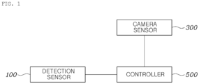
- FIG. 1 is the diagram illustrating the target detection system for a vehicle according to the first embodiment of the present disclosure.
- the target detection system for a vehicle is configured to include the detection sensor 100, the camera sensor 300, and a controller 500.
- the detection sensor 100 detects the target using a reflected wave.
- the camera sensor 300 detects the target using an image.
- the controller 500 computes a risk level through data acquired through the detection sensor 100 and the camera sensor 300.
- the controller 500 may be realized through a nonvolatile memory (not illustrated) and a processor (not illustrated).
- the nonvolatile memory is configured to store data associated with algorithms for controlling operations of various components of the vehicle or with data as to software commands for executing the algorithms.
- the processor is configured to perform operations described below using the data stored in the nonvolatile memory.
- the memory and the processor here may be realized as individual chips, respectively. Alternatively, the memory and the processor may be realized as a single integrated chip.
- the processor may be a single processor or a combination of two or more processors.
- the detection sensor 100 is a sensor that is capable of detecting tracking information (a distance, a speed, an azimuth angle, and the like) of the target on the basis of the reflected wave.
- the detection sensor 100 may be installed on at least one of the front side, rear, and flank of the vehicle.
- the detection sensor 100 may generate the tracking information using the Doppler Effect.
- a Micro-Doppler effect may be used.
- the detection sensor 100 may be a radar, an ultrasonic sensor, a rider sensor, or the like that uses the reflected wave.
- the camera sensor 300 may be installed on at least one of the front, rear, and flank of the vehicle.
- the camera sensor 300 may acquire image data on the vicinity of the vehicle.
- the camera sensor 300 may obtain, through monitoring, an image that includes the warning region that appears to the right side or left side of the vehicle.
- the controller 500 may determine a first risk level through the data acquired through the detection sensor 100.
- the data here acquired by the detection sensor 100 may be the tracking information of the target, such as the distance, the speed, and the azimuth angle.
- the controller 500 may compute a time-to-collision (TTC) and an impact point, as factors for determining the first risk level.
- TTC time-to-collision
- the controller 500 may compute the TTC and the impact point using a position and a speed in the longitudinal direction and a position and a speed in the transverse direction.
- the controller 500 may determine the first risk level, taking this change into consideration.
- the TTC and the impact point are recomputed by adding the change in the speed in the transverse direction to values, respectively, that result from computing the TTC and the impact point.
- the controller 500 determines the first risk level as "risk” or "safety.” At this point, in a case where the recomputed TTC is shorter than a threshold value of the TTC and where the recomputed impact point falls within a threshold value range for the impact point, the first risk level is determined as indicating "risk.” In other cases, the first risk level is determined as indicating "safety.” That is, although the change in the speed in the transverse direction is considered, in a case where the TTC is short and where the impact point is close to the vehicle, the first risk level is determined as indicating the "risk” in such a manner that a warning is generated.
- the camera sensor 300 may obtain an image through monitoring and thus may detect a target.
- the camera sensor 300 may be a sensor that is capable of acquiring an RGB image.
- the controller 500 may determine a second risk level, depending on whether or not the target is detected from the image obtained through the monitoring by the camera sensor 300. Like the first risk level, the second risk level may be determined as indicating the "risk” or the "safety.”
- the controller 500 may extract portions of the left side and right side of the image obtained through monitoring, as the warning regions, from the image. There is a high likelihood that the target detected by the detection sensor 100 will be extracted from the left side and right side of the image obtained by the camera sensor 300. Because of this, the controller 500 may regard the portions of the left side and right side of the image as the warning regions and thus may determine the second risk level. Therefore, in a case where the target is present in the portions extracted as the warning regions, the controller 500 determines the second risk level as "risk.” At this point, in a case where an image change of the warning region occurs, the controller 500 may determine that the target is present. More specifically, when a value of the image change of the warning region is computed and the value of the image change is equal to or higher than a threshold value, the target may be determined as being present, and thus the second risk level may be determined as indicating the "risk.”
- the controller 500 determines a final risk level, taking into consideration the first risk level and the second risk level. In a case where the first risk level and the second risk level both indicate the "risk,” the final risk level is determined as indicating the "risk.” In a case where the first risk level and the second risk level both indicate the "safety,” the final risk level is determined as indicating the "safety.” In a case where the final risk level is the "risk,” the warning is generated. In a case where the final risk level is "safety,” the warning is not generated.
- the final risk level determined as indicating "pending.”
- the final risk level may be determined as indicating the "pending.”
- the generation of the warning is delayed.
- the warning may be generated.
- the reason for this is to alert a driver to a situation that a collision will occur at only one of the first risk level and the second risk level.
- the final risk level may change to the "risk.” In this case, when the generation of the warning is delayed for less than the predetermined time, the warning may be generated.
- the final risk level may be determined as indicating being "high,” “middle,” or “low.” In a case where the first risk level and the second risk level both indicate the “risk,” the final risk level is determined as being “high.” In a case where one of the first risk level and the second risk level both indicates the "risk,” the final risk level is determined as being “middle.” In a case where the first risk level and the second risk level both indicate the "safety,” the final risk level is determined as being “low.” At this point, in a case where the final risk level is determined as being "middle,” the generation of the warning is delayed.
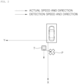
- FIG. 2 is a view illustrating a situation where an erroneous warning occurs because a detected speed and direction change due to a change in a speed in a transverse direction Y even though a target T moves at an actual speed of a target T in a longitudinal direction X.
- the target T may undergo the change in the speed in the transverse direction Y even through a direction in which the target T actually moves is the longitudinal direction X in which a user's vehicle moves.
- the micro-Doppler effect occurs in various portions of his/her body, thereby causing the change in the speed in the transverse direction Y
- This change causes changes in the speed and direction that are detected by the sensor of the vehicle.
- the target T moves toward a point P that the vehicle approaches.
- the erroneous warning is caused to be generated.
- FIG. 3 are graphs showing the information for tracking the target T in a case where the target T detected by the detection sensor 100 moves away in the transverse direction X.
- Graph A shows a change in movement distance of the target T in the longitudinal direction X over time, and a indicates that the movement distance in the longitudinal direction X increases.
- Graph B shows a change in movement distance of the target T in the transverse direction Y overtime, and b indicates that, while the target T moves away, the movement distance of the target T in the transverse direction Y alternately increases and decreases.
- Graph C shows a change in a speed in the longitudinal direction X over time.
- Graph D shows a change in a speed in the transverse direction Y over time.
- d indicates that, even though the target T moves in the longitudinal direction X, the target T undergoes the change in the speed in the transverse direction Y
- Graph E shows that, even though the target T moves away in the longitudinal direction X, Rear Cross Traffic Alert (RCTA) generates the erroneous warning e due to the change in the speed in the transverse direction Y
- RCTA Rear Cross Traffic Alert
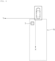
- FIG. 4 is a view illustrating a situation where the target T is positioned at a short distance. More specifically, in a case where the target T is present within a short-distance range N away from the user's vehicle, it is determined that the target T is at the short distance. In a case where the target T is present within the short-distance range N, the controller 500 may start to determine the first risk level. At this time, the first risk level and the second risk level may be determined at the same time.
- the short-distance range N may be a range of impact points, and, specifically, the short distance may fall within the threshold value range for the impact point.
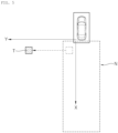
- FIG. 5 is a view illustrating a situation where the target T is positioned more than the threshold distance in the transverse direction Y away from the short distance.
- the controller 500 does not determine the risk level. The reason for this is because if the user's vehicle is no longer at the short distance, there is a low likelihood that a collision risk will occur.
- the movement distance that is out of the short-distance range N in the transverse direction Y may be a threshold distance in the transverse direction Y Therefore, although the target T is initially positioned within the short-distance range N, in a case where the target thereafter moves the threshold distance or longer in the transverse direction Y, the risk level is not determined.
- FIG. 6 is a view illustrating the warning regions that may be detected by the camera sensor 300.
- the camera sensor 300 obtains an image through monitoring and thus detects the target.
- the camera sensor 300 may be installed on at least one of the front, rear, and flank of the vehicle.
- the controller 500 may extract portions of regions that appear to the right side R and left side L, respectively, of the vehicle, as the warning regions, from the image obtained through monitoring. On the basis of the value of the image change of the extracted warning region, the controller 500 may determine whether or not the target T is present.
- the controller 500 may extract the warning region including a parking guidance line, and in this case, the right side R and left side L of the parking guidance line may be the warning regions.
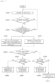
- FIG. 7 is the flowchart illustrating the target detection method for a vehicle according to the second embodiment of the present disclosure.
- the method includes: a step of detecting, by a detection sensor 100, a target using a reflected wave (S 100); a step of determining, by a controller 500, a first risk level of the target, taking into consideration data acquired through the detection sensor 100 and a change in a speed in a transverse direction of the target; a step of determining, the controller 500, a second risk level of the target through data acquired through a camera sensor 300; and a step of computing, the controller 500, a final risk level of the target, taking into consideration both the first risk level and second risk level.
- the detection sensor 100 detects the target, it is determined whether or not the target is initially positioned at a short distance away from a vehicle (S200).
- the target may be continuously detected without determining a risk level.
- the risk level is not determined. That is, although the target is initially positioned at the short distance, in a case where the vehicle thereafter moves a threshold distance or longer in the transverse direction (S300), the risk level is not determined.
- the controller 500 computes a TTC and an impact point on the basis of the data obtained through the detection.
- the controller 500 recomputes the TTC and the impact point, taking into consideration the change in the speed in the transverse direction (S400). That is, the TTC and the impact point are recomputed by adding the change in the speed in the transverse direction to data on the computed TTC and impact point. Then, the controller 500 determines the first risk level on the basis of the recomputed TTC and impact point (S500).
- the camera sensor 300 may monitor whether or not the target is present (S420), and the controller 500 may determine the second risk level using the data acquired through the camera sensor 300.
- the second risk level may be determined (S520), and the first risk level and the second risk level may be determined at the same time (520).
- the controller 500 computes a final risk level, taking into consideration both the first risk level and the second risk level.
- the final risk level is determined as indicating the "risk,” and generates a warning (S600).
- the warning is not generated (S640).
- the final risk level is determined as indicating the "pending,” and the generation of the warning is delayed.
- the generation of the warning is preferentially suppressed (S620).
- the warning may be generated.
Landscapes
- Engineering & Computer Science (AREA)
- Radar, Positioning & Navigation (AREA)
- Remote Sensing (AREA)
- Physics & Mathematics (AREA)
- General Physics & Mathematics (AREA)
- Mechanical Engineering (AREA)
- Automation & Control Theory (AREA)
- Computer Networks & Wireless Communication (AREA)
- Transportation (AREA)
- Human Computer Interaction (AREA)
- Multimedia (AREA)
- Theoretical Computer Science (AREA)
- Mathematical Physics (AREA)
- Electromagnetism (AREA)
- Traffic Control Systems (AREA)
Abstract
Description
- The present application claims priority of
Korean Patent Application No. 10-2021-0139451 filed on October 19, 2021 - The present disclosure relates to a target detection system for a vehicle and a target detection method for a vehicle and, particularly to, a target detection system for a vehicle and a target detection method for a vehicle, the system and the method being capable of improving an erroneous-warning situation that occurs due to an error in a speed in a transverse direction of a vehicle.
- A vehicle system for detecting a target refers to a system that detects a target approaching a blind spot of a user's vehicle and provides prior notice of the target's approaching. As a detection unit of the target detection system, a radar sensor or the like that uses a reflected wave may be used.
- The principle of operation of a radar for a vehicle is to transmit a transmission electromagnetic wave signal from a user's vehicle, to receive an electromagnetic wave signal reflected from a different vehicle or an obstacle, and to estimate a distance or a relative speed between the radar and the different vehicle or the obstacle using a time difference between these two signals and an amount of change in Doppler frequency.
- However, there may occur a problem in that an erroneous warning is generated as a result of erroneous detection due to a type of obstacle, a movement direction, or the like.
- For example, while a person walks, various micro-Doppler effects occur due to movements of his/her head, shoulders, upper body, arms, and legs. That is, the micro-Doppler effects refer to additional Doppler shifts produced by other vibrations and rotations in the person's different portions in addition to the person's platform. The micro-Doppler effect is used when classifying types of targets. However, the micro-Doppler effect causes an error in estimating movement information of the target. The reason for this is because the acquisition of various pieces of detection information from one target causes differences in accuracies of a distance, a speed, and the like, depending on which of the various pieces of detection information is used as representative information. Moreover, because the target recognized as a person has a smaller Radar Cross Section (RCS) than a vehicle, a signal received after being reflected from the target has a small magnitude. Thus, an information error may be further increased.
- Therefore, in a case where the person moves away in a longitudinal direction from a lateral surface of the vehicle, because a distance in a transverse direction between the vehicle and the person is short, in some cases, an erroneous warning is generated. More specifically, in a case where the person gets off a vehicle that stops adjacent to a user's vehicle and moves in the longitudinal direction away from the user's vehicle, an error in a speed in the transverse direction may occur due to a short distance in the transverse direction between the vehicle and the person and the micro-Doppler effect occurring while the person moves. In this case, a condition for generating the erroneous warning is satisfied due to the error of the speed in the transverse direction, and thus there occurs a problem in that a warning system generates the erroneous warning.
- Therefore, there is a growing need for technology development to provide a method for improving an erroneous-warning situation that occurs due to the change in the speed in the transverse direction while the target moves in the longitudinal direction.
- The foregoing is intended merely to aid in understanding the background of the present disclosure and therefore should not be interpreted to admit that the present disclosure falls within the purview of the related art that is already known to a person of ordinary skill in the art.
- An object of the present disclosure, which is proposed to solve the above-mentioned problem, is to provide a target detection system for a vehicle and a target detection method for a vehicle, both of which are capable of computing a final risk level, taking into consideration not only results of recomputing a time-to-collision and an impact point, but also the presence or absence of a target that is detected by a
camera sensor 300. The time-to-collision and the impact point are recomputed, taking into consideration a change in a speed in a transverse direction that occurs when the target moves in a transverse direction. - In order to accomplish the above-mentioned object, according to an aspect of the present disclosure, there is provided a target detection system for a vehicle, the system including: a detection sensor detecting a target based on a reflected wave; a camera sensor monitoring the target based on an image; and a controller determining a first risk level of the target based on data acquired through the detection sensor and a change in a speed in a transverse direction of the target, determining a second risk level of the target based on data acquired through the camera sensor, and computing a final risk level based on both the first risk level and the second risk level.
- In the system, in a case where the target is present within a threshold distance in the transverse direction, the controller may determine the first risk level based on the change in the speed in the transverse direction of the target.
- In the system, the controller may compute a time-to-collision and an impact point, as factors for determining the first risk level, and, in a case where the change in the speed in the transverse direction occurs, the controller may recompute the time-to-collision and the impact point by adding the change in the speed in the transverse direction to the time-to-collision and the impact point.
- In the system, the controller determines the first risk level as indicating "risk" or "safety," and, in a case where the recomputed time-to-collision is shorter than a threshold value and where the recomputed impact point falls within a threshold value range, the controller may determine the first risk level as indicating the "risk."
- In the system, the controller may determine the second risk level as indicating the "risk" or the "safety" and may extract left and right sides of the image obtained by the camera sensor through monitoring, as a warning region, and, in a case where the target is present on the warning region, the controller may determine the second risk level as indicating the "risk." In the system, the controller may compute a value of an image change of the warning region and, when the value of the image change is equal to or higher than a threshold value, the controller may determine the second risk level as indicating the "risk."
- In the system, the controller may determine the first risk level and the second risk level as indicating "risk" or "safety," in a case where the first risk level and the second risk level both indicate the risk, the controller may determine the final risk level as indicating the "risk," and, in a case where the first risk level and the second risk level both indicate the "safety," the controller may determine the final risk level as indicating the "safety."
- In the system, in a case where only one of the first risk level and the second risk level indicates the "risk," the controller may determine the final risk level as "pending," and, in a case where the final risk level indicates the "pending," the controller may delay generation of a warning, and, when the generation of the warning is delayed for a predetermined time or longer, may generate the warning.
- According to another aspect of the present disclosure, there is provided a target detection method for a vehicle, the method including: detecting, by a detection sensor, a target based on a reflected wave; determining, by a controller, a first risk level of the target, taking into consideration data acquired through the detection sensor and a change in a speed of the target in a transverse direction; determining, the controller, a second risk level of the target based on data acquired through a camera sensor; and computing, the controller, a final risk level of the target based on both the first risk level and second risk level.
- According to the present disclosure, even in a case where an error may occur in computing a risk level due to a change in a speed in a transverse direction while a detected target moves in a longitudinal direction, a more precise final risk level can be computed, taking into consideration not only results of both results of recomputing a time-to-collision and an impact point, but also the presence or absence of a target that is detected by a camera sensor. The time-to-collision and the impact point are recomputed, taking into consideration a change in a speed in a transverse direction.
- The above and other objects, features and other advantages of the present disclosure will be clearly understood from the following detailed description when taken in conjunction with the accompanying drawings, in which:
-
FIG. 1 is a block diagram illustrating a target detection system for a vehicle according to a first embodiment of the present disclosure; -
FIG. 2 is a view illustrating a situation where an erroneous warning occurs due to a change in a speed in a transverse direction of a target; -
FIG. 3 are graphs showing information for tracking the target that moves away in a longitudinal direction, the information being acquired through measurement by a detection sensor; -
FIG. 4 is a view illustrating a situation where the target is positioned at a short distance; -
FIG. 5 is a view illustrating a situation where the target is positioned more than a threshold distance in the transverse direction away from the short distance; -
FIG. 6 is a view illustrating warning regions that are detectable by a camera sensor; and -
FIG. 7 is a flowchart illustrating a target detection method for a vehicle according to a second embodiment of the present disclosure. -
FIG. 1 is a block diagram illustrating a target detection system for a vehicle according to a first embodiment of the present disclosure.FIG. 2 is a view illustrating a situation where, even though a target moves in a longitudinal direction, an erroneous warning occurs due to a change in a speed in a transverse direction of a target.FIG. 3 are graphs showing positions in the longitudinal and transverse directions and a speed that are measured by adetection sensor 100 and that are information for tracking the target that moves away in the longitudinal direction and showing generation of the erroneous warning.FIG. 4 is a view illustrating a situation where the target is positioned at a short distance.FIG. 5 is a view illustrating a situation where the target is positioned more than a threshold distance in the transverse direction away from the short distance.FIG. 6 is a view illustrating warning regions that appear to the left side and right side, respectively, of a vehicle, the warning regions being detectable by acamera sensor 300.FIG. 7 is a flowchart illustrating a target detection method for a vehicle according to a second embodiment of the present disclosure. -
FIG. 1 is the diagram illustrating the target detection system for a vehicle according to the first embodiment of the present disclosure. - The target detection system for a vehicle according to the present disclosure is configured to include the
detection sensor 100, thecamera sensor 300, and acontroller 500. Thedetection sensor 100 detects the target using a reflected wave. Thecamera sensor 300 detects the target using an image. Thecontroller 500 computes a risk level through data acquired through thedetection sensor 100 and thecamera sensor 300. - The
controller 500 according to an exemplary embodiment of the present disclosure may be realized through a nonvolatile memory (not illustrated) and a processor (not illustrated). The nonvolatile memory is configured to store data associated with algorithms for controlling operations of various components of the vehicle or with data as to software commands for executing the algorithms. The processor is configured to perform operations described below using the data stored in the nonvolatile memory. The memory and the processor here may be realized as individual chips, respectively. Alternatively, the memory and the processor may be realized as a single integrated chip. The processor may be a single processor or a combination of two or more processors. - The
detection sensor 100 is a sensor that is capable of detecting tracking information (a distance, a speed, an azimuth angle, and the like) of the target on the basis of the reflected wave. Thedetection sensor 100 may be installed on at least one of the front side, rear, and flank of the vehicle. As an implementation example, thedetection sensor 100 may generate the tracking information using the Doppler Effect. Furthermore, a Micro-Doppler effect may be used. Thedetection sensor 100 may be a radar, an ultrasonic sensor, a rider sensor, or the like that uses the reflected wave. - The
camera sensor 300 may be installed on at least one of the front, rear, and flank of the vehicle. Thecamera sensor 300 may acquire image data on the vicinity of the vehicle. As an implementation example, thecamera sensor 300 may obtain, through monitoring, an image that includes the warning region that appears to the right side or left side of the vehicle. - The
controller 500 may determine a first risk level through the data acquired through thedetection sensor 100. The data here acquired by thedetection sensor 100 may be the tracking information of the target, such as the distance, the speed, and the azimuth angle. Thecontroller 500 may compute a time-to-collision (TTC) and an impact point, as factors for determining the first risk level. At this point, thecontroller 500 may compute the TTC and the impact point using a position and a speed in the longitudinal direction and a position and a speed in the transverse direction. Moreover, even though the target moves in the longitudinal direction, in a case where the change in the speed in the transverse direction occurs, thecontroller 500 may determine the first risk level, taking this change into consideration. In this case, the TTC and the impact point are recomputed by adding the change in the speed in the transverse direction to values, respectively, that result from computing the TTC and the impact point. - The
controller 500 determines the first risk level as "risk" or "safety." At this point, in a case where the recomputed TTC is shorter than a threshold value of the TTC and where the recomputed impact point falls within a threshold value range for the impact point, the first risk level is determined as indicating "risk." In other cases, the first risk level is determined as indicating "safety." That is, although the change in the speed in the transverse direction is considered, in a case where the TTC is short and where the impact point is close to the vehicle, the first risk level is determined as indicating the "risk" in such a manner that a warning is generated. - The
camera sensor 300 may obtain an image through monitoring and thus may detect a target. Thecamera sensor 300 may be a sensor that is capable of acquiring an RGB image. Thecontroller 500 may determine a second risk level, depending on whether or not the target is detected from the image obtained through the monitoring by thecamera sensor 300. Like the first risk level, the second risk level may be determined as indicating the "risk" or the "safety." - In addition, the
controller 500 may extract portions of the left side and right side of the image obtained through monitoring, as the warning regions, from the image. There is a high likelihood that the target detected by thedetection sensor 100 will be extracted from the left side and right side of the image obtained by thecamera sensor 300. Because of this, thecontroller 500 may regard the portions of the left side and right side of the image as the warning regions and thus may determine the second risk level. Therefore, in a case where the target is present in the portions extracted as the warning regions, thecontroller 500 determines the second risk level as "risk." At this point, in a case where an image change of the warning region occurs, thecontroller 500 may determine that the target is present. More specifically, when a value of the image change of the warning region is computed and the value of the image change is equal to or higher than a threshold value, the target may be determined as being present, and thus the second risk level may be determined as indicating the "risk." - The
controller 500 determines a final risk level, taking into consideration the first risk level and the second risk level. In a case where the first risk level and the second risk level both indicate the "risk," the final risk level is determined as indicating the "risk." In a case where the first risk level and the second risk level both indicate the "safety," the final risk level is determined as indicating the "safety." In a case where the final risk level is the "risk," the warning is generated. In a case where the final risk level is "safety," the warning is not generated. - In a case where one of the first risk level and the second risk level indicates the "risk," the final risk level determined as indicating "pending." As an implementation example, in a case where the first risk level indicates the "risk" and where the second risk level indicates the "safety," or in a case where the first risk level indicates the "safety" and where the second risk level indicates the "risk," the final risk level may be determined as indicating the "pending."
- In a case where the final risk level indicates "pending," the generation of the warning is delayed. At this point, when the generation of the warning is delayed for a predetermined time or longer, the warning may be generated. The reason for this is to alert a driver to a situation that a collision will occur at only one of the first risk level and the second risk level. In addition, as an implementation example, even after the final risk level is determined as indicating the "pending," because the first and second risk levels continue to be determined, the final risk level may change to the "risk." In this case, when the generation of the warning is delayed for less than the predetermined time, the warning may be generated.
- As an implementation example, the final risk level may be determined as indicating being "high," "middle," or "low." In a case where the first risk level and the second risk level both indicate the "risk," the final risk level is determined as being "high." In a case where one of the first risk level and the second risk level both indicates the "risk," the final risk level is determined as being "middle." In a case where the first risk level and the second risk level both indicate the "safety," the final risk level is determined as being "low." At this point, in a case where the final risk level is determined as being "middle," the generation of the warning is delayed.
-
FIG. 2 is a view illustrating a situation where an erroneous warning occurs because a detected speed and direction change due to a change in a speed in a transverse direction Y even though a target T moves at an actual speed of a target T in a longitudinal direction X. The target T may undergo the change in the speed in the transverse direction Y even through a direction in which the target T actually moves is the longitudinal direction X in which a user's vehicle moves. As an implementation example, in a case where the target T is a person who moves in the longitudinal direction X, the micro-Doppler effect occurs in various portions of his/her body, thereby causing the change in the speed in the transverse direction Y This change causes changes in the speed and direction that are detected by the sensor of the vehicle. Thus, it is erroneously determined that the target T moves toward a point P that the vehicle approaches. Thus, the erroneous warning is caused to be generated. -
FIG. 3 are graphs showing the information for tracking the target T in a case where the target T detected by thedetection sensor 100 moves away in the transverse direction X. Specifically, Graph A shows a change in movement distance of the target T in the longitudinal direction X over time, and a indicates that the movement distance in the longitudinal direction X increases. Graph B shows a change in movement distance of the target T in the transverse direction Y overtime, and b indicates that, while the target T moves away, the movement distance of the target T in the transverse direction Y alternately increases and decreases. Graph C shows a change in a speed in the longitudinal direction X over time. Graph D shows a change in a speed in the transverse direction Y over time. d indicates that, even though the target T moves in the longitudinal direction X, the target T undergoes the change in the speed in the transverse direction Y Graph E shows that, even though the target T moves away in the longitudinal direction X, Rear Cross Traffic Alert (RCTA) generates the erroneous warning e due to the change in the speed in the transverse direction Y -
FIG. 4 is a view illustrating a situation where the target T is positioned at a short distance. More specifically, in a case where the target T is present within a short-distance range N away from the user's vehicle, it is determined that the target T is at the short distance. In a case where the target T is present within the short-distance range N, thecontroller 500 may start to determine the first risk level. At this time, the first risk level and the second risk level may be determined at the same time. As an implementation example, the short-distance range N may be a range of impact points, and, specifically, the short distance may fall within the threshold value range for the impact point. -
FIG. 5 is a view illustrating a situation where the target T is positioned more than the threshold distance in the transverse direction Y away from the short distance. As an implementation example, although the target T is initially present within the short distance range T, in a case where the target T thereafter moves out of the short-distance range N, thecontroller 500 does not determine the risk level. The reason for this is because if the user's vehicle is no longer at the short distance, there is a low likelihood that a collision risk will occur. At this point, the movement distance that is out of the short-distance range N in the transverse direction Y may be a threshold distance in the transverse direction Y Therefore, although the target T is initially positioned within the short-distance range N, in a case where the target thereafter moves the threshold distance or longer in the transverse direction Y, the risk level is not determined. -
FIG. 6 is a view illustrating the warning regions that may be detected by thecamera sensor 300. Thecamera sensor 300 obtains an image through monitoring and thus detects the target. Thecamera sensor 300 may be installed on at least one of the front, rear, and flank of the vehicle. Thecontroller 500 may extract portions of regions that appear to the right side R and left side L, respectively, of the vehicle, as the warning regions, from the image obtained through monitoring. On the basis of the value of the image change of the extracted warning region, thecontroller 500 may determine whether or not the target T is present. More specifically, when the value of the image change of the warning region is computed and the value of the image change is equal to or higher than the threshold value, the target may be determined as being present, and thus the second risk level may be determined as indicating the "risk." As an implementation example, in a case where thecamera sensor 300 is installed on the rear of the vehicle, thecontroller 500 may extract the warning region including a parking guidance line, and in this case, the right side R and left side L of the parking guidance line may be the warning regions. -
FIG. 7 is the flowchart illustrating the target detection method for a vehicle according to the second embodiment of the present disclosure. - With reference to
FIG. 7 , the method includes: a step of detecting, by adetection sensor 100, a target using a reflected wave (S 100); a step of determining, by acontroller 500, a first risk level of the target, taking into consideration data acquired through thedetection sensor 100 and a change in a speed in a transverse direction of the target; a step of determining, thecontroller 500, a second risk level of the target through data acquired through acamera sensor 300; and a step of computing, thecontroller 500, a final risk level of the target, taking into consideration both the first risk level and second risk level. - More particularly, in a case where the
detection sensor 100 detects the target, it is determined whether or not the target is initially positioned at a short distance away from a vehicle (S200). In a case where the target is not positioned at the short distance, the target may be continuously detected without determining a risk level. Although the target is positioned at the short distance from the vehicle, in a case where the vehicle is thereafter out of a short-distance range N, the risk level is not determined. That is, although the target is initially positioned at the short distance, in a case where the vehicle thereafter moves a threshold distance or longer in the transverse direction (S300), the risk level is not determined. - In a case where the target is present within the short-distance range N, the
controller 500 computes a TTC and an impact point on the basis of the data obtained through the detection. At this point, in a case where the target undergoes the change in the speed in the transverse direction, thecontroller 500 recomputes the TTC and the impact point, taking into consideration the change in the speed in the transverse direction (S400). That is, the TTC and the impact point are recomputed by adding the change in the speed in the transverse direction to data on the computed TTC and impact point. Then, thecontroller 500 determines the first risk level on the basis of the recomputed TTC and impact point (S500). At this point, thecamera sensor 300 may monitor whether or not the target is present (S420), and thecontroller 500 may determine the second risk level using the data acquired through thecamera sensor 300. As an implementation example, in a case where the first risk level indicates the "risk," then, the second risk level may be determined (S520), and the first risk level and the second risk level may be determined at the same time (520). - The
controller 500 computes a final risk level, taking into consideration both the first risk level and the second risk level. As an implementation example, in a case where the first risk level and the second risk level both indicate the "risk," the final risk level is determined as indicating the "risk," and generates a warning (S600). Furthermore, in a case where the first risk level and the second risk level both indicate the "safety," the final risk level is determined as indicating the "safety." Thus, the warning is not generated (S640). In a case where only one of the first risk level and the second risk level indicates the "risk," the final risk level is determined as indicating the "pending," and the generation of the warning is delayed. That is, in a case where the final risk level indicates the "pending," even though any one of the first risk level and the second risk level indicates the "risk," the generation of the warning is preferentially suppressed (S620). When the generation of the warning is delayed for a predetermined time or longer, the warning may be generated. - The specific embodiment of the present disclosure is described above with every feature thereof being illustrated in the drawings, and it would be obvious to a person of ordinary skill in the art that various modifications and alterations are possibly made to the present disclosure without departing from the technical idea of the present disclosure that is protected by the following claims.
Claims (15)
- A target detection system for a vehicle, the system comprising:a detection sensor detecting a target based on a wave reflected from the target;a camera sensor monitoring the target based on an image including the target; anda controller determining a first risk level of the target based on data acquired through the detection sensor and a change in a speed in a transverse direction of the target, determining a second risk level of the target based on data acquired through the camera sensor, and computing a final risk level based on both the first risk level and the second risk level.
- The system of claim 1, wherein in a case where the target is present within a threshold distance in the transverse direction, the controller determines the first risk level based on the change in the speed in the transverse direction of the target.
- The system of claim 1 or 2, wherein the controller computes a time-to-collision and an impact point, as factors for determining the first risk level, and
wherein, in a case where the change in the speed in the transverse direction occurs, the controller recomputes the time-to-collision and the impact point by adding the change in the speed in the transverse direction to the time-to-collision and the impact point. - The system of claim 3, wherein the controller determines the first risk level as indicating risk or safety, and
wherein, in a case where the recomputed time-to-collision is shorter than a first threshold value and where the recomputed impact point falls within a second threshold value, the controller determines the first risk level as indicating the risk. - The system of any one of claims 1 to 4, wherein the controller determines the second risk level as indicating risk or safety and extracts left and right sides of the image obtained by the camera sensor through monitoring, as a warning region, and
wherein, in a case where the target is present on the warning region, the controller determines the second risk level as indicating the risk. - The system of claim 4 or 5, wherein the controller computes a value of an image change of the warning region, and
wherein, when the value of the image change is equal to or higher than a threshold value, the controller determines the second risk level as indicating the risk. - The system of any one of claims 1 to 6, wherein the controller determines the first risk level and the second risk level as indicating risk or safety,wherein, in a case where the first risk level and the second risk level both indicate the risk, the controller determines the final risk level as indicating the risk, andwherein, in a case where the first risk level and the second risk level both indicate the safety, the controller determines the final risk level as indicating the safety.
- The system of claim 7, wherein, in a case where only one of the first risk level and the second risk level indicates the risk, the controller determines the final risk level as pending, and
wherein, in a case where the final risk level indicates the pending, the controller delays generation of a warning, and, when the generation of the warning is delayed for a predetermined time or longer, generates the warning. - A target detection method for a vehicle, the method comprising:detecting, by a detection sensor, a target based on a reflected wave;determining, by a controller, a first risk level of the target based on data acquired through the detection sensor and a change in a speed of the target in a transverse direction;determining, by the controller, a second risk level of the target based on data acquired through a camera sensor; andcomputing, by the controller, a final risk level of the target based on both the first risk level and second risk level.
- The method of claim 9, wherein in the determining of the first risk level, in a case where the target moves within a threshold distance in the transverse direction, the first risk level is determined based on the change in the speed in the transverse direction of the target.
- The method of claim 9 or 10, wherein in the determining of the first risk level, a time-to-collision and an impact point are computed as factors for determining the first risk level, and
wherein, in a case where the change in the speed in the transverse direction occurs, the time-to-collision and the impact point are recomputed by adding the change in the speed in the transverse direction to the time-to-collision and the impact point. - The method of claim 11, wherein in the determining of the first risk level, the first risk level is determined as indicating risk or safety, and
wherein, in a case where the recomputed time-to-collision is shorter than a first threshold value and where the recomputed impact point falls within a second threshold value range, the first risk level is determined as indicating the risk. - The method of any one of claims 9 to 12, wherein in the determining of the second risk level, the second risk level is determined as indicating risk or safety and left and right sides of the image obtained by the camera sensor through monitoring are extracted as a warning region, and a value of an image change of the warning region is computed, and
wherein, in a case where the value of the image change of the warning region is equal to or higher than a threshold value, the second risk level is determined as indicating the risk. - The method of any one of claims 9 to 13, wherein in the computing of the final risk level, the first risk level and the second risk level are determined as indicating risk or safety,wherein, in a case where the first risk level and the second risk level both indicate the risk, the final risk level is determined as indicating the risk, andwherein, in a case where the first risk level and the second risk level both indicate the safety, the final risk level is determined as indicating the safety.
- The method of claim 14, wherein in the computing of the final risk level, in a case where only one of the first risk level and the second risk level indicates the risk, the final risk level is determined as pending, and
wherein, in a case where the final risk level indicates the pending, generation of a warning is delayed, and, when the generation of the warning is delayed for a predetermined time or longer, the warning is generated.
Applications Claiming Priority (1)
| Application Number | Priority Date | Filing Date | Title |
|---|---|---|---|
| KR1020210139451A KR20230055722A (en) | 2021-10-19 | 2021-10-19 | A target detection system and method of a vehicle |
Publications (2)
| Publication Number | Publication Date |
|---|---|
| EP4170384A1 true EP4170384A1 (en) | 2023-04-26 |
| EP4170384B1 EP4170384B1 (en) | 2024-06-05 |
Family
ID=82655284
Family Applications (1)
| Application Number | Title | Priority Date | Filing Date |
|---|---|---|---|
| EP22185418.5A Active EP4170384B1 (en) | 2021-10-19 | 2022-07-18 | Target detection system and method for vehicle |
Country Status (4)
| Country | Link |
|---|---|
| US (1) | US11975653B2 (en) |
| EP (1) | EP4170384B1 (en) |
| KR (1) | KR20230055722A (en) |
| CN (1) | CN115993598B (en) |
Families Citing this family (1)
| Publication number | Priority date | Publication date | Assignee | Title |
|---|---|---|---|---|
| CN117002384A (en) * | 2023-04-12 | 2023-11-07 | 深圳市速腾聚创科技有限公司 | A method and device for blind spot early warning |
Citations (3)
| Publication number | Priority date | Publication date | Assignee | Title |
|---|---|---|---|---|
| US20180096604A1 (en) * | 2016-10-03 | 2018-04-05 | Toyota Jidosha Kabushiki Kaisha | Vehicle driving assist apparatus |
| US20180370531A1 (en) * | 2015-12-17 | 2018-12-27 | Denso Corporation | Object detection device and object detection method |
| US20190016316A1 (en) * | 2017-07-13 | 2019-01-17 | Hyundai Motor Company | Vehicle and method for controlling the same |
Family Cites Families (44)
| Publication number | Priority date | Publication date | Assignee | Title |
|---|---|---|---|---|
| AU2002951852A0 (en) * | 2002-10-04 | 2002-10-24 | Rf Innovations Pty Ltd | Proximity detection system and method |
| US6876298B2 (en) * | 2003-03-14 | 2005-04-05 | General Motors Corporation | Audible warning for vehicle safety systems |
| JP4650079B2 (en) * | 2004-11-30 | 2011-03-16 | 日産自動車株式会社 | Object detection apparatus and method |
| JP4426535B2 (en) * | 2006-01-17 | 2010-03-03 | 本田技研工業株式会社 | Vehicle periphery monitoring device |
| US7859432B2 (en) * | 2007-05-23 | 2010-12-28 | Che Il Electric Wireing Devices Co., Ltd. | Collision avoidance system based on detection of obstacles in blind spots of vehicle |
| US8552848B2 (en) * | 2007-08-16 | 2013-10-08 | Ford Global Technologies, Llc | System and method for combined blind spot detection and rear crossing path collision warning |
| JP5341705B2 (en) * | 2009-10-15 | 2013-11-13 | 本田技研工業株式会社 | Vehicle travel safety device |
| JP2011118483A (en) * | 2009-11-30 | 2011-06-16 | Fujitsu Ten Ltd | On-vehicle device and recognition support system |
| US8427340B2 (en) * | 2009-12-08 | 2013-04-23 | Jovan Palmieri | Multi-mode safety system for spotter-assisted vehicle maneuvering |
| DE102011001533B4 (en) * | 2010-03-30 | 2022-02-17 | Subaru Corporation | Driving support device for a vehicle |
| US20120277957A1 (en) * | 2010-04-15 | 2012-11-01 | Satoru Inoue | Driving assist device |
| US9230419B2 (en) * | 2010-07-27 | 2016-01-05 | Rite-Hite Holding Corporation | Methods and apparatus to detect and warn proximate entities of interest |
| US8611598B2 (en) * | 2011-07-26 | 2013-12-17 | Harman International (China) Holdings Co., Ltd. | Vehicle obstacle detection system |
| JP5867273B2 (en) * | 2012-04-27 | 2016-02-24 | 富士通株式会社 | Approaching object detection device, approaching object detection method, and computer program for approaching object detection |
| JPWO2014064805A1 (en) * | 2012-10-25 | 2016-09-05 | 日産自動車株式会社 | Vehicle travel support device |
| US9174672B2 (en) * | 2013-10-28 | 2015-11-03 | GM Global Technology Operations LLC | Path planning for evasive steering maneuver in presence of target vehicle and surrounding objects |
| US9988047B2 (en) * | 2013-12-12 | 2018-06-05 | Magna Electronics Inc. | Vehicle control system with traffic driving control |
| KR101521870B1 (en) | 2013-12-19 | 2015-05-20 | 만도헬라일렉트로닉스(주) | Rear Radar for Vehicle and the Controlling Method thereof |
| US9266472B2 (en) * | 2014-02-20 | 2016-02-23 | GM Global Technology Operations LLC | Systems and methods to indicate clearance for vehicle door |
| JP6262068B2 (en) * | 2014-04-25 | 2018-01-17 | 日立建機株式会社 | Near-body obstacle notification system |
| JP6397801B2 (en) * | 2015-06-30 | 2018-09-26 | 日立オートモティブシステムズ株式会社 | Object detection device |
| JP6654977B2 (en) * | 2016-07-04 | 2020-02-26 | 株式会社Soken | Own vehicle position specifying device and own vehicle position specifying method |
| US10179584B2 (en) * | 2017-01-31 | 2019-01-15 | Aptiv Technologies Limited | Parking-assist system |
| JPWO2018155159A1 (en) * | 2017-02-24 | 2019-12-19 | パナソニックIpマネジメント株式会社 | Remote video output system and remote video output device |
| JP2018156462A (en) * | 2017-03-17 | 2018-10-04 | 東芝メモリ株式会社 | Mobile object and driving support system including the same |
| KR101977716B1 (en) * | 2017-11-03 | 2019-05-14 | 주식회사 만도 | Safety apparatus of vehicle and method using thereof |
| FR3077547A1 (en) * | 2018-02-08 | 2019-08-09 | Renault S.A.S | SYSTEM AND METHOD FOR DETECTING A RISK OF COLLISION BETWEEN A MOTOR VEHICLE AND A SECONDARY OBJECT LOCATED ON CIRCULATION PATHS ADJACENT TO THE VEHICLE DURING CHANGE OF TRACK |
| JP7180077B2 (en) * | 2018-02-16 | 2022-11-30 | マツダ株式会社 | vehicle controller |
| JP7006460B2 (en) * | 2018-04-02 | 2022-01-24 | 株式会社Jvcケンウッド | Vehicle display control device, vehicle display system, vehicle display control method, and program |
| KR102628282B1 (en) * | 2018-10-10 | 2024-01-24 | 현대자동차주식회사 | Vehicle and control method thereof |
| KR102621247B1 (en) * | 2018-12-07 | 2024-01-08 | 현대자동차주식회사 | Vehicle, method of controlling vehicle, and seat belt apparatus |
| US20200298758A1 (en) * | 2019-03-18 | 2020-09-24 | GM Global Technology Operations LLC | System and method of animal detection and warning during vehicle start up |
| DE102019121650A1 (en) * | 2019-06-04 | 2020-12-10 | Inventus Engineering Gmbh | Method for controlling door movements of a door of a motor vehicle and motor vehicle components |
| KR102610762B1 (en) * | 2019-07-08 | 2023-12-07 | 현대자동차주식회사 | Safe Exit Assist system |
| US11180148B2 (en) * | 2019-09-03 | 2021-11-23 | Ford Global Technologies, Llc | Detection and response to confined trailer in system-assisted hitch operation |
| KR102331927B1 (en) * | 2019-12-30 | 2021-12-01 | 주식회사 에이치엘클레무브 | Driver assistance system |
| US11686836B2 (en) * | 2020-01-13 | 2023-06-27 | Pony Ai Inc. | Real-time and dynamic localization using active doppler sensing systems for vehicles |
| KR102473404B1 (en) * | 2020-02-25 | 2022-12-02 | 삼성전기주식회사 | Apparatus for providing top view |
| KR20210126442A (en) * | 2020-04-10 | 2021-10-20 | 현대모비스 주식회사 | Rearward warning system for vehicle and its method |
| CN112285716A (en) * | 2020-10-13 | 2021-01-29 | 安徽江淮汽车集团股份有限公司 | Blind spot monitoring system alarm time length adjusting method, device, equipment and storage medium |
| US11780433B2 (en) * | 2020-10-21 | 2023-10-10 | Denso Corporation | Systems and methods for selectively modifying collision alert thresholds |
| US11827240B2 (en) * | 2020-12-09 | 2023-11-28 | Uatc, Llc | Systems and methods for costing autonomous vehicle maneuvers |
| KR20220137216A (en) * | 2021-04-01 | 2022-10-12 | 현대자동차주식회사 | Vehicle rear warning system and control method thereof |
| US11794737B2 (en) * | 2021-04-07 | 2023-10-24 | Ford Global Technologies, Llc | Vehicle operation |
-
2021
- 2021-10-19 KR KR1020210139451A patent/KR20230055722A/en active Pending
-
2022
- 2022-07-18 EP EP22185418.5A patent/EP4170384B1/en active Active
- 2022-08-18 US US17/890,639 patent/US11975653B2/en active Active
- 2022-08-23 CN CN202211011095.8A patent/CN115993598B/en active Active
Patent Citations (3)
| Publication number | Priority date | Publication date | Assignee | Title |
|---|---|---|---|---|
| US20180370531A1 (en) * | 2015-12-17 | 2018-12-27 | Denso Corporation | Object detection device and object detection method |
| US20180096604A1 (en) * | 2016-10-03 | 2018-04-05 | Toyota Jidosha Kabushiki Kaisha | Vehicle driving assist apparatus |
| US20190016316A1 (en) * | 2017-07-13 | 2019-01-17 | Hyundai Motor Company | Vehicle and method for controlling the same |
Also Published As
| Publication number | Publication date |
|---|---|
| KR20230055722A (en) | 2023-04-26 |
| US20230119420A1 (en) | 2023-04-20 |
| US11975653B2 (en) | 2024-05-07 |
| CN115993598A (en) | 2023-04-21 |
| CN115993598B (en) | 2026-03-24 |
| EP4170384B1 (en) | 2024-06-05 |
Similar Documents
| Publication | Publication Date | Title |
|---|---|---|
| US6888447B2 (en) | Obstacle detection device for vehicle and method thereof | |
| CN101663594B (en) | Driver assistance system and method for determining the plausibility of objects | |
| US7710247B2 (en) | Object recognizing apparatus | |
| US20180342160A1 (en) | Overhead structure determination device and driving assistance system | |
| US8610620B2 (en) | Object detecting apparatus and object detecting method | |
| US9102329B2 (en) | Tracking control apparatus | |
| US20140333467A1 (en) | Object detection device | |
| US8165797B2 (en) | Vehicular control object determination system and vehicular travel locus estimation system | |
| US7714769B2 (en) | Method for estimating the width of radar objects | |
| US6380885B2 (en) | Obstacle recognition system for vehicle | |
| JP7401273B2 (en) | Mobile body control device and method | |
| WO2017138329A1 (en) | Collision prediction device | |
| EP2100164A2 (en) | Surroundings monitoring apparatus | |
| EP4170384A1 (en) | Target detection system and method for vehicle | |
| JP2002175599A (en) | Lane position estimation device for preceding vehicle or target | |
| US12024175B2 (en) | Vehicle system for detection of oncoming vehicles | |
| US20050004719A1 (en) | Device and method for determining the position of objects in the surroundings of a motor vehicle | |
| JP2002296350A (en) | Object detection device | |
| US6947841B2 (en) | Method for identifying obstacles for a motor vehicle, using at least three distance sensors for identifying the lateral extension of an object | |
| US20050060117A1 (en) | Method and device for determination of the distance of a sensor device to an object | |
| EP3413083A1 (en) | A vehicle system for detection of oncoming vehicles | |
| KR20230061858A (en) | Warning system and control method of a vehicle | |
| KR20210158238A (en) | Radar sensor covering detection system and method for vehicle |
Legal Events
| Date | Code | Title | Description |
|---|---|---|---|
| PUAI | Public reference made under article 153(3) epc to a published international application that has entered the european phase |
Free format text: ORIGINAL CODE: 0009012 |
|
| STAA | Information on the status of an ep patent application or granted ep patent |
Free format text: STATUS: REQUEST FOR EXAMINATION WAS MADE |
|
| 17P | Request for examination filed |
Effective date: 20220718 |
|
| AK | Designated contracting states |
Kind code of ref document: A1 Designated state(s): AL AT BE BG CH CY CZ DE DK EE ES FI FR GB GR HR HU IE IS IT LI LT LU LV MC MK MT NL NO PL PT RO RS SE SI SK SM TR |
|
| GRAP | Despatch of communication of intention to grant a patent |
Free format text: ORIGINAL CODE: EPIDOSNIGR1 |
|
| STAA | Information on the status of an ep patent application or granted ep patent |
Free format text: STATUS: GRANT OF PATENT IS INTENDED |
|
| RIC1 | Information provided on ipc code assigned before grant |
Ipc: G01S 15/931 20200101ALN20231220BHEP Ipc: G01S 13/58 20060101ALN20231220BHEP Ipc: G01S 13/72 20060101ALI20231220BHEP Ipc: G01S 7/41 20060101ALI20231220BHEP Ipc: G01S 13/931 20200101ALI20231220BHEP Ipc: G01S 13/86 20060101AFI20231220BHEP |
|
| INTG | Intention to grant announced |
Effective date: 20240123 |
|
| RIN1 | Information on inventor provided before grant (corrected) |
Inventor name: KANG, EUN SEOK |
|
| P01 | Opt-out of the competence of the unified patent court (upc) registered |
Effective date: 20240223 |
|
| GRAS | Grant fee paid |
Free format text: ORIGINAL CODE: EPIDOSNIGR3 |
|
| GRAA | (expected) grant |
Free format text: ORIGINAL CODE: 0009210 |
|
| STAA | Information on the status of an ep patent application or granted ep patent |
Free format text: STATUS: THE PATENT HAS BEEN GRANTED |
|
| AK | Designated contracting states |
Kind code of ref document: B1 Designated state(s): AL AT BE BG CH CY CZ DE DK EE ES FI FR GB GR HR HU IE IS IT LI LT LU LV MC MK MT NL NO PL PT RO RS SE SI SK SM TR |
|
| REG | Reference to a national code |
Ref country code: CH Ref legal event code: EP |
|
| REG | Reference to a national code |
Ref country code: DE Ref legal event code: R096 Ref document number: 602022003773 Country of ref document: DE |
|
| REG | Reference to a national code |
Ref country code: IE Ref legal event code: FG4D |
|
| REG | Reference to a national code |
Ref country code: LT Ref legal event code: MG9D |
|
| PG25 | Lapsed in a contracting state [announced via postgrant information from national office to epo] |
Ref country code: BG Free format text: LAPSE BECAUSE OF FAILURE TO SUBMIT A TRANSLATION OF THE DESCRIPTION OR TO PAY THE FEE WITHIN THE PRESCRIBED TIME-LIMIT Effective date: 20240605 |
|
| REG | Reference to a national code |
Ref country code: NL Ref legal event code: MP Effective date: 20240605 |
|
| PG25 | Lapsed in a contracting state [announced via postgrant information from national office to epo] |
Ref country code: HR Free format text: LAPSE BECAUSE OF FAILURE TO SUBMIT A TRANSLATION OF THE DESCRIPTION OR TO PAY THE FEE WITHIN THE PRESCRIBED TIME-LIMIT Effective date: 20240605 Ref country code: FI Free format text: LAPSE BECAUSE OF FAILURE TO SUBMIT A TRANSLATION OF THE DESCRIPTION OR TO PAY THE FEE WITHIN THE PRESCRIBED TIME-LIMIT Effective date: 20240605 |
|
| PG25 | Lapsed in a contracting state [announced via postgrant information from national office to epo] |
Ref country code: GR Free format text: LAPSE BECAUSE OF FAILURE TO SUBMIT A TRANSLATION OF THE DESCRIPTION OR TO PAY THE FEE WITHIN THE PRESCRIBED TIME-LIMIT Effective date: 20240906 |
|
| PG25 | Lapsed in a contracting state [announced via postgrant information from national office to epo] |
Ref country code: ES Free format text: LAPSE BECAUSE OF FAILURE TO SUBMIT A TRANSLATION OF THE DESCRIPTION OR TO PAY THE FEE WITHIN THE PRESCRIBED TIME-LIMIT Effective date: 20240605 |
|
| PG25 | Lapsed in a contracting state [announced via postgrant information from national office to epo] |
Ref country code: LV Free format text: LAPSE BECAUSE OF FAILURE TO SUBMIT A TRANSLATION OF THE DESCRIPTION OR TO PAY THE FEE WITHIN THE PRESCRIBED TIME-LIMIT Effective date: 20240605 |
|
| PG25 | Lapsed in a contracting state [announced via postgrant information from national office to epo] |
Ref country code: NO Free format text: LAPSE BECAUSE OF FAILURE TO SUBMIT A TRANSLATION OF THE DESCRIPTION OR TO PAY THE FEE WITHIN THE PRESCRIBED TIME-LIMIT Effective date: 20240905 Ref country code: LV Free format text: LAPSE BECAUSE OF FAILURE TO SUBMIT A TRANSLATION OF THE DESCRIPTION OR TO PAY THE FEE WITHIN THE PRESCRIBED TIME-LIMIT Effective date: 20240605 Ref country code: HR Free format text: LAPSE BECAUSE OF FAILURE TO SUBMIT A TRANSLATION OF THE DESCRIPTION OR TO PAY THE FEE WITHIN THE PRESCRIBED TIME-LIMIT Effective date: 20240605 Ref country code: GR Free format text: LAPSE BECAUSE OF FAILURE TO SUBMIT A TRANSLATION OF THE DESCRIPTION OR TO PAY THE FEE WITHIN THE PRESCRIBED TIME-LIMIT Effective date: 20240906 Ref country code: FI Free format text: LAPSE BECAUSE OF FAILURE TO SUBMIT A TRANSLATION OF THE DESCRIPTION OR TO PAY THE FEE WITHIN THE PRESCRIBED TIME-LIMIT Effective date: 20240605 Ref country code: ES Free format text: LAPSE BECAUSE OF FAILURE TO SUBMIT A TRANSLATION OF THE DESCRIPTION OR TO PAY THE FEE WITHIN THE PRESCRIBED TIME-LIMIT Effective date: 20240605 Ref country code: BG Free format text: LAPSE BECAUSE OF FAILURE TO SUBMIT A TRANSLATION OF THE DESCRIPTION OR TO PAY THE FEE WITHIN THE PRESCRIBED TIME-LIMIT Effective date: 20240605 Ref country code: RS Free format text: LAPSE BECAUSE OF FAILURE TO SUBMIT A TRANSLATION OF THE DESCRIPTION OR TO PAY THE FEE WITHIN THE PRESCRIBED TIME-LIMIT Effective date: 20240905 |
|
| PG25 | Lapsed in a contracting state [announced via postgrant information from national office to epo] |
Ref country code: NL Free format text: LAPSE BECAUSE OF FAILURE TO SUBMIT A TRANSLATION OF THE DESCRIPTION OR TO PAY THE FEE WITHIN THE PRESCRIBED TIME-LIMIT Effective date: 20240605 |
|
| REG | Reference to a national code |
Ref country code: AT Ref legal event code: MK05 Ref document number: 1692849 Country of ref document: AT Kind code of ref document: T Effective date: 20240605 |
|
| PG25 | Lapsed in a contracting state [announced via postgrant information from national office to epo] |
Ref country code: NL Free format text: LAPSE BECAUSE OF FAILURE TO SUBMIT A TRANSLATION OF THE DESCRIPTION OR TO PAY THE FEE WITHIN THE PRESCRIBED TIME-LIMIT Effective date: 20240605 |
|
| PG25 | Lapsed in a contracting state [announced via postgrant information from national office to epo] |
Ref country code: PT Free format text: LAPSE BECAUSE OF FAILURE TO SUBMIT A TRANSLATION OF THE DESCRIPTION OR TO PAY THE FEE WITHIN THE PRESCRIBED TIME-LIMIT Effective date: 20241007 |
|
| PG25 | Lapsed in a contracting state [announced via postgrant information from national office to epo] |
Ref country code: PT Free format text: LAPSE BECAUSE OF FAILURE TO SUBMIT A TRANSLATION OF THE DESCRIPTION OR TO PAY THE FEE WITHIN THE PRESCRIBED TIME-LIMIT Effective date: 20241007 |
|
| PG25 | Lapsed in a contracting state [announced via postgrant information from national office to epo] |
Ref country code: PL Free format text: LAPSE BECAUSE OF FAILURE TO SUBMIT A TRANSLATION OF THE DESCRIPTION OR TO PAY THE FEE WITHIN THE PRESCRIBED TIME-LIMIT Effective date: 20240605 |
|
| PG25 | Lapsed in a contracting state [announced via postgrant information from national office to epo] |
Ref country code: EE Free format text: LAPSE BECAUSE OF FAILURE TO SUBMIT A TRANSLATION OF THE DESCRIPTION OR TO PAY THE FEE WITHIN THE PRESCRIBED TIME-LIMIT Effective date: 20240605 |
|
| PG25 | Lapsed in a contracting state [announced via postgrant information from national office to epo] |
Ref country code: AT Free format text: LAPSE BECAUSE OF FAILURE TO SUBMIT A TRANSLATION OF THE DESCRIPTION OR TO PAY THE FEE WITHIN THE PRESCRIBED TIME-LIMIT Effective date: 20240605 Ref country code: IS Free format text: LAPSE BECAUSE OF FAILURE TO SUBMIT A TRANSLATION OF THE DESCRIPTION OR TO PAY THE FEE WITHIN THE PRESCRIBED TIME-LIMIT Effective date: 20241005 |
|
| PG25 | Lapsed in a contracting state [announced via postgrant information from national office to epo] |
Ref country code: CZ Free format text: LAPSE BECAUSE OF FAILURE TO SUBMIT A TRANSLATION OF THE DESCRIPTION OR TO PAY THE FEE WITHIN THE PRESCRIBED TIME-LIMIT Effective date: 20240605 |
|
| PG25 | Lapsed in a contracting state [announced via postgrant information from national office to epo] |
Ref country code: SK Free format text: LAPSE BECAUSE OF FAILURE TO SUBMIT A TRANSLATION OF THE DESCRIPTION OR TO PAY THE FEE WITHIN THE PRESCRIBED TIME-LIMIT Effective date: 20240605 Ref country code: RO Free format text: LAPSE BECAUSE OF FAILURE TO SUBMIT A TRANSLATION OF THE DESCRIPTION OR TO PAY THE FEE WITHIN THE PRESCRIBED TIME-LIMIT Effective date: 20240605 |
|
| PG25 | Lapsed in a contracting state [announced via postgrant information from national office to epo] |
Ref country code: SM Free format text: LAPSE BECAUSE OF FAILURE TO SUBMIT A TRANSLATION OF THE DESCRIPTION OR TO PAY THE FEE WITHIN THE PRESCRIBED TIME-LIMIT Effective date: 20240605 |
|
| PG25 | Lapsed in a contracting state [announced via postgrant information from national office to epo] |
Ref country code: SM Free format text: LAPSE BECAUSE OF FAILURE TO SUBMIT A TRANSLATION OF THE DESCRIPTION OR TO PAY THE FEE WITHIN THE PRESCRIBED TIME-LIMIT Effective date: 20240605 Ref country code: SK Free format text: LAPSE BECAUSE OF FAILURE TO SUBMIT A TRANSLATION OF THE DESCRIPTION OR TO PAY THE FEE WITHIN THE PRESCRIBED TIME-LIMIT Effective date: 20240605 Ref country code: RO Free format text: LAPSE BECAUSE OF FAILURE TO SUBMIT A TRANSLATION OF THE DESCRIPTION OR TO PAY THE FEE WITHIN THE PRESCRIBED TIME-LIMIT Effective date: 20240605 Ref country code: PL Free format text: LAPSE BECAUSE OF FAILURE TO SUBMIT A TRANSLATION OF THE DESCRIPTION OR TO PAY THE FEE WITHIN THE PRESCRIBED TIME-LIMIT Effective date: 20240605 Ref country code: IS Free format text: LAPSE BECAUSE OF FAILURE TO SUBMIT A TRANSLATION OF THE DESCRIPTION OR TO PAY THE FEE WITHIN THE PRESCRIBED TIME-LIMIT Effective date: 20241005 Ref country code: EE Free format text: LAPSE BECAUSE OF FAILURE TO SUBMIT A TRANSLATION OF THE DESCRIPTION OR TO PAY THE FEE WITHIN THE PRESCRIBED TIME-LIMIT Effective date: 20240605 Ref country code: CZ Free format text: LAPSE BECAUSE OF FAILURE TO SUBMIT A TRANSLATION OF THE DESCRIPTION OR TO PAY THE FEE WITHIN THE PRESCRIBED TIME-LIMIT Effective date: 20240605 Ref country code: AT Free format text: LAPSE BECAUSE OF FAILURE TO SUBMIT A TRANSLATION OF THE DESCRIPTION OR TO PAY THE FEE WITHIN THE PRESCRIBED TIME-LIMIT Effective date: 20240605 |
|
| PG25 | Lapsed in a contracting state [announced via postgrant information from national office to epo] |
Ref country code: IT Free format text: LAPSE BECAUSE OF FAILURE TO SUBMIT A TRANSLATION OF THE DESCRIPTION OR TO PAY THE FEE WITHIN THE PRESCRIBED TIME-LIMIT Effective date: 20240605 |
|
| REG | Reference to a national code |
Ref country code: DE Ref legal event code: R097 Ref document number: 602022003773 Country of ref document: DE |
|
| PG25 | Lapsed in a contracting state [announced via postgrant information from national office to epo] |
Ref country code: LU Free format text: LAPSE BECAUSE OF NON-PAYMENT OF DUE FEES Effective date: 20240718 |
|
| PG25 | Lapsed in a contracting state [announced via postgrant information from national office to epo] |
Ref country code: MC Free format text: LAPSE BECAUSE OF FAILURE TO SUBMIT A TRANSLATION OF THE DESCRIPTION OR TO PAY THE FEE WITHIN THE PRESCRIBED TIME-LIMIT Effective date: 20240605 |
|
| PG25 | Lapsed in a contracting state [announced via postgrant information from national office to epo] |
Ref country code: MC Free format text: LAPSE BECAUSE OF FAILURE TO SUBMIT A TRANSLATION OF THE DESCRIPTION OR TO PAY THE FEE WITHIN THE PRESCRIBED TIME-LIMIT Effective date: 20240605 Ref country code: LU Free format text: LAPSE BECAUSE OF NON-PAYMENT OF DUE FEES Effective date: 20240718 |
|
| PLBE | No opposition filed within time limit |
Free format text: ORIGINAL CODE: 0009261 |
|
| STAA | Information on the status of an ep patent application or granted ep patent |
Free format text: STATUS: NO OPPOSITION FILED WITHIN TIME LIMIT |
|
| PG25 | Lapsed in a contracting state [announced via postgrant information from national office to epo] |
Ref country code: DK Free format text: LAPSE BECAUSE OF FAILURE TO SUBMIT A TRANSLATION OF THE DESCRIPTION OR TO PAY THE FEE WITHIN THE PRESCRIBED TIME-LIMIT Effective date: 20240605 |
|
| PG25 | Lapsed in a contracting state [announced via postgrant information from national office to epo] |
Ref country code: BE Free format text: LAPSE BECAUSE OF NON-PAYMENT OF DUE FEES Effective date: 20240731 |
|
| 26N | No opposition filed |
Effective date: 20250306 |
|
| REG | Reference to a national code |
Ref country code: BE Ref legal event code: MM Effective date: 20240731 |
|
| PGFP | Annual fee paid to national office [announced via postgrant information from national office to epo] |
Ref country code: FR Payment date: 20250611 Year of fee payment: 4 |
|
| PG25 | Lapsed in a contracting state [announced via postgrant information from national office to epo] |
Ref country code: IE Free format text: LAPSE BECAUSE OF NON-PAYMENT OF DUE FEES Effective date: 20240718 |
|
| PG25 | Lapsed in a contracting state [announced via postgrant information from national office to epo] |
Ref country code: SE Free format text: LAPSE BECAUSE OF FAILURE TO SUBMIT A TRANSLATION OF THE DESCRIPTION OR TO PAY THE FEE WITHIN THE PRESCRIBED TIME-LIMIT Effective date: 20240605 |
|
| PGFP | Annual fee paid to national office [announced via postgrant information from national office to epo] |
Ref country code: DE Payment date: 20250609 Year of fee payment: 4 |
|
| PG25 | Lapsed in a contracting state [announced via postgrant information from national office to epo] |
Ref country code: CY Free format text: LAPSE BECAUSE OF FAILURE TO SUBMIT A TRANSLATION OF THE DESCRIPTION OR TO PAY THE FEE WITHIN THE PRESCRIBED TIME-LIMIT; INVALID AB INITIO Effective date: 20220718 |
|
| REG | Reference to a national code |
Ref country code: CH Ref legal event code: H13 Free format text: ST27 STATUS EVENT CODE: U-0-0-H10-H13 (AS PROVIDED BY THE NATIONAL OFFICE) Effective date: 20260224 |
|
| PG25 | Lapsed in a contracting state [announced via postgrant information from national office to epo] |
Ref country code: HU Free format text: LAPSE BECAUSE OF FAILURE TO SUBMIT A TRANSLATION OF THE DESCRIPTION OR TO PAY THE FEE WITHIN THE PRESCRIBED TIME-LIMIT; INVALID AB INITIO Effective date: 20220718 |
|
| PG25 | Lapsed in a contracting state [announced via postgrant information from national office to epo] |
Ref country code: CH Free format text: LAPSE BECAUSE OF NON-PAYMENT OF DUE FEES Effective date: 20250731 |