EP4170313A1 - Vehicle detection system and vehicle detection method - Google Patents
Vehicle detection system and vehicle detection method Download PDFInfo
- Publication number
- EP4170313A1 EP4170313A1 EP21826059.4A EP21826059A EP4170313A1 EP 4170313 A1 EP4170313 A1 EP 4170313A1 EP 21826059 A EP21826059 A EP 21826059A EP 4170313 A1 EP4170313 A1 EP 4170313A1
- Authority
- EP
- European Patent Office
- Prior art keywords
- image acquisition
- vehicle detection
- detection system
- controller
- sensor
- Prior art date
- Legal status (The legal status is an assumption and is not a legal conclusion. Google has not performed a legal analysis and makes no representation as to the accuracy of the status listed.)
- Pending
Links
- 238000001514 detection method Methods 0.000 title claims abstract description 146
- 230000008859 change Effects 0.000 claims abstract description 27
- 238000000034 method Methods 0.000 claims abstract description 8
- 238000011282 treatment Methods 0.000 claims description 46
- 230000001133 acceleration Effects 0.000 claims description 3
- 230000008569 process Effects 0.000 abstract description 6
- 238000004364 calculation method Methods 0.000 abstract description 4
- 238000005259 measurement Methods 0.000 abstract description 3
- 230000006872 improvement Effects 0.000 description 22
- 230000006870 function Effects 0.000 description 10
- 102100034112 Alkyldihydroxyacetonephosphate synthase, peroxisomal Human genes 0.000 description 5
- 101000799143 Homo sapiens Alkyldihydroxyacetonephosphate synthase, peroxisomal Proteins 0.000 description 5
- 230000002159 abnormal effect Effects 0.000 description 5
- 238000000848 angular dependent Auger electron spectroscopy Methods 0.000 description 5
- 238000004891 communication Methods 0.000 description 3
- 238000004590 computer program Methods 0.000 description 3
- 238000006073 displacement reaction Methods 0.000 description 3
- 238000003860 storage Methods 0.000 description 3
- 230000000007 visual effect Effects 0.000 description 3
- 238000004458 analytical method Methods 0.000 description 2
- 238000013500 data storage Methods 0.000 description 2
- 238000012423 maintenance Methods 0.000 description 2
- 230000005236 sound signal Effects 0.000 description 2
- 206010039203 Road traffic accident Diseases 0.000 description 1
- 230000009471 action Effects 0.000 description 1
- 238000004026 adhesive bonding Methods 0.000 description 1
- 238000013459 approach Methods 0.000 description 1
- 238000004422 calculation algorithm Methods 0.000 description 1
- 230000015556 catabolic process Effects 0.000 description 1
- 238000006731 degradation reaction Methods 0.000 description 1
- 238000011161 development Methods 0.000 description 1
- 230000000694 effects Effects 0.000 description 1
- 238000005516 engineering process Methods 0.000 description 1
- 230000007774 longterm Effects 0.000 description 1
- 230000007246 mechanism Effects 0.000 description 1
- 238000010295 mobile communication Methods 0.000 description 1
- 238000012986 modification Methods 0.000 description 1
- 230000004048 modification Effects 0.000 description 1
- 238000005457 optimization Methods 0.000 description 1
- 230000009467 reduction Effects 0.000 description 1
- 239000007787 solid Substances 0.000 description 1
- 238000011895 specific detection Methods 0.000 description 1
- 238000006467 substitution reaction Methods 0.000 description 1
- 238000003466 welding Methods 0.000 description 1
Images

Classifications
-
- G—PHYSICS
- G06—COMPUTING; CALCULATING OR COUNTING
- G06T—IMAGE DATA PROCESSING OR GENERATION, IN GENERAL
- G06T7/00—Image analysis
- G06T7/80—Analysis of captured images to determine intrinsic or extrinsic camera parameters, i.e. camera calibration
-
- H—ELECTRICITY
- H04—ELECTRIC COMMUNICATION TECHNIQUE
- H04N—PICTORIAL COMMUNICATION, e.g. TELEVISION
- H04N17/00—Diagnosis, testing or measuring for television systems or their details
- H04N17/002—Diagnosis, testing or measuring for television systems or their details for television cameras
-
- G—PHYSICS
- G07—CHECKING-DEVICES
- G07C—TIME OR ATTENDANCE REGISTERS; REGISTERING OR INDICATING THE WORKING OF MACHINES; GENERATING RANDOM NUMBERS; VOTING OR LOTTERY APPARATUS; ARRANGEMENTS, SYSTEMS OR APPARATUS FOR CHECKING NOT PROVIDED FOR ELSEWHERE
- G07C5/00—Registering or indicating the working of vehicles
- G07C5/08—Registering or indicating performance data other than driving, working, idle, or waiting time, with or without registering driving, working, idle or waiting time
- G07C5/0841—Registering performance data
- G07C5/085—Registering performance data using electronic data carriers
-
- F—MECHANICAL ENGINEERING; LIGHTING; HEATING; WEAPONS; BLASTING
- F16—ENGINEERING ELEMENTS AND UNITS; GENERAL MEASURES FOR PRODUCING AND MAINTAINING EFFECTIVE FUNCTIONING OF MACHINES OR INSTALLATIONS; THERMAL INSULATION IN GENERAL
- F16M—FRAMES, CASINGS OR BEDS OF ENGINES, MACHINES OR APPARATUS, NOT SPECIFIC TO ENGINES, MACHINES OR APPARATUS PROVIDED FOR ELSEWHERE; STANDS; SUPPORTS
- F16M11/00—Stands or trestles as supports for apparatus or articles placed thereon ; Stands for scientific apparatus such as gravitational force meters
- F16M11/02—Heads
- F16M11/04—Means for attachment of apparatus; Means allowing adjustment of the apparatus relatively to the stand
- F16M11/043—Allowing translations
- F16M11/046—Allowing translations adapted to upward-downward translation movement
-
- F—MECHANICAL ENGINEERING; LIGHTING; HEATING; WEAPONS; BLASTING
- F16—ENGINEERING ELEMENTS AND UNITS; GENERAL MEASURES FOR PRODUCING AND MAINTAINING EFFECTIVE FUNCTIONING OF MACHINES OR INSTALLATIONS; THERMAL INSULATION IN GENERAL
- F16M—FRAMES, CASINGS OR BEDS OF ENGINES, MACHINES OR APPARATUS, NOT SPECIFIC TO ENGINES, MACHINES OR APPARATUS PROVIDED FOR ELSEWHERE; STANDS; SUPPORTS
- F16M11/00—Stands or trestles as supports for apparatus or articles placed thereon ; Stands for scientific apparatus such as gravitational force meters
- F16M11/02—Heads
- F16M11/18—Heads with mechanism for moving the apparatus relatively to the stand
-
- F—MECHANICAL ENGINEERING; LIGHTING; HEATING; WEAPONS; BLASTING
- F16—ENGINEERING ELEMENTS AND UNITS; GENERAL MEASURES FOR PRODUCING AND MAINTAINING EFFECTIVE FUNCTIONING OF MACHINES OR INSTALLATIONS; THERMAL INSULATION IN GENERAL
- F16M—FRAMES, CASINGS OR BEDS OF ENGINES, MACHINES OR APPARATUS, NOT SPECIFIC TO ENGINES, MACHINES OR APPARATUS PROVIDED FOR ELSEWHERE; STANDS; SUPPORTS
- F16M11/00—Stands or trestles as supports for apparatus or articles placed thereon ; Stands for scientific apparatus such as gravitational force meters
- F16M11/42—Stands or trestles as supports for apparatus or articles placed thereon ; Stands for scientific apparatus such as gravitational force meters with arrangement for propelling the support stands on wheels
-
- G—PHYSICS
- G01—MEASURING; TESTING
- G01B—MEASURING LENGTH, THICKNESS OR SIMILAR LINEAR DIMENSIONS; MEASURING ANGLES; MEASURING AREAS; MEASURING IRREGULARITIES OF SURFACES OR CONTOURS
- G01B11/00—Measuring arrangements characterised by the use of optical techniques
- G01B11/26—Measuring arrangements characterised by the use of optical techniques for measuring angles or tapers; for testing the alignment of axes
- G01B11/275—Measuring arrangements characterised by the use of optical techniques for measuring angles or tapers; for testing the alignment of axes for testing wheel alignment
- G01B11/2755—Measuring arrangements characterised by the use of optical techniques for measuring angles or tapers; for testing the alignment of axes for testing wheel alignment using photoelectric detection means
-
- G—PHYSICS
- G06—COMPUTING; CALCULATING OR COUNTING
- G06T—IMAGE DATA PROCESSING OR GENERATION, IN GENERAL
- G06T7/00—Image analysis
- G06T7/70—Determining position or orientation of objects or cameras
-
- H—ELECTRICITY
- H04—ELECTRIC COMMUNICATION TECHNIQUE
- H04N—PICTORIAL COMMUNICATION, e.g. TELEVISION
- H04N23/00—Cameras or camera modules comprising electronic image sensors; Control thereof
- H04N23/60—Control of cameras or camera modules
- H04N23/695—Control of camera direction for changing a field of view, e.g. pan, tilt or based on tracking of objects
-
- G—PHYSICS
- G01—MEASURING; TESTING
- G01B—MEASURING LENGTH, THICKNESS OR SIMILAR LINEAR DIMENSIONS; MEASURING ANGLES; MEASURING AREAS; MEASURING IRREGULARITIES OF SURFACES OR CONTOURS
- G01B2210/00—Aspects not specifically covered by any group under G01B, e.g. of wheel alignment, caliper-like sensors
- G01B2210/10—Wheel alignment
- G01B2210/12—Method or fixture for calibrating the wheel aligner
-
- G—PHYSICS
- G01—MEASURING; TESTING
- G01B—MEASURING LENGTH, THICKNESS OR SIMILAR LINEAR DIMENSIONS; MEASURING ANGLES; MEASURING AREAS; MEASURING IRREGULARITIES OF SURFACES OR CONTOURS
- G01B2210/00—Aspects not specifically covered by any group under G01B, e.g. of wheel alignment, caliper-like sensors
- G01B2210/10—Wheel alignment
- G01B2210/14—One or more cameras or other optical devices capable of acquiring a two-dimensional image
- G01B2210/143—One or more cameras on each side of a vehicle in the main embodiment
-
- G—PHYSICS
- G06—COMPUTING; CALCULATING OR COUNTING
- G06T—IMAGE DATA PROCESSING OR GENERATION, IN GENERAL
- G06T2207/00—Indexing scheme for image analysis or image enhancement
- G06T2207/30—Subject of image; Context of image processing
- G06T2207/30248—Vehicle exterior or interior
- G06T2207/30252—Vehicle exterior; Vicinity of vehicle
Definitions
- the present application relates to the technical field of automobile detection, and more particularly to a vehicle detection system and a vehicle detection method.
- ADAS Advanced Driver Assistant System
- the detection of wheel positioning parameters is generally realized by a four-wheel aligner, and the hardware in ADAS is calibrated and detected by automobile calibration equipment, so as to reasonably calibrate the wheels and the hardware in the ADAS, thereby ensuring that the owner can drive safely.
- the inventors of the present invention come to the conclusion that: when the current four-wheel aligner or calibration equipment is disturbed by serious external forces, such as vibration, impact or strike, etc. its calculation precision will decrease, or even fail; the user or maintenance personnel cannot timely acquire the information of measurement and calculation precision decrease or failure, which will lead to the miscorrection of the wheel or the hardware in the ADAS, and when in severe conditions, may cause serious traffic accidents.
- Embodiments of the present invention are intended to provide a vehicle detection system and a vehicle detection method so as to solve the technical problem of the miscorrection of a vehicle after the current four-wheel aligner or calibration equipment is interfered.
- a vehicle detection system comprising:
- the failure sensor is fixed to the image acquisition sensor.
- the failure sensor is integrated inside the image acquisition device.
- the failure sensor includes at least one of an acceleration sensor, a pressure sensor, and a gyroscope.
- the support comprises:
- the support comprises a vertical frame assembly and a cross beam assembly; the cross beam assembly is mounted to the vertical frame assembly, the cross beam assembly and the vertical frame assembly are slidingly fit in the vertical direction, and the image acquisition device is mounted to the cross beam assembly.
- the machine vision module comprises two of the image acquisition devices provided at intervals on the cross beam assembly; the controller is housed within the vertical frame assembly or the cross beam assembly.
- an associated image acquisition device and an associated target are further included; wherein the machine vision module comprises two image acquisition devices, the associated image acquisition device is fixed to one of the two image acquisition devices and is electrically connected to the controller, the associated target is fixed to the other one of the two image acquisition devices, the associated image acquisition device is used for acquiring position information about the associated target relative to the associated image acquisition device, and the associated target is a planar target.
- one image acquisition device comprises at least two image acquisition sensors, the failure sensor being fixed to the image acquisition sensor and one image acquisition sensor corresponding to one failure sensor.
- the machine vision module further comprises an image processor, the image processor is respectively electrically connected to the image acquisition sensor and the controller, and the image processor is integrally provided with the controller.
- an output module electrically connected to the controller is further included, wherein the output module is used for outputting a determination result of the controller; the output module comprises a display device and/or a sound output device.
- a target to be detected is further included, the target to be detected being used for being mounted to a wheel and the image acquisition device being used for acquiring an image of the target to be detected.
- the controller is used for determining, according to the motion parameter signal, whether the position of the image acquisition sensor needs to be calibrated, comprising: the controller being used for executing a first intervention treatment when the motion parameter signal is greater than a first preset threshold.
- the first intervention treatment comprises: locking a detection function of the vehicle detection system; and/or the first intervention treatment comprises: controlling the output module to output a first warning signal.
- the controller is used for determining, according to the motion parameter signal, whether the position of the image acquisition sensor needs to be calibrated, comprising: the controller being used for executing a second intervention treatment when the motion parameter signal is greater than a second preset threshold and less than or equal to the first preset threshold.
- the second intervention treatment comprises: controlling the output module to output a second warning signal.
- the number of the controllers is the same as that of the failure sensors, one controller being correspondingly electrically connected to one failure sensor, and both the controller and the failure sensor being integrated into a corresponding image acquisition device.
- an output module is further included, wherein the output module corresponds to the image acquisition device in a one-to-one correspondence, the output module is integrated into a corresponding image acquisition device and electrically connected to the controller, and the output module is used to output the determination result of the controller.
- a vehicle detection method applied to the vehicle detection system comprises steps of:
- determining whether the position of the image acquisition sensor needs to be calibrated, and if so, executing the intervention treatment comprise: executing a first intervention treatment when the motion parameter signal is greater than the first preset threshold.
- the vehicle detection system further includes an output module electrically connected to the controller;
- determining whether the position of the image acquisition sensor needs to be calibrated, and if so, executing the intervention treatment further comprise: executing a second intervention treatment when the motion parameter signal is greater than a second preset threshold and less than or equal to the first preset threshold.
- the second intervention treatment comprises: controlling the output module to output a second warning signal.
- Embodiments of the present invention provide a vehicle detection system that includes a support, a machine vision module, a failure sensor, and a controller.
- the machine vision module comprises at least one image acquisition device, the image acquisition device comprising an image acquisition sensor, and the image acquisition sensor being used for acquiring relevant parameters of hardware to be detected on the vehicle.
- the failure sensor is used for acquiring the position change information of the image acquisition sensor and outputting a motion parameter signal including the position change information.
- the controller is used for determining whether the position of the image acquisition sensor needs to be calibrated according to the motion parameter signal.
- the controller can determine in real time whether the position of the image sensor needs to be calibrated, so as to avoid a miscorrection caused by detecting and correcting the vehicle without precalibration after the measurement and calculation precision of the vehicle detection system is reduced, thereby avoiding the occurrence of dangerous accidents.
- mounting includes welding, screwing, clamping, gluing, etc. to fix or restrain a certain element or device in a specific position or place.
- the element or device may either be fixed in a specific position or place, or may be movable within a limited range.
- the element or device may or may not be detachable after being fixed or restrained in the specific position or place, and is not limited in the embodiments of the present invention.
- the vehicle detection system comprises a support 100, a machine vision module 200, a failure sensor 300, and a controller 400.
- the support 100 is used for mounting and supporting various structures such as the machine vision module 200, the failure sensor 300, and the controller 400, etc.
- the machine vision module 200 is mounted to the support 100 and includes at least one image acquisition device 210 that is fixed in position relative to the support 100; the image acquisition device 210 includes an image acquisition sensor 212 for acquiring an image having related parameters of hardware to be detected of a vehicle to be detected (not shown).
- the failure sensor 300 is used for acquiring the position change information of the image acquisition sensor 212 and outputting a motion parameter signal comprising the position change information.
- the controller 400 is electrically connected to the failure sensor 300 for determining whether the position of the image acquisition sensor 212 needs to be calibrated based on the motion parameter signal output by the failure sensor 300. It is worth noting that "electrically connected" in this embodiment means that the communication of electrical signals between two structures can be realized either by a wired electrical connection via a cable or by a radio connection via Bluetooth, WiFi module, etc.
- the base 110 includes a main body 112 having an I-shape as a whole and several driving wheels 113 mounted to the bottom of the main body 112.
- the vertical frame assembly 120 is mounted to the top of the main body of the base 110 and extends in the vertical direction as shown.
- Mounted to the vertical frame assembly 120 and extending in the illustrated horizontal direction is a cross beam assembly 130 that is slidingly fitted with the vertical frame assembly 120 along the vertical direction shown in the figure.
- the cross beam assembly 130 can be moved or stopped in the illustrated vertical direction in a timely manner driven by an external corresponding driving assembly.
- the machine vision module 200 described above, with particular reference to Figs. 2 and 3 in conjunction with Fig. 1 includes at least two image acquisition devices 210 mounted to the cross beam assembly 130 in a fixed position relative to the support 100.
- the number of the image acquisition devices 210 is two, and the two image acquisition devices 210 are arranged at intervals on the cross beam assembly 130; it could be understood that in other embodiments of the present invention, the number of image acquisition devices 210 may be other numbers, such as one, or three and more.
- the image acquisition device 210 is detachably fixed to the cross beam assembly 130 and is switchable between a locked state and an unlocked state; in the locked state, the image acquisition device 210 is fixed relative to the support 100, and in the unlocked state, the image acquisition device 210 can be adjusted in the position either by a user or a maintenance person manually, or under the action of an external driving mechanism, so as to adapt to the detection requirements of different vehicle types.
- the image acquisition device 210 includes a housing 211 and an image acquisition sensor 212 mounted to the housing 211.
- the housing 211 is fixed to the cross beam assembly 130 by means of a detachable connection, and the image acquisition sensor 212 is mounted on the housing 211 and has the function of acquiring an external image; in the present embodiment, the image acquisition sensor 212 is specifically used for acquiring an image having relevant parameters of hardware to be detected of a wheel on a vehicle to be detected, or a target mounted on the vehicle, etc.
- the failure sensor 300 is relatively fixed in position with the image acquisition sensor 212 in the image acquisition device 210, and is used for detecting the position change information of the image acquisition sensor 212 and outputting a motion parameter signal having the position change information to the controller 400.
- the failure sensor 300 comprises at least one of an acceleration sensor, a pressure sensor, and a gyroscope; it could be understood that the failure sensor 300 is not limited to the selection among the above-described sensors, and may be other sensors as long as it is capable of detecting the position change information of the image acquisition sensor and outputting a motion parameter signal having the position change information.
- the failure sensor 300 is fixed to the housing 211. Specifically, in the same image acquisition device 210, the image acquisition sensor 212 is fixed in position with respect to the housing 211, and the failure sensor 300 indirectly acquires the position change information of the image acquisition sensor 212 by detecting the position change information of the housing 211.
- the failure sensor 300 may be fixed to the outer surface of the housing 211, or may be integrated into the interior of the image acquisition device 210, such as the inner surface of the housing 211 or the internal circuit board of the image acquisition device 210.
- the failure sensor 300 is fixed to the image acquisition sensor 212 and directly detects position change information of the image acquisition sensor 212.
- the number of image acquisition sensors 212 in the same image acquisition device 210 can be one or more, and each image acquisition sensor 212 is fixed relative to the housing 211; or the number of the image acquisition sensors 212 in the same image acquisition device 210 is one or more, and the position of each image acquisition sensor 212 relative to the housing 211 may change such as angular displacement, etc.
- the failure sensor 300 corresponds to the image acquisition sensors 212 one-to-one; alternatively, the number of the image capturing sensors 212 in the same image acquisition device 210 is two or more, wherein some of the image capturing sensors 212 are fixed in position relative to the housing 211, and the position of some of the image capturing sensors 212 relative to the housing 211 can be changed such as angular displacement, etc. and then each image capturing sensor which can be changed in displacement corresponds to a failure sensor 300.
- the controller 400 is in electrical communication with the image acquisition device 210 and the failure sensor 300, respectively.
- the controller 400 is an independent structure that is mounted to the base 110 and electrically connected to failure sensor 300 via the cable 410. It could be understood that in some other embodiments of the present invention, the controller 400 may be housed within vertical frame assembly 120 or the cross beam assembly 130, or integrated within the image acquisition device 210.
- the controller 400 is used for receiving an image having relevant parameters of the hardware to be detected collected by the image acquisition device 210 and parsing the same to obtain a detection result.
- the controller 400 is also used for receiving the motion parameter signal output by the failure sensor 300 and determining whether the position of the image acquisition sensor 212 needs to be calibrated based on the motion parameter signal.
- the controller 400 is used for executing a first intervention treatment when the motion parameter signal is greater than a first preset threshold; the first preset threshold is one reference value preset by the controller 400 itself, and when the motion parameter signal is higher than the first threshold, the detection precision of the vehicle detection system is seriously disturbed, and the detection result is obviously abnormal.
- the first intervention treatment comprises: locking the detection function of the vehicle detection system.
- the user can know that the vehicle detection system is in an unstable state through the first intervention treatment, then correct the vehicle detection system by reasonable means, and then unlock the detection function of the vehicle detection system, so as to avoid a safety accident caused by the vehicle being corrected under the wrong detection precision.
- the vehicle detection system further comprises an output module 500.
- the output module 500 is electrically connected to the controller 400 via another cable 410 for outputting a determination result from the controller 400 about whether the position of the image acquisition sensor 212 needs to be calibrated.
- the first intervention treatment executed by the controller 400 further includes: controlling the output module 500 to output a first warning signal.
- the output module 500 comprises a display device, and the above-mentioned first warning signal comprises visual information such as an image, characters, numbers, symbols, etc. output by the display device; for example, in some implementation modes, the first alert signal includes the following textual content: "the detection system is abnormal, please calibrate the position of image acquisition sensor in time”.
- the output module 500 further comprises a sound output device, and the above-mentioned first warning signal further comprises a sound signal output by the sound output device; for example, in some implementation modes, the first warning signal includes the following sound content: "the detection system is abnormal, please calibrate the position of image acquisition sensor in time”.
- the output module 500 is a display that includes a display device and a sound output device at the same time. It could be understood that in other embodiments of the invention, the output module may also comprise only any one of a display device and a sound output device.
- the controller is used for determining, according to the motion parameter signal, whether the position of the image acquisition sensor needs to be calibrated, comprising: the controller 400 being used for executing a second intervention treatment when the above-mentioned motion parameter signal is greater than a second pre-set threshold and is less than or equal to the first preset threshold; and for not executing any intervention treatment when the motion parameter signal is less than or equal to the second parameter threshold.
- the second preset threshold is one value pre-set by the controller 400 itself, and is less than the first preset threshold; when the above-mentioned motion parameter signal is greater than the second preset threshold and is less than or equal to the first preset threshold, the detection precision of the vehicle detection system is slightly affected, and the detection result has little difference compared with the actual situation and thus can be used; when the above-mentioned motion parameter signal is less than or equal to the second preset threshold, the detection precision of the vehicle detection system is unaffected or minimally affected without affecting the specific detection function.
- the second intervention treatment comprises: controlling the output module 500 to output a second warning signal.
- the second warning signal may be an image signal output by the display device or a sound signal output by the sound output device, but may also be a signal output by a combination of the display device and the sound output device.
- the output module 500 outputs the second warning signal, the user can clearly know the degree to which the detection is affected caused by the vehicle detection system subjected to the impact, thereby deciding whether to calibrate the vehicle detection system according to actual requirements.
- the present invention is not limited thereto.
- the number of controllers 400 is the same as that of the failure sensor 300, a controller 400 is correspondingly electrically connected to a failure sensor 300, and the controller 400 and the failure sensor 300 are both integrated into the corresponding image acquisition device 210; as another example, the controller 400, the failure sensor 300, and the output module 500 have the same number, a controller 400 is correspondingly electrically connected to a failure sensor 300 and an output module 500, and the corresponding controller 400, failure sensor 300, and the output module 500 are all integrated into the corresponding image acquisition device 210.
- the controller 400 includes a processor 401 and a memory 402, which may be connected via a bus or otherwise.
- the image acquisition device 210, the failure sensor 300, and the output module 500 in the machine vision module 200 are all connected to a bus.
- the memory 402 is a non-volatile computer-readable storage medium that can be used to store non-volatile software programs, non-volatile computer-executable programs, and modules.
- the processor 401 executes the steps executed by the controller described above by executing non-volatile software programs, instructions, and modules stored in memory 402.
- the memory 402 may comprise a program storage area and a data storage area.
- the program storage area may store an operating system and an application program required by at least one function; the data storage area may store data output from the image acquisition device 210, the image processor, the failure sensor 300, and the like.
- the memory 402 may include high speed random access memory and may also include non-volatile memory, such as at least one disc memory device, flash memory device, or other non-volatile solid state memory device.
- the memory 402 may alternatively include a memory remotely provided with respect to the processor 401.
- the remote memory may be connected to the processor 401 via a network. Examples of such networks include, but are not limited to, the Internet, intranets, local area networks, mobile communication networks, and combinations thereof.
- the program instructions/modules are stored in the memory 402 and, when executed by one or more processors 401, execute the steps executed by the controller described above.
- the machine vision module 200 further comprises an associated image acquisition device 220 and an associated target 230. Specifically, in conjunction with Figs.
- the associated image acquisition device 220 is fixed to one of the two image acquisition devices 210 and is electrically connected to the controller 400, and the associated target 230 is fixed to the other of the two image acquisition devices.
- the associated image acquisition device 220 is used for acquiring the position information about the associated target 230 relative to itself so as to establish a mutual position relationship between the two image acquisition devices 210, and then obtaining the relation between the positional relationship between the left front wheel, the left rear wheel, the rear front wheel, and the right rear wheel of the vehicle to be detected, and other relevant parameters.
- the associated target is a planar target.
- the failure sensor 300 is built into the associated image acquisition device 220 and the associated target 230. Specifically, a failure sensor 300 is built into the associated image acquisition device 220 and a failure sensor 300 is built into the associated target 230. Further, considering that the image acquisition device 210 directly acquires the image with a wheel to obtain the relevant parameters of the wheel, a relatively rigorous and precise algorithm is required to realize the analysis of the wheel parameters. To overcome this drawback, the vehicle detection system also includes a target to be detected (not shown).
- the target to be detected is used for being mounted on a wheel of a vehicle to be detected
- the image acquisition device 210 is used for acquiring an image of the target to be detected
- the image acquisition device 210 can identify the target to be detected more simply than directly identifying the wheel itself
- the controller can calculate relevant parameters of the wheel from the position of the target to be detected in the image and analyze the detection result.
- the machine vision module 200 further comprises an image processor (not shown), which is electrically connected to the image acquisition device 210 and the controller 400 respectively, and is used for receiving an image having the relevant parameters of the hardware to be detected acquired by two image acquisition devices 210 and an image having the associated target 230 acquired by the associated image acquisition device 220 and performing optimization treatments such as noise reduction, etc. so as to improve the rate and accuracy of the analysis by the controller 400.
- the image processor and the controller 400 are integrally provided; it could be understood that in other embodiments of the present invention, the image processor may also be provided independently from the controller 400 or integrated within the image acquisition device 210.
- An embodiment of the present invention provides a vehicle detection system that includes a support 100, a machine vision module 200, a failure sensing module 300, and a controller 400.
- the machine vision module 200 comprises at least one image acquisition device 210 comprising an image acquisition sensor 212 for acquiring relevant parameters of the hardware to be detected on the vehicle.
- the failure sensor 300 is used to acquire the position change information of the image acquisition sensor 212, and outputs a motion parameter signal including the position change information to the controller 400.
- the controller 400 is electrically connected to the failure sensor 300, and is used for determining whether the position of the image acquisition sensor needs to be calibrated according to the motion parameter signal, so as to avoid a miscorrection caused by detecting and correcting the vehicle without precalibration after the detection precision of the vehicle detection system is significantly reduced, thereby avoiding the occurrence of dangerous accidents.
- the vehicle detection system further comprises an output module 500.
- the vehicle detection system can lock the detection function of the vehicle detection system according to the degree of impact on the image acquisition sensor 212 and the degree of reduced detection precision, so as to warn a user to correct the vehicle detection system in time; it is also possible to output different warning signals or no warning signal through the output module 500, so that the user can know the affected degree of the detection precision of the vehicle detection system in time, thereby prompting the user to correct the vehicle detection system in time.
- the present invention also provides another vehicle detection system.
- a vehicle detection system in the present embodiment, including a support 100', a machine vision module 200', a failure sensor (not shown), a controller 400', and an output module 500'.
- the support 100' includes a vertical frame assembly 120' and a cross beam assembly 130'.
- the cross beam assembly 130' is fixed to the vertical frame assembly 120'.
- the machine vision module 200' includes at least one image acquisition device 210' mounted to the cross beam assembly 130'.
- the failure sensor is built into the image acquisition device 210'.
- the controller 400' is mounted to the cross beam assembly 130'.
- the output module 500 is a mobile terminal such as a mobile phone, a tablet, etc. and is electrically connected to the controller 400 in a wireless communication manner.
- the vehicle detection system in the first embodiment is hereinafter referred to as a first vehicle detection system, and similarly, the vehicle detection system in the present embodiment is referred to as a second vehicle detection system.
- the second vehicle detection system and the first vehicle detection system have substantially the same structural composition, and the two differ from each other mainly in that:
- the scope of application of the first vehicle detection system is wide, and the scope of application of the second vehicle detection system is narrow; however, since the output module 500' is a mobile terminal, a user can be away from structures such as the support 100' during use, which has the advantages of convenience and safety.
- the present invention also provides a vehicle detection method, which is applied to the vehicle detection system in any of the above-described embodiments.
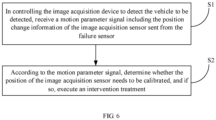
- Fig. 6 which is a schematic flow chart of the vehicle detection method, and in conjunction with Figs. 1 to 3 , the vehicle detection method comprises the steps of
- the first intervention treatment comprises: a detection function that locks the vehicle detection system; then, the user may be alerted to correct the vehicle detection system in time.
- the first intervention treatment further comprises: controlling the output module to output a first warning signal; according to the difference in the actual structure of the output module 500, it being the scenario that the first warning signal may be visual information such as images, characters, symbols, etc. and may also be audible information such as sounds, etc.; then, after acquiring the first warning signal, it being possible that the user corrects the vehicle detection system in time to ensure an accurate detection result.
- the first intervention treatment described above may also include only one of the two approaches described above.
- the second intervention treatment comprises steps as follows: the controller 400 controls the output module 500 to output a second warning signal; according to the different actual structures of the output module 500, the second warning signal can be visual information such as images, characters, symbols, etc. and can also be audible information such as sounds, etc.; then, after acquiring the second warning signal, the user can correct the vehicle detection system in time to ensure a more accurate detection result.
- the vehicle detection method provided by an embodiment of the present invention is used in the detection process of a vehicle to be detected by a vehicle detection system. Since the controller 400 can acquire the position change information about the image acquisition sensor 212 in the image acquisition device 210 in real time via the failure sensor 300, that is to say, the controller 400 can make matching intervention treatment or no intervention treatment according to the position change information about the image acquisition sensor 212 in real time, it is ensured that the vehicle detection system performs a detection process only when the detection precision is good, so as to obtain a reasonable detection result. Therefore, safety accidents caused by the vehicle hardware miscorrection based on the abnormal detection result are avoided.
- an embodiment of the present invention also provides a non-volatile computer storage medium having stored thereon computer-executable instructions that, when executed by one or more processors, such as one processor 401 in Fig. 4 , may cause the one or more processors to execute the steps executed by the controller described above.
- an embodiment of the present invention also provides a computer program product comprising a computer program stored on a non-volatile computer readable storage medium, the computer program comprising a program instruction that, when executed by the electronic equipment, causes the electronic equipment to execute the steps executed by the controller described above.
Landscapes
- Engineering & Computer Science (AREA)
- General Engineering & Computer Science (AREA)
- Mechanical Engineering (AREA)
- Physics & Mathematics (AREA)
- General Physics & Mathematics (AREA)
- Theoretical Computer Science (AREA)
- Computer Vision & Pattern Recognition (AREA)
- Multimedia (AREA)
- Signal Processing (AREA)
- General Health & Medical Sciences (AREA)
- Biomedical Technology (AREA)
- Health & Medical Sciences (AREA)
- Traffic Control Systems (AREA)
- Image Processing (AREA)
- Studio Devices (AREA)
Abstract
Description
- The present application claims priority to the
Chinese patent application No. 202010567583.1 entitled "vehicle detection system and vehicle detection method" filed on June 19, 2020 - The present application relates to the technical field of automobile detection, and more particularly to a vehicle detection system and a vehicle detection method.
- With the development of science and technology and the improvement of living standards, the number of residents' cars is growing rapidly, and cars have become the most popular means of transportation for residents. After a long-term and long-range driving, the wheels or the hardware on the Advanced Driver Assistant System (hereinafter referred to as ADAS) may be subjected to position shift or performance degradation relative to factory settings. At present, the detection of wheel positioning parameters is generally realized by a four-wheel aligner, and the hardware in ADAS is calibrated and detected by automobile calibration equipment, so as to reasonably calibrate the wheels and the hardware in the ADAS, thereby ensuring that the owner can drive safely.
- In carrying out the present invention, the inventors of the present invention come to the conclusion that: when the current four-wheel aligner or calibration equipment is disturbed by serious external forces, such as vibration, impact or strike, etc. its calculation precision will decrease, or even fail; the user or maintenance personnel cannot timely acquire the information of measurement and calculation precision decrease or failure, which will lead to the miscorrection of the wheel or the hardware in the ADAS, and when in severe conditions, may cause serious traffic accidents.
- Embodiments of the present invention are intended to provide a vehicle detection system and a vehicle detection method so as to solve the technical problem of the miscorrection of a vehicle after the current four-wheel aligner or calibration equipment is interfered.
- The embodiments of the present invention solve the technical problems by adopting the following technical solutions:
a vehicle detection system, comprising: - a support;
- a machine vision module mounted to the support, wherein the machine vision module comprises at least one image acquisition device, a position of the image acquisition device relative to the support is fixed, and the image acquisition device comprises an image acquisition sensor for acquiring an image having relevant parameters of hardware to be detected on a vehicle;
- a failure sensor for acquiring position change information about the image acquisition sensor and outputting a motion parameter signal comprising the position change information;
- and a controller electrically connected to the failure sensor for determining whether the position of the image acquisition sensor needs to be calibrated according to the motion parameter signal.
- As a further improvement of the above technical solution, the failure sensor is fixed to the image acquisition sensor.
- As a further improvement of the above technical solution, the failure sensor is integrated inside the image acquisition device.
- As a further improvement of the above technical solution, the failure sensor includes at least one of an acceleration sensor, a pressure sensor, and a gyroscope.
- As a further improvement of the above technical solution, the support comprises:
- a base, a bottom of the base comprising a driving wheel;
- a vertical frame assembly mounted to the base and extending in the vertical direction; and a cross beam assembly mounted to the vertical frame assembly, the cross beam assembly and the vertical frame assembly slidingly fit in the vertical direction, and the image acquisition device being mounted to the cross beam assembly.
- As a further improvement of the above technical solution, the support comprises a vertical frame assembly and a cross beam assembly;
the cross beam assembly is mounted to the vertical frame assembly, the cross beam assembly and the vertical frame assembly are slidingly fit in the vertical direction, and the image acquisition device is mounted to the cross beam assembly. - As a further improvement of the above technical solution, the machine vision module comprises two of the image acquisition devices provided at intervals on the cross beam assembly;
the controller is housed within the vertical frame assembly or the cross beam assembly. - As a further improvement of the above-mentioned technical solution, an associated image acquisition device and an associated target are further included;
wherein the machine vision module comprises two image acquisition devices, the associated image acquisition device is fixed to one of the two image acquisition devices and is electrically connected to the controller, the associated target is fixed to the other one of the two image acquisition devices, the associated image acquisition device is used for acquiring position information about the associated target relative to the associated image acquisition device, and the associated target is a planar target. - As a further improvement of the above-mentioned technical solution, one image acquisition device comprises at least two image acquisition sensors, the failure sensor being fixed to the image acquisition sensor and one image acquisition sensor corresponding to one failure sensor.
- As a further improvement of the above-mentioned technical solution, the machine vision module further comprises an image processor, the image processor is respectively electrically connected to the image acquisition sensor and the controller, and the image processor is integrally provided with the controller.
- As a further improvement of the above-mentioned technical solution, an output module electrically connected to the controller is further included, wherein the output module is used for outputting a determination result of the controller;
the output module comprises a display device and/or a sound output device. - As a further improvement of the above-mentioned technical solution, a target to be detected is further included, the target to be detected being used for being mounted to a wheel and the image acquisition device being used for acquiring an image of the target to be detected.
- As a further improvement of the above technical solution, the controller is used for determining, according to the motion parameter signal, whether the position of the image acquisition sensor needs to be calibrated, comprising:
the controller being used for executing a first intervention treatment when the motion parameter signal is greater than a first preset threshold. - As a further improvement of the above technical solution, the first intervention treatment comprises: locking a detection function of the vehicle detection system;
and/or the first intervention treatment comprises: controlling the output module to output a first warning signal. - As a further improvement of the above technical solution, the controller is used for determining, according to the motion parameter signal, whether the position of the image acquisition sensor needs to be calibrated, comprising:
the controller being used for executing a second intervention treatment when the motion parameter signal is greater than a second preset threshold and less than or equal to the first preset threshold. - As a further improvement of the above technical solution, the second intervention treatment comprises: controlling the output module to output a second warning signal.
- As a further improvement of the above technical solution, the number of the controllers is the same as that of the failure sensors, one controller being correspondingly electrically connected to one failure sensor, and both the controller and the failure sensor being integrated into a corresponding image acquisition device.
- As a further improvement of the above technical solution, an output module is further included, wherein the output module corresponds to the image acquisition device in a one-to-one correspondence, the output module is integrated into a corresponding image acquisition device and electrically connected to the controller, and the output module is used to output the determination result of the controller.
- The embodiments of the present invention solve the technical problems by further adopting the following technical solutions:
a vehicle detection method applied to the vehicle detection system. The method comprises steps of: - receiving a motion parameter signal comprising position change information of the image acquisition sensor sent by the failure sensor while controlling the image acquisition device to detect the vehicle;
- and determining whether the position of the image acquisition sensor needs to be calibrated according to the motion parameter signal, and if so, executing an intervention treatment.
- As a further improvement of the above technical solution, determining whether the position of the image acquisition sensor needs to be calibrated, and if so, executing the intervention treatment, comprise:
executing a first intervention treatment when the motion parameter signal is greater than the first preset threshold. - As a further improvement of the above technical solution, the vehicle detection system further includes an output module electrically connected to the controller;
- the first intervention treatment comprises: locking a detection function of the vehicle detection system;
- and/or the first intervention treatment comprises: controlling the output module to output a first warning signal.
- As a further improvement of the above technical solution, determining whether the position of the image acquisition sensor needs to be calibrated, and if so, executing the intervention treatment, further comprise:
executing a second intervention treatment when the motion parameter signal is greater than a second preset threshold and less than or equal to the first preset threshold. - As a further improvement of the above technical solution, the second intervention treatment comprises: controlling the output module to output a second warning signal.
- The advantageous effects of the present invention are as follows.
- Embodiments of the present invention provide a vehicle detection system that includes a support, a machine vision module, a failure sensor, and a controller. The machine vision module comprises at least one image acquisition device, the image acquisition device comprising an image acquisition sensor, and the image acquisition sensor being used for acquiring relevant parameters of hardware to be detected on the vehicle. The failure sensor is used for acquiring the position change information of the image acquisition sensor and outputting a motion parameter signal including the position change information. The controller is used for determining whether the position of the image acquisition sensor needs to be calibrated according to the motion parameter signal.
- Then, in the using process of the vehicle detection system, the controller can determine in real time whether the position of the image sensor needs to be calibrated, so as to avoid a miscorrection caused by detecting and correcting the vehicle without precalibration after the measurement and calculation precision of the vehicle detection system is reduced, thereby avoiding the occurrence of dangerous accidents.
- One or more embodiments are illustrated by way of examples with the accompanying drawings. The illustrative examples are not to be construed as limiting the embodiments. In the drawings, elements having the same reference numeral designations represent like elements, and unless otherwise specified, the drawings are not to scale.
-
Fig. 1 is a schematic perspective view of a vehicle detection system according to one of the embodiments of the present invention; -
Fig. 2 is a partially enlarged schematic view at A inFig. 1 ; -
Fig. 3 is a partially enlarged schematic view at B inFig. 1 ; -
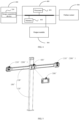
Fig. 4 is a schematic view of an electrical connection principle between the machine vision module, the failure sensor, the output module, and the controller; -
Fig. 5 is a schematic perspective view of a vehicle detection system according to another embodiment of the present invention; -
Fig. 6 is a schematic perspective view of a vehicle detection method according to one of the embodiments of the present invention. - In order that the present invention may be readily understood, a more particular description of the invention will be rendered by reference to specific embodiments and the accompanying drawings. It should be noted that when an element is referred to as being "secured"/"fixed'7"mounted" to another element, it can be directly on the other element or one or more intermediate elements may be present between the elements. When one element is referred to as being "connected" to another element, it can be directly connected to the other element or one or more intermediate elements may be present between the elements. The terms "vertical", "horizontal", "left", "right", "inner", "outer", and the like are used herein for descriptive purposes only.
- Unless defined otherwise, all technical and scientific terms used in the description have the same meaning as commonly understood by one of ordinary skill in the art to which this invention belongs. The terms used in the description of the present invention are for the purpose of describing specific embodiments only and are not intended to be limiting of the present invention. As used in the description, the term "and/or" includes any and all combinations of one or more of the associated listed items.
- Furthermore, the technical features involved in various embodiments of the present invention described below can be combined as long as they do not conflict with each other.
- In this description, "mounting" includes welding, screwing, clamping, gluing, etc. to fix or restrain a certain element or device in a specific position or place. The element or device may either be fixed in a specific position or place, or may be movable within a limited range. The element or device may or may not be detachable after being fixed or restrained in the specific position or place, and is not limited in the embodiments of the present invention.
- Referring now to
Figs. 1-3 , which respectively show a schematic perspective view of a vehicle detection system provided by one of the embodiments of the present invention, a partially enlarged schematic view at A, and a partially enlarged schematic view at B. The vehicle detection system comprises asupport 100, amachine vision module 200, afailure sensor 300, and acontroller 400. Thesupport 100 is used for mounting and supporting various structures such as themachine vision module 200, thefailure sensor 300, and thecontroller 400, etc. Themachine vision module 200 is mounted to thesupport 100 and includes at least oneimage acquisition device 210 that is fixed in position relative to thesupport 100; theimage acquisition device 210 includes animage acquisition sensor 212 for acquiring an image having related parameters of hardware to be detected of a vehicle to be detected (not shown). Thefailure sensor 300 is used for acquiring the position change information of theimage acquisition sensor 212 and outputting a motion parameter signal comprising the position change information. Thecontroller 400 is electrically connected to thefailure sensor 300 for determining whether the position of theimage acquisition sensor 212 needs to be calibrated based on the motion parameter signal output by thefailure sensor 300. It is worth noting that "electrically connected" in this embodiment means that the communication of electrical signals between two structures can be realized either by a wired electrical connection via a cable or by a radio connection via Bluetooth, WiFi module, etc. - With respect to the
support 100 described above, and with particular reference toFig. 1 , abase 110, avertical frame assembly 120, and across beam assembly 130 are included. Thebase 110 includes amain body 112 having an I-shape as a whole and several drivingwheels 113 mounted to the bottom of themain body 112. Thevertical frame assembly 120 is mounted to the top of the main body of thebase 110 and extends in the vertical direction as shown. Mounted to thevertical frame assembly 120 and extending in the illustrated horizontal direction is across beam assembly 130 that is slidingly fitted with thevertical frame assembly 120 along the vertical direction shown in the figure. Thecross beam assembly 130 can be moved or stopped in the illustrated vertical direction in a timely manner driven by an external corresponding driving assembly. - The
machine vision module 200 described above, with particular reference toFigs. 2 and 3 in conjunction withFig. 1 , includes at least twoimage acquisition devices 210 mounted to thecross beam assembly 130 in a fixed position relative to thesupport 100. In the present embodiment, the number of theimage acquisition devices 210 is two, and the twoimage acquisition devices 210 are arranged at intervals on thecross beam assembly 130; it could be understood that in other embodiments of the present invention, the number ofimage acquisition devices 210 may be other numbers, such as one, or three and more. Alternatively, theimage acquisition device 210 is detachably fixed to thecross beam assembly 130 and is switchable between a locked state and an unlocked state; in the locked state, theimage acquisition device 210 is fixed relative to thesupport 100, and in the unlocked state, theimage acquisition device 210 can be adjusted in the position either by a user or a maintenance person manually, or under the action of an external driving mechanism, so as to adapt to the detection requirements of different vehicle types. - The
image acquisition device 210 includes ahousing 211 and animage acquisition sensor 212 mounted to thehousing 211. Thehousing 211 is fixed to thecross beam assembly 130 by means of a detachable connection, and theimage acquisition sensor 212 is mounted on thehousing 211 and has the function of acquiring an external image; in the present embodiment, theimage acquisition sensor 212 is specifically used for acquiring an image having relevant parameters of hardware to be detected of a wheel on a vehicle to be detected, or a target mounted on the vehicle, etc. - With respect to the above-mentioned
failure sensor 300, please continue to refer toFigs. 2 and 3 and at the same time referring toFig. 1 , thefailure sensor 300 is relatively fixed in position with theimage acquisition sensor 212 in theimage acquisition device 210, and is used for detecting the position change information of theimage acquisition sensor 212 and outputting a motion parameter signal having the position change information to thecontroller 400. Alternatively, thefailure sensor 300 comprises at least one of an acceleration sensor, a pressure sensor, and a gyroscope; it could be understood that thefailure sensor 300 is not limited to the selection among the above-described sensors, and may be other sensors as long as it is capable of detecting the position change information of the image acquisition sensor and outputting a motion parameter signal having the position change information. - In some embodiments, the
failure sensor 300 is fixed to thehousing 211. Specifically, in the sameimage acquisition device 210, theimage acquisition sensor 212 is fixed in position with respect to thehousing 211, and thefailure sensor 300 indirectly acquires the position change information of theimage acquisition sensor 212 by detecting the position change information of thehousing 211. Thefailure sensor 300 may be fixed to the outer surface of thehousing 211, or may be integrated into the interior of theimage acquisition device 210, such as the inner surface of thehousing 211 or the internal circuit board of theimage acquisition device 210. - In some embodiments, the
failure sensor 300 is fixed to theimage acquisition sensor 212 and directly detects position change information of theimage acquisition sensor 212. The number ofimage acquisition sensors 212 in the sameimage acquisition device 210 can be one or more, and eachimage acquisition sensor 212 is fixed relative to thehousing 211; or the number of theimage acquisition sensors 212 in the sameimage acquisition device 210 is one or more, and the position of eachimage acquisition sensor 212 relative to thehousing 211 may change such as angular displacement, etc. and at this time, thefailure sensor 300 corresponds to theimage acquisition sensors 212 one-to-one; alternatively, the number of theimage capturing sensors 212 in the sameimage acquisition device 210 is two or more, wherein some of theimage capturing sensors 212 are fixed in position relative to thehousing 211, and the position of some of theimage capturing sensors 212 relative to thehousing 211 can be changed such as angular displacement, etc. and then each image capturing sensor which can be changed in displacement corresponds to afailure sensor 300. - With respect to the
controller 400 described above, and with particular reference toFig. 1 in conjunction withFigs. 2 and 3 , thecontroller 400 is in electrical communication with theimage acquisition device 210 and thefailure sensor 300, respectively. In this embodiment, thecontroller 400 is an independent structure that is mounted to thebase 110 and electrically connected tofailure sensor 300 via thecable 410. It could be understood that in some other embodiments of the present invention, thecontroller 400 may be housed withinvertical frame assembly 120 or thecross beam assembly 130, or integrated within theimage acquisition device 210. Thecontroller 400 is used for receiving an image having relevant parameters of the hardware to be detected collected by theimage acquisition device 210 and parsing the same to obtain a detection result. Thecontroller 400 is also used for receiving the motion parameter signal output by thefailure sensor 300 and determining whether the position of theimage acquisition sensor 212 needs to be calibrated based on the motion parameter signal. Specifically, thecontroller 400 is used for executing a first intervention treatment when the motion parameter signal is greater than a first preset threshold; the first preset threshold is one reference value preset by thecontroller 400 itself, and when the motion parameter signal is higher than the first threshold, the detection precision of the vehicle detection system is seriously disturbed, and the detection result is obviously abnormal. Alternatively, the first intervention treatment comprises: locking the detection function of the vehicle detection system. Then, the user can know that the vehicle detection system is in an unstable state through the first intervention treatment, then correct the vehicle detection system by reasonable means, and then unlock the detection function of the vehicle detection system, so as to avoid a safety accident caused by the vehicle being corrected under the wrong detection precision. - In order to enable a user to, when the detection precision of the vehicle detection system is disturbed and thus affects the detection function, quickly and clearly know the abnormal interference degree of the vehicle detection system through vision and hearing so as to timely correct the vehicle detection system, the vehicle detection system further comprises an
output module 500. Specifically, referring toFig. 1 in conjunction withFigs. 2 and 3 , theoutput module 500 is electrically connected to thecontroller 400 via anothercable 410 for outputting a determination result from thecontroller 400 about whether the position of theimage acquisition sensor 212 needs to be calibrated. In the present embodiment, the first intervention treatment executed by thecontroller 400 further includes: controlling theoutput module 500 to output a first warning signal. Alternatively, theoutput module 500 comprises a display device, and the above-mentioned first warning signal comprises visual information such as an image, characters, numbers, symbols, etc. output by the display device; for example, in some implementation modes, the first alert signal includes the following textual content: "the detection system is abnormal, please calibrate the position of image acquisition sensor in time". Further, alternatively, theoutput module 500 further comprises a sound output device, and the above-mentioned first warning signal further comprises a sound signal output by the sound output device; for example, in some implementation modes, the first warning signal includes the following sound content: "the detection system is abnormal, please calibrate the position of image acquisition sensor in time". Still further, alternatively, theoutput module 500 is a display that includes a display device and a sound output device at the same time. It could be understood that in other embodiments of the invention, the output module may also comprise only any one of a display device and a sound output device. - Further, the controller is used for determining, according to the motion parameter signal, whether the position of the image acquisition sensor needs to be calibrated, comprising: the
controller 400 being used for executing a second intervention treatment when the above-mentioned motion parameter signal is greater than a second pre-set threshold and is less than or equal to the first preset threshold; and for not executing any intervention treatment when the motion parameter signal is less than or equal to the second parameter threshold. The second preset threshold is one value pre-set by thecontroller 400 itself, and is less than the first preset threshold; when the above-mentioned motion parameter signal is greater than the second preset threshold and is less than or equal to the first preset threshold, the detection precision of the vehicle detection system is slightly affected, and the detection result has little difference compared with the actual situation and thus can be used; when the above-mentioned motion parameter signal is less than or equal to the second preset threshold, the detection precision of the vehicle detection system is unaffected or minimally affected without affecting the specific detection function. Alternatively, the second intervention treatment comprises: controlling theoutput module 500 to output a second warning signal. Similar to the first warning signal, the second warning signal may be an image signal output by the display device or a sound signal output by the sound output device, but may also be a signal output by a combination of the display device and the sound output device. When theoutput module 500 outputs the second warning signal, the user can clearly know the degree to which the detection is affected caused by the vehicle detection system subjected to the impact, thereby deciding whether to calibrate the vehicle detection system according to actual requirements. - It should be understood that, even though, according to the present embodiment, the
image acquisition device 210, thefailure sensor 300, thecontroller 400, and theoutput module 500 are structures configured independently, the present invention is not limited thereto. For example, in some other embodiments of the present invention, the number ofcontrollers 400 is the same as that of thefailure sensor 300, acontroller 400 is correspondingly electrically connected to afailure sensor 300, and thecontroller 400 and thefailure sensor 300 are both integrated into the correspondingimage acquisition device 210; as another example, thecontroller 400, thefailure sensor 300, and theoutput module 500 have the same number, acontroller 400 is correspondingly electrically connected to afailure sensor 300 and anoutput module 500, and thecorresponding controller 400,failure sensor 300, and theoutput module 500 are all integrated into the correspondingimage acquisition device 210. - It is worth noting that as central control equipment of the vehicle detection system, the
controller 400, as shown inFig. 4 , includes aprocessor 401 and amemory 402, which may be connected via a bus or otherwise. Theimage acquisition device 210, thefailure sensor 300, and theoutput module 500 in themachine vision module 200 are all connected to a bus. - The
memory 402 is a non-volatile computer-readable storage medium that can be used to store non-volatile software programs, non-volatile computer-executable programs, and modules. Theprocessor 401 executes the steps executed by the controller described above by executing non-volatile software programs, instructions, and modules stored inmemory 402. Thememory 402 may comprise a program storage area and a data storage area. The program storage area may store an operating system and an application program required by at least one function; the data storage area may store data output from theimage acquisition device 210, the image processor, thefailure sensor 300, and the like. In addition, thememory 402 may include high speed random access memory and may also include non-volatile memory, such as at least one disc memory device, flash memory device, or other non-volatile solid state memory device. - In some embodiments, the
memory 402 may alternatively include a memory remotely provided with respect to theprocessor 401. The remote memory may be connected to theprocessor 401 via a network. Examples of such networks include, but are not limited to, the Internet, intranets, local area networks, mobile communication networks, and combinations thereof. - The program instructions/modules are stored in the
memory 402 and, when executed by one ormore processors 401, execute the steps executed by the controller described above. - Furthermore, when the vehicle detection system is applied to the four-wheel positioning of a vehicle, one of the
image acquisition devices 210 is used for acquiring an image having relevant parameters of a left front wheel and a left rear wheel of the vehicle to be detected, and the otherimage acquisition device 210 is used for acquiring an image having relevant parameters of a right front wheel and a right rear wheel of the vehicle to be detected. In order to facilitate establishing the relationship between the relevant parameters respectively acquired by the twoimage acquisition devices 210, themachine vision module 200 further comprises an associatedimage acquisition device 220 and an associatedtarget 230. Specifically, in conjunction withFigs. 1-3 , the associatedimage acquisition device 220 is fixed to one of the twoimage acquisition devices 210 and is electrically connected to thecontroller 400, and the associatedtarget 230 is fixed to the other of the two image acquisition devices. The associatedimage acquisition device 220 is used for acquiring the position information about the associatedtarget 230 relative to itself so as to establish a mutual position relationship between the twoimage acquisition devices 210, and then obtaining the relation between the positional relationship between the left front wheel, the left rear wheel, the rear front wheel, and the right rear wheel of the vehicle to be detected, and other relevant parameters. Alternatively, the associated target is a planar target. - Alternatively, the
failure sensor 300 is built into the associatedimage acquisition device 220 and the associatedtarget 230. Specifically, afailure sensor 300 is built into the associatedimage acquisition device 220 and afailure sensor 300 is built into the associatedtarget 230. Further, considering that theimage acquisition device 210 directly acquires the image with a wheel to obtain the relevant parameters of the wheel, a relatively rigorous and precise algorithm is required to realize the analysis of the wheel parameters. To overcome this drawback, the vehicle detection system also includes a target to be detected (not shown). Specifically, the target to be detected is used for being mounted on a wheel of a vehicle to be detected, theimage acquisition device 210 is used for acquiring an image of the target to be detected, theimage acquisition device 210 can identify the target to be detected more simply than directly identifying the wheel itself, and the controller can calculate relevant parameters of the wheel from the position of the target to be detected in the image and analyze the detection result. - Further, the
machine vision module 200 further comprises an image processor (not shown), which is electrically connected to theimage acquisition device 210 and thecontroller 400 respectively, and is used for receiving an image having the relevant parameters of the hardware to be detected acquired by twoimage acquisition devices 210 and an image having the associatedtarget 230 acquired by the associatedimage acquisition device 220 and performing optimization treatments such as noise reduction, etc. so as to improve the rate and accuracy of the analysis by thecontroller 400. Alternatively, the image processor and thecontroller 400 are integrally provided; it could be understood that in other embodiments of the present invention, the image processor may also be provided independently from thecontroller 400 or integrated within theimage acquisition device 210. - An embodiment of the present invention provides a vehicle detection system that includes a
support 100, amachine vision module 200, afailure sensing module 300, and acontroller 400. Themachine vision module 200 comprises at least oneimage acquisition device 210 comprising animage acquisition sensor 212 for acquiring relevant parameters of the hardware to be detected on the vehicle. Thefailure sensor 300 is used to acquire the position change information of theimage acquisition sensor 212, and outputs a motion parameter signal including the position change information to thecontroller 400. Thecontroller 400 is electrically connected to thefailure sensor 300, and is used for determining whether the position of the image acquisition sensor needs to be calibrated according to the motion parameter signal, so as to avoid a miscorrection caused by detecting and correcting the vehicle without precalibration after the detection precision of the vehicle detection system is significantly reduced, thereby avoiding the occurrence of dangerous accidents. - In addition, the vehicle detection system further comprises an
output module 500. The vehicle detection system can lock the detection function of the vehicle detection system according to the degree of impact on theimage acquisition sensor 212 and the degree of reduced detection precision, so as to warn a user to correct the vehicle detection system in time; it is also possible to output different warning signals or no warning signal through theoutput module 500, so that the user can know the affected degree of the detection precision of the vehicle detection system in time, thereby prompting the user to correct the vehicle detection system in time. - Based on the same inventive concept, the present invention also provides another vehicle detection system. With particular reference to
Fig. 5 , there is shown a schematic perspective view of a vehicle detection system in the present embodiment, including a support 100', a machine vision module 200', a failure sensor (not shown), a controller 400', and an output module 500'. Among other things, the support 100' includes a vertical frame assembly 120' and a cross beam assembly 130'. The cross beam assembly 130' is fixed to the vertical frame assembly 120'. The machine vision module 200' includes at least one image acquisition device 210' mounted to the cross beam assembly 130'. The failure sensor is built into the image acquisition device 210'. The controller 400' is mounted to the cross beam assembly 130'. Theoutput module 500 is a mobile terminal such as a mobile phone, a tablet, etc. and is electrically connected to thecontroller 400 in a wireless communication manner. - In order to facilitate the distinction from the vehicle detection system in the first embodiment, the vehicle detection system in the first embodiment is hereinafter referred to as a first vehicle detection system, and similarly, the vehicle detection system in the present embodiment is referred to as a second vehicle detection system. With reference to
Figs. 1 to 5 , the second vehicle detection system and the first vehicle detection system have substantially the same structural composition, and the two differ from each other mainly in that: - the
support 100 in the first vehicle detection system comprises abase 110, avertical frame assembly 120, and across beam assembly 130, wherein thebase 110 comprises adriving wheel 111 so that the first vehicle detection system can move flexibly in the whole detection process, and is suitable for four-wheel positioning of a vehicle to be detected or the calibration of hardware in ADAS; theoutput module 500 is connected to thecontroller 400 via acable 410; - the support 100' in the second vehicle detection system only comprises a vertical frame assembly 120' and a cross beam assembly 130', wherein the bottom of the vertical frame assembly 120' is used for fixing to a workbench or the ground during the detection so that the second vehicle detection system is suitable for four-wheel positioning of a vehicle to be detected; the output module 500' is wirelessly connected to the controller 400'.
- It can be seen therefrom that the scope of application of the first vehicle detection system is wide, and the scope of application of the second vehicle detection system is narrow; however, since the output module 500' is a mobile terminal, a user can be away from structures such as the support 100' during use, which has the advantages of convenience and safety.
- Based on the same inventive concept, the present invention also provides a vehicle detection method, which is applied to the vehicle detection system in any of the above-described embodiments. Referring to
Fig. 6 , which is a schematic flow chart of the vehicle detection method, and in conjunction withFigs. 1 to 3 , the vehicle detection method comprises the steps of - S 1: in controlling the
image acquisition device 210 to detect the vehicle to be detected, receiving a motion parameter signal including the position change information of theimage acquisition sensor 212 sent from thefailure sensor 300. Specifically, thecontroller 400 is connected to theimage acquisition device 210 and thefailure sensor 300, respectively; in the process that thecontroller 400 controls theimage acquisition device 210 to acquire relevant parameters of the vehicle, thefailure sensor 300 acquires the position change information of theimage acquisition sensor 212, and outputs a motion parameter signal including the position change information to thecontroller 400. - S2: according to the motion parameter signal, determining whether the position of the
image acquisition sensor 212 needs to be calibrated, and if so, executing an intervention treatment. Specifically, thecontroller 400 acquires the motion parameter signal output by thefailure sensor 300, and compares the motion parameter signal with an internal preset threshold thereof to determine whether calibration is required; if the calibration is required, thecontroller 400 performs an intervention treatment, and if not, no intervention treatment is performed. More specifically, thecontroller 400 is preset with a first preset threshold and a second preset threshold; when the above-mentioned motion parameter signal is greater than the first preset threshold, the detection precision of the vehicle detection system is seriously affected, and thecontroller 400 executes a first intervention treatment; when the above-mentioned motion parameter signal is greater than the second preset threshold and less than or equal to the first preset threshold, the detection precision of the vehicle detection system is slightly affected, and the controller performs a second intervention treatment; when the motion parameter signal is less than or equal to the second parameter threshold, the detection precision of the vehicle detection system is minimally affected or unaffected, and thecontroller 400 does not perform any intervention treatment. - Alternatively, the first intervention treatment comprises: a detection function that locks the vehicle detection system; then, the user may be alerted to correct the vehicle detection system in time. Alternatively, the first intervention treatment further comprises: controlling the output module to output a first warning signal; according to the difference in the actual structure of the
output module 500, it being the scenario that the first warning signal may be visual information such as images, characters, symbols, etc. and may also be audible information such as sounds, etc.; then, after acquiring the first warning signal, it being possible that the user corrects the vehicle detection system in time to ensure an accurate detection result. It could be understood that, in some embodiments, the first intervention treatment described above may also include only one of the two approaches described above. - Alternatively, the second intervention treatment comprises steps as follows: the
controller 400 controls theoutput module 500 to output a second warning signal; according to the different actual structures of theoutput module 500, the second warning signal can be visual information such as images, characters, symbols, etc. and can also be audible information such as sounds, etc.; then, after acquiring the second warning signal, the user can correct the vehicle detection system in time to ensure a more accurate detection result. - The vehicle detection method provided by an embodiment of the present invention is used in the detection process of a vehicle to be detected by a vehicle detection system. Since the
controller 400 can acquire the position change information about theimage acquisition sensor 212 in theimage acquisition device 210 in real time via thefailure sensor 300, that is to say, thecontroller 400 can make matching intervention treatment or no intervention treatment according to the position change information about theimage acquisition sensor 212 in real time, it is ensured that the vehicle detection system performs a detection process only when the detection precision is good, so as to obtain a reasonable detection result. Therefore, safety accidents caused by the vehicle hardware miscorrection based on the abnormal detection result are avoided. - Based on the same inventive concept, an embodiment of the present invention also provides a non-volatile computer storage medium having stored thereon computer-executable instructions that, when executed by one or more processors, such as one
processor 401 inFig. 4 , may cause the one or more processors to execute the steps executed by the controller described above. - Based on the same inventive concept, an embodiment of the present invention also provides a computer program product comprising a computer program stored on a non-volatile computer readable storage medium, the computer program comprising a program instruction that, when executed by the electronic equipment, causes the electronic equipment to execute the steps executed by the controller described above.
- Finally, it should be noted that: the above embodiments are merely illustrative of the technical solutions of the present invention, rather than limiting thereto; combinations of technical features in the above embodiments or in different embodiments are also possible within the idea of the present invention, and the steps can be implemented in any order, and there are many other variations of the different aspects of the present invention as described above, which are not provided in detail for the sake of brevity; although the present invention has been described in detail with reference to the foregoing embodiments, those of ordinary skills in the art will appreciate that: the technical solutions disclosed in the above-mentioned embodiments can still be modified, or some of the technical features can be replaced by equivalents; such modifications and substitutions do not depart the essence of corresponding technical solutions from the scope of the technical solutions of various embodiments of the present invention.
Claims (23)
- A vehicle detection system characterized by comprising:a support;a machine vision module mounted to the support, wherein the machine vision module comprises at least one image acquisition device, a position of the image acquisition device relative to the support is fixed, and the image acquisition device comprises an image acquisition sensor for acquiring an image having relevant parameters of hardware to be detected on a vehicle;a failure sensor for acquiring position change information about the image acquisition sensor and outputting a motion parameter signal comprising the position change information;and a controller electrically connected to the failure sensor for determining whether the position of the image acquisition sensor needs to be calibrated according to the motion parameter signal.
- The vehicle detection system according to claim 1, characterized in that the failure sensor is fixed to the image acquisition sensor.
- The vehicle detection system according to claim 2, characterized in that the failure sensor is integrated within the image acquisition device.
- The vehicle detection system according to claim 1, characterized in that the failure sensor comprises at least one of an acceleration sensor, a pressure sensor, and a gyroscope.
- The vehicle detection system according to claim 1, characterized in that the support comprises:a base, a bottom of the base comprising a driving wheel;a vertical frame assembly mounted to the base and extending in a vertical direction; anda cross beam assembly mounted to the vertical frame assembly, the cross beam assembly andthe vertical frame assembly slidingly fit in the vertical direction, and the image acquisition device being mounted to the cross beam assembly.
- The vehicle detection system according to claim 1, characterized in that the support comprises a vertical frame assembly and a cross beam assembly;
the cross beam assembly is mounted to the vertical frame assembly, the cross beam assembly and the vertical frame assembly are slidingly fit in the vertical direction, and the image acquisition device is mounted to the cross beam assembly. - The vehicle detection system according to claim 5 or 6, characterized in that the machine vision module comprises two of the image acquisition devices provided at intervals on the cross beam assembly;
the controller is housed within the vertical frame assembly or the cross beam assembly. - The vehicle detection system according to claim 1, characterized by further comprising an associated image acquisition device and an associated target;
wherein the machine vision module comprises two image acquisition devices, the associated image acquisition device is fixed to one of the two image acquisition devices and is electrically connected to the controller, the associated target is fixed to the other one of the two image acquisition devices, the associated image acquisition device is used for acquiring position information about the associated target relative to the associated image acquisition device, and the associated target is a planar target. - The vehicle detection system according to claim 1, characterized in that one image acquisition device comprises at least two image acquisition sensors, the failure sensor being fixed to the image acquisition sensor and one image acquisition sensor corresponding to one failure sensor.
- The vehicle detection system according to claim 1, characterized in that the machine vision module further comprises an image processor, the image processor being electrically connected to the image acquisition sensor and the controller, respectively, the image processor being used for optimizing the image acquired by the image acquisition sensor, and the image processor being integrally provided with the controller.
- The vehicle detection system according to claim 1, characterized by further comprising an output module electrically connected to the controller, wherein the output module is used for outputting a determination result of the controller;
and the output module comprises a display device and/or a sound output device. - The vehicle detection system according to claim 1, characterized by further comprising a target to be detected, the target to be detected being used for being mounted to a wheel and the image acquisition device being used for acquiring an image of the target to be detected.
- The vehicle detection system according to claim 11, characterized in that the controller is used for determining whether the position of the image acquisition sensor needs to be calibrated according to the motion parameter signal, comprising:
the controller being used for executing a first intervention treatment when the motion parameter signal is greater than a first preset threshold. - The vehicle detection system according to claim 13, characterized in that the first intervention treatment comprises: locking a detection function of the vehicle detection system; and/or the first intervention treatment comprises: controlling the output module to output a first warning signal.
- The vehicle detection system according to claim 13, characterized in that the controller is used for determining whether the position of the image acquisition sensor needs to be calibrated according to the motion parameter signal, comprising:
the controller being used for executing a second intervention treatment when the motion parameter signal is greater than a second preset threshold and less than or equal to the first preset threshold. - The vehicle detection system according to claim 15, characterized in that the second intervention treatment comprises: controlling the output module to output a second warning signal.
- The vehicle detection system according to claim 11, characterized in that the number of the controllers is the same as that of the failure sensors, one controller being correspondingly electrically connected to one failure sensor, and both the controller and the failure sensor being integrated into a corresponding image acquisition device.
- The vehicle detection system according to claim 17, characterized by further comprising an output module, wherein the output module corresponds to the image acquisition device in a one-to-one correspondence, the output module is integrated into a corresponding image acquisition device and electrically connected to the controller, and the output module is used to output the determination result of the controller.
- A vehicle detection method applied to the vehicle detection system according to any one of claims 1 to 18, characterized in that the method comprises steps of:receiving a motion parameter signal comprising position change information of the image acquisition sensor sent by the failure sensor while controlling the image acquisition device to detect the vehicle;and determining whether the position of the image acquisition sensor needs to be calibrated according to the motion parameter signal, and if so, executing an intervention treatment.
- The vehicle detection method according to claim 19, characterized in that determining whether the position of the image acquisition sensor needs to be calibrated, and if so, executing an intervention treatment, comprise:
executing a first intervention treatment when the motion parameter signal is greater than a first preset threshold. - The vehicle detection method according to claim 20, characterized in that the vehicle detection system further comprises an output module electrically connected to the controller; the first intervention treatment comprises: locking a detection function of the vehicle detection system;
and/or the first intervention treatment comprises: controlling the output module to output a first warning signal. - The vehicle detection method according to claim 21, characterized in that determining whether the position of the image acquisition sensor needs to be calibrated, and if so, executing an intervention treatment, further comprise:
executing a second intervention treatment when the motion parameter signal is greater than a second preset threshold and less than or equal to the first preset threshold. - The vehicle detection method according to claim 22, characterized in that the second intervention treatment comprises: controlling the output module to output a second warning signal.
Applications Claiming Priority (2)
| Application Number | Priority Date | Filing Date | Title |
|---|---|---|---|
| CN202010567583.1A CN111599036B (en) | 2020-06-19 | 2020-06-19 | Vehicle detection system and vehicle detection method |
| PCT/CN2021/100795 WO2021254468A1 (en) | 2020-06-19 | 2021-06-18 | Vehicle detection system and vehicle detection method |
Publications (2)
| Publication Number | Publication Date |
|---|---|
| EP4170313A1 true EP4170313A1 (en) | 2023-04-26 |
| EP4170313A4 EP4170313A4 (en) | 2023-12-06 |
Family
ID=72188090
Family Applications (1)
| Application Number | Title | Priority Date | Filing Date |
|---|---|---|---|
| EP21826059.4A Pending EP4170313A4 (en) | 2020-06-19 | 2021-06-18 | Vehicle detection system and vehicle detection method |
Country Status (4)
| Country | Link |
|---|---|
| US (1) | US20230124731A1 (en) |
| EP (1) | EP4170313A4 (en) |
| CN (1) | CN111599036B (en) |
| WO (1) | WO2021254468A1 (en) |
Families Citing this family (10)
| Publication number | Priority date | Publication date | Assignee | Title |
|---|---|---|---|---|
| CN111599036B (en) * | 2020-06-19 | 2023-06-23 | 深圳市道通科技股份有限公司 | Vehicle detection system and vehicle detection method |
| WO2022140929A1 (en) * | 2020-12-28 | 2022-07-07 | 深圳市大疆创新科技有限公司 | Automatic driving visual calibration device |
| CN112945571B (en) * | 2021-01-26 | 2023-07-07 | 深圳市道通科技股份有限公司 | Same-screen display method and device and vehicle measurement system |
| USD1000969S1 (en) * | 2021-06-10 | 2023-10-10 | Autel Intelligent Technology Corp., Ltd. | Calibration device |
| USD1000988S1 (en) * | 2021-06-10 | 2023-10-10 | Autel Intelligent Technology Corp., Ltd. | Calibration device |
| CN215338924U (en) * | 2021-07-07 | 2021-12-28 | 深圳市道通科技股份有限公司 | Calibration support |
| USD1000970S1 (en) * | 2022-01-24 | 2023-10-10 | Autel Intelligent Technology Corp., Ltd. | Calibration device |
| USD1000971S1 (en) * | 2022-03-10 | 2023-10-10 | Autel Intelligent Technology Corp., Ltd. | Calibration device |
| USD1000972S1 (en) * | 2022-03-10 | 2023-10-10 | Autel Intelligent Technology Corp., Ltd. | Calibration device |
| CN115589534B (en) * | 2022-09-09 | 2023-09-08 | 广州市斯睿特智能科技有限公司 | Following type vehicle detection item picture acquisition device and method |
Family Cites Families (19)
| Publication number | Priority date | Publication date | Assignee | Title |
|---|---|---|---|---|
| EP1309832B1 (en) * | 2000-08-14 | 2008-10-22 | Snap-on Incorporated | Self-calibrating 3D machine measuring system useful in motor vehicle wheel alignment |
| US7855783B2 (en) * | 2007-09-18 | 2010-12-21 | Snap-On Incorporated | Integrated circuit image sensor for wheel alignment systems |
| KR101367778B1 (en) * | 2012-11-29 | 2014-03-28 | 위드로봇 주식회사 | Vehicle alignment system performing relative camera position calibration and providing method thereof |
| CN202994480U (en) * | 2012-12-10 | 2013-06-12 | 上海一成汽车检测设备科技有限公司 | 3D four-wheel aligner provided with large LED screen |
| CN203176673U (en) * | 2013-04-07 | 2013-09-04 | 深圳市三杰宜科技有限公司 | Automatic lifting device and four-wheel positioning instrument with automatic lifting device |
| US9644782B2 (en) * | 2013-10-23 | 2017-05-09 | Hunter Engineering Company | Wheel alignment system cabinet structure |
| EP3332210A4 (en) * | 2015-10-06 | 2019-05-08 | Snap-On Incorporated | Wheel aligner with advanced diagnostics and no-stop positioning |
| CN107124532A (en) * | 2016-02-25 | 2017-09-01 | 实耐宝公司 | Four-wheel position finder and its electronic system, Central Processing Board and camera board |
| CN205579077U (en) * | 2016-03-04 | 2016-09-14 | 赵东 | Lifting device for four -wheel aligner |
| EP3472555B1 (en) * | 2016-08-16 | 2021-05-19 | Snap-On Incorporated | Vehicle wheel alignment method and system |
| US10788400B2 (en) * | 2016-10-11 | 2020-09-29 | Hunter Engineering Company | Method and apparatus for vehicle inspection and safety system calibration using projected images |
| CN207095542U (en) * | 2017-08-14 | 2018-03-13 | 山东团尚网络科技股份有限公司 | A kind of vehicular four wheels position indicator calibrating installation |
| CN207991830U (en) * | 2018-03-21 | 2018-10-19 | 上海邦田交通科技有限公司 | A kind of automobile four-wheel positioning system |
| US11145084B2 (en) * | 2018-08-30 | 2021-10-12 | Hunter Engineering Company | Method and apparatus for guiding placement of ADAS fixtures during vehicle inspection and service |
| CN109827784A (en) * | 2018-11-29 | 2019-05-31 | 深圳市元征科技股份有限公司 | A kind of work state monitoring method and device of four-wheel position finder |
| CN210462329U (en) * | 2019-07-01 | 2020-05-05 | 深圳嘉车科技有限公司 | Lifting device of four-wheel aligner |
| CN210221507U (en) * | 2019-07-01 | 2020-03-31 | 深圳嘉车科技有限公司 | Two-column four-wheel positioning instrument |
| CN210689549U (en) * | 2019-12-06 | 2020-06-05 | 安徽省爱夫卡电子科技有限公司 | 3D four-wheel positioning device |
| CN111599036B (en) * | 2020-06-19 | 2023-06-23 | 深圳市道通科技股份有限公司 | Vehicle detection system and vehicle detection method |
-
2020
- 2020-06-19 CN CN202010567583.1A patent/CN111599036B/en active Active
-
2021
- 2021-06-18 EP EP21826059.4A patent/EP4170313A4/en active Pending
- 2021-06-18 WO PCT/CN2021/100795 patent/WO2021254468A1/en unknown
-
2022
- 2022-12-18 US US18/067,716 patent/US20230124731A1/en active Pending
Also Published As
| Publication number | Publication date |
|---|---|
| US20230124731A1 (en) | 2023-04-20 |
| WO2021254468A1 (en) | 2021-12-23 |
| CN111599036B (en) | 2023-06-23 |
| CN111599036A (en) | 2020-08-28 |
| EP4170313A4 (en) | 2023-12-06 |
Similar Documents
| Publication | Publication Date | Title |
|---|---|---|
| EP4170313A1 (en) | Vehicle detection system and vehicle detection method | |
| US11796657B2 (en) | Control device, control method, program, and storage medium | |
| US20150217696A1 (en) | Automobile blind spot detection system and method | |
| US20120259499A1 (en) | Vehicle state detecting device and vehicle state detecting system | |
| EP3336488B1 (en) | Method of verification of the installation of an apparatus mounted on board a vehicle, and related system | |
| WO2016113814A1 (en) | In-vehicle unit | |
| US10586348B2 (en) | Distance measurement device and image capturing control device | |
| CN112881989A (en) | Self-calibration method of millimeter wave radar on vehicle, electronic device and storage medium | |
| CN110140062A (en) | Method for running vehicle driver assistance system | |
| US11654939B2 (en) | Autonomous driving apparatus and method that outputs different warnings based on driving risk | |
| CN112066915B (en) | Wheel positioning system and vehicle measurement system | |
| US9956833B2 (en) | In-vehicle reporting apparatus and reporting system | |
| CN112363130A (en) | Vehicle-mounted sensor calibration method, storage medium and system | |
| US20110238263A1 (en) | Preventing condensation on the surface of moving vehicles | |
| CN105984288B (en) | The code method of radio tire pressure monitoring system | |
| US20220327671A1 (en) | Error-Robust Capture of Vehicle Surroundings | |
| JP2016225719A (en) | Stereo camera device, vehicle, and calibration method | |
| KR20150024541A (en) | Apparatus and method for smart parking assist having inspection mode providing part | |
| JP2009208561A (en) | Driver photographing system and driver photographing method | |
| JPWO2016042951A1 (en) | Position detection system | |
| JP2009051473A (en) | Parking assistant system | |
| US20200217929A1 (en) | Detecting misalignment | |
| KR101743652B1 (en) | Method of auto location using multi sensing tilt sensor and tire pressure monitoring system thereof | |
| US20170115132A1 (en) | Vehicle terminal | |
| KR20170094423A (en) | Camera system and method for operating a camera system |
Legal Events
| Date | Code | Title | Description |
|---|---|---|---|
| STAA | Information on the status of an ep patent application or granted ep patent |
Free format text: STATUS: THE INTERNATIONAL PUBLICATION HAS BEEN MADE |
|
| PUAI | Public reference made under article 153(3) epc to a published international application that has entered the european phase |
Free format text: ORIGINAL CODE: 0009012 |
|
| STAA | Information on the status of an ep patent application or granted ep patent |
Free format text: STATUS: REQUEST FOR EXAMINATION WAS MADE |
|
| 17P | Request for examination filed |
Effective date: 20230117 |
|
| AK | Designated contracting states |
Kind code of ref document: A1 Designated state(s): AL AT BE BG CH CY CZ DE DK EE ES FI FR GB GR HR HU IE IS IT LI LT LU LV MC MK MT NL NO PL PT RO RS SE SI SK SM TR |
|
| DAV | Request for validation of the european patent (deleted) | ||
| DAX | Request for extension of the european patent (deleted) | ||
| A4 | Supplementary search report drawn up and despatched |
Effective date: 20231103 |
|
| RIC1 | Information provided on ipc code assigned before grant |
Ipc: G01B 11/275 20060101ALI20231027BHEP Ipc: G01M 17/013 20060101AFI20231027BHEP |