EP4170299A1 - Method of estimating the mass of a moving vehicle, corresponding system and computer program product - Google Patents
Method of estimating the mass of a moving vehicle, corresponding system and computer program product Download PDFInfo
- Publication number
- EP4170299A1 EP4170299A1 EP22201810.3A EP22201810A EP4170299A1 EP 4170299 A1 EP4170299 A1 EP 4170299A1 EP 22201810 A EP22201810 A EP 22201810A EP 4170299 A1 EP4170299 A1 EP 4170299A1
- Authority
- EP
- European Patent Office
- Prior art keywords
- vehicle
- values
- mass
- value
- est
- Prior art date
- Legal status (The legal status is an assumption and is not a legal conclusion. Google has not performed a legal analysis and makes no representation as to the accuracy of the status listed.)
- Granted
Links
Images


Classifications
-
- G—PHYSICS
- G01—MEASURING; TESTING
- G01G—WEIGHING
- G01G19/00—Weighing apparatus or methods adapted for special purposes not provided for in the preceding groups
- G01G19/08—Weighing apparatus or methods adapted for special purposes not provided for in the preceding groups for incorporation in vehicles
- G01G19/086—Weighing apparatus or methods adapted for special purposes not provided for in the preceding groups for incorporation in vehicles wherein the vehicle mass is dynamically estimated
Definitions
- the present invention relates to methods for estimating the mass of a moving vehicle, and to corresponding electronic systems and computer program products.
- the invention relates to a method in which the mass of the vehicle is estimated as a function of the values of one or more parameters indicative of the dynamic state of the vehicle, sensed during a sampling interval whilst the vehicle is moving and its dynamic state meets a given condition of acceleration.
- the object of one or more embodiments is to provide a method for estimating the mass of a moving vehicle that is robust in regard to the variability of the driving conditions and that produces a precise estimate of the mass of the vehicle.
- One or more embodiments may refer to a corresponding electronic system, which can be mounted on board a vehicle.
- One or more embodiments may refer to a corresponding computer program product that can be loaded into the memory of at least one processing circuit (e.g., an electronic control unit or ECU of a vehicle) and comprises software code portions for carrying out the steps of the method when the product is run on the at least one processing circuit.
- at least one processing circuit e.g., an electronic control unit or ECU of a vehicle
- software code portions for carrying out the steps of the method when the product is run on the at least one processing circuit.
- reference to such a computer program product is understood as being equivalent to reference to a computer-readable means containing instructions for controlling the processing system in order to co-ordinate implementation of the method according to one or more embodiments.
- references to "at least one" processing circuit is intended to highlight the possibility of one or more embodiments being implemented in modular and/or distributed form: for example, one or more embodiments may envisage interaction between a number of electronic control units of the vehicle, such as units for sensing data (using sensors) and data-processing units.
- one or more embodiments refer to a method for estimating the mass of a moving vehicle, comprising the following steps:
- the method according to the invention is robust in regard to the variability of the driving conditions and produces a precise estimate of the mass of the vehicle.
- the method comprises repeating steps vi) and vii). At each repetition of step vi) the value of the presumed mass of the vehicle is varied in a second interval comprising M discrete ordered values.
- the second interval is centered around the value of mass selected in the previous execution of step vii), and preferably has a width equal to twice the difference between two consecutive ordered values of said first interval.
- the method comprises:
- the method comprises:
- the method comprises iteratively repeating steps vi), vii), viii), ix), x) and xi), using at each iteration, as values of presumed mass of the vehicle, presumed difference between the sensed angle of longitudinal inclination and the real angle of longitudinal inclination, and presumed force of rolling resistance of the vehicle, the respective values computed at the previous iteration.
- the method comprises:
- the method comprises:
- the method comprises:
- the method comprises estimating the transmission ratio between the engine and the drive wheels of the vehicle as a function of a lowpass-filtered ratio between a sensed rotational speed of the engine and the speed of the vehicle.
- said error parameter is computed as a function of the sum of the squared errors between the values of sampled speed of the vehicle and the corresponding values of estimated speed of the vehicle.
- the method comprises:
- the method comprises:
- the at least one first parameter indicative of the dynamic state of the vehicle further comprises at least one parameter selected from among:
- determining whether the dynamic state of the vehicle meets said given condition further comprises at least one of the following:
- an electronic system for estimating the mass of a moving vehicle comprises at least one first sensor configured to sense at least one first parameter indicative of the dynamic state of the vehicle, at least one second sensor configured for sensing a plurality of second parameters indicative of the dynamic state of the vehicle, and an electronic control unit configured to carry out the steps of the method according to one or more embodiments.
- Figure 1 is a block diagram of an electronic system 1 configured to implement a method for estimating the mass of a moving vehicle, when the transmission of the vehicle is engaged, via execution of an estimation algorithm.
- the system 1 comprises an enabling module 10 configured to sense one or more parameters indicative of the dynamic state of the vehicle (for example, by receiving one or more messages from a CAN - Controller Area Network - of the vehicle, where each message comprises one or more signals, i.e., the values of one or more parameters) and process the values of the sensed parameters in order to determine, as a function thereof, whether the dynamic state of the vehicle meets a given condition of acceleration.
- an enabling module 10 configured to sense one or more parameters indicative of the dynamic state of the vehicle (for example, by receiving one or more messages from a CAN - Controller Area Network - of the vehicle, where each message comprises one or more signals, i.e., the values of one or more parameters) and process the values of the sensed parameters in order to determine, as a function thereof, whether the dynamic state of the vehicle meets a given condition of acceleration.
- the enabling module 10 receives from the message ERC1 a signal ERC1_DR_ActRetPcTrq indicative of the fact that a retarder device of the transmission is activated, from the message ERC1 a signal ERC1_ER_ActRetPcTrq indicative of the fact that a retarder device of the engine is activated, from the message ETC2 a signal ETC2_TransmCurGear indicative of the gear currently engaged, from the message EBC1 a signal EBC1_EbsBrkSw indicative of the fact that an EBS (Electronic Braking System) is activated, from the message EBC2 a signal EBC2_FA_speed indicative of the travel speed of the vehicle (sensed by one or more sensors mounted on the axle shafts of one or more wheels), and from the message ETC1 a signal ETC1_TransmShiftInProc indicative of the fact that a gear change is in progress.
- EBS Electro Braking System
- the enabling module 10 is configured to process the signals received (some of which are listed above purely by way of non-limiting example) and determine whether the dynamic state of the vehicle meets the condition of acceleration necessary for proper estimation of the mass.
- the conditions to be met may be one or more of the following:
- the acceleration can be computed as a function of the speed signal EBC2_FA_speed.
- the enabling module 10 asserts an enable signal EN (for example, it sets it at the high logic value) to signal that the vehicle is in a dynamic condition suitable for starting the sampling of the data necessary for estimating the mass (for example, when the acceleration of the vehicle is higher than a given threshold).
- the enable signal EN is received in a data-acquisition module 12.
- the enabling module 10 may be configured for verifying whether the absolute value of the (longitudinal) acceleration a v of the vehicle is higher than the respective minimum threshold a V,TH :
- the data-acquisition module 12 is configured to sample and store the ordered sequences of values of a plurality of parameters of the vehicle, during a sampling interval, in response to the fact that the signal EN is asserted.
- the duration of the sampling interval may be fixed or else configurable, and may for example be in the region of some seconds, such as 2 seconds, 5 seconds, or 10 seconds.
- the plurality of parameters sensed by the data-acquisition module 12 comprises the speed of the vehicle, the (net) torque delivered by the engine of the vehicle, the angle of longitudinal inclination of the vehicle with respect to the horizontal, and the coefficient k, i.e., the transmission ratio between the crankshaft and the drive wheels.
- the (net) torque delivered by the engine of the vehicle may be computed by the module 12 as the torque indicated by the engine decreased by the losses due to the parasitic effects of the engine and to frictional factors of the engine.
- the data-acquisition module 12 receives (for example from the CAN) from the message EEC1 a signal EEC1_EngSpeed indicative of the rotational speed of the crankshaft, from the message EC1 a signal EC1_EngRefTrq indicative of a reference engine torque (expressed in Nm) for all the positive torques expressed as percentages, from the message EBC2 a signal EBC2_FA_speed indicative of the travel speed of the vehicle, from the message EEC2 a signal EEC2_ActEngPcTrq indicative of an engine torque (expressed as a percentage with respect to the reference torque EC1_EngRefTrq ), from the message EEC3 a signal EEC3_NomFrictPcTrq indicative of a nominal negative torque (expressed as a percentage with respect to the reference torque EC1_EngRefTrq ) due to friction and/or other loads internal to the engine, from the message EEC3 a signal E
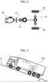
- the chain of transmission of motion of a vehicle may be represented schematically by an engine 20 having an output shaft coupled to the first disk of a clutch 22.
- the second disk of the clutch 22 is coupled to the input shaft of a gearbox 24.
- the output shaft of the gearbox 24 is connected to a differential device 26 arranged in the axle of the drive wheels.
- Two output shafts of the differential device 26 i.e., the axle shafts
- the transmission ratio of the gearbox 24 is designated by g r
- the transmission ratio of the differential 26 is designated by a r
- the radius of the drive wheels 28 is designated by r.
- the module for computing the transmission ratio 14 receives (for example, from the CAN) the signals ETC2_TransmCurGear , ETC1_TransmShiftInProc , EEC1_EngSpeed already described previously, as well as from the message TCO1 a signal TCO1_TcoOutSpeed indicative of the rotational speed of the output shaft of the gearbox and a signal TCO1_TcoVehSpeed indicative of the speed of the vehicle sensed by the tachograph, and processes these signals to determine the value of the coefficient k.
- the data-acquisition module 12 can store in a memory area 16 (for example, a buffer) a vector v[] comprising the sensed samples of the speed of the vehicle, a vector T[] comprising the sensed samples of the (net) torque delivered by the engine, a vector a[] comprising the sensed samples of the angle of longitudinal inclination of the vehicle, and a vector k[] comprising the computed samples of the coefficient k.
- a memory area 16 for example, a buffer
- a vector v[] comprising the sensed samples of the speed of the vehicle
- T[] comprising the sensed samples of the (net) torque delivered by the engine
- a vector a[] comprising the sensed samples of the angle of longitudinal inclination of the vehicle
- a vector k[] comprising the computed samples of the coefficient k.
- the vectors v[], T[], a[] and k[] are not filled (i.e., the data are not sampled and are not stored in the memory area 16).
- the first value of the vector k[] can be set at a default value (for example, -1) to indicate to the estimation module 18 that it must set the value of the estimated speed at the sensed (or real) value of speed. If the enable signal EN is de-asserted before the memory buffer 16 is completely filled with sampled data, sampling of the data can be resumed to fill the memory buffer 16 when the signal EN is asserted again.
- the vectors v[], T[], ⁇ [], and k[] stored in the memory buffer 16 may comprise values corresponding to a plurality of separate time segments.
- the value of the vector k[] stored at each start of a new sampling time segment can be set at the default value (for example, -1) to indicate to the estimation module 18 that it must set the corresponding values of the estimated speeds at the sensed (or real) value of speed at that instant.
- the data-acquisition module 12 asserts a signal TRG, which is received by an estimation module 18.
- the estimation module reads the data stored in the memory area 16, represented as a whole in Figure 1 as an array ARR[] (i.e., the set of the vectors v[], T[], ⁇ [], and k[]), and processes them according to the method described in what follows in order to estimate:
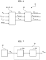
- Figure 3 exemplifies a vehicle VEH in a driving condition.
- the vehicle VEH travels along a road R having a certain inclination ⁇ with respect to the horizontal and is subject to the following forces, all parallel to the surface of the road R: a force F E of forward propulsion due to the action of the engine of the vehicle, a braking force F CD due to the aerodynamic resistance (which is dependent on the speed of the vehicle), a braking force F R due to the rolling resistance, and the component of the weight force F G parallel to the surface of the road (which in the example of Figure 3 is a braking force, but could be a propulsive force in the case of a descending stretch of road).
- ⁇ t is the time interval between two successive sampling instants
- m is the mass of the vehicle VEH
- I C is the moment of inertia of the engine (or more in general of the roatting parts, comprising also the moments of inertia of the clutch 22, of the gearbox 24, of the differential 26, and of the wheels 28)
- k is the transmission coefficient
- F E T i ⁇ k i
- F CD A air ⁇ v est 2 i
- F G mg ⁇ sin ⁇ i + ⁇ OFF
- a air is a coefficient depending upon the density of the air, the area of the front section of the vehicle, and the coefficient of aerodynamic resistance
- g is the acceleration of gravity (g ⁇ 9.81 m/s 2 )
- ⁇ OFF is the difference between the sensed angle of longitudinal inclination and the real angle of longitudinal inclination.
- the difference ⁇ OFF may be due, for example, to the fact that the inclination sensor is mounted on the frame of the vehicle, but the frame may in turn be inclined with respect to the plane of the road, for example because the load of the vehicle is set in a non-uniform way in the loading area.
- the moment of inertia Ic may be computed as the sum of the moments of inertia of all the rotating masses (engine I e , clutch I cl , gearbox I gb , differential I diff , wheels I w ) and may hence be computed according to equation 9 below:
- I C I e + I cl + I gb + I diff ⁇ gb 2 + I w ⁇ gb ⁇ ⁇ diff 2 where ⁇ gb is the gear ratio of the gearbox 24 and ⁇ diff is the transmission ratio at the axle 26.
- the estimation module 18 implements an iterative procedure for determining the values of one or more of the parameters F R , m, and ⁇ OFF .
- the estimation module 18 may comprise a module for estimating the mass 40, a module for estimating the inclination offset 42, and a module for estimating the force of rolling resistance 44, which are arranged cascaded to one another.
- the module for estimating the mass 40 receives the data ARR[] stored in the memory 16, as well as the values of the known parameters A air and Ic.
- the module 40 moreover receives a first default value m1 of the mass m, and default values of the inclination offset ⁇ OFF and of the force of rolling resistance F R .
- the module 40 computes an estimated value of the speed of the vehicle v est using equation 11 and producing a sequence of estimated values of the speed, as indicated in Table II below.
- a default value such as -1
- the module 40 repeats processing for a second value of mass m2, keeping the default values of the parameters ⁇ OFF and F R constant, to produce a second sequence of estimated values of the speed v est,m2 [] and compute a second error parameter ERR(m2).
- processing by the module 40 can be repeated iteratively, varying the value of the mass m in a set of values that comprises M discrete ordered values (for example, ten values m1, ..., m10 equally spaced apart) and producing a corresponding set of values ERR(m1), ..., ERR(m10) of the error parameter.
- the value of mass corresponding to the lowest value of the error parameter ERR is selected as value of estimation the mass of the vehicle M EST .
- the procedure carried out by the module 40 may comprise execution of further iterative cycles that make it possible to render more precise estimation of the mass of the vehicle, performing a finer division of the range of values over which the value of the parameter mass is made to vary. For instance, once a given value of mass (for example m7) has been identified in the set of values m1, ..., m10 at the end of the first iterative cycle, the procedure comprises identifying a new range of discrete ordered values centered around said identified value.
- a given value of mass for example m7
- the new range of values may comprise the same number M of values equally spaced apart from one another of the previous range, but may have a width equal to twice the difference between two consecutive ordered values of the previous range (in the example here considered and illustrated in Figure 5 , if the value of mass m7 is selected at the end of the first cycle, the values of mass used in the second cycle may be ten values equally spaced apart from one another m71, ..., m710 comprised between m6 and m8).
- the procedure may be repeated a number of times, iteratively recalling the module 40 and using each time a range of values of the mass more refined than the previous one in order to increase the precision of the estimate.
- the value selected at the end of execution of the last cycle is supplied at output by the module 40 as best estimate of the mass of the vehicle M EST .
- the procedure implemented by the estimation module 18 recalls execution of the module for estimating the inclination offset 42.
- the module for estimating the inclination offset 42 receives the data ARR[] stored in the memory 16, as well as the values of the known parameters A air and I C .
- the module 42 moreover receives a first default value ⁇ OFF 1 of the inclination offset ⁇ OFF , the previously estimated value of the mass M EST , and the default value of the force of rolling resistance F R .
- the module 42 computes an estimated value of the speed of the vehicle v est using equation 11 and producing a sequence of estimated values of the speed, as indicated in Table III below.
- a default value such as -1
- the module 42 repeats processing for a second offset value ⁇ OFF 2, keeping the values of the parameters M EST and F R constant, to produce a second sequence of estimated values of the speed v est, ⁇ OFF2 [] and compute a second error parameter ERR( ⁇ OFF 2).
- processing by the module 42 can be repeated iteratively, varying the value of the offset ⁇ OFF in a set of values that comprises M discrete ordered values and producing a corresponding set of values of the error parameter.
- the offset value corresponding to the lowest value of the error parameter ERR is selected as estimation value ⁇ OFF_EST of the offset between the sensed inclination and the real inclination of the vehicle.
- the method carried out by the module 42 may comprise execution of further iterative cycles that make it possible to render more precise estimation of the inclination offset of the vehicle, performing a finer division of the range of values over which the value of the parameter offset is made to vary, in a way similar to what has already been described previously for estimation of the mass.
- the value selected at the end of execution of the last cycle is supplied at output by the module 42 as best estimate of the inclination offset of the vehicle ⁇ OFF_EST .
- the procedure implemented by the estimation module 18 recalls execution of the module for estimating the force of rolling resistance 44, which operates in a way similar to the modules 40 and 42.
- the module for estimating the force of rolling resistance 44 receives the data ARR[] stored in the memory 16, as well as the values of the known parameters A air and I C .
- the module 44 moreover receives a first default value F R 1 of the force of rolling resistance, and the previously estimated values of the mass M EST and of the inclination offset ⁇ OFF_EST .
- the module 44 computes an estimated value of the speed of the vehicle v est using equation 11, and produces a sequence of estimated values of the speed, as indicated in Table IV below.
- a default value such as -1
- the module 44 repeats processing for a second value of force F R 2, keeping the values of the parameters M EST and ⁇ OFF_EST constant, to produce a second sequence of estimated values of the speed vest,FR2[] and compute a second error parameter ERR(F R 2).
- processing by the module 44 can be repeated iteratively, varying the value of the force F R in a set of values that comprises M discrete ordered values and producing a corresponding set of values of the error parameter.
- the value of force corresponding to the lowest value of the error parameter ERR is selected as value of estimation F R_EST of the force of rolling resistance.
- the procedure carried out by the module 44 may comprise execution of further iterative cycles that make it possible to render more precise estimation of the force of rolling resistance, performing a finer division of the range of values over which the value of the parameter force is made to vary, in a way similar to what has already been described previously.
- the value selected at the end of execution of the last cycle is supplied at output by the module 44 as best estimate of the force of rolling resistance F R_EST .
- the procedure may comprise a further level of iteration, in so far as the module 40 may be recalled again after execution of a first processing cycle by the modules 40, 42 and 44.
- the values of the inclination offset ⁇ OFF and of the force of rolling resistance F R used in equation 11 will not be the default values, but will be those computed at the previous iterative step by the respective modules 42 and 44.
- a new execution of processing by the module 40 may be followed by a new execution by the module 42 and/or the module 44, with the possibility of repeating the sequence of processing by the modules 40, 42 and 44 a number of times that may even be high.
- the order in which the modules 40, 42 and 44 are recalled may be different from what has been described previously.
- the value of the parameter ⁇ OFF_EST could first be estimated using, in equation 11, the default values of the mass m and of the force of rolling resistance F R , then the value of the parameter F R_EST could be estimated using, in equation 11, the estimated value of ⁇ OFF_EST and the default value of the mass m, and finally the value of the parameter M EST could be estimated using, in equation 11, the estimated values of ⁇ OFF_EST and F R_EST .
- an iterative procedure can be implemented for estimating even just one or two of the parameters M EST , ⁇ OFF_EST , and F R_EST .
- iterative execution of just the module 40 could be recalled using, in equation 11, the default values of the inclination offset ⁇ OFF and of the force of rolling resistance F R .
- the vectors v[], T[], ⁇ [], and k[] are reset.
- Operation of the estimation module 18 described previously hence enables, for each sequence of data ARR[] sampled during a single sampling interval (for example, 5 seconds or 10 seconds), determination of a single value of mass M EST , a single offset value ⁇ OFF_EST , and/or a single value of force F R_EST .
- the method comprises repeating the estimation of mass, inclination offset and/or force a plurality of times, using data sampled during a plurality of successive sampling intervals, provided that the vehicle is in the appropriate condition of acceleration defined previously.
- the plurality of values of mass, offset, and/or force thus produced can be the object of respective averaging operations in such a way as to produce averaged values that further improve the precision of the estimation.
- the estimation module 18 may comprise an average-computing module 60, which receives sequences of the values M EST , ⁇ OFF_EST , and/or F R_EST estimated over time and, for each of said sequences, produces a respective average value M EST_AVG , ⁇ OFF_EST_AVG and/or F R_EST_AVG .
- each average value can be computed in an "incremental" way using an incremental counter j and the average value computed previously, according to equations 15, 16, and 17 below:
- F R _ EST _ AVG j F R _ EST _ AVG j ⁇ 1 ⁇ j ⁇ 1 + F R _ EST j
- the average values thus computed can be updated at each new sampling interval (to which there corresponds generation of a new estimated value M EST , ⁇ OFF_EST and/or F R_EST ) in a continuous way, for example from the moment when the vehicle is set in motion, and can consequently refer to a large number of estimates. If, on the one hand, computing the average over a large number of sampling intervals enables improvement of the precision of the estimates by reducing the weight of possible transient events, on the other hand this average could be subject to "inertia", i.e., it could evolve slowly and might not be able to identify in a timely way the variations of the parameters of mass, inclination offset, and force of rolling resistance.
- the module 60 may be configured to store (for example, in a register of a First-In, First-Out type) only the most recently estimated values M EST , ⁇ OFF_EST , and/or F R_EST (for example, the last ten or five values received) and for computing respective average "control" values that take into account only the most recent values.
- control average values are compared with the "global" average values (i.e., the ones with longer memory) and if the control average value differs from the global average value by a percentage higher than a given threshold (for example, 30%), the global average value M EST_AVG , ⁇ OFF_EST_AVG , and/or F R_EST_AVG is reset, in so far as it is likely that a variation of the respective quantity has recently occurred (for example, the mass may vary because the vehicle is loaded with goods or else unloaded, or because the tank has been filled with fuel).
- a percentage higher than a given threshold for example, 30%
- the estimation module 18 is moreover configured to determine a margin of error M EST_ERR associated to the estimate of the mass M EST , for example the standard deviation of the mass M EST_AVG .
- M EST_ERR a margin of error associated to the estimate of the mass M EST
- the standard deviation two curves are used, one depending on the counter j, and one depending on the estimated mass M EST_AVG .
- the standard deviation may be computed as product of the values of these two curves corresponding to the current value of the counter and to the current value of the estimated mass M EST_AVG .
- the value of the mass supplied at output by the estimation module 18 may moreover be corrected by multiplying it by a factor that depends on the estimated mass M EST_AVG (for example, as a function of a calibration curve, which can compensate for possible tendencies to over-estimation or under-estimation by the method described herein).
- Figure 7 is a block diagram of a further embodiment in which a plurality of values of the estimated mass M EST (corresponding to a plurality of sampling intervals) are subjected to a different procedure for computing a final (averaged) value M FINAL , averaged according to a different algorithm.
- the embodiment of Figure 7 proves advantageous when the number of iterations executed by blocks 40, 42 and 44 is limited (for example, on account of the limitedness of the processing resources on board the vehicle VEH).
- a processing module 70 is configured to receive a plurality of discrete estimated values M EST (for example, constrained to one of the values m1, ..., m10 as in the example of Figure 5 ).
- a first processing block 700 determines whether each estimate M EST received belongs to a given category. For instance, five categories of masses are defined: VL (low), VML (medium-to-low), VM (medium), VMH (medium-to-high) and VH (high). Each category corresponds to a range delimited by respective upper and lower limits:
- a corresponding counter is incremented.
- the processing block 700 identifies the category containing the highest number of instances (i.e., the category to which the highest counter is associated) and within this category identifies the three values of mass that recur most frequently.
- a subsequent processing block 702 determines an average value M FINAL , corresponding to the average value computed only on the three values of mass that recur most frequently, weighted as a function of the respective instances.
- a hysteresis in order to prevent frequent oscillations between two different categories of masses while running the algorithm, can be implemented in such a way that passage from the previous category to a new category is made only if the difference between the number of instances in the new category and the number of instances in the previous category is higher than a given threshold, this threshold being greater than unity.
- the method described herein can be implemented in an electronic system that comprises one or more sensors configured to sense one or more parameters indicative of the dynamic state of the vehicle, and at least one electronic control unit configured to carry out the steps of the method.
Landscapes
- Physics & Mathematics (AREA)
- General Physics & Mathematics (AREA)
- Control Of Transmission Device (AREA)
- Cash Registers Or Receiving Machines (AREA)
- Motorcycle And Bicycle Frame (AREA)
- Developing Agents For Electrophotography (AREA)
Abstract
Description
- The present invention relates to methods for estimating the mass of a moving vehicle, and to corresponding electronic systems and computer program products.
- In particular, the invention relates to a method in which the mass of the vehicle is estimated as a function of the values of one or more parameters indicative of the dynamic state of the vehicle, sensed during a sampling interval whilst the vehicle is moving and its dynamic state meets a given condition of acceleration.
- Methods of the type referred to above are known in the art, but may be far from robust and/or may produce an estimate of the mass of the vehicle that is far from precise.
- The object of one or more embodiments is to provide a method for estimating the mass of a moving vehicle that is robust in regard to the variability of the driving conditions and that produces a precise estimate of the mass of the vehicle.
- According to one or more embodiments, such an object can be achieved by means of a method having the features set forth in the claims that follow.
- One or more embodiments may refer to a corresponding electronic system, which can be mounted on board a vehicle.
- One or more embodiments may refer to a corresponding computer program product that can be loaded into the memory of at least one processing circuit (e.g., an electronic control unit or ECU of a vehicle) and comprises software code portions for carrying out the steps of the method when the product is run on the at least one processing circuit. As used herein, reference to such a computer program product is understood as being equivalent to reference to a computer-readable means containing instructions for controlling the processing system in order to co-ordinate implementation of the method according to one or more embodiments. Reference to "at least one" processing circuit is intended to highlight the possibility of one or more embodiments being implemented in modular and/or distributed form: for example, one or more embodiments may envisage interaction between a number of electronic control units of the vehicle, such as units for sensing data (using sensors) and data-processing units.
- The claims form an integral part of the technical teaching provided herein in relation to the embodiments.
- In brief, one or more embodiments refer to a method for estimating the mass of a moving vehicle, comprising the following steps:
- i) sensing at least one first parameter indicative of the dynamic state of the vehicle, said at least one first parameter comprising an acceleration of the vehicle;
- ii) determining, as a function of said at least one first parameter sensed, whether the dynamic state of the vehicle meets a given condition, wherein said determining comprises verifying that the acceleration of the vehicle is higher than a respective threshold value;
- iii) in response to the fact that the dynamic state of the vehicle meets said given condition, sampling and storing respective ordered sequences of values of a plurality of second parameters indicative of the dynamic state of the vehicle during a sampling interval, said plurality of second parameters comprising: the speed of the vehicle, the torque delivered by the engine of the vehicle, the sensed angle of longitudinal inclination of the vehicle, and the transmission ratio between the engine and the drive wheels of the vehicle;
- iv) computing, for each value in said ordered sequences of values of said plurality of second parameters, a respective value of estimated speed of the vehicle as a function of: the stored values of said plurality of second parameters, a previous value of speed of the vehicle, a presumed mass of the vehicle, a presumed difference between the sensed angle of longitudinal inclination and the real angle of longitudinal inclination, and a presumed force of rolling resistance of the vehicle, to produce an ordered sequence of values of estimated speed of the vehicle;
- v) computing an error parameter as a function of differences computed between the values of sampled speed of the vehicle and the corresponding values of estimated speed of the vehicle;
- vi) repeating steps iv) and v), varying the value of the presumed mass of the vehicle in a first interval comprising M discrete ordered values, to compute a plurality of M values of the error parameter; and
- vii) selecting, as estimated value of the mass of the vehicle, the value that produces the lowest of said M computed values of the error parameter.
- Thanks to the aforesaid characteristics, the method according to the invention is robust in regard to the variability of the driving conditions and produces a precise estimate of the mass of the vehicle.
- In a preferred embodiment, the method comprises repeating steps vi) and vii). At each repetition of step vi) the value of the presumed mass of the vehicle is varied in a second interval comprising M discrete ordered values. The second interval is centered around the value of mass selected in the previous execution of step vii), and preferably has a width equal to twice the difference between two consecutive ordered values of said first interval.
- In a preferred embodiment, the method comprises:
- viii) repeating steps iv) and v), varying the value of the presumed difference between the sensed angle and the real angle of longitudinal inclination of the vehicle in a respective first interval comprising M discrete ordered values, to compute a plurality of M values of the error parameter; and
- ix) selecting, as estimated value of the difference between the sensed angle and the real angle of longitudinal inclination of the vehicle, the value that produces the lowest of said M computed values of the error parameter.
- In a preferred embodiment, the method comprises:
- x) repeating steps iv) and v), varying the value of the presumed force of rolling resistance of the vehicle in a respective first interval comprising M discrete ordered values, to compute a plurality of M values of the error parameter; and
- xi) selecting, as estimated value of the force of rolling resistance of the vehicle, the value that produces the lowest of said M computed values of the error parameter.
- In a preferred embodiment, the method comprises iteratively repeating steps vi), vii), viii), ix), x) and xi), using at each iteration, as values of presumed mass of the vehicle, presumed difference between the sensed angle of longitudinal inclination and the real angle of longitudinal inclination, and presumed force of rolling resistance of the vehicle, the respective values computed at the previous iteration.
- In a preferred embodiment, the method comprises:
- repeating steps i) to vii) to determine a plurality of estimated values of the mass of the vehicle;
- computing a global average value of said plurality of estimated values of the mass of the vehicle; and
- selecting, as estimated value of the mass of the vehicle, said global average value.
- In a preferred embodiment, the method comprises:
- repeating steps i) to xi) to determine a plurality of estimated values of the mass of the vehicle;
- computing a global average value of said plurality of estimated values of the mass of the vehicle; and
- selecting, as estimated value of the mass of the vehicle, said global average value.
- In a preferred embodiment, the method comprises:
- computing a partial average value of a subset of said plurality of estimated values of the mass of the vehicle, said subset having a cardinality lower than said plurality of values and comprising only the most recent estimated values; and
- resetting said global average value of said plurality of estimated values of the mass of the vehicle in response to the fact that said partial average value differs from said global average value by a percentage higher than or equal to a given threshold, said threshold being preferably equal to 30%.
- In a preferred embodiment, the method comprises estimating the transmission ratio between the engine and the drive wheels of the vehicle as a function of a lowpass-filtered ratio between a sensed rotational speed of the engine and the speed of the vehicle.
- In a preferred embodiment, said error parameter is computed as a function of the sum of the squared errors between the values of sampled speed of the vehicle and the corresponding values of estimated speed of the vehicle.
- In a preferred embodiment, the method comprises:
- repeating steps i) to vii) to determine a plurality of estimated values of the mass of the vehicle, said estimated values being constrained to a set of pre-set discrete values;
- dividing said plurality of estimated values of the mass of the vehicle into a set of categories, said categories corresponding to respective ranges of values, said ranges being adjacent to one another and such as to cover altogether said set of pre-set discrete values;
- identifying, from amongst said categories, the category containing the highest number of instances;
- selecting, within said identified category, P estimated values of the mass of the vehicle that present the highest number of instances;
- computing a weighted average value of the mass of the vehicle limitedly to the instances of said P selected estimated values; and
- selecting, as estimated value of the mass of the vehicle, said weighted average value.
- In a preferred embodiment, the method comprises:
- repeating steps i) to xi) to determine a plurality of estimated values of the mass of the vehicle, said estimated values being constrained to a set of pre-set discrete values;
- dividing said plurality of estimated values of the mass of the vehicle into a set of categories, said categories corresponding to respective ranges of values, said ranges being adjacent to one another and such as to cover altogether said set of pre-set discrete values;
- identifying, from among said categories, the category containing the highest number of instances;
- selecting, within said identified category, P estimated values of the mass of the vehicle that present the highest number of instances;
- computing a weighted average value of the mass of the vehicle limitedly to the instances of said P selected estimated values; and
- selecting, as estimated value of the mass of the vehicle, said weighted average value.
- In a preferred embodiment, the at least one first parameter indicative of the dynamic state of the vehicle further comprises at least one parameter selected from among:
- the speed of the vehicle;
- a signal indicative of a gear shift in progress;
- a signal indicative of a gear engaged;
- a signal indicative of activation of a retarder device acting on the transmission of the vehicle;
- a signal indicative of activation of a retarder device acting on the engine of the vehicle;
- a signal indicative of activation of a braking system of the vehicle;
- a signal indicative of activation of an antilock braking system of the vehicle;
- a signal indicative of activation of a brake-assist system of the vehicle; and
- a signal indicative of a communication anomaly in a communication network of the vehicle.
- In a preferred embodiment, determining whether the dynamic state of the vehicle meets said given condition further comprises at least one of the following:
- verifying that the speed of the vehicle is comprised between a lower threshold value and an upper threshold value;
- verifying that there is no gear change in progress;
- verifying that a gear is engaged;
- verifying that the retarder device acting on the transmission of the vehicle is not active;
- verifying that the retarder device acting on the engine of the vehicle is not active;
- verifying that the braking system of the vehicle is not active;
- verifying that the antilock braking system of the vehicle is not active,
- verifying that the brake-assist system of the vehicle is not active; and
- verifying that there are no communication anomalies in the communication network of the vehicle.
- In a preferred embodiment, an electronic system for estimating the mass of a moving vehicle comprises at least one first sensor configured to sense at least one first parameter indicative of the dynamic state of the vehicle, at least one second sensor configured for sensing a plurality of second parameters indicative of the dynamic state of the vehicle, and an electronic control unit configured to carry out the steps of the method according to one or more embodiments.
- Various embodiments will now be described, purely by way of example, with reference to the annexed figures, wherein:
-
Figure 1 is a block diagram of an electronic system configured to estimate the mass of a moving vehicle according to one or more embodiments of the present disclosure; -
Figure 2 is a diagram exemplifying the chain of transmission of motion of a vehicle; -
Figure 3 is a diagram exemplifying a vehicle in a given driving condition; -
Figure 4 is a block diagram of a module for estimating the mass of a vehicle according to one or more embodiments of the present disclosure; -
Figure 5 is a diagram exemplifying details of implementation of one or more embodiments of the present disclosure; -
Figure 6 is a block diagram of a module for estimating the mass of a vehicle according to a preferred embodiment of the present disclosure; and -
Figure 7 is a block diagram of a module for estimating the mass of a vehicle according to another preferred embodiment of the present disclosure. - In the ensuing description one or more specific details are illustrated, aimed at enabling an in-depth understanding of examples of embodiments of this description. The embodiments may be obtained without one or more of the specific details, or with other methods, components, materials, etc. In other cases, known structures, materials, or operations are not illustrated or described in the detail in such a way that certain aspects of the embodiments will not be obscured.
- Reference to "an embodiment" or "one embodiment" in the framework of the present description is intended to indicate that a particular configuration, structure, or characteristic described in relation to the embodiment is comprised in at least one embodiment. Consequently, phrases such as "in an embodiment" or "in one embodiment" that may be present in one or more points of the present description do not necessarily refer to one and the same embodiment. Moreover, particular configurations, structures, or characteristics may be combined in any adequate way in one or more embodiments.
- In all the figures annexed hereto, unless the context indicates otherwise, parts or elements that are similar are designated by the same references/numbers and a corresponding description will not be repeated for reasons of brevity.
- The references used herein are provided merely for convenience and hence do not define the sphere of protection or the scope of the embodiments.
-
Figure 1 is a block diagram of anelectronic system 1 configured to implement a method for estimating the mass of a moving vehicle, when the transmission of the vehicle is engaged, via execution of an estimation algorithm. - The
system 1 comprises an enablingmodule 10 configured to sense one or more parameters indicative of the dynamic state of the vehicle (for example, by receiving one or more messages from a CAN - Controller Area Network - of the vehicle, where each message comprises one or more signals, i.e., the values of one or more parameters) and process the values of the sensed parameters in order to determine, as a function thereof, whether the dynamic state of the vehicle meets a given condition of acceleration. For instance, the enablingmodule 10 receives from the message ERC1 a signal ERC1_DR_ActRetPcTrq indicative of the fact that a retarder device of the transmission is activated, from the message ERC1 a signal ERC1_ER_ActRetPcTrq indicative of the fact that a retarder device of the engine is activated, from the message ETC2 a signal ETC2_TransmCurGear indicative of the gear currently engaged, from the message EBC1 a signal EBC1_EbsBrkSw indicative of the fact that an EBS (Electronic Braking System) is activated, from the message EBC2 a signal EBC2_FA_speed indicative of the travel speed of the vehicle (sensed by one or more sensors mounted on the axle shafts of one or more wheels), and from the message ETC1 a signal ETC1_TransmShiftInProc indicative of the fact that a gear change is in progress. - The enabling
module 10 is configured to process the signals received (some of which are listed above purely by way of non-limiting example) and determine whether the dynamic state of the vehicle meets the condition of acceleration necessary for proper estimation of the mass. For instance, the conditions to be met may be one or more of the following: - the vehicle must be moving in forward gear;
- the speed of the vehicle must be lower than a certain maximum threshold, for example equal to 50 km/h (optionally, by implementing a comparison with hysteresis between the sensed speed and the maximum threshold);
- the speed of the vehicle must be higher than a certain minimum threshold (optionally, by implementing a comparison with hysteresis between the sensed speed and the minimum threshold);
- the (longitudinal) acceleration of the vehicle must be higher than a certain minimum threshold (optionally, by implementing a comparison with hysteresis between the sensed acceleration and the respective minimum threshold);
- there must not be any gear change in progress (for example, the clutch must be in a closed condition, with a slipping coefficient lower than 0.05, i.e., a percentage difference between the r.p.m. upstream of the clutch and the r.p.m. downstream of the clutch of less than 5%);
- a gear must be engaged (i.e., the transmission must not be in "neutral");
- the retarder device of the transmission must not be activated;
- the retarder device of the engine must not be activated;
- the brakes of the vehicle must not be activated;
- the brake-assist systems, such as ABS (Antilock Braking System) and EBS (Electronic Braking System) must not be intervening; and
- no anomalies (for example, no timeout message on the CAN) must be detected on the communication network of the vehicle.
- In the case where the
module 10 does not receive a signal directly indicating the acceleration of the vehicle, the acceleration can be computed as a function of the speed signal EBC2_FA_speed. - If the conditions referred to above (or a subset thereof, according to the specific embodiment) are met, the enabling
module 10 asserts an enable signal EN (for example, it sets it at the high logic value) to signal that the vehicle is in a dynamic condition suitable for starting the sampling of the data necessary for estimating the mass (for example, when the acceleration of the vehicle is higher than a given threshold). The enable signal EN is received in a data-acquisition module 12. - The person skilled in the sector will understand that the term "acceleration" of the vehicle is here to be understood in absolute value in so far as also a state of deceleration of the vehicle may be suitable for starting detection of the data necessary for estimating the mass. Consequently, the enabling
module 10 may be configured for verifying whether the absolute value of the (longitudinal) acceleration av of the vehicle is higher than the respective minimum threshold aV,TH : |aV | > aV,TH . - The data-
acquisition module 12 is configured to sample and store the ordered sequences of values of a plurality of parameters of the vehicle, during a sampling interval, in response to the fact that the signal EN is asserted. The duration of the sampling interval may be fixed or else configurable, and may for example be in the region of some seconds, such as 2 seconds, 5 seconds, or 10 seconds. The plurality of parameters sensed by the data-acquisition module 12 comprises the speed of the vehicle, the (net) torque delivered by the engine of the vehicle, the angle of longitudinal inclination of the vehicle with respect to the horizontal, and the coefficient k, i.e., the transmission ratio between the crankshaft and the drive wheels. In particular, the (net) torque delivered by the engine of the vehicle may be computed by themodule 12 as the torque indicated by the engine decreased by the losses due to the parasitic effects of the engine and to frictional factors of the engine. - For instance, as illustrated in
Figure 1 , the data-acquisition module 12 receives (for example from the CAN) from the message EEC1 a signal EEC1_EngSpeed indicative of the rotational speed of the crankshaft, from the message EC1 a signal EC1_EngRefTrq indicative of a reference engine torque (expressed in Nm) for all the positive torques expressed as percentages, from the message EBC2 a signal EBC2_FA_speed indicative of the travel speed of the vehicle, from the message EEC2 a signal EEC2_ActEngPcTrq indicative of an engine torque (expressed as a percentage with respect to the reference torque EC1_EngRefTrq), from the message EEC3 a signal EEC3_NomFrictPcTrq indicative of a nominal negative torque (expressed as a percentage with respect to the reference torque EC1_EngRefTrq) due to friction and/or other loads internal to the engine, from the message EEC3 a signal EEC3_ExtengParLossPcTrq indicative of a nominal negative torque (expressed as a percentage with respect to the reference torque EC1_EngRefTrq) due to parasitic effects such as auxiliary vehicle loads external to the engine, and from the message SSI a signal SSI_03_PitchAngle indicative of the angle of longitudinal inclination of the vehicle with respect to the horizontal. In addition, the data-acquisition module 12 receives from a module for computing the transmission ratio 14 a signal K indicative of the coefficient k. - With reference to
Figure 2 , the chain of transmission of motion of a vehicle may be represented schematically by anengine 20 having an output shaft coupled to the first disk of a clutch 22. The second disk of the clutch 22 is coupled to the input shaft of agearbox 24. The output shaft of thegearbox 24 is connected to adifferential device 26 arranged in the axle of the drive wheels. Two output shafts of the differential device 26 (i.e., the axle shafts) are connected to therespective drive wheels 28. The transmission ratio of thegearbox 24 is designated by gr, the transmission ratio of the differential 26 is designated by ar, and the radius of thedrive wheels 28 is designated by r. By definition, the coefficient k can hence be computed according toequation 1 below:
- In one or more embodiments, however, the coefficient k may be computed by the
module 14 as a function of the rotational speed of theengine 20 and the travel speed of the vehicle, according to equation 2 below:

Figure 1 , the module for computing thetransmission ratio 14 receives (for example, from the CAN) the signals ETC2_TransmCurGear, ETC1_TransmShiftInProc, EEC1_EngSpeed already described previously, as well as from the message TCO1 a signal TCO1_TcoOutSpeed indicative of the rotational speed of the output shaft of the gearbox and a signal TCO1_TcoVehSpeed indicative of the speed of the vehicle sensed by the tachograph, and processes these signals to determine the value of the coefficient k. - Consequently, during a sampling period, the data-
acquisition module 12 can store in a memory area 16 (for example, a buffer) a vector v[] comprising the sensed samples of the speed of the vehicle, a vector T[] comprising the sensed samples of the (net) torque delivered by the engine, a vector a[] comprising the sensed samples of the angle of longitudinal inclination of the vehicle, and a vector k[] comprising the computed samples of the coefficient k. - If, instead, the enable signal EN is not asserted (i.e., if the dynamic state of the vehicle does not meet the condition of acceleration discussed previously), the vectors v[], T[], a[] and k[] are not filled (i.e., the data are not sampled and are not stored in the memory area 16). The first value of the vector k[] can be set at a default value (for example, -1) to indicate to the
estimation module 18 that it must set the value of the estimated speed at the sensed (or real) value of speed. If the enable signal EN is de-asserted before thememory buffer 16 is completely filled with sampled data, sampling of the data can be resumed to fill thememory buffer 16 when the signal EN is asserted again. Consequently, the vectors v[], T[], α[], and k[] stored in thememory buffer 16 may comprise values corresponding to a plurality of separate time segments. The value of the vector k[] stored at each start of a new sampling time segment can be set at the default value (for example, -1) to indicate to theestimation module 18 that it must set the corresponding values of the estimated speeds at the sensed (or real) value of speed at that instant. - At the end of the sampling period, each of the vectors v[], T[], α[], and k[] hence contains one and the same number N of corresponding samples, which may be in the region of some hundreds (for example, 100, 200, or 500), as exemplified in Table I below, where v(i), T(i), α(i), and k(i) denote the values stored in the respective vectors v[], T[], α[], and k[] at the generic instant t = i:
Table I t = 1 t = 2 t = 3 ... t = N v[] v(1) v(2) v(3) ... v(N) T[] T(1) T(2) T(3) ... T(N) α[] α(1) α(2) α(3) ... α(N) k[] k(1) k(2) k(3) ... k(N) - At the end of the sampling period (when the
buffer 16 is completely filled), the data-acquisition module 12 asserts a signal TRG, which is received by anestimation module 18. In response to the fact that the signal TRG is asserted, the estimation module reads the data stored in thememory area 16, represented as a whole inFigure 1 as an array ARR[] (i.e., the set of the vectors v[], T[], α[], and k[]), and processes them according to the method described in what follows in order to estimate: - a value of the mass of the vehicle MEST;
- a value of difference between the sensed angle of longitudinal inclination and the real angle of longitudinal inclination, αOFF_EST; and
- a value of the force of rolling resistance FR_EST.
- In order to understand operation of the
estimation module 18, reference may first be made toFigure 3 , which exemplifies a vehicle VEH in a driving condition. The vehicle VEH travels along a road R having a certain inclination α with respect to the horizontal and is subject to the following forces, all parallel to the surface of the road R: a force FE of forward propulsion due to the action of the engine of the vehicle, a braking force FCD due to the aerodynamic resistance (which is dependent on the speed of the vehicle), a braking force FR due to the rolling resistance, and the component of the weight force FG parallel to the surface of the road (which in the example ofFigure 3 is a braking force, but could be a propulsive force in the case of a descending stretch of road). If the (estimated or real) speed v(i) of the vehicle is known at a given instant t = i, the speed vest(i + 1) of the vehicle at a subsequent instant t = i+1 can hence be estimated according to the equation 4 below:
gearbox 24, of the differential 26, and of the wheels 28), and k is the transmission coefficient referred to previously. - The values of the forces FE, FCD and FG can be computed according to equations 5, 6, and 7 below:


- As has been anticipated, in one or more embodiments the net torque T(i) may be computed as the torque indicated by the engine (Tindicated) decreased by the losses due to the parasitic effects of the engine (Tparasitic) and to frictional factors of the engine (Tfriction), according to equation 8 below:

- In one or more embodiments, the moment of inertia Ic may be computed as the sum of the moments of inertia of all the rotating masses (engine Ie, clutch Icl, gearbox Igb, differential Idiff, wheels Iw) and may hence be computed according to equation 9 below:

gearbox 24 and τdiff is the transmission ratio at theaxle 26. - In one or more embodiments, the coefficient Aair can be computed according to
equation 10 below:
- Consequently, equation 4 can be re-written as follows (equation 11):

- As may be noted from equation 11, the speed of the vehicle at an instant t = i+1 can then be estimated as a function of the values of the parameters v(i), T(i), k(i), and α(i) stored in the array ARR[], as a function of some known quantities (i.e., the coefficient Aair and the moment of inertia Ic proper to the vehicle VEH) and as a function of three further unknown parameters FR, m, and αOFF. The
estimation module 18 implements an iterative procedure for determining the values of one or more of the parameters FR, m, and αOFF. - In particular, as illustrated in
Figure 4 , theestimation module 18 may comprise a module for estimating themass 40, a module for estimating the inclination offset 42, and a module for estimating the force of rollingresistance 44, which are arranged cascaded to one another. - At the first iteration, the module for estimating the
mass 40 receives the data ARR[] stored in thememory 16, as well as the values of the known parameters Aair and Ic. Themodule 40 moreover receives a first default value m1 of the mass m, and default values of the inclination offset αOFF and of the force of rolling resistance FR. For each sampling instant (subsequent to the first), themodule 40 computes an estimated value of the speed of the vehicle vest using equation 11 and producing a sequence of estimated values of the speed, as indicated in Table II below.Table II t = 1 t = 2 t = 3 ... t = N vest,m1[] vest,m1(1) = v(1) vest,m1(2) vest,m1(3) ... vest,m1(N) - As indicated in Table II, the first estimated value of the speed vest,m1 (1) is set equal to the sampled value v(1) at instant t = 1, when the enable signal EN was asserted (i.e., it passed from 0 to 1). Likewise, in the case where the
buffer 16 comprises data sensed during a number of separate time segments (i.e., if the signal EN has been de-asserted and re-asserted at least once during the data-sampling step), the j-th estimated value of the speed vest,m1(j) is set equal to the sampled value v(j) at instant t = j when the enable signal EN was once again asserted; this in so far as equation 11 enables estimation of each value of speed as a function of a previous value of speed. As has been anticipated, this operation can be obtained by storing a default value (such as -1) in each element k(j) of the vector k[] that corresponds to the start of a new sampling time segment, and by storing the values of sampled speeds v(j) at the instants t = j in the respective elements vest,m1(j) of the vector vest,m1[] whenever the default value (-1) is detected in the vector k[]. - Once the values of estimated speed are computed for each sampling instant as a function of the value of mass m1, the
module 40 computes an error parameter ERR(m1) defined as the sum of the squared errors between the values of estimated speed vest and the corresponding values of sensed speed v, according toequation 12 below:
- Once the error parameters ERR(m1) are computed, the
module 40 repeats processing for a second value of mass m2, keeping the default values of the parameters αOFF and FR constant, to produce a second sequence of estimated values of the speed vest,m2[] and compute a second error parameter ERR(m2). As shown inFigure 5 , processing by themodule 40 can be repeated iteratively, varying the value of the mass m in a set of values that comprises M discrete ordered values (for example, ten values m1, ..., m10 equally spaced apart) and producing a corresponding set of values ERR(m1), ..., ERR(m10) of the error parameter. At the end of the iterative cycle carried out by themodule 40, the value of mass corresponding to the lowest value of the error parameter ERR is selected as value of estimation the mass of the vehicle MEST. - In one or more preferred embodiments, the procedure carried out by the
module 40 may comprise execution of further iterative cycles that make it possible to render more precise estimation of the mass of the vehicle, performing a finer division of the range of values over which the value of the parameter mass is made to vary. For instance, once a given value of mass (for example m7) has been identified in the set of values m1, ..., m10 at the end of the first iterative cycle, the procedure comprises identifying a new range of discrete ordered values centered around said identified value. For instance, the new range of values may comprise the same number M of values equally spaced apart from one another of the previous range, but may have a width equal to twice the difference between two consecutive ordered values of the previous range (in the example here considered and illustrated inFigure 5 , if the value of mass m7 is selected at the end of the first cycle, the values of mass used in the second cycle may be ten values equally spaced apart from one another m71, ..., m710 comprised between m6 and m8). The procedure may be repeated a number of times, iteratively recalling themodule 40 and using each time a range of values of the mass more refined than the previous one in order to increase the precision of the estimate. The value selected at the end of execution of the last cycle is supplied at output by themodule 40 as best estimate of the mass of the vehicle MEST. - Once an estimated value of mass MEST has been determined, the procedure implemented by the
estimation module 18 recalls execution of the module for estimating the inclination offset 42. At the first iteration, the module for estimating the inclination offset 42 receives the data ARR[] stored in thememory 16, as well as the values of the known parameters Aair and IC. Themodule 42 moreover receives a firstdefault value α OFF1 of the inclination offset αOFF, the previously estimated value of the mass MEST, and the default value of the force of rolling resistance FR. In a way similar to themodule 40, for each sampling instant (subsequent to the first) themodule 42 computes an estimated value of the speed of the vehicle vest using equation 11 and producing a sequence of estimated values of the speed, as indicated in Table III below.Table III t = 1 t = 2 .. t = N vest,αOFF1[] vest,αOFF1(1) = v(1) vest,αOFF1(2) .. vest,αOFF1(N) - Also in this case, the first estimated value of the speed vest,αOFF1(1) is set equal to the sampled value v(1) at instant t = 1, when the enable signal EN was asserted (i.e., it passed from 0 to 1). Likewise, in the case where the
buffer 16 comprises data sensed during a number of separate time segments, the j-th estimated value of the speed vest,αOFF1(j) is set equal to the sampled value v(j) at instant t = j when the enable signal EN was once again asserted. As has been anticipated, this operation can be obtained by storing a default value (such as -1) in each element k(j) of the vector k[] that corresponds to the start of a new sampling time segment and by storing the values of sampled speeds v(j) at instants t = j in the respective elements vest,m1(j) of the vector vest,m1[] whenever the default value (-1) is detected in the vector k[]. - Once the values of estimated speed have been computed for each sampling instant as a function of the offset
value α OFF1, themodule 42 computes an error parameter ERR(αOFF1) defined as the sum of the squared errors between the values of estimated speed vest and the values of sensed speed v, according to equation 13 below:
- Once the error parameter ERR(αOFF1) has been computed, the
module 42 repeats processing for a second offset value αOFF2, keeping the values of the parameters MEST and FR constant, to produce a second sequence of estimated values of the speed vest,αOFF2[] and compute a second error parameter ERR(αOFF2). In a way similar to what has been described with reference to the processing executed by themodule 40, processing by themodule 42 can be repeated iteratively, varying the value of the offset αOFF in a set of values that comprises M discrete ordered values and producing a corresponding set of values of the error parameter. At the end of the iterative cycle carried out by themodule 42, the offset value corresponding to the lowest value of the error parameter ERR is selected as estimation value αOFF_EST of the offset between the sensed inclination and the real inclination of the vehicle. - In one or more preferred embodiments, the method carried out by the
module 42 may comprise execution of further iterative cycles that make it possible to render more precise estimation of the inclination offset of the vehicle, performing a finer division of the range of values over which the value of the parameter offset is made to vary, in a way similar to what has already been described previously for estimation of the mass. The value selected at the end of execution of the last cycle is supplied at output by themodule 42 as best estimate of the inclination offset of the vehicle αOFF_EST. - Once an estimated value of the inclination offset αOFF_EST has been determined, the procedure implemented by the
estimation module 18 recalls execution of the module for estimating the force of rollingresistance 44, which operates in a way similar to themodules resistance 44 receives the data ARR[] stored in thememory 16, as well as the values of the known parameters Aair and IC. Themodule 44 moreover receives a firstdefault value F R1 of the force of rolling resistance, and the previously estimated values of the mass MEST and of the inclination offset αOFF_EST. In a way similar to themodules module 44 computes an estimated value of the speed of the vehicle vest using equation 11, and produces a sequence of estimated values of the speed, as indicated in Table IV below.Table IV t = 1 t = 2 .. t = N vest,FR1[] vest,FR1(1) = v(1) vest,FR1(2) .. vest,FR1(N) - Also in this case, the first estimated value of the speed vest,FR1(1) is set equal to the sampled value v(1) at instant t = 1, when the enable signal EN was asserted (i.e., it passed from 0 to 1). Likewise, in the case where the
buffer 16 comprises data sensed during a number of separate time segments, the j-th estimated value of the speed vest,FR1(j) is set equal to the sampled value v(j) at instant t = j when the enable signal EN was once again asserted. As has been anticipated, this operation can be obtained by storing a default value (such as -1) in each element k(j) of the vector k[] that corresponds to the start of a new sampling time segment, and by storing the values of sampled speeds v(j) at instants t = j in the respective elements vest,m1(j) of the vector vest,m1[] whenever the default value (-1) is detected in the vector k[]. - Once the values of estimated speed have been computed for each sampling instant as a function of the value of
force F R1, themodule 44 computes an error parameter ERR(FR1) defined as the sum of the squared errors between the values of estimated speed vest and the values of sensed speed v, according toequation 14 below:
- Once the error parameter ERR(FR1) has been computed, the
module 44 repeats processing for a second value of force FR2, keeping the values of the parameters MEST and αOFF_EST constant, to produce a second sequence of estimated values of the speed vest,FR2[] and compute a second error parameter ERR(FR2). In a way similar to what has been described with reference to the processing executed by themodules module 44 can be repeated iteratively, varying the value of the force FR in a set of values that comprises M discrete ordered values and producing a corresponding set of values of the error parameter. At the end of the iterative cycle carried out by themodule 44, the value of force corresponding to the lowest value of the error parameter ERR is selected as value of estimation FR_EST of the force of rolling resistance. - In one or more preferred embodiments, the procedure carried out by the
module 44 may comprise execution of further iterative cycles that make it possible to render more precise estimation of the force of rolling resistance, performing a finer division of the range of values over which the value of the parameter force is made to vary, in a way similar to what has already been described previously. The value selected at the end of execution of the last cycle is supplied at output by themodule 44 as best estimate of the force of rolling resistance FR_EST. - In one or more preferred embodiments, the procedure may comprise a further level of iteration, in so far as the
module 40 may be recalled again after execution of a first processing cycle by themodules respective modules module 40 may be followed by a new execution by themodule 42 and/or themodule 44, with the possibility of repeating the sequence of processing by themodules - It will moreover be noted that in one or more embodiments the order in which the
modules - It will moreover be noted that in one or more embodiments an iterative procedure can be implemented for estimating even just one or two of the parameters MEST, αOFF_EST, and FR_EST. For instance, iterative execution of just the
module 40 could be recalled using, in equation 11, the default values of the inclination offset αOFF and of the force of rolling resistance FR. - In one or more embodiments, once processing of the data stored in the
memory area 16 by theestimation module 18 is terminated, the vectors v[], T[], α[], and k[] (i.e., the memory area 16) are reset. - Operation of the
estimation module 18 described previously hence enables, for each sequence of data ARR[] sampled during a single sampling interval (for example, 5 seconds or 10 seconds), determination of a single value of mass MEST, a single offset value αOFF_EST, and/or a single value of force FR_EST. - In order to improve further the precision of the above estimates, in a preferred embodiment the method comprises repeating the estimation of mass, inclination offset and/or force a plurality of times, using data sampled during a plurality of successive sampling intervals, provided that the vehicle is in the appropriate condition of acceleration defined previously. The plurality of values of mass, offset, and/or force thus produced can be the object of respective averaging operations in such a way as to produce averaged values that further improve the precision of the estimation. In particular, as illustrated in
Figure 6 , theestimation module 18 may comprise an average-computing module 60, which receives sequences of the values MEST, αOFF_EST, and/or FR_EST estimated over time and, for each of said sequences, produces a respective average value MEST_AVG, αOFF_EST_AVG and/or FR_EST_AVG. In order not to uselessly store the entire sequences of values received in themodule 60 from themodules equations 15, 16, and 17 below:


- The average values thus computed can be updated at each new sampling interval (to which there corresponds generation of a new estimated value MEST, αOFF_EST and/or FR_EST) in a continuous way, for example from the moment when the vehicle is set in motion, and can consequently refer to a large number of estimates. If, on the one hand, computing the average over a large number of sampling intervals enables improvement of the precision of the estimates by reducing the weight of possible transient events, on the other hand this average could be subject to "inertia", i.e., it could evolve slowly and might not be able to identify in a timely way the variations of the parameters of mass, inclination offset, and force of rolling resistance.
- Consequently, in a preferred embodiment, the
module 60 may be configured to store (for example, in a register of a First-In, First-Out type) only the most recently estimated values MEST, αOFF_EST, and/or FR_EST (for example, the last ten or five values received) and for computing respective average "control" values that take into account only the most recent values. The control average values are compared with the "global" average values (i.e., the ones with longer memory) and if the control average value differs from the global average value by a percentage higher than a given threshold (for example, 30%), the global average value MEST_AVG, αOFF_EST_AVG, and/or FR_EST_AVG is reset, in so far as it is likely that a variation of the respective quantity has recently occurred (for example, the mass may vary because the vehicle is loaded with goods or else unloaded, or because the tank has been filled with fuel). - In a preferred embodiment, the
estimation module 18 is moreover configured to determine a margin of error MEST_ERR associated to the estimate of the mass MEST, for example the standard deviation of the mass MEST_AVG. To determine the standard deviation two curves are used, one depending on the counter j, and one depending on the estimated mass MEST_AVG. The standard deviation may be computed as product of the values of these two curves corresponding to the current value of the counter and to the current value of the estimated mass MEST_AVG. The value of the mass supplied at output by theestimation module 18 may moreover be corrected by multiplying it by a factor that depends on the estimated mass MEST_AVG (for example, as a function of a calibration curve, which can compensate for possible tendencies to over-estimation or under-estimation by the method described herein). -
Figure 7 is a block diagram of a further embodiment in which a plurality of values of the estimated mass MEST (corresponding to a plurality of sampling intervals) are subjected to a different procedure for computing a final (averaged) value MFINAL, averaged according to a different algorithm. In particular, the embodiment ofFigure 7 proves advantageous when the number of iterations executed byblocks - As shown in
Figure 7 , aprocessing module 70 is configured to receive a plurality of discrete estimated values MEST (for example, constrained to one of the values m1, ..., m10 as in the example ofFigure 5 ). Afirst processing block 700 determines whether each estimate MEST received belongs to a given category. For instance, five categories of masses are defined: VL (low), VML (medium-to-low), VM (medium), VMH (medium-to-high) and VH (high). Each category corresponds to a range delimited by respective upper and lower limits: - VL = [VL_1, VL_2];
- VML = [VML_1, VML_2] (possibly VML_1 = VL_2);
- VM = [VM_1, VM_2] (possibly VM_1 = VML_2);
- VMH = [VMH_1, VMH_2] (possibly VMH_1 = VM_2); and
- VH = [VH_1, VH_2] (possibly VH_1 = VMH_2).
- When an estimate MEST received by
block 40 is assigned to a given category, a corresponding counter is incremented. When the number of received estimates MEST exceeds a threshold value, theprocessing block 700 identifies the category containing the highest number of instances (i.e., the category to which the highest counter is associated) and within this category identifies the three values of mass that recur most frequently. Asubsequent processing block 702 then determines an average value MFINAL, corresponding to the average value computed only on the three values of mass that recur most frequently, weighted as a function of the respective instances. In a preferred embodiment, in order to prevent frequent oscillations between two different categories of masses while running the algorithm, a hysteresis can be implemented in such a way that passage from the previous category to a new category is made only if the difference between the number of instances in the new category and the number of instances in the previous category is higher than a given threshold, this threshold being greater than unity. - Obviously, the method described with reference to
Figure 7 for computing a final value MFINAL of the mass may be equally applied to estimation of the inclination offset αOFF and/or to estimation of the force of rolling resistance FR. - The method described herein can be implemented in an electronic system that comprises one or more sensors configured to sense one or more parameters indicative of the dynamic state of the vehicle, and at least one electronic control unit configured to carry out the steps of the method.
- Without prejudice to the underlying principles, the details and the embodiments may vary even considerably with respect to what has been described herein purely by way of example, without departing from the sphere of protection, as this is defined in the annexed claims.
Claims (15)
- A method of estimating the mass of a moving vehicle (VEH), comprising:i) sensing (10) at least one first parameter (ERC1_DR_ActRetPcTrq, ERC1_ER_ActRetPcTrq, ETC2_TransmCurGear, EBC1_EbsBrkSw, EBC2_FA_speed, ETC1_TransmShiftInProc) indicative of the dynamic state of the vehicle (VEH), said at least one first parameter comprising an acceleration of the vehicle;ii) determining (10), as a function of said at least one first parameter sensed, whether the dynamic state of the vehicle meets a given condition, wherein said determining (10) comprises verifying that the acceleration of the vehicle is higher than a respective threshold value;iii) in response to the fact that the dynamic state of the vehicle meets said given condition, sampling (12) and storing (16) respective ordered sequences of values of a plurality of second parameters (v[], T[], α[], k[]) indicative of the dynamic state of the vehicle during a sampling interval, said plurality of second parameters comprising: the speed of the vehicle (v[]), the torque delivered by the engine of the vehicle (T[]), the sensed angle of longitudinal inclination of the vehicle (α[]), and the transmission ratio between the engine and the drive wheels of the vehicle (k[]);iv) computing (18), for each value in said ordered sequences of values of said plurality of second parameters, a respective value of estimated speed of the vehicle as a function of: the stored values of said plurality of second parameters, a previous value of speed of the vehicle, a presumed mass of the vehicle, a presumed difference between the sensed angle of longitudinal inclination and the real angle of longitudinal inclination, and a presumed force of rolling resistance of the vehicle, to produce an ordered sequence of values of estimated speed of the vehicle;v) computing (18) an error parameter as a function of differences computed between the values of sampled speed of the vehicle and the corresponding values of estimated speed of the vehicle;vi) repeating (18, 40) steps iv) and v), varying the value of the presumed mass of the vehicle in a first interval (m1, ..., m10) comprising M discrete ordered values, to compute a plurality of M values of the error parameter; andvii) selecting (18, 40), as estimated value of the mass of the vehicle (MEST), the value that produces the lowest of said M computed values of the error parameter.
- The method of claim 1, comprising repeating (18, 40) steps vi) and vii), wherein at each repetition of step vi) the value of the presumed mass of the vehicle is varied in a second interval (m71, ..., m710) comprising M discrete ordered values, said second interval being centered around the value of mass (m7) selected at the previous execution of step vii), said second interval preferably having a width equal to twice the difference between two consecutive ordered values of said first interval.
- The method of any of the preceding claims, comprising:viii) repeating (18, 42) steps iv) and v), varying the value of the presumed difference between the sensed angle and the real angle of longitudinal inclination of the vehicle in a respective first interval comprising M discrete ordered values, to compute a plurality of M further values of the error parameter; andix) selecting (18, 42), as estimated value of the difference between the sensed angle and the real angle of longitudinal inclination of the vehicle (αOFF_EST), the value that produces the lowest of said M further computed values of the error parameter.
- The method of any of the preceding claims, comprising:x) repeating (18, 44) steps iv) and v), varying the value of the presumed force of rolling resistance of the vehicle in a respective first interval comprising M discrete ordered values, to compute a plurality of M further values of the error parameter; andxi) selecting (18, 44), as estimated value of the force of rolling resistance of the vehicle (FR_EST), the value that produces the lowest of said M further computed values of the error parameter.
- The method of claims 3 and 4, comprising iteratively repeating (18, 40, 42, 44) steps vi), vii), viii), ix), x) and xi), using at each iteration, as values of presumed mass of the vehicle, presumed difference between the sensed angle of longitudinal inclination and the real angle of longitudinal inclination of the vehicle, and presumed force of rolling resistance of the vehicle, the respective values computed at the previous iteration (MEST, αOFF_EST, FR_EST).
- The method of any of the preceding claims, comprising:- repeating (10, 12, 16, 18) steps i) to vii) to determine a plurality of estimated values of the mass of the vehicle (MEST);- computing (60) a global average value (MEST_AVG) of said plurality of estimated values of the mass of the vehicle; and- selecting (60), as estimated value of the mass of the vehicle, said global average value (MEST_AVG).
- The method of claims 3 and 4, comprising:- repeating (10, 12, 16, 18) steps i) to xi) to determine a plurality of estimated values of the mass of the vehicle (MEST);- computing (60) a global average value (MEST_AVG) of said plurality of estimated values of the mass of the vehicle; and- selecting (60), as estimated value of the mass of the vehicle, said global average value (MEST_AVG).
- The method of claim 6 or claim 7, comprising:- computing (60) a control average value of a subset of said plurality of estimated values of the mass of the vehicle (MEST), said subset having a cardinality lower than said plurality of estimated values of the mass of the vehicle (MEST) and comprising only the most recent estimated values; and- resetting (60) said global average value (MEST_AVG) of said plurality of estimated values of the mass of the vehicle (MEST) in response to the fact that said control average value differs from said global average value (MEST_AVG) by a percentage higher than or equal to a given threshold, said threshold being preferably equal to 30%.
- The method of any of the preceding claims, comprising estimating the transmission ratio between the engine and the drive wheels of the vehicle (k[]) as a function of a lowpass-filtered ratio between a sensed rotational speed of the engine and the speed of the vehicle.
- The method of any of the preceding claims, wherein said error parameter is computed as a function of the sum of the squared errors between the values of sampled speed of the vehicle and the corresponding values of estimated speed of the vehicle.
- The method of any of the preceding claims, comprising:- repeating (10, 12, 16, 18) steps i) to vii) to determine a plurality of estimated values of the mass of the vehicle (MEST), said estimated values being constrained to a set of pre-set discrete values;- dividing (700) said plurality of estimated values of the mass of the vehicle into a set of categories, said categories corresponding to respective ranges of values, said ranges being adjacent to one another and such as to cover altogether said set of pre-set discrete values;- identifying (700), from amongst said categories, the category containing the highest number of instances;- selecting (700), within said identified category, P estimated values of the mass of the vehicle that present the highest number of instances;- computing (702) a weighted average value of the mass of the vehicle limitedly to the instances of said P selected estimated values; and- selecting (702), as estimated value of the mass of the vehicle (MFINAL), said weighted average value.
- The method of claims 1, 3 and 4, comprising:- repeating (10, 12, 16, 18) steps i) to xi) to determine a plurality of estimated values of the mass of the vehicle (MEST), said estimated values being constrained to a set of pre-set discrete values;- dividing (700) said plurality of estimated values of the mass of the vehicle into a set of categories, said categories corresponding to respective ranges of values, said ranges being adjacent to one another and such as to cover altogether said set of pre-set discrete values;- identifying (700), from amongst said categories, the category containing the highest number of instances;- selecting (700), within said identified category, P estimated values of the mass of the vehicle that present the highest number of instances;- computing (702) a weighted average value of the mass of the vehicle limitedly to the instances of said P selected estimated values; and- selecting (702), as estimated value of the mass of the vehicle (MFINAL), said weighted average value.
- The method of any of the preceding claims, wherein said at least one first parameter indicative of the dynamic state of the vehicle further comprises at least one parameter selected from among:- the speed of the vehicle (EBC2_FA_speed);- a signal indicative of a gear shift in progress (ETC1_TransmShiftInProc);- a signal indicative of a gear engaged (ETC2_TransmCurGear);- a signal indicative of activation of a retarder device acting on the transmission of the vehicle (ERC1_DR_ActRetPcTrq);- a signal indicative of activation of a retarder device acting on the engine of the vehicle (ERC1_ER_ActRetPcTrq);- a signal indicative of activation of a braking system of the vehicle (EBC1_EbsBrkSw);- a signal indicative of activation of an antilock braking system of the vehicle;- a signal indicative of activation of a brake-assist system of the vehicle; and- a signal indicative of a communication anomaly in a communication network of the vehicle;and wherein determining (10) whether the dynamic state of the vehicle meets said given condition further comprises at least one of the following:- verifying that the speed of the vehicle is comprised between a lower threshold value and an upper threshold value;- verifying that there is no gear change in progress;- verifying that a gear is engaged;- verifying that the retarder device acting on the transmission of the vehicle is not active;- verifying that the retarder device acting on the engine of the vehicle is not active;- verifying that the braking system of the vehicle is not active;- verifying that the antilock braking system of the vehicle is not active;- verifying that the brake-assist system of the vehicle is not active; and- verifying that there are no communication anomalies in the communication network of the vehicle.
- An electronic system (1) for estimating the mass of a moving vehicle (VEH), comprising:- at least one first sensor configured for sensing at least one first parameter (ERC1_DR_ActRetPcTrq, ERC1_ER_ActRetPcTrq, ETC2_TransmCurGear, EBC1_EbsBrkSw, EBC2_FA_speed, ETC1_TransmShiftInProc) indicative of the dynamic state of the vehicle (VEH);- at least one second sensor configured to sense a plurality of second parameters (v[], T[], α[], k[]) indicative of the dynamic state of the vehicle (VEH); and- an electronic control unit (10, 12, 14, 16, 18) configured to carry out the steps of the method according to any of the preceding claims.
- A computer program product that can be loaded into a memory of an electronic control unit of a system according to claim 14 and comprising software code instructions for carrying out the steps of the method according to any of claims 1 to 13 as a result of said computer program product being executed on said electronic control unit.
Applications Claiming Priority (1)
| Application Number | Priority Date | Filing Date | Title |
|---|---|---|---|
| IT102021000026861A IT202100026861A1 (en) | 2021-10-19 | 2021-10-19 | "Procedure for estimating the mass of a moving vehicle, corresponding IT system and product" |
Publications (2)
| Publication Number | Publication Date |
|---|---|
| EP4170299A1 true EP4170299A1 (en) | 2023-04-26 |
| EP4170299B1 EP4170299B1 (en) | 2025-08-13 |
Family
ID=79269883
Family Applications (1)
| Application Number | Title | Priority Date | Filing Date |
|---|---|---|---|
| EP22201810.3A Active EP4170299B1 (en) | 2021-10-19 | 2022-10-17 | Method of estimating the mass of a moving vehicle, corresponding system and computer program product |
Country Status (2)
| Country | Link |
|---|---|
| EP (1) | EP4170299B1 (en) |
| IT (1) | IT202100026861A1 (en) |
Families Citing this family (1)
| Publication number | Priority date | Publication date | Assignee | Title |
|---|---|---|---|---|
| IT202300001494A1 (en) | 2023-01-31 | 2024-07-31 | Iveco Spa | "PROCEDURE FOR PERFORMING PREDICTIVE ESTIMATES OF THE SPEED OF A MOVING VEHICLE, CORRESPONDING SYSTEM AND COMPUTER PRODUCT" |
Citations (2)
| Publication number | Priority date | Publication date | Assignee | Title |
|---|---|---|---|---|
| GB2535773A (en) * | 2015-02-27 | 2016-08-31 | Jaguar Land Rover Ltd | Vehicle mass estimation |
| US20190226905A1 (en) * | 2016-06-30 | 2019-07-25 | Compagnie Generale Des Etablissements Michelin | Method and device for determining an estimate of the total mass of a motor vehicle |
-
2021
- 2021-10-19 IT IT102021000026861A patent/IT202100026861A1/en unknown
-
2022
- 2022-10-17 EP EP22201810.3A patent/EP4170299B1/en active Active
Patent Citations (2)
| Publication number | Priority date | Publication date | Assignee | Title |
|---|---|---|---|---|
| GB2535773A (en) * | 2015-02-27 | 2016-08-31 | Jaguar Land Rover Ltd | Vehicle mass estimation |
| US20190226905A1 (en) * | 2016-06-30 | 2019-07-25 | Compagnie Generale Des Etablissements Michelin | Method and device for determining an estimate of the total mass of a motor vehicle |
Also Published As
| Publication number | Publication date |
|---|---|
| EP4170299B1 (en) | 2025-08-13 |
| IT202100026861A1 (en) | 2023-04-19 |
Similar Documents
| Publication | Publication Date | Title |
|---|---|---|
| CN103661395B (en) | Dynamic road gradient is estimated | |
| CN103264669B (en) | Heavy vehicle weight real-time identification method based on CAN information and function principle | |
| CN111169481B (en) | System and method for estimating vehicle wheel speed | |
| CN103661394B (en) | Road gradient estimation arbitration | |
| US8630767B2 (en) | Estimation of the load of a vehicle | |
| CN105722735B (en) | Method for determining vehicle speed parameters | |
| EP2187223B1 (en) | System and method for compensating vehicle sensor signals | |
| CN106379197B (en) | Method and device for distributing driving torque based on predicted acceleration and automobile | |
| US6871530B2 (en) | Physical quantity estimating apparatus and tire state determining apparatus, and estimating method of same and determination method of same | |
| US9988057B2 (en) | Method and device for determining the mass of a motor vehicle, and a motor vehicle with a device of this type | |
| US20090177346A1 (en) | Dynamic estimation of vehicle inertial parameters and tire forces from tire sensors | |
| Kim et al. | Development of estimation algorithms for vehicle’s mass and road grade | |
| EP4170299B1 (en) | Method of estimating the mass of a moving vehicle, corresponding system and computer program product | |
| JP2012149925A (en) | Running resistance calculation device | |
| CN112319481B (en) | Vehicle mass estimation and gradient automatic identification method based on oil mass | |
| CN116985644A (en) | Recovery torque intervention control method, system and vehicle | |
| CN108819950A (en) | The vehicle speed estimation method and system of automobile stability control system | |
| JP3619388B2 (en) | Estimating and calculating device for height of center of gravity of vehicle | |
| US12146780B1 (en) | Real-time reporting and estimating of mass of vehicles using drive characteristics | |
| US11332150B2 (en) | System and method for controlling wheel slip of vehicle | |
| CN117842065A (en) | Vehicle mass estimation method, device, electronic device and readable storage medium | |
| CN109131341B (en) | Driving wheel slip detection method and system for all-wheel independent driving vehicle | |
| WO2012127139A1 (en) | Estimation of the rolling radius of a wheel and of the speed of a motor vehicle | |
| US6691011B1 (en) | Method of estimating vehicle deceleration during a transmission gear shift | |
| JP2002104158A (en) | Road friction state calculation device, tire type determination device, tire wear determination device, road surface inclination estimation device, and offset correction device for acceleration sensor |
Legal Events
| Date | Code | Title | Description |
|---|---|---|---|
| PUAI | Public reference made under article 153(3) epc to a published international application that has entered the european phase |
Free format text: ORIGINAL CODE: 0009012 |
|
| STAA | Information on the status of an ep patent application or granted ep patent |
Free format text: STATUS: THE APPLICATION HAS BEEN PUBLISHED |
|
| AK | Designated contracting states |
Kind code of ref document: A1 Designated state(s): AL AT BE BG CH CY CZ DE DK EE ES FI FR GB GR HR HU IE IS IT LI LT LU LV MC ME MK MT NL NO PL PT RO RS SE SI SK SM TR |
|
| STAA | Information on the status of an ep patent application or granted ep patent |
Free format text: STATUS: REQUEST FOR EXAMINATION WAS MADE |
|
| 17P | Request for examination filed |
Effective date: 20231011 |
|
| RBV | Designated contracting states (corrected) |
Designated state(s): AL AT BE BG CH CY CZ DE DK EE ES FI FR GB GR HR HU IE IS IT LI LT LU LV MC ME MK MT NL NO PL PT RO RS SE SI SK SM TR |
|
| GRAP | Despatch of communication of intention to grant a patent |
Free format text: ORIGINAL CODE: EPIDOSNIGR1 |
|
| STAA | Information on the status of an ep patent application or granted ep patent |
Free format text: STATUS: GRANT OF PATENT IS INTENDED |
|
| GRAJ | Information related to disapproval of communication of intention to grant by the applicant or resumption of examination proceedings by the epo deleted |
Free format text: ORIGINAL CODE: EPIDOSDIGR1 |
|
| STAA | Information on the status of an ep patent application or granted ep patent |
Free format text: STATUS: REQUEST FOR EXAMINATION WAS MADE |
|
| GRAP | Despatch of communication of intention to grant a patent |
Free format text: ORIGINAL CODE: EPIDOSNIGR1 |
|
| STAA | Information on the status of an ep patent application or granted ep patent |
Free format text: STATUS: GRANT OF PATENT IS INTENDED |
|
| INTG | Intention to grant announced |
Effective date: 20250319 |
|
| INTG | Intention to grant announced |
Effective date: 20250328 |
|
| GRAS | Grant fee paid |
Free format text: ORIGINAL CODE: EPIDOSNIGR3 |
|
| GRAA | (expected) grant |
Free format text: ORIGINAL CODE: 0009210 |
|
| STAA | Information on the status of an ep patent application or granted ep patent |
Free format text: STATUS: THE PATENT HAS BEEN GRANTED |
|
| P01 | Opt-out of the competence of the unified patent court (upc) registered |
Free format text: CASE NUMBER: APP_27363/2025 Effective date: 20250610 |
|
| AK | Designated contracting states |
Kind code of ref document: B1 Designated state(s): AL AT BE BG CH CY CZ DE DK EE ES FI FR GB GR HR HU IE IS IT LI LT LU LV MC ME MK MT NL NO PL PT RO RS SE SI SK SM TR |
|
| REG | Reference to a national code |
Ref country code: GB Ref legal event code: FG4D |
|
| REG | Reference to a national code |
Ref country code: CH Ref legal event code: EP |
|
| REG | Reference to a national code |
Ref country code: DE Ref legal event code: R096 Ref document number: 602022019314 Country of ref document: DE |
|
| REG | Reference to a national code |
Ref country code: IE Ref legal event code: FG4D |
|
| REG | Reference to a national code |
Ref country code: NL Ref legal event code: MP Effective date: 20250813 |
|
| PG25 | Lapsed in a contracting state [announced via postgrant information from national office to epo] |
Ref country code: IS Free format text: LAPSE BECAUSE OF FAILURE TO SUBMIT A TRANSLATION OF THE DESCRIPTION OR TO PAY THE FEE WITHIN THE PRESCRIBED TIME-LIMIT Effective date: 20251213 |
|
| PGFP | Annual fee paid to national office [announced via postgrant information from national office to epo] |
Ref country code: DE Payment date: 20251028 Year of fee payment: 4 |
|
| PG25 | Lapsed in a contracting state [announced via postgrant information from national office to epo] |
Ref country code: NO Free format text: LAPSE BECAUSE OF FAILURE TO SUBMIT A TRANSLATION OF THE DESCRIPTION OR TO PAY THE FEE WITHIN THE PRESCRIBED TIME-LIMIT Effective date: 20251113 |
|
| REG | Reference to a national code |
Ref country code: LT Ref legal event code: MG9D |
|
| PG25 | Lapsed in a contracting state [announced via postgrant information from national office to epo] |
Ref country code: PT Free format text: LAPSE BECAUSE OF FAILURE TO SUBMIT A TRANSLATION OF THE DESCRIPTION OR TO PAY THE FEE WITHIN THE PRESCRIBED TIME-LIMIT Effective date: 20251215 |
|
| PG25 | Lapsed in a contracting state [announced via postgrant information from national office to epo] |
Ref country code: FI Free format text: LAPSE BECAUSE OF FAILURE TO SUBMIT A TRANSLATION OF THE DESCRIPTION OR TO PAY THE FEE WITHIN THE PRESCRIBED TIME-LIMIT Effective date: 20250813 |
|
| PG25 | Lapsed in a contracting state [announced via postgrant information from national office to epo] |
Ref country code: HR Free format text: LAPSE BECAUSE OF FAILURE TO SUBMIT A TRANSLATION OF THE DESCRIPTION OR TO PAY THE FEE WITHIN THE PRESCRIBED TIME-LIMIT Effective date: 20250813 Ref country code: NL Free format text: LAPSE BECAUSE OF FAILURE TO SUBMIT A TRANSLATION OF THE DESCRIPTION OR TO PAY THE FEE WITHIN THE PRESCRIBED TIME-LIMIT Effective date: 20250813 |
|
| PGFP | Annual fee paid to national office [announced via postgrant information from national office to epo] |
Ref country code: FR Payment date: 20251027 Year of fee payment: 4 |
|
| PG25 | Lapsed in a contracting state [announced via postgrant information from national office to epo] |
Ref country code: GR Free format text: LAPSE BECAUSE OF FAILURE TO SUBMIT A TRANSLATION OF THE DESCRIPTION OR TO PAY THE FEE WITHIN THE PRESCRIBED TIME-LIMIT Effective date: 20251114 |
|
| PG25 | Lapsed in a contracting state [announced via postgrant information from national office to epo] |
Ref country code: SE Free format text: LAPSE BECAUSE OF FAILURE TO SUBMIT A TRANSLATION OF THE DESCRIPTION OR TO PAY THE FEE WITHIN THE PRESCRIBED TIME-LIMIT Effective date: 20250813 |
|
| PG25 | Lapsed in a contracting state [announced via postgrant information from national office to epo] |
Ref country code: LV Free format text: LAPSE BECAUSE OF FAILURE TO SUBMIT A TRANSLATION OF THE DESCRIPTION OR TO PAY THE FEE WITHIN THE PRESCRIBED TIME-LIMIT Effective date: 20250813 |
|
| PG25 | Lapsed in a contracting state [announced via postgrant information from national office to epo] |
Ref country code: BG Free format text: LAPSE BECAUSE OF FAILURE TO SUBMIT A TRANSLATION OF THE DESCRIPTION OR TO PAY THE FEE WITHIN THE PRESCRIBED TIME-LIMIT Effective date: 20250813 Ref country code: PL Free format text: LAPSE BECAUSE OF FAILURE TO SUBMIT A TRANSLATION OF THE DESCRIPTION OR TO PAY THE FEE WITHIN THE PRESCRIBED TIME-LIMIT Effective date: 20250813 |
|
| PG25 | Lapsed in a contracting state [announced via postgrant information from national office to epo] |
Ref country code: RS Free format text: LAPSE BECAUSE OF FAILURE TO SUBMIT A TRANSLATION OF THE DESCRIPTION OR TO PAY THE FEE WITHIN THE PRESCRIBED TIME-LIMIT Effective date: 20251113 |
|
| PG25 | Lapsed in a contracting state [announced via postgrant information from national office to epo] |
Ref country code: ES Free format text: LAPSE BECAUSE OF FAILURE TO SUBMIT A TRANSLATION OF THE DESCRIPTION OR TO PAY THE FEE WITHIN THE PRESCRIBED TIME-LIMIT Effective date: 20250813 |
|
| REG | Reference to a national code |
Ref country code: AT Ref legal event code: MK05 Ref document number: 1825108 Country of ref document: AT Kind code of ref document: T Effective date: 20250813 |
|
| PG25 | Lapsed in a contracting state [announced via postgrant information from national office to epo] |
Ref country code: RO Free format text: LAPSE BECAUSE OF FAILURE TO SUBMIT A TRANSLATION OF THE DESCRIPTION OR TO PAY THE FEE WITHIN THE PRESCRIBED TIME-LIMIT Effective date: 20250813 |
|
| PG25 | Lapsed in a contracting state [announced via postgrant information from national office to epo] |
Ref country code: SM Free format text: LAPSE BECAUSE OF FAILURE TO SUBMIT A TRANSLATION OF THE DESCRIPTION OR TO PAY THE FEE WITHIN THE PRESCRIBED TIME-LIMIT Effective date: 20250813 |
|
| PG25 | Lapsed in a contracting state [announced via postgrant information from national office to epo] |
Ref country code: DK Free format text: LAPSE BECAUSE OF FAILURE TO SUBMIT A TRANSLATION OF THE DESCRIPTION OR TO PAY THE FEE WITHIN THE PRESCRIBED TIME-LIMIT Effective date: 20250813 |
|
| PG25 | Lapsed in a contracting state [announced via postgrant information from national office to epo] |
Ref country code: AT Free format text: LAPSE BECAUSE OF FAILURE TO SUBMIT A TRANSLATION OF THE DESCRIPTION OR TO PAY THE FEE WITHIN THE PRESCRIBED TIME-LIMIT Effective date: 20250813 |
|
| PG25 | Lapsed in a contracting state [announced via postgrant information from national office to epo] |
Ref country code: IT Free format text: LAPSE BECAUSE OF FAILURE TO SUBMIT A TRANSLATION OF THE DESCRIPTION OR TO PAY THE FEE WITHIN THE PRESCRIBED TIME-LIMIT Effective date: 20250813 |
|
| PG25 | Lapsed in a contracting state [announced via postgrant information from national office to epo] |
Ref country code: CZ Free format text: LAPSE BECAUSE OF FAILURE TO SUBMIT A TRANSLATION OF THE DESCRIPTION OR TO PAY THE FEE WITHIN THE PRESCRIBED TIME-LIMIT Effective date: 20250813 |
|
| PG25 | Lapsed in a contracting state [announced via postgrant information from national office to epo] |
Ref country code: EE Free format text: LAPSE BECAUSE OF FAILURE TO SUBMIT A TRANSLATION OF THE DESCRIPTION OR TO PAY THE FEE WITHIN THE PRESCRIBED TIME-LIMIT Effective date: 20250813 Ref country code: SK Free format text: LAPSE BECAUSE OF FAILURE TO SUBMIT A TRANSLATION OF THE DESCRIPTION OR TO PAY THE FEE WITHIN THE PRESCRIBED TIME-LIMIT Effective date: 20250813 |