EP4170265A1 - Refrigeration cycle device - Google Patents
Refrigeration cycle device Download PDFInfo
- Publication number
- EP4170265A1 EP4170265A1 EP20940660.2A EP20940660A EP4170265A1 EP 4170265 A1 EP4170265 A1 EP 4170265A1 EP 20940660 A EP20940660 A EP 20940660A EP 4170265 A1 EP4170265 A1 EP 4170265A1
- Authority
- EP
- European Patent Office
- Prior art keywords
- expansion valve
- opening degree
- downstream
- upstream
- refrigerant
- Prior art date
- Legal status (The legal status is an assumption and is not a legal conclusion. Google has not performed a legal analysis and makes no representation as to the accuracy of the status listed.)
- Granted
Links
Images


Classifications
-
- F—MECHANICAL ENGINEERING; LIGHTING; HEATING; WEAPONS; BLASTING
- F24—HEATING; RANGES; VENTILATING
- F24F—AIR-CONDITIONING; AIR-HUMIDIFICATION; VENTILATION; USE OF AIR CURRENTS FOR SCREENING
- F24F11/00—Control or safety arrangements
- F24F11/70—Control systems characterised by their outputs; Constructional details thereof
- F24F11/80—Control systems characterised by their outputs; Constructional details thereof for controlling the temperature of the supplied air
- F24F11/83—Control systems characterised by their outputs; Constructional details thereof for controlling the temperature of the supplied air by controlling the supply of heat-exchange fluids to heat-exchangers
- F24F11/84—Control systems characterised by their outputs; Constructional details thereof for controlling the temperature of the supplied air by controlling the supply of heat-exchange fluids to heat-exchangers using valves
-
- F—MECHANICAL ENGINEERING; LIGHTING; HEATING; WEAPONS; BLASTING
- F25—REFRIGERATION OR COOLING; COMBINED HEATING AND REFRIGERATION SYSTEMS; HEAT PUMP SYSTEMS; MANUFACTURE OR STORAGE OF ICE; LIQUEFACTION SOLIDIFICATION OF GASES
- F25B—REFRIGERATION MACHINES, PLANTS OR SYSTEMS; COMBINED HEATING AND REFRIGERATION SYSTEMS; HEAT PUMP SYSTEMS
- F25B1/00—Compression machines, plants or systems with non-reversible cycle
-
- F—MECHANICAL ENGINEERING; LIGHTING; HEATING; WEAPONS; BLASTING
- F25—REFRIGERATION OR COOLING; COMBINED HEATING AND REFRIGERATION SYSTEMS; HEAT PUMP SYSTEMS; MANUFACTURE OR STORAGE OF ICE; LIQUEFACTION SOLIDIFICATION OF GASES
- F25B—REFRIGERATION MACHINES, PLANTS OR SYSTEMS; COMBINED HEATING AND REFRIGERATION SYSTEMS; HEAT PUMP SYSTEMS
- F25B41/00—Fluid-circulation arrangements
- F25B41/30—Expansion means; Dispositions thereof
- F25B41/39—Dispositions with two or more expansion means arranged in series, i.e. multi-stage expansion, on a refrigerant line leading to the same evaporator
-
- F—MECHANICAL ENGINEERING; LIGHTING; HEATING; WEAPONS; BLASTING
- F25—REFRIGERATION OR COOLING; COMBINED HEATING AND REFRIGERATION SYSTEMS; HEAT PUMP SYSTEMS; MANUFACTURE OR STORAGE OF ICE; LIQUEFACTION SOLIDIFICATION OF GASES
- F25B—REFRIGERATION MACHINES, PLANTS OR SYSTEMS; COMBINED HEATING AND REFRIGERATION SYSTEMS; HEAT PUMP SYSTEMS
- F25B49/00—Arrangement or mounting of control or safety devices
- F25B49/02—Arrangement or mounting of control or safety devices for compression type machines, plants or systems
-
- F—MECHANICAL ENGINEERING; LIGHTING; HEATING; WEAPONS; BLASTING
- F25—REFRIGERATION OR COOLING; COMBINED HEATING AND REFRIGERATION SYSTEMS; HEAT PUMP SYSTEMS; MANUFACTURE OR STORAGE OF ICE; LIQUEFACTION SOLIDIFICATION OF GASES
- F25B—REFRIGERATION MACHINES, PLANTS OR SYSTEMS; COMBINED HEATING AND REFRIGERATION SYSTEMS; HEAT PUMP SYSTEMS
- F25B2400/00—Component parts or details not otherwise provided for in this subclass
- F25B2400/16—Receivers
-
- F—MECHANICAL ENGINEERING; LIGHTING; HEATING; WEAPONS; BLASTING
- F25—REFRIGERATION OR COOLING; COMBINED HEATING AND REFRIGERATION SYSTEMS; HEAT PUMP SYSTEMS; MANUFACTURE OR STORAGE OF ICE; LIQUEFACTION SOLIDIFICATION OF GASES
- F25B—REFRIGERATION MACHINES, PLANTS OR SYSTEMS; COMBINED HEATING AND REFRIGERATION SYSTEMS; HEAT PUMP SYSTEMS
- F25B2600/00—Control issues
- F25B2600/25—Control of valves
- F25B2600/2513—Expansion valves
-
- F—MECHANICAL ENGINEERING; LIGHTING; HEATING; WEAPONS; BLASTING
- F25—REFRIGERATION OR COOLING; COMBINED HEATING AND REFRIGERATION SYSTEMS; HEAT PUMP SYSTEMS; MANUFACTURE OR STORAGE OF ICE; LIQUEFACTION SOLIDIFICATION OF GASES
- F25B—REFRIGERATION MACHINES, PLANTS OR SYSTEMS; COMBINED HEATING AND REFRIGERATION SYSTEMS; HEAT PUMP SYSTEMS
- F25B2700/00—Sensing or detecting of parameters; Sensors therefor
- F25B2700/19—Pressures
- F25B2700/193—Pressures of the compressor
- F25B2700/1931—Discharge pressures
-
- F—MECHANICAL ENGINEERING; LIGHTING; HEATING; WEAPONS; BLASTING
- F25—REFRIGERATION OR COOLING; COMBINED HEATING AND REFRIGERATION SYSTEMS; HEAT PUMP SYSTEMS; MANUFACTURE OR STORAGE OF ICE; LIQUEFACTION SOLIDIFICATION OF GASES
- F25B—REFRIGERATION MACHINES, PLANTS OR SYSTEMS; COMBINED HEATING AND REFRIGERATION SYSTEMS; HEAT PUMP SYSTEMS
- F25B2700/00—Sensing or detecting of parameters; Sensors therefor
- F25B2700/19—Pressures
- F25B2700/193—Pressures of the compressor
- F25B2700/1933—Suction pressures
-
- F—MECHANICAL ENGINEERING; LIGHTING; HEATING; WEAPONS; BLASTING
- F25—REFRIGERATION OR COOLING; COMBINED HEATING AND REFRIGERATION SYSTEMS; HEAT PUMP SYSTEMS; MANUFACTURE OR STORAGE OF ICE; LIQUEFACTION SOLIDIFICATION OF GASES
- F25B—REFRIGERATION MACHINES, PLANTS OR SYSTEMS; COMBINED HEATING AND REFRIGERATION SYSTEMS; HEAT PUMP SYSTEMS
- F25B2700/00—Sensing or detecting of parameters; Sensors therefor
- F25B2700/21—Temperatures
- F25B2700/2115—Temperatures of a compressor or the drive means therefor
- F25B2700/21152—Temperatures of a compressor or the drive means therefor at the discharge side of the compressor
-
- F—MECHANICAL ENGINEERING; LIGHTING; HEATING; WEAPONS; BLASTING
- F25—REFRIGERATION OR COOLING; COMBINED HEATING AND REFRIGERATION SYSTEMS; HEAT PUMP SYSTEMS; MANUFACTURE OR STORAGE OF ICE; LIQUEFACTION SOLIDIFICATION OF GASES
- F25B—REFRIGERATION MACHINES, PLANTS OR SYSTEMS; COMBINED HEATING AND REFRIGERATION SYSTEMS; HEAT PUMP SYSTEMS
- F25B2700/00—Sensing or detecting of parameters; Sensors therefor
- F25B2700/21—Temperatures
- F25B2700/2116—Temperatures of a condenser
- F25B2700/21163—Temperatures of a condenser of the refrigerant at the outlet of the condenser
-
- Y—GENERAL TAGGING OF NEW TECHNOLOGICAL DEVELOPMENTS; GENERAL TAGGING OF CROSS-SECTIONAL TECHNOLOGIES SPANNING OVER SEVERAL SECTIONS OF THE IPC; TECHNICAL SUBJECTS COVERED BY FORMER USPC CROSS-REFERENCE ART COLLECTIONS [XRACs] AND DIGESTS
- Y02—TECHNOLOGIES OR APPLICATIONS FOR MITIGATION OR ADAPTATION AGAINST CLIMATE CHANGE
- Y02B—CLIMATE CHANGE MITIGATION TECHNOLOGIES RELATED TO BUILDINGS, e.g. HOUSING, HOUSE APPLIANCES OR RELATED END-USER APPLICATIONS
- Y02B30/00—Energy efficient heating, ventilation or air conditioning [HVAC]
- Y02B30/70—Efficient control or regulation technologies, e.g. for control of refrigerant flow, motor or heating
Definitions
- the present invention relates to a refrigeration cycle apparatus provided with a receiver that stores liquid refrigerant.
- Some refrigeration cycle apparatuses have a refrigerant circuit which includes an upstream expansion valve, a receiver configured to store liquid refrigerant, and a downstream expansion valve, and in which the degree of subcooling is controlled by the upstream expansion valve and the degree of suction superheat is controlled by the downstream expansion valve.
- certain refrigeration cycle apparatuses include a liquid storage determination module that determines whether or not liquid refrigerant is stored in the receiver (see Patent Literature 1, for example).
- Patent Literature 1 Japanese Unexamined Patent Application Publication JP 2019- 148 395 A
- the present invention is applied to solve the above problem, and relates to a refrigeration cycle apparatus capable of reducing an unnecessary variation of the amount of liquid refrigerant in a receiver to avoid deterioration of a control performance.
- a refrigeration cycle apparatus includes a refrigerant circuit in which a compressor configured to compress refrigerant, a condenser, a receiver configured to store the refrigerant, and an evaporator are connected by pipes.
- the refrigeration cycle apparatus includes: an upstream expansion valve whose opening degree is variable and which is provided between the condenser and the receiver in the refrigerant circuit; a downstream expansion valve whose opening degree is variable and which is provided between the receiver and the evaporator in the refrigerant circuit; and a controller configured to control the opening degree of the upstream expansion valve and the opening degree of the downstream expansion valve.
- the controller is configured to: compute the opening degree of the downstream expansion valve and a provisional opening degree of the upstream expansion valve; compute a correction value for the opening degree of the upstream expansion valve based on at least a difference between the computed opening degree of the downstream expansion valve and an opening degree thereof that is being set; and perform a control to set the opening degree of the downstream expansion valve to the computed opening degree of the downstream expansion valve and to set the opening degree of the upstream expansion valve to an opening degree obtained by correcting the computed provisional opening degree of the upstream expansion valve by the correction value, in conjunction with the downstream expansion valve.
- the correction value for the opening degree of the upstream expansion valve or a correction change amount of the opening degree of the upstream expansion valve, which is a difference between the computed correction value and a previous correction value, is a value having a same sign as the difference between the opening degrees of the downstream expansion valve.
- the upstream expansion valve when the opening degree of the downstream expansion valve is changed to the computed opening degree, the upstream expansion valve is controlled to have an opening degree corrected by a correction value computed based on the difference between the opening degree between the downstream expansion valve, and the correction value or an amount of correction change has the same sign as the difference between the opening degrees of the downstream expansion valve.
- the opening degree of the downstream expansion valve is changed to the computed opening degree, the variation of the amount of the liquid refrigerant on the upstream side and the downstream side of the receiver is reduced, whereby the variation of the amount of the liquid refrigerant in the receiver is reduced.
- the amount of the refrigerant in the refrigerant circuit can be controlled using the liquid refrigerant stored in the receiver under the control of the upstream expansion valve and the downstream expansion valve, and thus deterioration of the control performance of the upstream expansion valve and the downstream expansion valve can thus be avoided.
- a refrigeration cycle apparatus 1 according to each of embodiments of the present invention will be described with reference to the drawings.
- components that are the same as or equivalent to those in a previous figure or previous figures are denoted by the same reference signs, and the same is true of the entire text of the specification.
- FIG. 1 is a schematic diagram illustrating an example of the configuration of a refrigeration cycle apparatus 1 according to Embodiment 1.
- the refrigeration cycle apparatus 1 includes a controller 2, a compressor 3, a condenser 4, an upstream expansion valve 5, a receiver 6, a downstream expansion valve 7, and an evaporator 8.
- the compressor 3, the condenser 4, the upstream expansion valve 5, the receiver 6, the downstream expansion valve 7, and the evaporator 8 are connected by pipes 9, whereby a refrigerant circuit 10 is formed.
- refrigerant circuit 10 refrigerant flows.
- Solid arrows in FIG. 1 indicate flow directions of the refrigerant. The following description is made by referring to by way of example the case where the refrigeration cycle apparatus 1 is an air-conditioning apparatus, but the refrigeration cycle apparatus 1 is not limited to the air-conditioning apparatus.
- the compressor 3 compresses and discharges sucked refrigerant.
- the compressor 3 may be, for example, a compressor whose capacity (amount of refrigerant to be fed per unit time) is changed when the driving frequency is arbitrarily changed by an inverter circuit (not illustrated).
- the condenser 4 is provided on the discharge side of the compressor 3.
- the condenser 4 causes heat exchange to be performed between the refrigerant and air, thereby condensing the refrigerant to liquefy the refrigerant and heat the air.
- the upstream expansion valve 5 is provided at the pipe 9 between the condenser 4 and the receiver 6 in the refrigerant circuit 10.
- the upstream expansion valve 5 is an expansion valve whose opening degree can be changed, such as an electronic expansion valve, and adjusts the pressure and the flow rate of the refrigerant.
- the receiver 6 is a refrigerant container that stores the refrigerant.
- the receiver 6 is provided at the pipe 9 between the condenser 4 and the evaporator 8, and stores liquid refrigerant that is left as surplus refrigerant during operation. That is, the receiver 6 is configured to store liquid refrigerant that flows out of the condenser 4.
- the downstream expansion valve 7 is provided at the pipe 9 between the receiver 6 and the evaporator 8 in the refrigerant circuit 10.
- the downstream expansion valve 7 is an expansion valve whose opening degree can be changed, such as an electronic expansion valve, and adjusts the pressure and the flow rate of the refrigerant.
- the evaporator 8 is provided at the pipe 9 on the suction side of the compressor 3. The evaporator 8 causes heat exchange between the refrigerant and air, thereby evaporating and gasifying the refrigerant and cool the air.
- the receiver 6 is provided at the pipe 9 between the upstream expansion valve 5 and the downstream expansion valve 7, and has a configuration in which the amount of liquid refrigerant which returns from the receiver 6 to the pipe 9 and the amount of liquid refrigerant which flows from the pipe 9 into the receiver 6 and stays in the receiver 6 are changed depending on the opening degree of the upstream expansion valve 5 and that of the downstream expansion valve 7.
- the refrigeration cycle apparatus 1 includes, for example, a discharge temperature sensor 11, an outlet temperature sensor 12, a high-pressure sensor 13, a low-pressure sensor 14, etc.
- the discharge temperature sensor 11 and the high-pressure sensor 13 are arranged at the pipe 9 on the discharge side of the compressor 3.
- the discharge temperature sensor 11 detects the temperature of refrigerant discharged from the compressor 3.
- the high-pressure sensor 13 detects the pressure of the refrigerant discharged from the compressor 3.
- the outlet temperature sensor 12 is provided at a refrigerant outlet of the condenser 4, and detects the temperature of refrigerant that flows out from the condenser 4.
- the low-pressure sensor 14 is provided at the pipe 9 on the suction side of the compressor 3, and detects the pressure of refrigerant to be sucked into the compressor 3.
- FIG. 2 is a functional block diagram illustrating functions of the controller as illustrated in FIG. 1 .
- various sensors as described above are connected to the controller 2, and data on temperature or pressure from each of the sensors is input to the controller 2.
- an instruction from a user is input to the controller 2 through an operation unit (not illustrated).
- the controller 2 includes a control processor 21, a storage device 23, and a clocking device 22.
- the control processor 21 performs processing, such as computation and determination, based on the input data, such as temperature, to control components of the refrigeration cycle apparatus 1, such as the compressor 3, the upstream expansion valve 5, and the downstream expansion valve 7.
- the storage device 23 stores data required for the processing by the control processor 21.
- the storage device 23 includes a volatile storage device (not illustrated), such as a random access memory (RAM), which is capable of temporarily storing data, a hard disk, and a non-volatile auxiliary storage device (not illustrated), such as a flash memory, which is capable of storing data for a long period of time.
- the clocking device 22 is, for example, a timer, and measures time.
- the clocking device 22 is used, for example, in determination or other processing by the control processor 21.
- the control processor 21 may be, for example, a microcomputer having a control arithmetic processing device, such as a central processing unit (CPU).
- the storage device 23 stores data in which a procedure of processing by the control processor 21 is written as a program.
- the control arithmetic processing device executes processing based on the data of the program to achieve control. It should be noted that each of those devices may be formed as a dedicated device (hardware).
- the controller 2 is configured such that when the opening degree of the downstream expansion valve 7 is changed to a computed opening degree, the controller 2 corrects a computed opening degree of the upstream expansion valve 5 on the basis of the opening degree of the downstream expansion valve 7. In addition, the controller 2 is configured such that when the opening degree of the downstream expansion valve 7 is changed to the computed opening degree, the controller 2 controls the opening degree of the upstream expansion valve 5 to change it to the corrected opening degree in conjunction with the downstream expansion valve 7.
- the refrigerant is compressed by the compressor 3 to change into a high-temperature and high-pressure gas refrigerant.
- the high-temperature and high-pressure gas refrigerant is then discharged from a discharge outlet of the compressor 3 and flows into the condenser 4.
- the gas refrigerant that has flowed into the condenser 4 transfers heat and is liquefied under high pressure in the condenser 4, and then flows out of the condenser 4.
- the refrigerant that has flowed out of the condenser 4 is decompressed by the upstream expansion valve 5 to change into middle-temperature two-phase refrigerant.
- the refrigerant then flows into the receiver 6.
- the two-phase refrigerant is separated into gas refrigerant and liquid refrigerant.
- the liquid refrigerant is discharged from the receiver 6.
- the refrigerant discharged from the receiver 6 is decompressed by the downstream expansion valve 7 to change into low-temperature two-phase refrigerant.
- the low-temperature two-phase refrigerant then flows into the evaporator 8.
- the low-temperature two-phase refrigerant that has flowed into the evaporator 8 receives heat and is gasified under low pressure in the evaporator 8, and then flows out of the evaporator 8.
- the refrigerant that has flowed out of the evaporator 8 is sucked into the compressor 3 and re-compressed thereby. Such operations are repeated, whereby a refrigeration cycle of the refrigeration cycle apparatus 1 is achieved.
- the refrigerant circuit 10 as illustrated in FIG. 1 has a minimum configuration required for achieving the refrigeration cycle according to the present invention.
- the refrigerant circuit 10 may include, as occasion arises, a four-way valve that switches the flow passage for the refrigerant between a plurality of flow passages and an accumulator that controls suction of the liquid refrigerant into the compressor 3.
- FIG. 3 is a block diagram illustrating an example of the configuration of a section of the controller as illustrated in FIG. 1 that controls the upstream expansion valve and the downstream expansion valve.
- k is the number of steps in repeated computation.
- FIG. 3 indicates the case where an opening degree Su(k+1) of the upstream expansion valve 5 and an opening degree Sd(k+1) of the downstream expansion valve 7 in step k+1 are computed.
- the controller 2 includes a first controller 101, a second controller 102, an opening-degree correction device 103, etc.
- the controller 2 includes a subtractor 111 that performs subtraction and an adder 112 that performs addition.
- an opening degree Sd(k) of the downstream expansion valve 7 in step k is an opening degree set in the downstream expansion valve 7, and may be a value computed by the controller 2 or an actual opening degree of the downstream expansion valve 7.
- an opening degree Su(k) of the upstream expansion valve 5 in step k is an opening degree set in the upstream expansion valve 5, and may be a value computed by the controller 2 or an actual opening degree of the upstream expansion valve 5.
- the opening degree Sd(k) of the downstream expansion valve 7 in step k may be sometimes referred to as a set value of the downstream expansion valve 7 in the case where the opening degree Sd(k+1) of the downstream expansion valve 7 in step k+1 is computed.
- the opening degree Su(k) of the upstream expansion valve 5 in step k may be sometimes referred to as a set value of the upstream expansion valve 5 in the case where the opening degree Su(k+1) of the upstream expansion valve 5 in step k+1 is computed.
- the first controller 101 is a position-type proportional-integral-differential (PID) controller that outputs an opening degree (control operation value) of the downstream expansion valve 7 which causes a discharge temperature (first control value) to follow a target discharge temperature (first target control value).
- the PID controller is a controller that includes a proportional controller, an integral controller, and a differential controller. To the PID controller of the first controller 101, a deviation of a discharge temperature obtained from the discharge temperature sensor 11 from the target discharge temperature set in advance is input.
- the PID controller of the first controller 101 obtains the opening degree Su(k+1) of the upstream expansion valve 5 by performing a predetermined computation with the input data, and outputs the opening degree Su(k+1). The contents of the computation will be specifically described later.
- the second controller 102 is a position-type PID controller that outputs a provisional opening degree (control operation value) of the upstream expansion valve 5 which causes the degree of subcooling (second control value) to follow a target degree of subcooling (second target control value).
- a deviation of the degree of subcooling from the target degree of subcooling is input.
- the PID controller of the second controller 102 obtains a provisional opening degree Su_tmp(k+1) of the upstream expansion valve 5 by performing a predetermined computation with the input data, and outputs the provisional opening degree Su_tmp(k+1). The contents of the computation will be specifically described later.
- the degree of subcooling can be computed based on inputs from the high-pressure sensor 13 and the outlet temperature sensor 12. More specifically, first, a condensation temperature is computed from a high pressure obtained from the high-pressure sensor 13, using a conversion formula that uses a physical property value of the refrigerant. Then, the degree of subcooling is computed by determining a difference between the computed condensation temperature and the temperature of the refrigerant at the outlet of the condenser 4 which is obtained from the outlet temperature sensor 12.
- the combination of the first control value which is controlled by the first controller 101 and the second control value which is controlled by the second controller 102 is a combination of the discharge temperature and the degree of subcooling.
- the combination of the first control value and the second control value may be a combination of values that are selected from a discharge temperature, a discharge pressure, a suction temperature, a suction pressure, an evaporation temperature, a low pressure, a condensation temperature, a high pressure, an indoor-unit suction temperature, the degree of suction superheat, the degree of discharge superheat, the degree of subcooling, etc.
- the first controller 101 and the second controller 102 are PID controllers, it is not limiting.
- the first controller 101 and the second controller 102 may be each a P controller (proportional controller) or a PI controller (proportional-integral controller).
- the first controller 101 and the second controller 102 may be each a dynamic feedback controller, such as a model predictive controller, or a dynamic or static controller that performs control according to, for example, a predetermined table.
- the first controller 101 and the second controller 102 may be each configured to output a constant.
- the subtractor 111 is provided between the first controller 101 and the opening-degree correction device 103.
- the opening degree Sd(k+1) of the downstream expansion valve 7 in step k+1 which is computed by the first controller 101 and the opening degree Sd(k) of the downstream expansion valve 7 in step k are input to the subtractor 111.
- the subtractor 111 subtracts the opening degree Sd(k) of the downstream expansion valve 7 in step k from the opening degree Sd(k+1) of the downstream expansion valve 7 in step k+1 to determine a change amount of the opening degree of the downstream expansion valve 7, that is, the difference between the opening degrees thereof, and outputs the difference.
- the contents of computation will be specifically described later.
- the opening degree Sd(k) of the downstream expansion valve 7 in step k is the opening degree set in the downstream expansion valve 7, and may be, for example, a value computed by the controller 2 or an actual opening degree of the downstream expansion valve 7.
- the opening degree Su(k) of the upstream expansion valve 5 in step k is the opening degree set in the upstream expansion valve 5, and may be, for example, a value computed by the controller 2 or an actual opening degree of the upstream expansion valve 5.
- the opening degree Sd(k) of the downstream expansion valve 7 in step k may be sometimes referred to as a set value or an opening degree which is being set in the downstream expansion valve 7 in the case where the opening degree Sd(k+1) of the downstream expansion valve 7 in step k+1 is computed.
- the opening degree Sd(k) of the downstream expansion valve 7 in step k and the opening degree Su(k) of the upstream expansion valve 5 in step k are input to the opening-degree correction device 103.
- the change amount of the opening degree of the downstream expansion valve 7 is also input from the subtractor 111 to the opening-degree correction device 103.
- the opening-degree correction device 103 obtains a correction value Suff(k+1) for the opening degree of the upstream expansion valve 5 by performing a computation based on the input opening degree Sd(k) of the downstream expansion valve 7, the input opening degree Su(k) of the upstream expansion valve 5, and the input change amount of the opening degree of the downstream expansion valve 7, and outputs the correction value Suff(k+1). That is, in the opening-degree correction device 103, the correction value Suff(k+1) of the opening degree of the upstream expansion valve 5 which accords to the opening degree of the downstream expansion valve 7 is computed.
- the correction value Suff(k+1) for the opening degree of the upstream expansion valve 5 which is computed by the opening-degree correction device 103 and the provisional opening degree Su_tmp(k+1) of the upstream expansion valve 5 which is computed by the second controller 102 are input to the adder 112.
- the adder 112 adds the correction value Suff(k+1) to the provisional opening degree Su_tmp(k+1) of the upstream expansion valve 5 to determine the opening degree Su(k+1) of the upstream expansion valve 5, and outputs the opening degree Su(k+1).
- FIG. 4 is a block diagram illustrating an example of the configuration of the opening-degree correction device as illustrated in FIG. 3 .
- the opening-degree correction device 103 includes a refrigerant-amount retention module 104 and an integrator 105.
- the refrigerant-amount retention module 104 computes a correction change amount ⁇ Suff(k+1) of the opening degree of the upstream expansion valve 5 based on the following: the opening degree Sd(k) of the downstream expansion valve 7, that is, the set value thereof; the change amount of the opening degree of the downstream expansion valve 7; and the opening degree Su(k) of the upstream expansion valve 5, that is, the set value thereof.
- the correction change amount ⁇ Suff(k+1) is the difference between the computed correction value, that is, the correction value of step k+1, and the previous correction value, that is, the correction value of step k.
- Math. 1 ⁇ S uff k + 1 Su k Sd k Sd k + 1 ⁇ Sd k
- the correction change amount ⁇ Suff(k+1) is output as a value having the same sign as the change amount of the opening degree of the downstream expansion valve 7. More specifically, when the change amount of the opening degree of the downstream expansion valve 7 is a positive value, that is, when the opening degree of the downstream expansion valve 7 is increased, the correction value to be added to the computed opening degree of the upstream expansion valve 5 is greater than the correction value added in the previous step. In addition, when the change amount of the opening degree of the downstream expansion valve 7 is a negative value, that is, when the opening degree of the downstream expansion valve 7 is decreased, the correction value to be added to the computed opening degree of the upstream expansion valve 5 is smaller than the correction value added in the previous step.
- the correction change amount ⁇ Suff(k+1) of the opening degree of the upstream expansion valve 5 has a proportional relationship with the opening degree Su(k) of the upstream expansion valve 5, that is, the set value thereof.
- the absolute value of the correction change amount ⁇ Suff(k+1) tends to increase as the opening degree of the upstream expansion valve 5 increases.
- the correction change amount ⁇ Suff(k+1) has an inversely proportional relationship with the opening degree Sd(k) of the downstream expansion valve 7, that is, the set value thereof.
- the absolute value of the correction change amount ⁇ Suff(k+1) tends to decrease as the opening degree of the downstream expansion valve 7 increases.
- Formula 1 is an example of a formula that gives the above characteristic and tendency to the correction change amount ⁇ Suff(k+1), and when a formula for achieving part or the entirety of an operation corresponding to the above characteristic and tendency is applied, it is not indispensable that the correction change amount ⁇ Suff(k+1) is computed according to Formula 1.
- the integrator 105 computes the correction value Suff(k+1) from the correction change amount ⁇ Suff(k+1) of the opening degree of the upstream expansion valve 5, according to the following formula. That is, the integrator 105 integrates the correction change amount to compute the correction value Suff(k+1) for the opening degree of the upstream expansion valve 5.
- a change amount of the correction value Suff(k+1) of the opening degree of the upstream expansion valve 5 is also a value having the same sign as the change amount of the opening degree of the downstream expansion valve 7.
- FIG. 5 is a block diagram illustrating a first modification of the section of the controller as illustrated in FIG. 3 .
- each of the first controller 101 and the second controller 102 is formed as a speed-type controller that computes a change amount of the opening degree of an associated expansion valve.
- the subtractor 111 provided between the first controller 101 and the opening-degree correction device 103 in the controller 2 as illustrated in FIG. 3 is not provided.
- the output of the first controller 101 is directly input to the opening-degree correction device 103.
- the first controller 101 computes a change amount ⁇ Sd(k+1) of the opening degree of the downstream expansion valve 7 from an input deviation of discharge temperature, and outputs the change amount ⁇ Sd(k+1).
- the second controller 102 computes a provisional change amount ⁇ Su_tmp(k+1) of the opening degree of the upstream expansion valve 5 from an input degree of subcooling, and outputs the provisional change amount.
- the opening degree Sd(k) of the downstream expansion valve 7 in step k, the opening degree Su(k) of the upstream expansion valve 5 in step k, and the change amount ⁇ Sd(k+1) of the opening degree of the downstream expansion valve 7 in step k+1 which is computed by the first controller 101 are input to the opening-degree correction device 103.
- the opening-degree correction device 103 computes a correction value Suff(k+1) of the opening degree of the upstream expansion valve 5 based on the opening degree Sd(k) of the downstream expansion valve 7, that is, the set value thereof, the opening degree Su(k) of the upstream expansion valve 5, that is, the set value thereof, and the change amount ⁇ Sd(k+1) of the opening degree of the downstream expansion valve 7, and the opening-degree correction device 103 then outputs the correction value Suff(k+1).
- the adder 112 adds the correction value Suff(k+1) output from the opening-degree correction device 103 to the provisional opening degree Su_tmp(k+1) of the upstream expansion valve 5 which is output from the second controller 102 to obtain the opening degree Su(k+1) of the upstream expansion valve 5 in step k+1, and outputs the opening degree Su(k+1).
- FIG. 6 is a block diagram illustrating a configuration of the opening-degree correction device as illustrated in FIG. 5 .
- the opening-degree correction device 103 of the first modification includes the refrigerant-amount retention module 104 but does not include the integrator 105 as illustrated in FIG. 4 .
- the refrigerant-amount retention module 104 computes a correction value Suff(k+1) for the opening degree of the upstream expansion valve 5 based on the opening degree Sd(k) of the downstream expansion valve 7, the change amount ⁇ Sd(k+1) of the opening degree of the downstream expansion valve 7, and the opening degree Su(k) of the upstream expansion valve 5.
- S uff k + 1 Su k Sd k Sd k + 1 ⁇ Sd k
- the correction value Suff(k+1) for the opening degree of the upstream expansion valve 5 is a value having the same sign as the change amount ⁇ Sd(k+1) of the opening degree of the downstream expansion valve 7.
- the refrigeration cycle apparatus 1 may be configured such that a plurality of heat exchangers are connected in parallel in the refrigerant circuit 10.
- FIG. 7 is a schematic diagram illustrating a second modification of the refrigeration cycle apparatus as illustrated in FIG. 1 .
- the refrigerant circuit 10 of the second modification two condensers 4a, 4b are connected in parallel.
- an upstream expansion valve 5a is provided at the pipe 9 on which the condenser 4a is provided
- an upstream expansion valve 5b is provided at the pipe 9 on which the condenser 4b is provided.
- FIG. 7 illustrates the case where two condensers are provided, three or more condensers may be provided in the refrigerant circuit 10.
- a correction change amount can be computed for each of the upstream expansion valves 5a and 5b using a similar formula to Formula 1.
- Su_a is the opening degree of the upstream expansion valve 5a associated with the condenser 4a
- ⁇ Suff_a(k+1) is the correction change amount thereof
- Su_b is the opening degree of the upstream expansion valve 5b associated with the condenser 4b
- ⁇ Suff_b(k+1) is the correction change amount thereof
- each of the correction change amounts can be computed by the following Formula 4 or 5.
- FIG. 8 is a schematic diagram illustrating a third modification of the refrigeration cycle apparatus as illustrated in FIG. 1 .
- the refrigerant circuit 10 of the third modification two evaporators 8a and 8b are connected in parallel.
- a downstream expansion valve 7a is provided at the pipe 9 on which the evaporator 8a is provided
- a downstream expansion valve 7b is provided at the pipe 9 on which the evaporator 8b is provided.
- FIG. 8 illustrates the case where two evaporators are provided, three or more evaporators may be provided in the refrigerant circuit 10.
- a correction change amount ⁇ Suff_b(k+1) of the opening degree of the upstream expansion valve 5 can be computed according to a similar formula to Formula 1.
- Sd_a is the opening degree of the downstream expansion valve 7a associated with the evaporator 8a
- Sd_b is the opening degree of the downstream expansion valve 7b associated with the evaporator 8b
- the correction change amount ⁇ Suff(k+1) of the opening degree of the upstream expansion valve 5 can be computed according to the following Formula 6.
- the refrigeration cycle apparatus 1 of Embodiment 1 includes the refrigerant circuit 10 in which the compressor 3 configured to compress the refrigerant, the condenser 4, the receiver 6 configured to store the refrigerant, and the evaporator 8 are connected by the pipes 9. Furthermore, the refrigeration cycle apparatus 1 includes the upstream expansion valve 5 the opening degree of which can be changed and which is provided between the condenser 4 and the receiver 6 in the refrigerant circuit 10, the downstream expansion valve 7 the opening degree of which can be changed and which is provided between the receiver 6 and the evaporator 8 in the refrigerant circuit 10, and the controller 2.
- the controller 2 computes the opening degree of the downstream expansion valve 7 and the provisional opening degree of the upstream expansion valve 5, and compute the correction value for the opening degree of the downstream expansion valve 7 based on at least the difference between the computed opening degree of the downstream expansion valve 7 and an opening degree of the downstream expansion valve 7 that is being set. Furthermore, the controller 2 performs a control to set the opening degree of the downstream expansion valve 7 to the computed opening degree of the downstream expansion valve 7, and performs a control to set the opening degree of the upstream expansion valve 5 to an opening degree obtained by correcting the computed provisional opening degree of the upstream expansion valve 5 using the correction value, in conjunction with the downstream expansion valve 7.
- the correction value for the opening degree of the upstream expansion valve 5 or a correction change amount by which the opening degree of the upstream expansion valve 5 is corrected and changed from the previous opening degree of the upstream expansion valve 5 has the same sign as the difference between the opening degrees of the downstream expansion valve 7.
- the opening degree of the downstream expansion valve 7 when the opening degree of the downstream expansion valve 7 is changed to the computed opening degree, the variation of the flow rate of the refrigerant on each of an upstream side and a downstream side of the receiver 6 is reduced, and the variation of the amount of the liquid refrigerant in the receiver 6 is thus reduced. As a result, transitional depletion of the liquid refrigerant can be avoided. Therefore, while the opening degree of the downstream expansion valve 7 is being changed, the amount of the refrigerant in the refrigerant circuit 10 can be controlled using the liquid refrigerant stored in the receiver 6 by control of the upstream expansion valve 5 and the downstream expansion valve 7, and thus deterioration of the control performance of the upstream expansion valve 5 and the downstream expansion valve 7 can be avoided.
- the controller includes the first controller 101, the second controller 102, and the opening-degree correction device 103.
- the first controller 101 performs a control to cause the first control value to reach the first target control value.
- the second controller 102 performs a control to cause the second control value, which is different from the first control value, to reach the second target control value.
- the opening-degree correction device 103 computes a correction value for the opening degree of the upstream expansion valve 5 based on at least a change amount of the opening degree of the downstream expansion valve 7.
- the controller 2 computes a corrected opening degree of the upstream expansion valve 5 by adding the control operation value for use in the control by the second controller 102 and the correction value computed by the opening-degree correction device 103.
- each of the first controller 101 and the second controller 102 a single-input single-output controller can be used, and an algorithm for each of these controllers can be simplified. Therefore, the above control of each of the upstream expansion valve 5 and the downstream expansion valve 7 can be achieved by a device that is made at a low cost and can perform a computation under a low load. Furthermore, the first controller 101 and the second controller 102 can be configured independent of each other. A control design can be carried out for each of the controllers, and a control system can be thus flexibly designed for non-linearity and a disturbance specific to the refrigeration cycle. That is, an intuitive control system having a high readability and scalability can be provided.
- the refrigeration cycle apparatus 1 includes the discharge temperature sensor 11 which detects the temperature of the refrigerant discharged from the compressor 3, the high-pressure sensor 13 which detects the pressure of the refrigerant discharged from the compressor 3, and the outlet temperature sensor 12 which detects the temperature of the refrigerant that flows out of the condenser 4.
- the controller 2 computes the opening degree of the downstream expansion valve 7 based on the temperature of the refrigerant detected by the discharge temperature sensor 11.
- the controller 2 computes the provisional opening degree of the upstream expansion valve 5 based on the degree of subcooling which is determined from the pressure of the refrigerant which is detected by the high-pressure sensor 13 and the temperature of the refrigerant which is detected by the outlet temperature sensor 12.
- the provisional opening degree of the upstream expansion valve 5 which is computed based on the degree of the subcooling is corrected by the correction value which depends on the opening degree of the downstream expansion valve 7 which is computed based on the discharge temperature.
- FIG. 9 is a diagram for explanation of an advantage of Embodiment 1.
- the refrigeration cycle apparatus 1 of Embodiment 1 in consideration of continuous change in the amount of the liquid refrigerant in the receiver 6, an operation to avoid depletion of the liquid refrigerant in advance is performed, and the unnecessary variation of the amount of the liquid refrigerant in the receiver 6 can thus be reduced.
- FIG. 10 is a block diagram illustrating an example of the configuration of an opening-degree correction device according to Embodiment 2.
- An opening-degree correction device 203 of Embodiment 2 further includes a coefficient determination module 206, and the coefficient determination module 206 outputs a coefficient c(k) to a refrigerant-amount retention module 204 and the coefficient c(k) is multiplied in the computation by the refrigerant-amount retention module 204.
- the opening-degree correction device 203 of Embodiment 2 is different from the opening-degree correction device 103 of Embodiment 1 as illustrated in FIG. 4 .
- the other configurations and operations are the same as those of Embodiment 1, and their descriptions will thus be omitted.
- the refrigerant-amount retention module 204 of Embodiment 2 computes a correction change amount ⁇ Suff(k+1) according to the following Formula 11.
- ⁇ S uff k + 1 c k Su k Sd k Sd k + 1 ⁇ Sd k
- a flow rate change amount ⁇ Gr of the downstream expansion valve 7 can be expressed by Formula 16 below.
- Math. 15 Cd 1 + 1 2 Sd dPd ⁇ dPd ⁇ Sd + O ⁇ 2
- Math. 16 ⁇ Gr ⁇ ⁇ ⁇ Sd ⁇ dPd ⁇ Cd
- Cd/Cu is defined as c, and c(k) in Formula 11 can thus be determined.
- the values of the variables Cd and Cu may be obtained from a database produced based on a table which is produced from data obtained by, for example, an experiment or a simulation and in which pressure losses at expansion valves and opening degrees of the expansion valves are inputs, or may be obtained through successive estimations that are made using a mathematical model. Alternatively, an average value may be applied as a constant.
- the controller 2 computes a correction amount or a correction change amount of the opening degree of the upstream expansion valve 5 by performing a multiplication with a predetermined coefficient.
- the controller 2 determines the coefficient c(k) based on the set value of the opening degree of the upstream expansion valve 5, the set value of the opening degree of the downstream expansion valve 7, and the pressure losses at the upstream expansion valve 5 and the downstream expansion valve 7.
- FIG. 11 is a block diagram illustrating an example of the configuration of an opening-degree correction device according to Embodiment 3.
- An opening-degree correction device 303 of Embodiment 3 further includes a sign function block 307, and a coefficient expressed as a function c( ⁇ ) is applied to a multiplication performed in the computation by a refrigerant-amount retention module 304.
- the opening-degree correction device 303 of Embodiment 3 is different from the opening-degree correction device 103 of Embodiment 1 as illustrated in FIG. 4 .
- the other configurations and operations are the same as those of Embodiment 1, and their descriptions will thus be omitted.
- the refrigerant-amount retention module 304 of Embodiment 3 computes a correction change amount ⁇ Suff(k+1) according to the following Formula 18.
- Math. 18 ⁇ S uff k + 1 c ⁇ Su k Sd k Sd k + 1 ⁇ Sd k
- a sign function sgn for computing an argument ⁇ of the function c( ⁇ ) is defined by the following Formula 19.
- c1 and c2 in Formula 20 are constants and are set in such a manner as to satisfy 0 ⁇ c2 ⁇ c1.
- the constant c1 is a constant for the change in the opening degree of the upstream expansion valve 5 in the case where the opening degree of the downstream expansion valve 7 is increased.
- the constant c2 is a constant for the change in the opening degree of the upstream expansion valve 5 in the case where the opening degree of the downstream expansion valve 7 is decreased.
- the opening degree correction amount of the upstream expansion valve 5 in the case where the opening degree of the downstream expansion valve is increased is larger than the opening degree correction amount of the upstream expansion valve 5 in the case where the opening degree of the downstream expansion valve is decreased, and thus the amount of the liquid refrigerant in the receiver 6 tends to be increased.
- the opening degree correction amount of the upstream expansion valve 5 in the case where the opening degree of the downstream expansion valve is increased is larger than the opening degree correction amount of the upstream expansion valve 5 in the case where the opening degree of the downstream expansion valve is decreased, and thus the amount of the liquid refrigerant in the receiver 6 tends to be increased.
- a modeling error or a disturbance is large, depletion of the liquid refrigerant in the receiver 6 can be avoided.
- FIG. 12 is a diagram indicating an operation of the downstream expansion valve 7 in a simulation performed regarding the refrigeration cycle apparatus of Embodiment 1 or 2.
- the vertical axis represents the opening degree [pulse] of the downstream expansion valve 7 and the horizontal axis represents time that elapses from the start of the simulation.
- FIG. 13 is a diagram indicating an operation of the upstream expansion valve 5 in a simulation performed regarding the refrigeration cycle apparatus 1 of Embodiment 1 or 2.
- the vertical axis represents the opening degree [pulse] of the upstream expansion valve 5 and the horizontal axis represents time that elapses from the start of simulation.
- FIG. 12 is a diagram indicating an operation of the downstream expansion valve 7 in a simulation performed regarding the refrigeration cycle apparatus of Embodiment 1 or 2.
- the vertical axis represents the opening degree [pulse] of the upstream expansion valve 5 and the horizontal axis represents time that elapses from the start of simulation.
- FIG. 14 is a diagram indicating a change in the refrigerant flow rate in a simulation regarding the refrigeration cycle apparatus of Embodiment 1 or 2.
- the vertical axis represents the refrigerant flow rate Gr in the refrigerant circuit 10 and the horizontal axis represents time that elapses from the start of simulation.
- FIG. 15 is a diagram indicating a change in the volume of the refrigerant in the receiver in a simulation performed regarding the refrigeration cycle apparatus of Embodiment 1 or 2.
- the vertical axis represents the volume of the liquid refrigerant stored in the receiver 6 and the horizontal axis represents time that elapses from the start of simulation.
- Electronic expansion valves were used as the upstream expansion valve 5 and the downstream expansion valve 7, and the reference opening degree (opening degree of the expansion valve at start time) of each of these expansion valves was set at 290 pulses.
- the refrigerant flow rate Gr of the refrigerant circuit 10 at that time was 225.2 [kg/h], as indicated by a dashed-dotted line in FIG. 14
- the volume of the liquid refrigerant stored in the receiver 6 was 0.716 [L], as indicated in FIG. 15 .
- An output of the second controller 102 is a constant.
- the first controller 101 is operated to perform a control to cause the refrigerant flow rate to reach a target value (for example, 228.7 [kg/h] indicated by a broken line in FIG. 14 ).
- the opening degree of the downstream expansion valve 7 and the opening degree of the upstream expansion valve 5 were changed from 290 pulses to 297 pulses (as indicated by broken lines in Figs. 12 and 13 ) in conjunction with each other in such a manner as to satisfy the relationship of Formula 1, thereby causing the refrigerant flow rate Gr to reach the target value.
- the volume of the liquid refrigerant in the receiver 6 was 0.735 [L], as indicated by a broken line in FIG. 15 . As indicated in FIG.
- a change amount (0.019 L) of the volume of the liquid refrigerant in the receiver 6 in the case where the opening degrees was corrected according to Formula 1 was smaller than a change amount (0.066 L) of the volume of the liquid refrigerant in the receiver 6 in the case where the opening degrees was not corrected. That is, it can be seen that in the case where the opening degrees were corrected, the function of retaining the refrigerant amount was effectively fulfilled. Then, when 40 minutes elapsed, the operation points of the downstream expansion valve 7 and the upstream expansion valve 5 were returned to the reference points.
- the opening degree of the downstream expansion valve 7 and the opening degree of the upstream expansion valve 5 were changed in conjunction with each other in such a manner as to satisfy the relationship of Formula 10, thereby causing the refrigerant flow rate to reach the target value.
- the coefficient c was 0.625
- the opening degree of the downstream expansion valve 7 was changed from 290 pulses to 298 pulses as indicated by a dashed-dotted line in FIG. 12
- the opening degree of the upstream expansion valve 5 was changed from 290 pulses to 295 pulses as indicated in FIG. 13 .
- the volume of the liquid refrigerant in the receiver 6 was 0.714 [L] as indicated by a dashed- dotted line in FIG. 15 .
- a change amount (0.002 L) of the volume of the liquid refrigerant in the receiver 6 in the case where the opening degrees are corrected according to Formula 11 was far smaller than the change amount (0.019 L) in the case where the opening degrees were corrected according to Formula 1.
- the function of retaining the refrigerant amount was further improved.
Landscapes
- Engineering & Computer Science (AREA)
- Mechanical Engineering (AREA)
- General Engineering & Computer Science (AREA)
- Physics & Mathematics (AREA)
- Thermal Sciences (AREA)
- Chemical & Material Sciences (AREA)
- Combustion & Propulsion (AREA)
- Air Conditioning Control Device (AREA)
Abstract
Description
- The present invention relates to a refrigeration cycle apparatus provided with a receiver that stores liquid refrigerant.
- Some refrigeration cycle apparatuses have a refrigerant circuit which includes an upstream expansion valve, a receiver configured to store liquid refrigerant, and a downstream expansion valve, and in which the degree of subcooling is controlled by the upstream expansion valve and the degree of suction superheat is controlled by the downstream expansion valve. Of such refrigeration cycle apparatuses, certain refrigeration cycle apparatuses include a liquid storage determination module that determines whether or not liquid refrigerant is stored in the receiver (see
Patent Literature 1, for example). In the refrigeration cycle apparatus described inPatent Literature 1, in the case where it is determined that liquid refrigerant is not stored in the receiver when the degree of suction superheat of a compressor is zero, intervals at which the downstream expansion valve is controlled are shortened or a control amount thereof is increased to shorten a time period required for restoring the receiver to a state in which liquid refrigerant is stored. - Patent Literature 1: Japanese Unexamined Patent Application Publication
JP 2019- 148 395 A - However, in the air-conditioning apparatus disclosed in
Patent Literature 1, a change in the amount of liquid refrigerant in the receiver in time in which the opening degree of the downstream expansion valve is changed is not considered. Consequently, in the air-conditioning apparatus ofPatent Literature 1, depletion of the liquid refrigerant cannot be avoided in advance, and inevitably, a control performance is temporarily reduced. - The present invention is applied to solve the above problem, and relates to a refrigeration cycle apparatus capable of reducing an unnecessary variation of the amount of liquid refrigerant in a receiver to avoid deterioration of a control performance.
- A refrigeration cycle apparatus according to an embodiment of the present invention includes a refrigerant circuit in which a compressor configured to compress refrigerant, a condenser, a receiver configured to store the refrigerant, and an evaporator are connected by pipes. The refrigeration cycle apparatus includes: an upstream expansion valve whose opening degree is variable and which is provided between the condenser and the receiver in the refrigerant circuit; a downstream expansion valve whose opening degree is variable and which is provided between the receiver and the evaporator in the refrigerant circuit; and a controller configured to control the opening degree of the upstream expansion valve and the opening degree of the downstream expansion valve.
- The controller is configured to: compute the opening degree of the downstream expansion valve and a provisional opening degree of the upstream expansion valve; compute a correction value for the opening degree of the upstream expansion valve based on at least a difference between the computed opening degree of the downstream expansion valve and an opening degree thereof that is being set; and perform a control to set the opening degree of the downstream expansion valve to the computed opening degree of the downstream expansion valve and to set the opening degree of the upstream expansion valve to an opening degree obtained by correcting the computed provisional opening degree of the upstream expansion valve by the correction value, in conjunction with the downstream expansion valve.
- The correction value for the opening degree of the upstream expansion valve or a correction change amount of the opening degree of the upstream expansion valve, which is a difference between the computed correction value and a previous correction value, is a value having a same sign as the difference between the opening degrees of the downstream expansion valve.
- According to an embodiment of the present invention, when the opening degree of the downstream expansion valve is changed to the computed opening degree, the upstream expansion valve is controlled to have an opening degree corrected by a correction value computed based on the difference between the opening degree between the downstream expansion valve, and the correction value or an amount of correction change has the same sign as the difference between the opening degrees of the downstream expansion valve. Thus, when the opening degree of the downstream expansion valve is changed to the computed opening degree, the variation of the amount of the liquid refrigerant on the upstream side and the downstream side of the receiver is reduced, whereby the variation of the amount of the liquid refrigerant in the receiver is reduced.
- As a result, transitional depletion of the liquid refrigerant can be avoided. Therefore, even while the opening degree of the downstream expansion valve is being changed, the amount of the refrigerant in the refrigerant circuit can be controlled using the liquid refrigerant stored in the receiver under the control of the upstream expansion valve and the downstream expansion valve, and thus deterioration of the control performance of the upstream expansion valve and the downstream expansion valve can thus be avoided.
-
- FIG. 1
- is a schematic diagram illustrating an example of the configuration of a refrigeration cycle apparatus according to
Embodiment 1. - FIG. 2
- is a functional block diagram illustrating functions of a controller as illustrated in
FIG. 1 . - FIG. 3
- is a block diagram illustrating an example of the configuration of a section of the controller as illustrated in
FIG. 1 that controls an upstream expansion valve and a downstream expansion valve. - FIG. 4
- is a block diagram illustrating an example of the configuration of an opening-degree correction device as illustrated in
FIG. 3 . - FIG. 5
- is a block diagram illustrating a first modification of the section of the controller as illustrated in
FIG. 3 . - FIG. 6
- is a block diagram illustrating the configuration of the opening-degree correction device as illustrated in
FIG. 5 . - FIG. 7
- is a schematic diagram illustrating a second modification of the refrigeration cycle apparatus as illustrated in
FIG. 1 . - FIG. 8
- is a schematic diagram illustrating a third modification of the refrigeration cycle apparatus as illustrated in
FIG. 1 . - FIG. 9
- is a diagram for explanation of an advantage of
Embodiment 1. - FIG. 10
- is a block diagram illustrating an example of the configuration of an opening-degree correction device according to
Embodiment 2. - FIG. 11
- is a block diagram illustrating an example of the configuration of an opening-degree correction device according to
Embodiment 3. - FIG. 12
- is a diagram indicating an operation of the downstream expansion valve in simulation performed regarding the refrigeration cycle apparatus of
Embodiment - FIG. 13
- is a diagram indicating an operation of the upstream expansion valve in simulation performed regarding the refrigeration cycle apparatus of
Embodiment - FIG. 14
- is a diagram indicating a change in a refrigerant flow rate in simulation performed regarding the refrigeration cycle apparatus of
Embodiment - FIG. 15
- is a diagram indicating a change in the volume of refrigerant in the receiver in simulation performed regarding the refrigeration cycle apparatus of
Embodiment - A
refrigeration cycle apparatus 1 according to each of embodiments of the present invention will be described with reference to the drawings. In each of refigures that will be referred to below, components that are the same as or equivalent to those in a previous figure or previous figures are denoted by the same reference signs, and the same is true of the entire text of the specification. -
FIG. 1 is a schematic diagram illustrating an example of the configuration of arefrigeration cycle apparatus 1 according toEmbodiment 1. As illustrated inFIG. 1 , therefrigeration cycle apparatus 1 includes acontroller 2, acompressor 3, a condenser 4, anupstream expansion valve 5, areceiver 6, adownstream expansion valve 7, and anevaporator 8. Thecompressor 3, the condenser 4, theupstream expansion valve 5, thereceiver 6, thedownstream expansion valve 7, and theevaporator 8 are connected bypipes 9, whereby arefrigerant circuit 10 is formed. In therefrigerant circuit 10, refrigerant flows. Solid arrows inFIG. 1 indicate flow directions of the refrigerant. The following description is made by referring to by way of example the case where therefrigeration cycle apparatus 1 is an air-conditioning apparatus, but therefrigeration cycle apparatus 1 is not limited to the air-conditioning apparatus. - The
compressor 3 compresses and discharges sucked refrigerant. Thecompressor 3 may be, for example, a compressor whose capacity (amount of refrigerant to be fed per unit time) is changed when the driving frequency is arbitrarily changed by an inverter circuit (not illustrated). The condenser 4 is provided on the discharge side of thecompressor 3. The condenser 4 causes heat exchange to be performed between the refrigerant and air, thereby condensing the refrigerant to liquefy the refrigerant and heat the air. Theupstream expansion valve 5 is provided at thepipe 9 between the condenser 4 and thereceiver 6 in therefrigerant circuit 10. Theupstream expansion valve 5 is an expansion valve whose opening degree can be changed, such as an electronic expansion valve, and adjusts the pressure and the flow rate of the refrigerant. Thereceiver 6 is a refrigerant container that stores the refrigerant. Thereceiver 6 is provided at thepipe 9 between the condenser 4 and theevaporator 8, and stores liquid refrigerant that is left as surplus refrigerant during operation. That is, thereceiver 6 is configured to store liquid refrigerant that flows out of the condenser 4. Thedownstream expansion valve 7 is provided at thepipe 9 between thereceiver 6 and theevaporator 8 in therefrigerant circuit 10. Thedownstream expansion valve 7 is an expansion valve whose opening degree can be changed, such as an electronic expansion valve, and adjusts the pressure and the flow rate of the refrigerant. Theevaporator 8 is provided at thepipe 9 on the suction side of thecompressor 3. Theevaporator 8 causes heat exchange between the refrigerant and air, thereby evaporating and gasifying the refrigerant and cool the air. - That is, the
receiver 6 is provided at thepipe 9 between theupstream expansion valve 5 and thedownstream expansion valve 7, and has a configuration in which the amount of liquid refrigerant which returns from thereceiver 6 to thepipe 9 and the amount of liquid refrigerant which flows from thepipe 9 into thereceiver 6 and stays in thereceiver 6 are changed depending on the opening degree of theupstream expansion valve 5 and that of thedownstream expansion valve 7. - In addition, the
refrigeration cycle apparatus 1 includes, for example, adischarge temperature sensor 11, anoutlet temperature sensor 12, a high-pressure sensor 13, a low-pressure sensor 14, etc. Thedischarge temperature sensor 11 and the high-pressure sensor 13 are arranged at thepipe 9 on the discharge side of thecompressor 3. Thedischarge temperature sensor 11 detects the temperature of refrigerant discharged from thecompressor 3. The high-pressure sensor 13 detects the pressure of the refrigerant discharged from thecompressor 3. Theoutlet temperature sensor 12 is provided at a refrigerant outlet of the condenser 4, and detects the temperature of refrigerant that flows out from the condenser 4. The low-pressure sensor 14 is provided at thepipe 9 on the suction side of thecompressor 3, and detects the pressure of refrigerant to be sucked into thecompressor 3. -
FIG. 2 is a functional block diagram illustrating functions of the controller as illustrated inFIG. 1 . As illustrated inFIG. 2 , such various sensors as described above are connected to thecontroller 2, and data on temperature or pressure from each of the sensors is input to thecontroller 2. In addition, for example, an instruction from a user is input to thecontroller 2 through an operation unit (not illustrated). - As illustrated in
FIG. 2 , thecontroller 2 includes acontrol processor 21, astorage device 23, and aclocking device 22. Thecontrol processor 21 performs processing, such as computation and determination, based on the input data, such as temperature, to control components of therefrigeration cycle apparatus 1, such as thecompressor 3, theupstream expansion valve 5, and thedownstream expansion valve 7. Thestorage device 23 stores data required for the processing by thecontrol processor 21. Thestorage device 23 includes a volatile storage device (not illustrated), such as a random access memory (RAM), which is capable of temporarily storing data, a hard disk, and a non-volatile auxiliary storage device (not illustrated), such as a flash memory, which is capable of storing data for a long period of time. Theclocking device 22 is, for example, a timer, and measures time. Theclocking device 22 is used, for example, in determination or other processing by thecontrol processor 21. - The
control processor 21 may be, for example, a microcomputer having a control arithmetic processing device, such as a central processing unit (CPU). Thestorage device 23 stores data in which a procedure of processing by thecontrol processor 21 is written as a program. The control arithmetic processing device executes processing based on the data of the program to achieve control. It should be noted that each of those devices may be formed as a dedicated device (hardware). - The
controller 2 is configured such that when the opening degree of thedownstream expansion valve 7 is changed to a computed opening degree, thecontroller 2 corrects a computed opening degree of theupstream expansion valve 5 on the basis of the opening degree of thedownstream expansion valve 7. In addition, thecontroller 2 is configured such that when the opening degree of thedownstream expansion valve 7 is changed to the computed opening degree, thecontroller 2 controls the opening degree of theupstream expansion valve 5 to change it to the corrected opening degree in conjunction with thedownstream expansion valve 7. - With reference to
FIG. 1 , an operation of therefrigeration cycle apparatus 1 will be described. The refrigerant is compressed by thecompressor 3 to change into a high-temperature and high-pressure gas refrigerant. The high-temperature and high-pressure gas refrigerant is then discharged from a discharge outlet of thecompressor 3 and flows into the condenser 4. The gas refrigerant that has flowed into the condenser 4 transfers heat and is liquefied under high pressure in the condenser 4, and then flows out of the condenser 4. The refrigerant that has flowed out of the condenser 4 is decompressed by theupstream expansion valve 5 to change into middle-temperature two-phase refrigerant. The refrigerant then flows into thereceiver 6. In thereceiver 6, the two-phase refrigerant is separated into gas refrigerant and liquid refrigerant. The liquid refrigerant is discharged from thereceiver 6. The refrigerant discharged from thereceiver 6 is decompressed by thedownstream expansion valve 7 to change into low-temperature two-phase refrigerant. The low-temperature two-phase refrigerant then flows into theevaporator 8. The low-temperature two-phase refrigerant that has flowed into theevaporator 8 receives heat and is gasified under low pressure in theevaporator 8, and then flows out of theevaporator 8. The refrigerant that has flowed out of theevaporator 8 is sucked into thecompressor 3 and re-compressed thereby. Such operations are repeated, whereby a refrigeration cycle of therefrigeration cycle apparatus 1 is achieved. - It should be noted that the
refrigerant circuit 10 as illustrated inFIG. 1 has a minimum configuration required for achieving the refrigeration cycle according to the present invention. Therefrigerant circuit 10 may include, as occasion arises, a four-way valve that switches the flow passage for the refrigerant between a plurality of flow passages and an accumulator that controls suction of the liquid refrigerant into thecompressor 3. -
FIG. 3 is a block diagram illustrating an example of the configuration of a section of the controller as illustrated inFIG. 1 that controls the upstream expansion valve and the downstream expansion valve. InFIG. 3 , k is the number of steps in repeated computation.FIG. 3 indicates the case where an opening degree Su(k+1) of theupstream expansion valve 5 and an opening degree Sd(k+1) of thedownstream expansion valve 7 in step k+1 are computed. As illustrated inFIG. 3 , thecontroller 2 includes afirst controller 101, asecond controller 102, an opening-degree correction device 103, etc. In addition, in the example illustrated inFIG. 3 , thecontroller 2 includes asubtractor 111 that performs subtraction and anadder 112 that performs addition. - In this case, an opening degree Sd(k) of the
downstream expansion valve 7 in step k is an opening degree set in thedownstream expansion valve 7, and may be a value computed by thecontroller 2 or an actual opening degree of thedownstream expansion valve 7. Similarly, an opening degree Su(k) of theupstream expansion valve 5 in step k is an opening degree set in theupstream expansion valve 5, and may be a value computed by thecontroller 2 or an actual opening degree of theupstream expansion valve 5. In the following description, the opening degree Sd(k) of thedownstream expansion valve 7 in step k may be sometimes referred to as a set value of thedownstream expansion valve 7 in the case where the opening degree Sd(k+1) of thedownstream expansion valve 7 in step k+1 is computed. In addition, the opening degree Su(k) of theupstream expansion valve 5 in step k may be sometimes referred to as a set value of theupstream expansion valve 5 in the case where the opening degree Su(k+1) of theupstream expansion valve 5 in step k+1 is computed. - The
first controller 101 is a position-type proportional-integral-differential (PID) controller that outputs an opening degree (control operation value) of thedownstream expansion valve 7 which causes a discharge temperature (first control value) to follow a target discharge temperature (first target control value). The PID controller is a controller that includes a proportional controller, an integral controller, and a differential controller. To the PID controller of thefirst controller 101, a deviation of a discharge temperature obtained from thedischarge temperature sensor 11 from the target discharge temperature set in advance is input. The PID controller of thefirst controller 101 obtains the opening degree Su(k+1) of theupstream expansion valve 5 by performing a predetermined computation with the input data, and outputs the opening degree Su(k+1). The contents of the computation will be specifically described later. - The
second controller 102 is a position-type PID controller that outputs a provisional opening degree (control operation value) of theupstream expansion valve 5 which causes the degree of subcooling (second control value) to follow a target degree of subcooling (second target control value). To the PID controller of thesecond controller 102, a deviation of the degree of subcooling from the target degree of subcooling is input. The PID controller of thesecond controller 102 obtains a provisional opening degree Su_tmp(k+1) of theupstream expansion valve 5 by performing a predetermined computation with the input data, and outputs the provisional opening degree Su_tmp(k+1). The contents of the computation will be specifically described later. - It should be noted that the degree of subcooling can be computed based on inputs from the high-
pressure sensor 13 and theoutlet temperature sensor 12. More specifically, first, a condensation temperature is computed from a high pressure obtained from the high-pressure sensor 13, using a conversion formula that uses a physical property value of the refrigerant. Then, the degree of subcooling is computed by determining a difference between the computed condensation temperature and the temperature of the refrigerant at the outlet of the condenser 4 which is obtained from theoutlet temperature sensor 12. - It is not indispensable that the combination of the first control value which is controlled by the
first controller 101 and the second control value which is controlled by thesecond controller 102 is a combination of the discharge temperature and the degree of subcooling. For example, the combination of the first control value and the second control value may be a combination of values that are selected from a discharge temperature, a discharge pressure, a suction temperature, a suction pressure, an evaporation temperature, a low pressure, a condensation temperature, a high pressure, an indoor-unit suction temperature, the degree of suction superheat, the degree of discharge superheat, the degree of subcooling, etc. - Although it is described above that the
first controller 101 and thesecond controller 102 are PID controllers, it is not limiting. For example, thefirst controller 101 and thesecond controller 102 may be each a P controller (proportional controller) or a PI controller (proportional-integral controller). Alternatively, thefirst controller 101 and thesecond controller 102 may be each a dynamic feedback controller, such as a model predictive controller, or a dynamic or static controller that performs control according to, for example, a predetermined table. In addition, thefirst controller 101 and thesecond controller 102 may be each configured to output a constant. - The
subtractor 111 is provided between thefirst controller 101 and the opening-degree correction device 103. The opening degree Sd(k+1) of thedownstream expansion valve 7 in step k+1 which is computed by thefirst controller 101 and the opening degree Sd(k) of thedownstream expansion valve 7 in step k are input to thesubtractor 111. Thesubtractor 111 subtracts the opening degree Sd(k) of thedownstream expansion valve 7 in step k from the opening degree Sd(k+1) of thedownstream expansion valve 7 in step k+1 to determine a change amount of the opening degree of thedownstream expansion valve 7, that is, the difference between the opening degrees thereof, and outputs the difference. The contents of computation will be specifically described later. - In this case, the opening degree Sd(k) of the
downstream expansion valve 7 in step k is the opening degree set in thedownstream expansion valve 7, and may be, for example, a value computed by thecontroller 2 or an actual opening degree of thedownstream expansion valve 7. Similarly, the opening degree Su(k) of theupstream expansion valve 5 in step k is the opening degree set in theupstream expansion valve 5, and may be, for example, a value computed by thecontroller 2 or an actual opening degree of theupstream expansion valve 5. In the following description, the opening degree Sd(k) of thedownstream expansion valve 7 in step k may be sometimes referred to as a set value or an opening degree which is being set in thedownstream expansion valve 7 in the case where the opening degree Sd(k+1) of thedownstream expansion valve 7 in step k+1 is computed. - The opening degree Sd(k) of the
downstream expansion valve 7 in step k and the opening degree Su(k) of theupstream expansion valve 5 in step k are input to the opening-degree correction device 103. The change amount of the opening degree of thedownstream expansion valve 7 is also input from thesubtractor 111 to the opening-degree correction device 103. The opening-degree correction device 103 obtains a correction value Suff(k+1) for the opening degree of theupstream expansion valve 5 by performing a computation based on the input opening degree Sd(k) of thedownstream expansion valve 7, the input opening degree Su(k) of theupstream expansion valve 5, and the input change amount of the opening degree of thedownstream expansion valve 7, and outputs the correction value Suff(k+1). That is, in the opening-degree correction device 103, the correction value Suff(k+1) of the opening degree of theupstream expansion valve 5 which accords to the opening degree of thedownstream expansion valve 7 is computed. - The correction value Suff(k+1) for the opening degree of the
upstream expansion valve 5 which is computed by the opening-degree correction device 103 and the provisional opening degree Su_tmp(k+1) of theupstream expansion valve 5 which is computed by thesecond controller 102 are input to theadder 112. Theadder 112 adds the correction value Suff(k+1) to the provisional opening degree Su_tmp(k+1) of theupstream expansion valve 5 to determine the opening degree Su(k+1) of theupstream expansion valve 5, and outputs the opening degree Su(k+1). -
FIG. 4 is a block diagram illustrating an example of the configuration of the opening-degree correction device as illustrated inFIG. 3 . As illustrated inFIG. 4 , the opening-degree correction device 103 includes a refrigerant-amount retention module 104 and anintegrator 105. According to the following formula, the refrigerant-amount retention module 104 computes a correction change amount ΔSuff(k+1) of the opening degree of theupstream expansion valve 5 based on the following: the opening degree Sd(k) of thedownstream expansion valve 7, that is, the set value thereof; the change amount of the opening degree of thedownstream expansion valve 7; and the opening degree Su(k) of theupstream expansion valve 5, that is, the set value thereof. The correction change amount ΔSuff(k+1) is the difference between the computed correction value, that is, the correction value of step k+1, and the previous correction value, that is, the correction value of step k.
Math. 1
- As can be seen from
Formula 1, the correction change amount ΔSuff(k+1) is output as a value having the same sign as the change amount of the opening degree of thedownstream expansion valve 7. More specifically, when the change amount of the opening degree of thedownstream expansion valve 7 is a positive value, that is, when the opening degree of thedownstream expansion valve 7 is increased, the correction value to be added to the computed opening degree of theupstream expansion valve 5 is greater than the correction value added in the previous step. In addition, when the change amount of the opening degree of thedownstream expansion valve 7 is a negative value, that is, when the opening degree of thedownstream expansion valve 7 is decreased, the correction value to be added to the computed opening degree of theupstream expansion valve 5 is smaller than the correction value added in the previous step. - Furthermore, as can be seen from
Formula 1, the correction change amount ΔSuff(k+1) of the opening degree of theupstream expansion valve 5 has a proportional relationship with the opening degree Su(k) of theupstream expansion valve 5, that is, the set value thereof. Thus, the absolute value of the correction change amount ΔSuff(k+1) tends to increase as the opening degree of theupstream expansion valve 5 increases. In addition, the correction change amount ΔSuff(k+1) has an inversely proportional relationship with the opening degree Sd(k) of thedownstream expansion valve 7, that is, the set value thereof. Thus, the absolute value of the correction change amount ΔSuff(k+1) tends to decrease as the opening degree of thedownstream expansion valve 7 increases. - It should be noted that
Formula 1 is an example of a formula that gives the above characteristic and tendency to the correction change amount ΔSuff(k+1), and when a formula for achieving part or the entirety of an operation corresponding to the above characteristic and tendency is applied, it is not indispensable that the correction change amount ΔSuff(k+1) is computed according toFormula 1. - The
integrator 105 computes the correction value Suff(k+1) from the correction change amount ΔSuff(k+1) of the opening degree of theupstream expansion valve 5, according to the following formula. That is, theintegrator 105 integrates the correction change amount to compute the correction value Suff(k+1) for the opening degree of theupstream expansion valve 5.
Math. 2
- As described above, because the correction change amount ΔSuff(k+1) of the opening degree of the
upstream expansion valve 5 is output as a value having the same sign as the change amount of the opening degree of thedownstream expansion valve 7, it can be seen fromFormula 2 that a change amount of the correction value Suff(k+1) of the opening degree of theupstream expansion valve 5 is also a value having the same sign as the change amount of the opening degree of thedownstream expansion valve 7. -
FIG. 5 is a block diagram illustrating a first modification of the section of the controller as illustrated inFIG. 3 . In the first modification, each of thefirst controller 101 and thesecond controller 102 is formed as a speed-type controller that computes a change amount of the opening degree of an associated expansion valve. In addition, in the first modification, thesubtractor 111 provided between thefirst controller 101 and the opening-degree correction device 103 in thecontroller 2 as illustrated inFIG. 3 is not provided. In thecontroller 2 of the first modification, the output of thefirst controller 101 is directly input to the opening-degree correction device 103. - With reference to
FIG. 5 , an operation algorithm of the controller in the case of using a speed-type controller will be described. As illustrated inFIG. 5 , thefirst controller 101 computes a change amount ΔSd(k+1) of the opening degree of thedownstream expansion valve 7 from an input deviation of discharge temperature, and outputs the change amount ΔSd(k+1). Thesecond controller 102 computes a provisional change amount ΔSu_tmp(k+1) of the opening degree of theupstream expansion valve 5 from an input degree of subcooling, and outputs the provisional change amount. - The opening degree Sd(k) of the
downstream expansion valve 7 in step k, the opening degree Su(k) of theupstream expansion valve 5 in step k, and the change amount ΔSd(k+1) of the opening degree of thedownstream expansion valve 7 in step k+1 which is computed by thefirst controller 101 are input to the opening-degree correction device 103. The opening-degree correction device 103 computes a correction value Suff(k+1) of the opening degree of theupstream expansion valve 5 based on the opening degree Sd(k) of thedownstream expansion valve 7, that is, the set value thereof, the opening degree Su(k) of theupstream expansion valve 5, that is, the set value thereof, and the change amount ΔSd(k+1) of the opening degree of thedownstream expansion valve 7, and the opening-degree correction device 103 then outputs the correction value Suff(k+1). Theadder 112 adds the correction value Suff(k+1) output from the opening-degree correction device 103 to the provisional opening degree Su_tmp(k+1) of theupstream expansion valve 5 which is output from thesecond controller 102 to obtain the opening degree Su(k+1) of theupstream expansion valve 5 in step k+1, and outputs the opening degree Su(k+1). -
FIG. 6 is a block diagram illustrating a configuration of the opening-degree correction device as illustrated inFIG. 5 . As illustrated inFIG. 6 , the opening-degree correction device 103 of the first modification includes the refrigerant-amount retention module 104 but does not include theintegrator 105 as illustrated inFIG. 4 . According to the following formula, the refrigerant-amount retention module 104 computes a correction value Suff(k+1) for the opening degree of theupstream expansion valve 5 based on the opening degree Sd(k) of thedownstream expansion valve 7, the change amount ΔSd(k+1) of the opening degree of thedownstream expansion valve 7, and the opening degree Su(k) of theupstream expansion valve 5.
Math. 3
- In the first modification as illustrated in
FIG. 6 , because the correction value Suff(k+1) is output from the opening-degree correction device 103 without being integrated, the correction value Suff(k+1) for the opening degree of theupstream expansion valve 5 is a value having the same sign as the change amount ΔSd(k+1) of the opening degree of thedownstream expansion valve 7. - It should be noted that the
refrigeration cycle apparatus 1 may be configured such that a plurality of heat exchangers are connected in parallel in therefrigerant circuit 10. -
FIG. 7 is a schematic diagram illustrating a second modification of the refrigeration cycle apparatus as illustrated inFIG. 1 . In therefrigerant circuit 10 of the second modification, twocondensers upstream expansion valve 5a is provided at thepipe 9 on which thecondenser 4a is provided, and anupstream expansion valve 5b is provided at thepipe 9 on which thecondenser 4b is provided. It should be noted that althoughFIG. 7 illustrates the case where two condensers are provided, three or more condensers may be provided in therefrigerant circuit 10. - Even when a plurality of condensers are present as illustrated in
FIG. 7 , a correction change amount can be computed for each of theupstream expansion valves Formula 1. Where Su_a is the opening degree of theupstream expansion valve 5a associated with thecondenser 4a, ΔSuff_a(k+1) is the correction change amount thereof, Su_b is the opening degree of theupstream expansion valve 5b associated with thecondenser 4b, and ΔSuff_b(k+1) is the correction change amount thereof, each of the correction change amounts can be computed by the followingFormula 4 or 5.
Math. 4
Math. 5
-
FIG. 8 is a schematic diagram illustrating a third modification of the refrigeration cycle apparatus as illustrated inFIG. 1 . In therefrigerant circuit 10 of the third modification, twoevaporators downstream expansion valve 7a is provided at thepipe 9 on which theevaporator 8a is provided, and adownstream expansion valve 7b is provided at thepipe 9 on which theevaporator 8b is provided. It should be noted that althoughFIG. 8 illustrates the case where two evaporators are provided, three or more evaporators may be provided in therefrigerant circuit 10. - Even in the case where a plurality of evaporators are provided as illustrated in
FIG. 8 , a correction change amount ΔSuff_b(k+1) of the opening degree of theupstream expansion valve 5 can be computed according to a similar formula toFormula 1. Where Sd_a is the opening degree of thedownstream expansion valve 7a associated with theevaporator 8a, and Sd_b is the opening degree of thedownstream expansion valve 7b associated with theevaporator 8b, the correction change amount ΔSuff(k+1) of the opening degree of theupstream expansion valve 5 can be computed according to the followingFormula 6.
Math. 6
- As described above, the
refrigeration cycle apparatus 1 ofEmbodiment 1 includes therefrigerant circuit 10 in which thecompressor 3 configured to compress the refrigerant, the condenser 4, thereceiver 6 configured to store the refrigerant, and theevaporator 8 are connected by thepipes 9. Furthermore, therefrigeration cycle apparatus 1 includes theupstream expansion valve 5 the opening degree of which can be changed and which is provided between the condenser 4 and thereceiver 6 in therefrigerant circuit 10, thedownstream expansion valve 7 the opening degree of which can be changed and which is provided between thereceiver 6 and theevaporator 8 in therefrigerant circuit 10, and thecontroller 2. Thecontroller 2 computes the opening degree of thedownstream expansion valve 7 and the provisional opening degree of theupstream expansion valve 5, and compute the correction value for the opening degree of thedownstream expansion valve 7 based on at least the difference between the computed opening degree of thedownstream expansion valve 7 and an opening degree of thedownstream expansion valve 7 that is being set. Furthermore, thecontroller 2 performs a control to set the opening degree of thedownstream expansion valve 7 to the computed opening degree of thedownstream expansion valve 7, and performs a control to set the opening degree of theupstream expansion valve 5 to an opening degree obtained by correcting the computed provisional opening degree of theupstream expansion valve 5 using the correction value, in conjunction with thedownstream expansion valve 7. The correction value for the opening degree of theupstream expansion valve 5 or a correction change amount by which the opening degree of theupstream expansion valve 5 is corrected and changed from the previous opening degree of theupstream expansion valve 5 has the same sign as the difference between the opening degrees of thedownstream expansion valve 7. - Thus, when the opening degree of the
downstream expansion valve 7 is changed to the computed opening degree, the variation of the flow rate of the refrigerant on each of an upstream side and a downstream side of thereceiver 6 is reduced, and the variation of the amount of the liquid refrigerant in thereceiver 6 is thus reduced. As a result, transitional depletion of the liquid refrigerant can be avoided. Therefore, while the opening degree of thedownstream expansion valve 7 is being changed, the amount of the refrigerant in therefrigerant circuit 10 can be controlled using the liquid refrigerant stored in thereceiver 6 by control of theupstream expansion valve 5 and thedownstream expansion valve 7, and thus deterioration of the control performance of theupstream expansion valve 5 and thedownstream expansion valve 7 can be avoided. - Furthermore, the controller includes the
first controller 101, thesecond controller 102, and the opening-degree correction device 103. By handling the opening degree of thedownstream expansion valve 7 as the control operation value and changing the opening degree, thefirst controller 101 performs a control to cause the first control value to reach the first target control value. By handling the opening degree of theupstream expansion valve 5 as the control operation value and changing the opening degree, thesecond controller 102 performs a control to cause the second control value, which is different from the first control value, to reach the second target control value. The opening-degree correction device 103 computes a correction value for the opening degree of theupstream expansion valve 5 based on at least a change amount of the opening degree of thedownstream expansion valve 7. In addition, thecontroller 2 computes a corrected opening degree of theupstream expansion valve 5 by adding the control operation value for use in the control by thesecond controller 102 and the correction value computed by the opening-degree correction device 103. - Thus, as each of the
first controller 101 and thesecond controller 102, a single-input single-output controller can be used, and an algorithm for each of these controllers can be simplified. Therefore, the above control of each of theupstream expansion valve 5 and thedownstream expansion valve 7 can be achieved by a device that is made at a low cost and can perform a computation under a low load. Furthermore, thefirst controller 101 and thesecond controller 102 can be configured independent of each other. A control design can be carried out for each of the controllers, and a control system can be thus flexibly designed for non-linearity and a disturbance specific to the refrigeration cycle. That is, an intuitive control system having a high readability and scalability can be provided. - Moreover, the
refrigeration cycle apparatus 1 includes thedischarge temperature sensor 11 which detects the temperature of the refrigerant discharged from thecompressor 3, the high-pressure sensor 13 which detects the pressure of the refrigerant discharged from thecompressor 3, and theoutlet temperature sensor 12 which detects the temperature of the refrigerant that flows out of the condenser 4. Thecontroller 2 computes the opening degree of thedownstream expansion valve 7 based on the temperature of the refrigerant detected by thedischarge temperature sensor 11. Thecontroller 2 computes the provisional opening degree of theupstream expansion valve 5 based on the degree of subcooling which is determined from the pressure of the refrigerant which is detected by the high-pressure sensor 13 and the temperature of the refrigerant which is detected by theoutlet temperature sensor 12. Thus, the provisional opening degree of theupstream expansion valve 5 which is computed based on the degree of the subcooling is corrected by the correction value which depends on the opening degree of thedownstream expansion valve 7 which is computed based on the discharge temperature. As a result, deterioration of the control performance which would be caused by depletion of the refrigerant can be avoided even when the degree of subcooling and the discharge temperature are controlled. -
FIG. 9 is a diagram for explanation of an advantage ofEmbodiment 1. In therefrigeration cycle apparatus 1 ofEmbodiment 1, in consideration of continuous change in the amount of the liquid refrigerant in thereceiver 6, an operation to avoid depletion of the liquid refrigerant in advance is performed, and the unnecessary variation of the amount of the liquid refrigerant in thereceiver 6 can thus be reduced. - With reference to
FIG. 9 , how the above advantage can be obtained will be described. As illustrated inFIG. 9 , in a steady state, flow rates Gr [kg/s] of the refrigerant that flows in therefrigerant circuit 10 at different points are nearly equal to each other. Regarding the refrigerant flow rate Gr [kg/s], by using the opening degrees (Su, Sd) of the expansion valves, pressure losses (dPu [MPa], dPd [MPa]) of the expansion valves and a constant α satisfy an approximate relationship expressed byFormula 7.
Math. 7
- When the opening degree of the
downstream expansion valve 7 changes from Sd to Sd+ΔSd and the opening degree of theupstream expansion valve 5 changes from Su to Su+ΔSu, the followingFormulas
Math. 8
Math. 9
- Furthermore, from
Formulas
Math. 10
- That is, when the opening degree of the
downstream expansion valve 7 is changed by ΔSd, by correcting the change amount of the opening degree of theupstream expansion valve 5 according toFormula 10, the variations of the refrigerant flow rates Gr on the downstream side and the upstream side of thereceiver 6 are equalized to each other. As a result, the amount of refrigerant in thereceiver 6 is kept substantially constant continuously and transiently. Thus, an unnecessary variation of the amount of the liquid refrigerant can be reduced. It is therefore possible to prevent deterioration of the control performance of theupstream expansion valve 5 and thedownstream expansion valve 7, and thus promptly cause the refrigeration cycle circuit to be in a highly efficient operation state. -
FIG. 10 is a block diagram illustrating an example of the configuration of an opening-degree correction device according toEmbodiment 2. An opening-degree correction device 203 ofEmbodiment 2 further includes acoefficient determination module 206, and thecoefficient determination module 206 outputs a coefficient c(k) to a refrigerant-amount retention module 204 and the coefficient c(k) is multiplied in the computation by the refrigerant-amount retention module 204. In this regard, the opening-degree correction device 203 ofEmbodiment 2 is different from the opening-degree correction device 103 ofEmbodiment 1 as illustrated inFIG. 4 . The other configurations and operations are the same as those ofEmbodiment 1, and their descriptions will thus be omitted. - The refrigerant-
amount retention module 204 ofEmbodiment 2 computes a correction change amount ΔSuff(k+1) according to the followingFormula 11.
Math. 11
- An example of the method of setting the coefficient c(k) that the
coefficient determination module 206 outputs will be described. RegardingEmbodiment 1, it is described above that the change amount of the flow rate Gr[kg/s] of refrigerant that flows in therefrigerant circuit 10 in a steady state, that is, the flow rate change amount ΔGr of the above refrigerant, is expressed byFormulas - When the pressure losses at the
upstream expansion valve 5 and thedownstream expansion valve 7 change by ΔdPu and ΔdPd, respectively, because of changes in the opening degrees, the flow rate change amount ΔGr of theupstream expansion valve 5 can be expressed byFormula 12 below, by grouping terms of second and higher orders, using Taylor expansion, to obtain O(Δ2).
Math. 12
- It should be noted that where a new variable Cu is defined by
Formula 13 below, the flow rate change amount ΔGr of theupstream expansion valve 5 inFormula 12 can be expressed byFormula 14 below.
Math. 13
Math. 14
- Similarly, where a new variable Cd is defined by Formula 15 below, a flow rate change amount ΔGr of the
downstream expansion valve 7 can be expressed by Formula 16 below.
Math. 15
Math. 16
- Then, from the
above Formulas 13 to 16, the following relationship is established.
Math. 17
- In Formula 17, Cd/Cu is defined as c, and c(k) in
Formula 11 can thus be determined. The values of the variables Cd and Cu may be obtained from a database produced based on a table which is produced from data obtained by, for example, an experiment or a simulation and in which pressure losses at expansion valves and opening degrees of the expansion valves are inputs, or may be obtained through successive estimations that are made using a mathematical model. Alternatively, an average value may be applied as a constant. - As described above, in
Embodiment 2, thecontroller 2 computes a correction amount or a correction change amount of the opening degree of theupstream expansion valve 5 by performing a multiplication with a predetermined coefficient. In addition, thecontroller 2 determines the coefficient c(k) based on the set value of the opening degree of theupstream expansion valve 5, the set value of the opening degree of thedownstream expansion valve 7, and the pressure losses at theupstream expansion valve 5 and thedownstream expansion valve 7. As a result, even when changes in the opening degrees of theupstream expansion valve 5 and thedownstream expansion valve 7 greatly affect the pressure losses, it is possible to highly precisely control the flow rate of the refrigerant in thereceiver 6 by correcting a modeling error, and thus avoid depletion of the liquid refrigerant in thereceiver 6. -
FIG. 11 is a block diagram illustrating an example of the configuration of an opening-degree correction device according toEmbodiment 3. An opening-degree correction device 303 ofEmbodiment 3 further includes asign function block 307, and a coefficient expressed as a function c(θ) is applied to a multiplication performed in the computation by a refrigerant-amount retention module 304. In this regard, the opening-degree correction device 303 ofEmbodiment 3 is different from the opening-degree correction device 103 ofEmbodiment 1 as illustrated inFIG. 4 . The other configurations and operations are the same as those ofEmbodiment 1, and their descriptions will thus be omitted. - The refrigerant-
amount retention module 304 ofEmbodiment 3 computes a correction change amount ΔSuff(k+1) according to the following Formula 18.
Math. 18
- A sign function sgn for computing an argument θ of the function c(θ) is defined by the following Formula 19.
Math. 19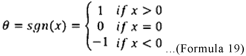
- Furthermore, with θ used as an argument, the function c(θ) is defined as follows.
Math. 20
- It should be noted that c1 and c2 in
Formula 20 are constants and are set in such a manner as to satisfy 0≤c2≤c1. The constant c1 is a constant for the change in the opening degree of theupstream expansion valve 5 in the case where the opening degree of thedownstream expansion valve 7 is increased. The constant c2 is a constant for the change in the opening degree of theupstream expansion valve 5 in the case where the opening degree of thedownstream expansion valve 7 is decreased. For example, the opening degree of theupstream expansion valve 5 may be controlled by setting c2<c1 and c2=0 such that the opening degree of theupstream expansion valve 5 is changed when the opening degree of thedownstream expansion valve 7 is increased but is not changed when the opening degree of thedownstream expansion valve 7 is decreased. - By setting c2<c1, the opening degree correction amount of the
upstream expansion valve 5 in the case where the opening degree of the downstream expansion valve is increased is larger than the opening degree correction amount of theupstream expansion valve 5 in the case where the opening degree of the downstream expansion valve is decreased, and thus the amount of the liquid refrigerant in thereceiver 6 tends to be increased. As a result, even when a modeling error or a disturbance is large, depletion of the liquid refrigerant in thereceiver 6 can be avoided. -
FIG. 12 is a diagram indicating an operation of thedownstream expansion valve 7 in a simulation performed regarding the refrigeration cycle apparatus ofEmbodiment FIG. 12 , the vertical axis represents the opening degree [pulse] of thedownstream expansion valve 7 and the horizontal axis represents time that elapses from the start of the simulation.FIG. 13 is a diagram indicating an operation of theupstream expansion valve 5 in a simulation performed regarding therefrigeration cycle apparatus 1 ofEmbodiment FIG. 13 , the vertical axis represents the opening degree [pulse] of theupstream expansion valve 5 and the horizontal axis represents time that elapses from the start of simulation.FIG. 14 is a diagram indicating a change in the refrigerant flow rate in a simulation regarding the refrigeration cycle apparatus ofEmbodiment FIG. 14 , the vertical axis represents the refrigerant flow rate Gr in therefrigerant circuit 10 and the horizontal axis represents time that elapses from the start of simulation.FIG. 15 is a diagram indicating a change in the volume of the refrigerant in the receiver in a simulation performed regarding the refrigeration cycle apparatus ofEmbodiment FIG. 15 , the vertical axis represents the volume of the liquid refrigerant stored in thereceiver 6 and the horizontal axis represents time that elapses from the start of simulation. With reference toFigs. 1 and12 to15 , results obtained by simulating the volume of the liquid refrigerant stored in thereceiver 6 under a specific condition will be described. - Electronic expansion valves were used as the
upstream expansion valve 5 and thedownstream expansion valve 7, and the reference opening degree (opening degree of the expansion valve at start time) of each of these expansion valves was set at 290 pulses. The refrigerant flow rate Gr of therefrigerant circuit 10 at that time was 225.2 [kg/h], as indicated by a dashed-dotted line inFIG. 14 , and the volume of the liquid refrigerant stored in thereceiver 6 was 0.716 [L], as indicated inFIG. 15 . An output of thesecond controller 102 is a constant. Thefirst controller 101 is operated to perform a control to cause the refrigerant flow rate to reach a target value (for example, 228.7 [kg/h] indicated by a broken line inFIG. 14 ). - First, a simulation was performed with respect to the case where the opening degree was not corrected. As indicated in
FIG. 12 , when 10 minutes elapsed, only the opening degree of thedownstream expansion valve 7 was changed from 290 pulses to 300 pulses, thereby causing the refrigerant flow rate Gr to reach the target value. When the refrigerant flow rate Gr reached the target value, the volume of the liquid refrigerant in the receiver was 0.65 [L], as indicated inFIG. 15 . Then, as indicated inFIG. 12 , when 20 minutes elapsed, an operation point of thedownstream expansion valve 7 was returned to the reference point. - Next, in the case where the opening degrees was corrected according to
Formula 1, when 30 minutes elapsed, the opening degree of thedownstream expansion valve 7 and the opening degree of theupstream expansion valve 5 were changed from 290 pulses to 297 pulses (as indicated by broken lines inFigs. 12 and 13 ) in conjunction with each other in such a manner as to satisfy the relationship ofFormula 1, thereby causing the refrigerant flow rate Gr to reach the target value. When the refrigerant flow rate reached the target value, the volume of the liquid refrigerant in thereceiver 6 was 0.735 [L], as indicated by a broken line inFIG. 15 . As indicated inFIG. 15 , a change amount (0.019 L) of the volume of the liquid refrigerant in thereceiver 6 in the case where the opening degrees was corrected according toFormula 1 was smaller than a change amount (0.066 L) of the volume of the liquid refrigerant in thereceiver 6 in the case where the opening degrees was not corrected. That is, it can be seen that in the case where the opening degrees were corrected, the function of retaining the refrigerant amount was effectively fulfilled. Then, when 40 minutes elapsed, the operation points of thedownstream expansion valve 7 and theupstream expansion valve 5 were returned to the reference points. - Finally, in the case where the opening degrees were corrected according to
Formula 11, when 50 minutes elapsed, the opening degree of thedownstream expansion valve 7 and the opening degree of theupstream expansion valve 5 were changed in conjunction with each other in such a manner as to satisfy the relationship ofFormula 10, thereby causing the refrigerant flow rate to reach the target value. In this case, the coefficient c was 0.625, and the opening degree of thedownstream expansion valve 7 was changed from 290 pulses to 298 pulses as indicated by a dashed-dotted line inFIG. 12 , and the opening degree of theupstream expansion valve 5 was changed from 290 pulses to 295 pulses as indicated inFIG. 13 . When the refrigerant flow rate Gr reached the target value, the volume of the liquid refrigerant in thereceiver 6 was 0.714 [L] as indicated by a dashed- dotted line inFIG. 15 . As illustrated inFIG. 15 , a change amount (0.002 L) of the volume of the liquid refrigerant in thereceiver 6 in the case where the opening degrees are corrected according toFormula 11 was far smaller than the change amount (0.019 L) in the case where the opening degrees were corrected according toFormula 1. Thus, the function of retaining the refrigerant amount was further improved. - The embodiments of the present invention can be freely combined within the scope of the invention. Also, regarding each embodiment, modifications or omissions can be made as appropriate. In the present invention, although the embodiments are described above in detail, the above descriptions are made by way of example regarding the embodiments and are not limiting. It should be understood that numberless modifications which are not described as examples are conceivable without departing from the scope of the present invention.
-
- 1
- refrigeration cycle apparatus
- 2
- controller
- 3
- compressor
- 4
- condenser
- 5
- upstream expansion valve
- 6
- receiver
- 7
- downstream expansion valve
- 8
- evaporator
- 9
- pipe
- 10
- refrigerant circuit
- 11
- discharge temperature sensor
- 12
- outlet temperature sensor
- 13
- high-pressure sensor
- 14
- low-pressure sensor
- 21
- control processor
- 22
- clocking device
- 23
- storage device
- 101
- first controller
- 102
- second controller
- 103, 203, 303
- opening-degree correction device
- 104, 204, 304
- refrigerant-amount retention module
- 105
- integrator
- 111
- subtractor
- 112
- adder
- 206
- coefficient determination module
- 307
- sign function block
- Gr
- refrigerant flow rate
- Sd, Su
- opening degree
- Su_tmp
- provisional value
- Suff
- correction value
Claims (10)
- A refrigeration cycle apparatus including a refrigerant circuit in which a compressor configured to compress refrigerant, a condenser, a receiver configured to store the refrigerant, and an evaporator are connected by pipes, the refrigeration cycle apparatus comprising:an upstream expansion valve whose opening degree is variable and which is provided between the condenser and the receiver in the refrigerant circuit;a downstream expansion valve whose opening degree is variable and which is provided between the receiver and the evaporator in the refrigerant circuit; anda controller configured to control the opening degree of the upstream expansion valve and the opening degree of the downstream expansion valve, wherein the controller is configured tocompute the opening degree of the downstream expansion valve and a provisional opening degree of the upstream expansion valve,compute a correction value for the opening degree of the upstream expansion valve based on at least a difference between the computed opening degree of the downstream expansion valve and an opening degree thereof that is being set, andperform a control to set the opening degree of the downstream expansion valve to the computed opening degree of the downstream expansion valve and to set the opening degree of the upstream expansion valve to an opening degree obtained by correcting the computed provisional opening degree of the upstream expansion valve by the correction value, in conjunction with the downstream expansion valve, andwherein the correction value for the opening degree of the upstream expansion valve or a correction change amount of the opening degree of the upstream expansion valve, which is a difference between the computed correction value and a previous correction value, is a value having a same sign as the difference between the opening degrees of the downstream expansion valve.
- The refrigeration cycle apparatus of claim 1,wherein the controller includesa first controller configured to change the opening degree of the downstream expansion valve as a control operation value to perform a control to cause a first control value to reach a first target control value, a second controller configured to control the provisional opening degree of the upstream expansion valve as a control operation value to make a control to cause a second control value, which is different from the first control value, to reach a second target control value, andan opening-degree correction device configured to compute the correction value for the opening degree of the upstream expansion valve based on at least the difference between the opening degrees of the downstream expansion valve, andwherein the controller is configured to compute a corrected opening degree of the upstream expansion valve by adding the control operation value for use in the control by the second controller and the correction value computed by the opening-degree correction device.
- The refrigeration cycle apparatus of claim 1 or 2, further comprising:a discharge temperature sensor configured to detect a temperature of the refrigerant discharged from the compressor;a high-pressure sensor configured to detect a pressure of the refrigerant discharged from the compressor; andan outlet temperature sensor configured to detect a temperature of the refrigerant that flows out of the condenser,wherein the controller is configured to compute the opening degree of the downstream expansion valve based on the temperature of the refrigerant that is detected by the discharge temperature sensor, and compute the provisional opening degree of the upstream expansion valve based on a degree of subcooling obtained from the pressure of the refrigerant that is detected by the high-pressure sensor and the temperature of the refrigerant that is detected by the outlet temperature sensor.
- The refrigeration cycle apparatus of any one of claims 1 to 3, wherein the controller is configured to compute the correction value for the opening degree of the upstream expansion valve based on the difference between the opening degrees of the downstream expansion valve, a set value of the opening degree of the downstream expansion valve, and a set value of the opening degree of the upstream expansion valve.
- The refrigeration cycle apparatus of any one of claims 1 to 4, wherein the correction value for the opening degree of the upstream expansion valve or an absolute value of the correction change amount of the opening degree of the upstream expansion valve increases as the opening degree being set in the upstream expansion valve increases, and decreases as the opening degree being set in the downstream expansion valve increases.
- The refrigeration cycle apparatus of any one of claims 1 to 5, wherein the correction value for or the correction change amount of the opening degree of the upstream expansion valve has an inversely proportional relationship with the opening degree being set in the downstream expansion valve, has a proportional relationship with the difference between the computed opening degree of the downstream expansion valve and the opening degree being set in the downstream expansion valve, and has a proportional relationship with the opening degree being set in the upstream expansion valve.
- The refrigeration cycle apparatus of any one of claims 1 to 6, wherein the controller is configure to compute the correction value for or the correction change amount of the opening degree of the upstream expansion valve by performing a multiplication with a predetermined coefficient.
- The refrigeration cycle apparatus of claim 7, wherein the controller is configured to determine the coefficient based on the set value of the opening degree of the upstream expansion valve, the set value of the opening degree of the downstream expansion valve, and pressure losses at the upstream expansion valve and the downstream expansion valve.
- The refrigeration cycle apparatus of claim 7, wherein a value of the coefficient in a case where the difference between the computed opening degree of the downstream expansion valve and the opening degree being set in the downstream expansion valve is positive is greater than or equal to a value of the coefficient in a case where the difference is positive.
- The refrigeration cycle apparatus of claim 9, wherein the coefficient in a case where the opening degree of the downstream expansion valve is zero.
Applications Claiming Priority (1)
| Application Number | Priority Date | Filing Date | Title |
|---|---|---|---|
| PCT/JP2020/024140 WO2021255921A1 (en) | 2020-06-19 | 2020-06-19 | Refrigeration cycle device |
Publications (3)
| Publication Number | Publication Date |
|---|---|
| EP4170265A1 true EP4170265A1 (en) | 2023-04-26 |
| EP4170265A4 EP4170265A4 (en) | 2023-07-26 |
| EP4170265B1 EP4170265B1 (en) | 2024-08-07 |
Family
ID=79267709
Family Applications (1)
| Application Number | Title | Priority Date | Filing Date |
|---|---|---|---|
| EP20940660.2A Active EP4170265B1 (en) | 2020-06-19 | 2020-06-19 | Refrigeration cycle device |
Country Status (3)
| Country | Link |
|---|---|
| EP (1) | EP4170265B1 (en) |
| JP (1) | JP7301230B2 (en) |
| WO (1) | WO2021255921A1 (en) |
Cited By (1)
| Publication number | Priority date | Publication date | Assignee | Title |
|---|---|---|---|---|
| DE102023136084A1 (en) * | 2023-12-20 | 2025-06-26 | Stiebel Eltron Gmbh & Co. Kg | Method for operating a heat pump with a vapor compression system |
Families Citing this family (1)
| Publication number | Priority date | Publication date | Assignee | Title |
|---|---|---|---|---|
| JP7297162B1 (en) * | 2022-02-03 | 2023-06-23 | 三菱電機株式会社 | Refrigeration cycle device and control method |
Family Cites Families (6)
| Publication number | Priority date | Publication date | Assignee | Title |
|---|---|---|---|---|
| JP4973078B2 (en) * | 2006-09-11 | 2012-07-11 | ダイキン工業株式会社 | Refrigeration equipment |
| JP6320639B2 (en) * | 2015-07-27 | 2018-05-09 | 三菱電機株式会社 | Air conditioner |
| EP3147592A1 (en) * | 2015-09-22 | 2017-03-29 | Honeywell spol s.r.o. | Vapor compression system with subcooling |
| JP6792057B2 (en) * | 2017-04-04 | 2020-11-25 | 三菱電機株式会社 | Refrigeration cycle equipment |
| CN111164355B (en) * | 2017-10-10 | 2024-01-05 | 三菱电机株式会社 | air conditioning unit |
| JP7233845B2 (en) * | 2018-03-27 | 2023-03-07 | 株式会社富士通ゼネラル | air conditioner |
-
2020
- 2020-06-19 JP JP2022531221A patent/JP7301230B2/en active Active
- 2020-06-19 EP EP20940660.2A patent/EP4170265B1/en active Active
- 2020-06-19 WO PCT/JP2020/024140 patent/WO2021255921A1/en not_active Ceased
Cited By (1)
| Publication number | Priority date | Publication date | Assignee | Title |
|---|---|---|---|---|
| DE102023136084A1 (en) * | 2023-12-20 | 2025-06-26 | Stiebel Eltron Gmbh & Co. Kg | Method for operating a heat pump with a vapor compression system |
Also Published As
| Publication number | Publication date |
|---|---|
| JPWO2021255921A1 (en) | 2021-12-23 |
| JP7301230B2 (en) | 2023-06-30 |
| EP4170265B1 (en) | 2024-08-07 |
| WO2021255921A1 (en) | 2021-12-23 |
| EP4170265A4 (en) | 2023-07-26 |
Similar Documents
| Publication | Publication Date | Title |
|---|---|---|
| US6711911B1 (en) | Expansion valve control | |
| CN109140826B (en) | Enthalpy-increasing heat pump, air compensation amount control method and system thereof, computer equipment and storage medium | |
| US11680738B2 (en) | CO2 refrigeration system with high pressure valve control based on coefficient of performance | |
| CN109855251B (en) | Exhaust superheat correction method and device for air conditioner, computer product and air conditioner | |
| US10107531B2 (en) | Method for controlling a chiller system | |
| US9689730B2 (en) | Estimation apparatus of heat transfer medium flow rate, heat source machine, and estimation method of heat transfer medium flow rate | |
| EP4170265B1 (en) | Refrigeration cycle device | |
| EP2420759A2 (en) | Centrifugal chiller performance evaluation system | |
| EP2413065B1 (en) | Refrigerator | |
| US11441808B2 (en) | Air-conditioning apparatus and air-conditioning method | |
| CN104913459B (en) | Refrigeration air-conditioner cold medium flux real-time control method and device | |
| CN112665112A (en) | Air conditioner, control method thereof and readable storage medium | |
| JP6741565B2 (en) | Raw material gas liquefier and control method thereof | |
| WO2013004233A1 (en) | A method for controlling operation of a vapour compression system in a subcritical and a supercritical mode | |
| CN114152002A (en) | Electronic expansion valve control method and device, computer equipment and access medium | |
| US20260050837A1 (en) | System, method, and non-transitory computer-readable recording medium storing program for device control or anomaly detection | |
| CN112665245B (en) | Load regulation control method and device of water chilling unit and water chilling unit | |
| EP3926252A1 (en) | Refrigeration cycle device | |
| CN113749480B (en) | Control method and device of refrigeration equipment, controller and refrigeration equipment | |
| CN117270593B (en) | Helium pressure control method, electronic device and readable storage medium | |
| CN118915698B (en) | Test system, method, device, equipment and storage medium | |
| JP7034389B1 (en) | Refrigeration cycle device and refrigeration cycle method | |
| US12228313B2 (en) | Refrigeration system with parallel compressors | |
| JPH03129253A (en) | Freezer | |
| Wang et al. | Load sharing strategy for parallel-operated variable speed centrifugal compressors in chillers |
Legal Events
| Date | Code | Title | Description |
|---|---|---|---|
| STAA | Information on the status of an ep patent application or granted ep patent |
Free format text: STATUS: THE INTERNATIONAL PUBLICATION HAS BEEN MADE |
|
| PUAI | Public reference made under article 153(3) epc to a published international application that has entered the european phase |
Free format text: ORIGINAL CODE: 0009012 |
|
| STAA | Information on the status of an ep patent application or granted ep patent |
Free format text: STATUS: REQUEST FOR EXAMINATION WAS MADE |
|
| 17P | Request for examination filed |
Effective date: 20221214 |
|
| AK | Designated contracting states |
Kind code of ref document: A1 Designated state(s): AL AT BE BG CH CY CZ DE DK EE ES FI FR GB GR HR HU IE IS IT LI LT LU LV MC MK MT NL NO PL PT RO RS SE SI SK SM TR |
|
| A4 | Supplementary search report drawn up and despatched |
Effective date: 20230623 |
|
| RIC1 | Information provided on ipc code assigned before grant |
Ipc: F25B 49/02 20060101ALI20230619BHEP Ipc: F25B 41/39 20210101ALI20230619BHEP Ipc: F24F 11/84 20180101ALI20230619BHEP Ipc: F25B 1/00 20060101ALI20230619BHEP Ipc: F25B 43/00 20060101AFI20230619BHEP |
|
| DAV | Request for validation of the european patent (deleted) | ||
| DAX | Request for extension of the european patent (deleted) | ||
| GRAP | Despatch of communication of intention to grant a patent |
Free format text: ORIGINAL CODE: EPIDOSNIGR1 |
|
| STAA | Information on the status of an ep patent application or granted ep patent |
Free format text: STATUS: GRANT OF PATENT IS INTENDED |
|
| INTG | Intention to grant announced |
Effective date: 20240229 |
|
| GRAS | Grant fee paid |
Free format text: ORIGINAL CODE: EPIDOSNIGR3 |
|
| GRAA | (expected) grant |
Free format text: ORIGINAL CODE: 0009210 |
|
| STAA | Information on the status of an ep patent application or granted ep patent |
Free format text: STATUS: THE PATENT HAS BEEN GRANTED |
|
| AK | Designated contracting states |
Kind code of ref document: B1 Designated state(s): AL AT BE BG CH CY CZ DE DK EE ES FI FR GB GR HR HU IE IS IT LI LT LU LV MC MK MT NL NO PL PT RO RS SE SI SK SM TR |
|
| REG | Reference to a national code |
Ref country code: GB Ref legal event code: FG4D |
|
| REG | Reference to a national code |
Ref country code: CH Ref legal event code: EP |
|
| REG | Reference to a national code |
Ref country code: DE Ref legal event code: R096 Ref document number: 602020035573 Country of ref document: DE |
|
| REG | Reference to a national code |
Ref country code: IE Ref legal event code: FG4D |
|
| REG | Reference to a national code |
Ref country code: LT Ref legal event code: MG9D |
|
| REG | Reference to a national code |
Ref country code: NL Ref legal event code: MP Effective date: 20240807 |
|
| PG25 | Lapsed in a contracting state [announced via postgrant information from national office to epo] |
Ref country code: NO Free format text: LAPSE BECAUSE OF FAILURE TO SUBMIT A TRANSLATION OF THE DESCRIPTION OR TO PAY THE FEE WITHIN THE PRESCRIBED TIME-LIMIT Effective date: 20241107 |
|
| REG | Reference to a national code |
Ref country code: AT Ref legal event code: MK05 Ref document number: 1711355 Country of ref document: AT Kind code of ref document: T Effective date: 20240807 |
|
| PG25 | Lapsed in a contracting state [announced via postgrant information from national office to epo] |
Ref country code: FI Free format text: LAPSE BECAUSE OF FAILURE TO SUBMIT A TRANSLATION OF THE DESCRIPTION OR TO PAY THE FEE WITHIN THE PRESCRIBED TIME-LIMIT Effective date: 20240807 Ref country code: NL Free format text: LAPSE BECAUSE OF FAILURE TO SUBMIT A TRANSLATION OF THE DESCRIPTION OR TO PAY THE FEE WITHIN THE PRESCRIBED TIME-LIMIT Effective date: 20240807 Ref country code: GR Free format text: LAPSE BECAUSE OF FAILURE TO SUBMIT A TRANSLATION OF THE DESCRIPTION OR TO PAY THE FEE WITHIN THE PRESCRIBED TIME-LIMIT Effective date: 20241108 Ref country code: PT Free format text: LAPSE BECAUSE OF FAILURE TO SUBMIT A TRANSLATION OF THE DESCRIPTION OR TO PAY THE FEE WITHIN THE PRESCRIBED TIME-LIMIT Effective date: 20241209 Ref country code: PL Free format text: LAPSE BECAUSE OF FAILURE TO SUBMIT A TRANSLATION OF THE DESCRIPTION OR TO PAY THE FEE WITHIN THE PRESCRIBED TIME-LIMIT Effective date: 20240807 |
|
| PG25 | Lapsed in a contracting state [announced via postgrant information from national office to epo] |
Ref country code: BG Free format text: LAPSE BECAUSE OF FAILURE TO SUBMIT A TRANSLATION OF THE DESCRIPTION OR TO PAY THE FEE WITHIN THE PRESCRIBED TIME-LIMIT Effective date: 20240807 |
|
| PG25 | Lapsed in a contracting state [announced via postgrant information from national office to epo] |
Ref country code: LV Free format text: LAPSE BECAUSE OF FAILURE TO SUBMIT A TRANSLATION OF THE DESCRIPTION OR TO PAY THE FEE WITHIN THE PRESCRIBED TIME-LIMIT Effective date: 20240807 |
|
| PG25 | Lapsed in a contracting state [announced via postgrant information from national office to epo] |
Ref country code: IS Free format text: LAPSE BECAUSE OF FAILURE TO SUBMIT A TRANSLATION OF THE DESCRIPTION OR TO PAY THE FEE WITHIN THE PRESCRIBED TIME-LIMIT Effective date: 20241207 Ref country code: AT Free format text: LAPSE BECAUSE OF FAILURE TO SUBMIT A TRANSLATION OF THE DESCRIPTION OR TO PAY THE FEE WITHIN THE PRESCRIBED TIME-LIMIT Effective date: 20240807 |
|
| PG25 | Lapsed in a contracting state [announced via postgrant information from national office to epo] |
Ref country code: HR Free format text: LAPSE BECAUSE OF FAILURE TO SUBMIT A TRANSLATION OF THE DESCRIPTION OR TO PAY THE FEE WITHIN THE PRESCRIBED TIME-LIMIT Effective date: 20240807 |
|
| PG25 | Lapsed in a contracting state [announced via postgrant information from national office to epo] |
Ref country code: ES Free format text: LAPSE BECAUSE OF FAILURE TO SUBMIT A TRANSLATION OF THE DESCRIPTION OR TO PAY THE FEE WITHIN THE PRESCRIBED TIME-LIMIT Effective date: 20240807 Ref country code: RS Free format text: LAPSE BECAUSE OF FAILURE TO SUBMIT A TRANSLATION OF THE DESCRIPTION OR TO PAY THE FEE WITHIN THE PRESCRIBED TIME-LIMIT Effective date: 20241107 |
|
| PG25 | Lapsed in a contracting state [announced via postgrant information from national office to epo] |
Ref country code: RS Free format text: LAPSE BECAUSE OF FAILURE TO SUBMIT A TRANSLATION OF THE DESCRIPTION OR TO PAY THE FEE WITHIN THE PRESCRIBED TIME-LIMIT Effective date: 20241107 Ref country code: PT Free format text: LAPSE BECAUSE OF FAILURE TO SUBMIT A TRANSLATION OF THE DESCRIPTION OR TO PAY THE FEE WITHIN THE PRESCRIBED TIME-LIMIT Effective date: 20241209 Ref country code: PL Free format text: LAPSE BECAUSE OF FAILURE TO SUBMIT A TRANSLATION OF THE DESCRIPTION OR TO PAY THE FEE WITHIN THE PRESCRIBED TIME-LIMIT Effective date: 20240807 Ref country code: NO Free format text: LAPSE BECAUSE OF FAILURE TO SUBMIT A TRANSLATION OF THE DESCRIPTION OR TO PAY THE FEE WITHIN THE PRESCRIBED TIME-LIMIT Effective date: 20241107 Ref country code: NL Free format text: LAPSE BECAUSE OF FAILURE TO SUBMIT A TRANSLATION OF THE DESCRIPTION OR TO PAY THE FEE WITHIN THE PRESCRIBED TIME-LIMIT Effective date: 20240807 Ref country code: LV Free format text: LAPSE BECAUSE OF FAILURE TO SUBMIT A TRANSLATION OF THE DESCRIPTION OR TO PAY THE FEE WITHIN THE PRESCRIBED TIME-LIMIT Effective date: 20240807 Ref country code: IS Free format text: LAPSE BECAUSE OF FAILURE TO SUBMIT A TRANSLATION OF THE DESCRIPTION OR TO PAY THE FEE WITHIN THE PRESCRIBED TIME-LIMIT Effective date: 20241207 Ref country code: HR Free format text: LAPSE BECAUSE OF FAILURE TO SUBMIT A TRANSLATION OF THE DESCRIPTION OR TO PAY THE FEE WITHIN THE PRESCRIBED TIME-LIMIT Effective date: 20240807 Ref country code: GR Free format text: LAPSE BECAUSE OF FAILURE TO SUBMIT A TRANSLATION OF THE DESCRIPTION OR TO PAY THE FEE WITHIN THE PRESCRIBED TIME-LIMIT Effective date: 20241108 Ref country code: FI Free format text: LAPSE BECAUSE OF FAILURE TO SUBMIT A TRANSLATION OF THE DESCRIPTION OR TO PAY THE FEE WITHIN THE PRESCRIBED TIME-LIMIT Effective date: 20240807 Ref country code: ES Free format text: LAPSE BECAUSE OF FAILURE TO SUBMIT A TRANSLATION OF THE DESCRIPTION OR TO PAY THE FEE WITHIN THE PRESCRIBED TIME-LIMIT Effective date: 20240807 Ref country code: BG Free format text: LAPSE BECAUSE OF FAILURE TO SUBMIT A TRANSLATION OF THE DESCRIPTION OR TO PAY THE FEE WITHIN THE PRESCRIBED TIME-LIMIT Effective date: 20240807 Ref country code: AT Free format text: LAPSE BECAUSE OF FAILURE TO SUBMIT A TRANSLATION OF THE DESCRIPTION OR TO PAY THE FEE WITHIN THE PRESCRIBED TIME-LIMIT Effective date: 20240807 |
|
| PG25 | Lapsed in a contracting state [announced via postgrant information from national office to epo] |
Ref country code: DK Free format text: LAPSE BECAUSE OF FAILURE TO SUBMIT A TRANSLATION OF THE DESCRIPTION OR TO PAY THE FEE WITHIN THE PRESCRIBED TIME-LIMIT Effective date: 20240807 Ref country code: SM Free format text: LAPSE BECAUSE OF FAILURE TO SUBMIT A TRANSLATION OF THE DESCRIPTION OR TO PAY THE FEE WITHIN THE PRESCRIBED TIME-LIMIT Effective date: 20240807 |
|
| PG25 | Lapsed in a contracting state [announced via postgrant information from national office to epo] |
Ref country code: EE Free format text: LAPSE BECAUSE OF FAILURE TO SUBMIT A TRANSLATION OF THE DESCRIPTION OR TO PAY THE FEE WITHIN THE PRESCRIBED TIME-LIMIT Effective date: 20240807 |
|
| PG25 | Lapsed in a contracting state [announced via postgrant information from national office to epo] |
Ref country code: CZ Free format text: LAPSE BECAUSE OF FAILURE TO SUBMIT A TRANSLATION OF THE DESCRIPTION OR TO PAY THE FEE WITHIN THE PRESCRIBED TIME-LIMIT Effective date: 20240807 |
|
| PG25 | Lapsed in a contracting state [announced via postgrant information from national office to epo] |
Ref country code: SK Free format text: LAPSE BECAUSE OF FAILURE TO SUBMIT A TRANSLATION OF THE DESCRIPTION OR TO PAY THE FEE WITHIN THE PRESCRIBED TIME-LIMIT Effective date: 20240807 |
|
| REG | Reference to a national code |
Ref country code: DE Ref legal event code: R097 Ref document number: 602020035573 Country of ref document: DE |
|
| PLBE | No opposition filed within time limit |
Free format text: ORIGINAL CODE: 0009261 |
|
| STAA | Information on the status of an ep patent application or granted ep patent |
Free format text: STATUS: NO OPPOSITION FILED WITHIN TIME LIMIT |
|
| PGFP | Annual fee paid to national office [announced via postgrant information from national office to epo] |
Ref country code: DE Payment date: 20250429 Year of fee payment: 6 |
|
| 26N | No opposition filed |
Effective date: 20250508 |
|
| PG25 | Lapsed in a contracting state [announced via postgrant information from national office to epo] |
Ref country code: SE Free format text: LAPSE BECAUSE OF FAILURE TO SUBMIT A TRANSLATION OF THE DESCRIPTION OR TO PAY THE FEE WITHIN THE PRESCRIBED TIME-LIMIT Effective date: 20240807 |
|
| P01 | Opt-out of the competence of the unified patent court (upc) registered |
Free format text: CASE NUMBER: UPC_APP_4946_4170265/2025 Effective date: 20250827 |
|
| REG | Reference to a national code |
Ref country code: CH Ref legal event code: H13 Free format text: ST27 STATUS EVENT CODE: U-0-0-H10-H13 (AS PROVIDED BY THE NATIONAL OFFICE) Effective date: 20260127 |
|
| PG25 | Lapsed in a contracting state [announced via postgrant information from national office to epo] |
Ref country code: IT Free format text: LAPSE BECAUSE OF FAILURE TO SUBMIT A TRANSLATION OF THE DESCRIPTION OR TO PAY THE FEE WITHIN THE PRESCRIBED TIME-LIMIT Effective date: 20240807 |
|
| PG25 | Lapsed in a contracting state [announced via postgrant information from national office to epo] |
Ref country code: MC Free format text: LAPSE BECAUSE OF FAILURE TO SUBMIT A TRANSLATION OF THE DESCRIPTION OR TO PAY THE FEE WITHIN THE PRESCRIBED TIME-LIMIT Effective date: 20240807 |
|
| PG25 | Lapsed in a contracting state [announced via postgrant information from national office to epo] |
Ref country code: LU Free format text: LAPSE BECAUSE OF NON-PAYMENT OF DUE FEES Effective date: 20250619 |
|
| GBPC | Gb: european patent ceased through non-payment of renewal fee |
Effective date: 20250619 |
|
| REG | Reference to a national code |
Ref country code: BE Ref legal event code: MM Effective date: 20250630 |
|
| PG25 | Lapsed in a contracting state [announced via postgrant information from national office to epo] |
Ref country code: GB Free format text: LAPSE BECAUSE OF NON-PAYMENT OF DUE FEES Effective date: 20250619 |
|
| PG25 | Lapsed in a contracting state [announced via postgrant information from national office to epo] |
Ref country code: IE Free format text: LAPSE BECAUSE OF NON-PAYMENT OF DUE FEES Effective date: 20250619 |
|
| PG25 | Lapsed in a contracting state [announced via postgrant information from national office to epo] |
Ref country code: RO Free format text: LAPSE BECAUSE OF FAILURE TO SUBMIT A TRANSLATION OF THE DESCRIPTION OR TO PAY THE FEE WITHIN THE PRESCRIBED TIME-LIMIT Effective date: 20240807 Ref country code: BE Free format text: LAPSE BECAUSE OF NON-PAYMENT OF DUE FEES Effective date: 20250630 |
|
| PG25 | Lapsed in a contracting state [announced via postgrant information from national office to epo] |
Ref country code: FR Free format text: LAPSE BECAUSE OF NON-PAYMENT OF DUE FEES Effective date: 20250630 |
|
| PG25 | Lapsed in a contracting state [announced via postgrant information from national office to epo] |
Ref country code: CH Free format text: LAPSE BECAUSE OF NON-PAYMENT OF DUE FEES Effective date: 20250630 |