EP4170236B1 - Method for pressure monitoring a pressure-dependent process and pressure sensor - Google Patents
Method for pressure monitoring a pressure-dependent process and pressure sensor Download PDFInfo
- Publication number
- EP4170236B1 EP4170236B1 EP21203458.1A EP21203458A EP4170236B1 EP 4170236 B1 EP4170236 B1 EP 4170236B1 EP 21203458 A EP21203458 A EP 21203458A EP 4170236 B1 EP4170236 B1 EP 4170236B1
- Authority
- EP
- European Patent Office
- Prior art keywords
- pressure
- measured
- status
- value
- filtered
- Prior art date
- Legal status (The legal status is an assumption and is not a legal conclusion. Google has not performed a legal analysis and makes no representation as to the accuracy of the status listed.)
- Active
Links
Images

Classifications
-
- F—MECHANICAL ENGINEERING; LIGHTING; HEATING; WEAPONS; BLASTING
- F23—COMBUSTION APPARATUS; COMBUSTION PROCESSES
- F23N—REGULATING OR CONTROLLING COMBUSTION
- F23N5/00—Systems for controlling combustion
- F23N5/24—Preventing development of abnormal or undesired conditions, i.e. safety arrangements
- F23N5/242—Preventing development of abnormal or undesired conditions, i.e. safety arrangements using electronic means
-
- F—MECHANICAL ENGINEERING; LIGHTING; HEATING; WEAPONS; BLASTING
- F23—COMBUSTION APPARATUS; COMBUSTION PROCESSES
- F23N—REGULATING OR CONTROLLING COMBUSTION
- F23N1/00—Regulating fuel supply
- F23N1/02—Regulating fuel supply conjointly with air supply
- F23N1/022—Regulating fuel supply conjointly with air supply using electronic means
-
- F—MECHANICAL ENGINEERING; LIGHTING; HEATING; WEAPONS; BLASTING
- F23—COMBUSTION APPARATUS; COMBUSTION PROCESSES
- F23N—REGULATING OR CONTROLLING COMBUSTION
- F23N2225/00—Measuring
- F23N2225/04—Measuring pressure
Definitions
- the invention relates to a method for pressure monitoring a pressure-dependent process. Further on, the invention relates to a pressure sensor.
- pressure switches are used to provide pressure monitoring.
- Several pressure switches are needed to monitor if the pressure to be monitored during operation of the pressure-dependent processes is above or below certain pressure levels. For each pressure level an individual pressure switch is needed. This requires high hardware and installation costs.
- EP 1 000 301 B1 , US 5,732,691 A , US 6,006,167 A and US 2009/0104573 A1 show processes using pressure switches.
- JP H06 229803 A , JP H06 229804 A and EP 3 118 030 A1 disclose further prior art.
- a novel method for pressure monitoring a pressure-dependent process and a novel pressure sensor are provided allowing a pressure monitoring with reduced hardware and installation costs.
- the invention provides a method for pressure monitoring a pressure-dependent process according to claim 1.
- the novel method for pressure monitoring a pressure-dependent process comprises the following steps: Measuring over time a pressure of the pressure-dependent process.
- Processing the measured pressure by determining if the measured pressure or a filtered pressure obtained from the measured pressure is inside or outside defined pressure ranges, each pressure range being defined by a respective lower limit and by a respective upper limit.
- the pressure monitoring signal has a first value or first status if the measured pressure or the filtered pressure is inside a respective pressure range.
- the pressure monitoring signal has a second value or second status if the measured pressure or the filtered pressure is outside a respective pressure range violating a safety relevant limit.
- the pressure monitoring signal has a third value or third status if the measured pressure or the filtered pressure is outside a respective pressure range violating a non-safety relevant limit.
- the novel method allows a pressure monitoring with reduced hardware and installation costs.
- the pressure monitoring signal has the first value or first status if the measured or filtered pressure is within a respective time interval inside the respective pressure range.
- the pressure monitoring signal has the second value or second status if the measured pressure or the filtered pressure is within a respective time interval outside the respective pressure range violating a safety relevant limit.
- the pressure monitoring signal has the third value or third status if the measured pressure or the filtered pressure is within a respective time interval outside a respective pressure range violating a non-safety relevant limit. This is preferred if a feedback signal of the pressure-dependent process being indicative about operational time intervals of the pressure-dependent process is available when measuring the pressure.
- the pressure dependent process is continued unchanged.
- the pressure monitoring signal has the second value or second status the pressure dependent process is stopped.
- the pressure monitoring signal has the third value or third status
- the pressure dependent process is continued unchanged or the pressure dependent process is continued by adapting at least one process parameter of the pressure dependent process or the pressure dependent process is stopped.
- the action to be taken if the if the pressure monitoring signal has the third value or third status may depend on the respective pressure range and/or the respective non-safety relevant limit. This allows a very preferred operation of the pressure-dependent process on basis of the pressure monitoring.
- the pressure sensor for monitoring a pressure dependent process is defined in claim 10 and comprises: A measuring unit being configured to measure over the time a pressure of the pressure-dependent process.
- a processing unit being configured to process the measured pressure by determining if the measured pressure or a filtered pressure obtained from the measured pressure is inside or outside defined pressure ranges and to generate a pressure monitoring signal in such a way that the pressure monitoring signal has a first value or first status if the measured pressure or the filtered pressure is inside a respective pressure range, that the pressure monitoring signal has a second value or second status if the measured pressure or the filtered pressure is outside a respective pressure range violating a safety relevant limit, and that the pressure monitoring signal has a third value or third status if the measured pressure or the filtered pressure is outside a respective pressure range violating a non-safety relevant limit.
- the pressure sensor allows to monitor several pressure levels and eliminates the need of individual pressure switches to monitor the several pressure levels.
- the invention relates to a method for pressure monitoring a pressure-dependent process and further to a pressure senor for pressure monitoring a pressure-dependent process.
- the pressure-dependent process may be a combustion process of a gas burner appliance combusting a gas/air mixture which is provided by mixing gas with air.
- the pressure to be monitored may be the pressure of the gas or the pressure of the air or the pressure of the gas/air mixture.
- the gas to be combusted may be natural gas, coal gas, methane, propane, hydrogen or the like. As absolute pressure may be measured as pressure of the pressure-dependent process.
- the invention can be used in connection with other pressure-dependent processes to monitor the pressure of process medium like a gaseous process medium, a liquid process medium, a solid process medium or a plasma process medium.
- the pressure monitoring method comprises the following steps: A measuring step to measure over time a pressure of the pressure-dependent process.
- a processing step to process the measured pressure by determining if the measured pressure or a filtered pressure obtained from the measured pressure is inside or outside defined pressure ranges, each pressure range being defined by a respective lower limit and by a respective upper limit.
- a generating step to generate a pressure monitoring signal in such a way that i) the pressure monitoring signal has a first value or first status if the measured pressure or the filtered pressure is inside a respective pressure range, that ii) the pressure monitoring signal has a second value or second status if the measured pressure or the filtered pressure is outside a respective pressure range violating a safety relevant limit, and that iii) the pressure monitoring signal has a third value or third status if the measured pressure or the filtered pressure is outside a respective pressure range violating a non-safety relevant limit.
- curve 10 of Figure 1 shows a pressure signal of a pressure-dependent process measured over time t.
- curve 10 of Figure 1 may show a filtered pressure signal obtained from the measured pressure signal.
- Figure 1 further shows pressure ranges 11, 12, 13, and 14.
- the pressure range 11 is defined by a respective lower limit A and by a respective upper limit B.
- the pressure range 12 is defined by a respective lower limit C and by a respective upper limit D.
- the pressure range 13 is defined by a respective lower limit E and by a respective upper limit F.
- the pressure range 14 is defined by a respective lower limit G and by a respective upper limit H.
- the pressure monitoring signal has the first value or first status. If the pressure monitoring signal has the first value or first status, the pressure dependent process is continued unchanged.
- the pressure monitoring signal has the second value or second status. If the pressure monitoring signal has the second value or second status, the pressure dependent process is stopped immediately.
- a safety relevant limit is the lower limit A of the pressure range 11. If it would be determined that the pressure signal 10 would be below the safety relevant limit A, the pressure monitoring signal would have the second value or second status and the the pressure dependent process would be stopped immediately.
- the area 15 in Fig. 1 illustrates a safety relevant area. If the pressure signal 10, namely either the measured pressure signal or the filtered pressure signal obtained from the measured pressure signal, would be within this safety relevant area 15, the pressure monitoring signal would have the second value or second status and the pressure dependent process would be stopped.
- the pressure monitoring signal has the third value or third status. If the pressure monitoring signal has the third value or third status, the pressure dependent process is continued unchanged or by adapting at least one process parameter or the pressure dependent process is stopped. In Figure 1 such a non-safety relevant limit would be the limits B to H. If it would be determined that the pressure signal 10 would above the limit B and below the limit C, and/or above the limit D and below the limit E, and/or above the limit F and below the limit G, the pressure monitoring signal would have the third value or third status. The pressure dependent process may then be continued unchanged or may then be continued by adapting at least one process parameter or the pressure dependent process is stopped, depending on the respective limit and/or depending on the duration of the violation of the respective limit.
- the pressure dependent process may be continued unchanged in view of the brief violation of the limit C in section 16 of the pressure signal 10 and/or the pressure dependent process may be continued by adapting at least one process parameter in view of the long violation of the limits F and G in section 17 of the pressure signal 10.
- the method illustrated in Figure 1 is preferably used if a feedback signal of the pressure-dependent process being indicative about operational time intervals of the pressure-dependent process is not available when measuring the pressure.
- the curve 20 of Figure 12 shows a pressure signal of a pressure-dependent process measured over time t.
- curve 20 of Figure 2 may show a filtered pressure signal obtained from the measured pressure signal.
- Figure 2 further shows pressure ranges 21, 22, 23, and 24.
- the pressure range 21 is defined by a respective lower limit A and by a respective upper limit B and is valid for time interval between times t1 and t2.
- the pressure range 22 is defined by a respective lower limit C and by a respective upper limit D and is valid for time interval between times t3 and t4.
- the pressure range 23 is defined by a respective lower limit E and by a respective upper limit F and is valid for time interval between times t5 and t6.
- the pressure range 24 is defined by a respective lower limit G and by a respective upper limit H and is valid for time interval between times t7 and t8.
- the pressure monitoring signal has the first value or first status. If the pressure monitoring signal has the first value or first status, the pressure dependent process is continued unchanged.
- the pressure monitoring signal has the second value or second status and the pressure dependent process is stopped immediately.
- a safety relevant limit would be the lower limit A of the pressure range 21. If it would be determined that the pressure signal 20 would within the time interval t1-t2 or within any other time interval below the safety relevant limit A, the pressure monitoring signal would have the second value or second status and the pressure dependent process would be stopped.
- the area 25 in Fig. 2 illustrates a safety relevant area. If the pressure signal 20 would be at any time within this safety relevant area 25, the pressure monitoring signal would have the second value or second status and the pressure dependent process would be stopped immediately.
- the pressure monitoring signal has the third value or third status. If the pressure monitoring signal has the third value or third status, the pressure dependent process may be continued unchanged or may be stopped or may be continued by adapting at least one process parameters of the pressure dependent process.
- such a non-safety relevant limit would be the limits B to H. If it would be determined that the pressure signal 20 would be in time interval t1-t2 above limits B, and/or in time interval t3-t4 the pressure signal 20 would be below limit C or above limit D, and/or in time interval t5-t6 the pressure signal 10 would be below limit D or above limit E, and/or in time interval t7-t8 the pressure signal 10 would be below limit G or above limit H, the pressure monitoring signal would have the third value or third status.
- the pressure dependent process may then be continued unchanged or may then be continued by adapting at least one process parameter or the pressure dependent process is stopped, depending on the respective limit and/or depending on the duration of the violation of the respective limit.
- the pressure dependent process may be continued unchanged in view of the brief violation of the limit C in time interval t3-t4 and/or the pressure dependent process may be continued by adapting at least one process parameter in view of the long violation of the limit E in time-interval t5-t6.
- the pressure of the pressure-dependent process is measuring over the time t.
- the pressure signal 10, 20 is a function of time. This means that the value or status of pressure monitoring signal obtained on basis of the pressure signal 10, 20 may change over the time t because the processing step and generating step are executed over the time on basis of the pressure signal 10, 20.
- the present disclosure provides further a pressure sensor 30 for monitoring a pressure-dependent process.
- the pressure sensor 30 comprises a measuring unit 31 being configured to measure over the time a pressure of the pressure-dependent process.
- the pressure sensor 30 may comprise one measuring unit 31 or several measuring units 31. If the pressure sensor 30 comprises several measuring units 31, e. g. two measuring units 31, each measuring unit 31 may measure the pressure to provide redundancy.
- the measurement values of the measuring units 31 may be used to calculate an average value. The average value may that be used in the processing step.
- the pressure sensor 30 further comprises a memory unit 32 for storing at least the defined pressure ranges, each pressure range being defined by a respective lower limit and by a respective upper limit.
- the pressure sensor 30 further comprises a processing unit 33 being configured to process the measured pressure by determining if the measured pressure or a filtered pressure obtained from the measured pressure is inside or outside a respective pressure range and to generate a pressure monitoring signal 34.
- the pressure monitoring signal 34 has a first value or first status if the measured pressure or the filtered pressure is inside a respective pressure range.
- the pressure monitoring signal has a second value or second status if the measured pressure or the filtered pressure is outside a respective pressure range violating a safety relevant limit.
- the pressure monitoring signal has a third value or third status if the measured pressure or the filtered pressure is outside a respective pressure range violating a non-safety relevant limit.
- the pressure monitoring signal 34 is used by a control system 35 to control the pressure-dependent process. If the pressure monitoring signal 34 has the first value or first status, the pressure dependent process is continued unchanged. Preferably, if the pressure monitoring signal 34 has the second value or second status the pressure dependent process is stopped immediately. Preferably, if the pressure monitoring signal 34 has the third value or third status, the pressure dependent process is continued unchanged or the pressure dependent process 35 is continued by adapting at least one process parameter of the pressure dependent process or the pressure dependent process 35 is stopped.
- the method illustrated in Figure 2 is preferably used. If the feedback signal 36 is not available, the method illustrated in Figure 1 is preferably used.
- the basic concept of the invention is to provide a pressure monitoring which allows to replace several pressure switches with one pressure sensor.
- the pressure sensor provides as output the pressure monitoring signal 34 indicating a valid or invalid pressure state.
- Pressure monitoring can be provided at reduced hardware and installation costs.
- State conditions for the pressure sensor output, namely for the pressure monitoring signal 34, are defined by parameters to be stored in memory unit 35.
- At least defined pressure ranges and preferably also time intervals associated with the pressure ranges are stored in memory unit 35.
- With one intelligent pressure sensor 30 the function of many pressure switches can be covered. With one intelligent pressure sensor 30 a pressure can be measured and it can be verified that the measured pressure is in expected pressure ranges in expected time intervals. By the changing the of parameters stored in the non-volatile memory unit, the sensor 30 can be easily configured to different applications.
Landscapes
- Engineering & Computer Science (AREA)
- Chemical & Material Sciences (AREA)
- Combustion & Propulsion (AREA)
- Mechanical Engineering (AREA)
- General Engineering & Computer Science (AREA)
- Measuring Fluid Pressure (AREA)
Description
- The invention relates to a method for pressure monitoring a pressure-dependent process. Further on, the invention relates to a pressure sensor.
- In pressure-dependent processes like combustion processes pressure switches are used to provide pressure monitoring. Several pressure switches are needed to monitor if the pressure to be monitored during operation of the pressure-dependent processes is above or below certain pressure levels. For each pressure level an individual pressure switch is needed. This requires high hardware and installation costs.
-
EP 1 000 301 B1US 5,732,691 A ,US 6,006,167 A andUS 2009/0104573 A1 show processes using pressure switches.JP H06 229803 A JP H06 229804 A EP 3 118 030 A1 disclose further prior art. - Against this background, a novel method for pressure monitoring a pressure-dependent process and a novel pressure sensor are provided allowing a pressure monitoring with reduced hardware and installation costs.
- The invention provides a method for pressure monitoring a pressure-dependent process according to
claim 1. - The novel method for pressure monitoring a pressure-dependent process comprises the following steps:
Measuring over time a pressure of the pressure-dependent process. - Processing the measured pressure by determining if the measured pressure or a filtered pressure obtained from the measured pressure is inside or outside defined pressure ranges, each pressure range being defined by a respective lower limit and by a respective upper limit.
- Generating a pressure monitoring signal.
- The pressure monitoring signal has a first value or first status if the measured pressure or the filtered pressure is inside a respective pressure range.
- The pressure monitoring signal has a second value or second status if the measured pressure or the filtered pressure is outside a respective pressure range violating a safety relevant limit.
- The pressure monitoring signal has a third value or third status if the measured pressure or the filtered pressure is outside a respective pressure range violating a non-safety relevant limit.
- The novel method allows a pressure monitoring with reduced hardware and installation costs.
- Preferably, during the processing step it is determined if the measured pressure or the filtered pressure is within defined time intervals inside or outside respective pressure ranges associated with the respective time intervals. Then, the pressure monitoring signal has the first value or first status if the measured or filtered pressure is within a respective time interval inside the respective pressure range. The pressure monitoring signal has the second value or second status if the measured pressure or the filtered pressure is within a respective time interval outside the respective pressure range violating a safety relevant limit. Then, the pressure monitoring signal has the third value or third status if the measured pressure or the filtered pressure is within a respective time interval outside a respective pressure range violating a non-safety relevant limit. This is preferred if a feedback signal of the pressure-dependent process being indicative about operational time intervals of the pressure-dependent process is available when measuring the pressure.
- Preferably, if the pressure monitoring signal has the first value or first status, the pressure dependent process is continued unchanged. Preferably, if the pressure monitoring signal has the second value or second status the pressure dependent process is stopped. Preferably, if the pressure monitoring signal has the third value or third status, the pressure dependent process is continued unchanged or the pressure dependent process is continued by adapting at least one process parameter of the pressure dependent process or the pressure dependent process is stopped. The action to be taken if the if the pressure monitoring signal has the third value or third status may depend on the respective pressure range and/or the respective non-safety relevant limit. This allows a very preferred operation of the pressure-dependent process on basis of the pressure monitoring.
- The pressure sensor for monitoring a pressure dependent process is defined in
claim 10 and comprises: A measuring unit being configured to measure over the time a pressure of the pressure-dependent process. A memory unit for storing defined pressure ranges, each pressure range being defined by a respective lower limit and by a respective upper limit. A processing unit being configured to process the measured pressure by determining if the measured pressure or a filtered pressure obtained from the measured pressure is inside or outside defined pressure ranges and to generate a pressure monitoring signal in such a way that the pressure monitoring signal has a first value or first status if the measured pressure or the filtered pressure is inside a respective pressure range, that the pressure monitoring signal has a second value or second status if the measured pressure or the filtered pressure is outside a respective pressure range violating a safety relevant limit, and that the pressure monitoring signal has a third value or third status if the measured pressure or the filtered pressure is outside a respective pressure range violating a non-safety relevant limit. The pressure sensor allows to monitor several pressure levels and eliminates the need of individual pressure switches to monitor the several pressure levels. - Preferred developments of the invention are provided by the dependent claims and the description which follows. Exemplary embodiments are explained in more detail on the basis of the drawing, in which:
- Figure 1
- shows a time diagram illustrating of the method for pressure monitoring a pressure-dependent process,
- Figure 2
- shows a time diagram illustrating of a preferred further development of the method for pressure monitoring a pressure-dependent process,
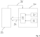
- Figure 3
- shows a block diagram illustrating a control system for a pressure-dependent process using a pressure sensor for pressure monitoring the pressure-dependent process.
- The invention relates to a method for pressure monitoring a pressure-dependent process and further to a pressure senor for pressure monitoring a pressure-dependent process.
- The pressure-dependent process may be a combustion process of a gas burner appliance combusting a gas/air mixture which is provided by mixing gas with air. The pressure to be monitored may be the pressure of the gas or the pressure of the air or the pressure of the gas/air mixture. The gas to be combusted may be natural gas, coal gas, methane, propane, hydrogen or the like. As absolute pressure may be measured as pressure of the pressure-dependent process.
- The invention can be used in connection with other pressure-dependent processes to monitor the pressure of process medium like a gaseous process medium, a liquid process medium, a solid process medium or a plasma process medium.
- The pressure monitoring method comprises the following steps:
A measuring step to measure over time a pressure of the pressure-dependent process. - A processing step to process the measured pressure by determining if the measured pressure or a filtered pressure obtained from the measured pressure is inside or outside defined pressure ranges, each pressure range being defined by a respective lower limit and by a respective upper limit.
- A generating step to generate a pressure monitoring signal in such a way that i) the pressure monitoring signal has a first value or first status if the measured pressure or the filtered pressure is inside a respective pressure range, that ii) the pressure monitoring signal has a second value or second status if the measured pressure or the filtered pressure is outside a respective pressure range violating a safety relevant limit, and that iii) the pressure monitoring signal has a third value or third status if the measured pressure or the filtered pressure is outside a respective pressure range violating a non-safety relevant limit.
- Further details of the invention will be described with refence to the drawings.
- The
curve 10 ofFigure 1 shows a pressure signal of a pressure-dependent process measured over time t. Alternatively,curve 10 ofFigure 1 may show a filtered pressure signal obtained from the measured pressure signal. -
Figure 1 further showspressure ranges pressure range 11 is defined by a respective lower limit A and by a respective upper limit B. Thepressure range 12 is defined by a respective lower limit C and by a respective upper limit D. Thepressure range 13 is defined by a respective lower limit E and by a respective upper limit F. Thepressure range 14 is defined by a respective lower limit G and by a respective upper limit H. - If the
pressure signal 10, namely either the measured pressure signal or the filtered pressure signal obtained from the measured pressure signal, is inside arespective pressure ranges - If the
pressure signal 10, namely either the measured pressure signal or the filtered pressure signal obtained from the measured pressure signal, is outside arespective pressure range Figure 1 such a safety relevant limit is the lower limit A of thepressure range 11. If it would be determined that thepressure signal 10 would be below the safety relevant limit A, the pressure monitoring signal would have the second value or second status and the the pressure dependent process would be stopped immediately. The area 15 inFig. 1 illustrates a safety relevant area. If thepressure signal 10, namely either the measured pressure signal or the filtered pressure signal obtained from the measured pressure signal, would be within this safety relevant area 15, the pressure monitoring signal would have the second value or second status and the pressure dependent process would be stopped. - If the
pressure signal 10, namely either the measured pressure signal or the filtered pressure signal obtained from the measured pressure signal, is outside a respective pressure ranges 11, 12, 13, 14 and violates a non-safety relevant limit, the pressure monitoring signal has the third value or third status. If the pressure monitoring signal has the third value or third status, the pressure dependent process is continued unchanged or by adapting at least one process parameter or the pressure dependent process is stopped. InFigure 1 such a non-safety relevant limit would be the limits B to H. If it would be determined that thepressure signal 10 would above the limit B and below the limit C, and/or above the limit D and below the limit E, and/or above the limit F and below the limit G, the pressure monitoring signal would have the third value or third status. The pressure dependent process may then be continued unchanged or may then be continued by adapting at least one process parameter or the pressure dependent process is stopped, depending on the respective limit and/or depending on the duration of the violation of the respective limit. - In
Figure 1 , e. g. the pressure dependent process may be continued unchanged in view of the brief violation of the limit C in section 16 of thepressure signal 10 and/or the pressure dependent process may be continued by adapting at least one process parameter in view of the long violation of the limits F and G insection 17 of thepressure signal 10. - The method illustrated in
Figure 1 is preferably used if a feedback signal of the pressure-dependent process being indicative about operational time intervals of the pressure-dependent process is not available when measuring the pressure. - If such a feedback signal of the pressure-dependent process being indicative about operational time intervals of the pressure-dependent process is available, the method illustrated in
Figure 2 is preferably used. - The curve 20 of Figure 12 shows a pressure signal of a pressure-dependent process measured over time t.
- Alternatively, curve 20 of
Figure 2 may show a filtered pressure signal obtained from the measured pressure signal. -
Figure 2 further shows pressure ranges 21, 22, 23, and 24. The pressure range 21 is defined by a respective lower limit A and by a respective upper limit B and is valid for time interval between times t1 and t2. Thepressure range 22 is defined by a respective lower limit C and by a respective upper limit D and is valid for time interval between times t3 and t4. Thepressure range 23 is defined by a respective lower limit E and by a respective upper limit F and is valid for time interval between times t5 and t6. Thepressure range 24 is defined by a respective lower limit G and by a respective upper limit H and is valid for time interval between times t7 and t8. - If the pressure signal 20, namely either the measured pressure signal or the filtered pressure signal obtained from the measured pressure signal, is within a respective time interval t1-t2 and/or t3-t4 and/or t5-t6 and/or t7-t8 inside the
respective pressure range - If the pressure signal 20, namely either the measured pressure signal or the filtered pressure signal obtained from the measured pressure signal, is within a respective time interval outside the respective pressure range violating a safety relevant limit, the pressure monitoring signal has the second value or second status and the pressure dependent process is stopped immediately. In
Figure 2 such a safety relevant limit would be the lower limit A of the pressure range 21. If it would be determined that the pressure signal 20 would within the time interval t1-t2 or within any other time interval below the safety relevant limit A, the pressure monitoring signal would have the second value or second status and the pressure dependent process would be stopped. Thearea 25 inFig. 2 illustrates a safety relevant area. If the pressure signal 20 would be at any time within this safetyrelevant area 25, the pressure monitoring signal would have the second value or second status and the pressure dependent process would be stopped immediately. - If the pressure signal 20, namely either the measured pressure signal or the filtered pressure signal obtained from the measured pressure signal, is within a respective time interval outside the respective pressure range violating a non-safety relevant limit, the pressure monitoring signal has the third value or third status. If the pressure monitoring signal has the third value or third status, the pressure dependent process may be continued unchanged or may be stopped or may be continued by adapting at least one process parameters of the pressure dependent process.
- In
Figure 2 such a non-safety relevant limit would be the limits B to H. If it would be determined that the pressure signal 20 would be in time interval t1-t2 above limits B, and/or in time interval t3-t4 the pressure signal 20 would be below limit C or above limit D, and/or in time interval t5-t6 thepressure signal 10 would be below limit D or above limit E, and/or in time interval t7-t8 thepressure signal 10 would be below limit G or above limit H, the pressure monitoring signal would have the third value or third status. The pressure dependent process may then be continued unchanged or may then be continued by adapting at least one process parameter or the pressure dependent process is stopped, depending on the respective limit and/or depending on the duration of the violation of the respective limit. - In
Figure 2 , e. g. the pressure dependent process may be continued unchanged in view of the brief violation of the limit C in time interval t3-t4 and/or the pressure dependent process may be continued by adapting at least one process parameter in view of the long violation of the limit E in time-interval t5-t6. - In
Figure 2 , no pressure ranges are defined for the transitional time intervals t2-t3, t4-t5 and t6-t7. During such a transitional time interval the pressure signal 20 must be above the limit A but can have any other value to continue with the pressure dependent process. - As explained above, the pressure of the pressure-dependent process is measuring over the time t. So, the
pressure signal 10, 20 is a function of time. This means that the value or status of pressure monitoring signal obtained on basis of thepressure signal 10, 20 may change over the time t because the processing step and generating step are executed over the time on basis of thepressure signal 10, 20. - The present disclosure provides further a pressure sensor 30 for monitoring a pressure-dependent process.
- The pressure sensor 30 comprises a measuring
unit 31 being configured to measure over the time a pressure of the pressure-dependent process. The pressure sensor 30 may comprise one measuringunit 31 or several measuringunits 31. If the pressure sensor 30 comprises several measuringunits 31, e. g. two measuringunits 31, each measuringunit 31 may measure the pressure to provide redundancy. The measurement values of the measuringunits 31 may be used to calculate an average value. The average value may that be used in the processing step. - The pressure sensor 30 further comprises a
memory unit 32 for storing at least the defined pressure ranges, each pressure range being defined by a respective lower limit and by a respective upper limit. - The pressure sensor 30 further comprises a
processing unit 33 being configured to process the measured pressure by determining if the measured pressure or a filtered pressure obtained from the measured pressure is inside or outside a respective pressure range and to generate apressure monitoring signal 34. - The
pressure monitoring signal 34 has a first value or first status if the measured pressure or the filtered pressure is inside a respective pressure range. - The pressure monitoring signal has a second value or second status if the measured pressure or the filtered pressure is outside a respective pressure range violating a safety relevant limit.
- The pressure monitoring signal has a third value or third status if the measured pressure or the filtered pressure is outside a respective pressure range violating a non-safety relevant limit.
- The
pressure monitoring signal 34 is used by acontrol system 35 to control the pressure-dependent process. If thepressure monitoring signal 34 has the first value or first status, the pressure dependent process is continued unchanged. Preferably, if thepressure monitoring signal 34 has the second value or second status the pressure dependent process is stopped immediately. Preferably, if thepressure monitoring signal 34 has the third value or third status, the pressure dependent process is continued unchanged or the pressuredependent process 35 is continued by adapting at least one process parameter of the pressure dependent process or the pressuredependent process 35 is stopped. - If a
feedback signal 36 of the pressure-dependent process being indicative about operational time intervals of the pressure-dependent process 25 is available, the method illustrated inFigure 2 is preferably used. If thefeedback signal 36 is not available, the method illustrated inFigure 1 is preferably used. - The basic concept of the invention is to provide a pressure monitoring which allows to replace several pressure switches with one pressure sensor. The pressure sensor provides as output the
pressure monitoring signal 34 indicating a valid or invalid pressure state. Pressure monitoring can be provided at reduced hardware and installation costs. State conditions for the pressure sensor output, namely for thepressure monitoring signal 34, are defined by parameters to be stored inmemory unit 35. At least defined pressure ranges and preferably also time intervals associated with the pressure ranges are stored inmemory unit 35. There are defined reactions depending on the pressure sensor output, namely depending on the value or status of thepressure monitoring signal 34. With one intelligent pressure sensor 30 the function of many pressure switches can be covered. With one intelligent pressure sensor 30 a pressure can be measured and it can be verified that the measured pressure is in expected pressure ranges in expected time intervals. By the changing the of parameters stored in the non-volatile memory unit, the sensor 30 can be easily configured to different applications. -
- 10
- pressure signal
- 11
- pressure range
- 12
- pressure range
- 13
- pressure range
- 14
- pressure range
- 15
- safety relevant area
- 16
- section
- 17
- section
- 20
- pressure signal
- 21
- pressure range
- 22
- pressure range
- 23
- pressure range
- 24
- pressure range
- 25
- safety relevant area
- 30
- pressure sensor
- 31
- measuring unit
- 32
- memory unit
- 33
- processing unit
- 34
- pressure monitoring signal
- 35
- control system
- 36
- feedback signal
Claims (11)
- Method for pressure monitoring a pressure-dependent process comprising the following steps:measuring over time a pressure of the pressure-dependent process,processing the measured pressure by determining if the measured pressure (10, 20) or a filtered pressure obtained from the measured pressure is inside or outside defined pressure ranges (11, 12, 13, 14; 21, 22, 23, 24), each pressure range being defined by a respective lower limit (A, C, E, G) and by a respective upper limit (B, D, F, H),generating a pressure monitoring signal (34) in such a way thatthe pressure monitoring signal (34) has a first value or first status if the measured pressure or the filtered pressure is inside a respective pressure range (11, 12, 13, 14; 21, 22, 23, 24),the pressure monitoring signal (34) has a second value or second status if the measured pressure or the filtered pressure is outside a respective pressure range (11, 12, 13, 14; 21, 22, 23, 24) violating a safety relevant limit (A),the pressure monitoring signal (34) has a third value or third status if the measured pressure or the filtered pressure is outside a respective pressure range violating a non-safety relevant limit (B, C, D, E, F, G, H).
- Method of claim 1, whereinduring the processing step it is determined if the measured pressure (10, 20) or the filtered pressure is within defined time intervals inside or outside respective pressure ranges (21, 22, 23, 24) associated with the respective time intervals,the pressure monitoring signal (34) is generated in such a way thatthe pressure monitoring signal (34) has the first value or first status if the measured or filtered pressure is within a respective time interval inside the respective pressure range (21, 22, 23, 24),the pressure monitoring signal (34) has the second value or second status if the measured or the filtered pressure is within a respective time interval outside the respective pressure range (21, 22, 23, 24) violating a safety relevant limit (A),the pressure monitoring signal (34) has the third value or third status if the measured or filtered pressure is within a respective time interval outside the respective pressure range (21, 22, 23, 24) violating a non-safety relevant limit (B, C, D, E, F, G, H).
- Method of claim 1 or 2, whereinthe measuring step is executed by a measuring unit (31) of an electrical or electronic pressure sensor (30),the processing step and generating step are executed by a processing unit (33) of the electrical or electronic pressure sensor (30) on basis of the measured pressure provided by the measuring unit (31) and on basis of the defined pressure ranges stored in a memory unit (32) of the electrical or electronic pressure sensor (30).
- Method of claim 3, wherein in that the processing step and generating step are executed also on basis of the defined time intervals stored in the memory unit (32) of the pressure sensor (30).
- Method of one of claims 1 to 4, wherein in that an absolute pressure is measured as pressure of the pressure-dependent process.
- Method of one of claims 1 to 5, wherein if the pressure monitoring signal (34) has the first value or first status, the pressure dependent process is continued unchanged.
- Method of one of claims 1 to 6, wherein if the pressure monitoring signal (34) has the second value or second status the pressure dependent process is stopped.
- Method of one of claims 1 to 7, wherein that if pressure monitoring signal (34) has the third value or third status, the pressure dependent process is continued unchanged or the pressure dependent process is continued by adapting at least one process parameter of the pressure dependent process or the pressure dependent process is stopped.
- Method of one of claims 1 to 8, wherein a combustion process of a gas burner appliance is controlled as pressure-dependent process.
- Pressure sensor (30) for monitoring a pressure-dependent process comprising:a measuring unit (31) being configured to measure over the time a pressure of the pressure-dependent process,a memory unit (32) for storing defined pressure ranges (11, 12, 13, 14; 21, 22, 23, 24), each pressure range being defined by a respective lower limit (A, C, E, G) and by a respective upper limit (B, D, F, H),a processing unit (33) being configured to process the measured pressure by determining if the measured pressure or a filtered pressure obtained from the measured pressure is inside or outside the defined pressure ranges (11, 12, 13, 14; 21, 22, 23, 24) and to generate a pressure monitoring (34) signal in such a way that the pressure monitoring signal (34)has a first value or first status if the measured pressure or the filtered pressure is inside a respective pressure range (11, 12, 13, 14; 21, 22, 23, 24),has a second value or second status if the measured pressure or the filtered pressure is outside a respective pressure range (11, 12, 13, 14; 21, 22, 23, 24) violating a safety relevant limit (A),has a third value or third status if the measured pressure or the filtered pressure is outside a respective pressure range (11, 12, 13, 14; 21, 22, 23, 24) violating a non-safety relevant limit (B, C, D, E, F, G, H).
- Pressure sensor of claim 10, wherein
the processing unit (33) is configured to determine if the measured pressure or the filtered pressure is within defined time intervals inside or outside respective pressure ranges (21, 22, 23, 24) associated with the respective time intervals and to generate a pressure monitoring signal (34) in such a way thatthe pressure monitoring signal (34) has the first value or first status if the measured or filtered pressure is within a respective time interval inside the respective pressure range (21, 22, 23, 24),the pressure monitoring signal (34) has the second value or second status if the measured pressure or the filtered pressure is within a respective time interval outside the respective pressure range (21, 22, 23, 24) violating a safety relevant limit (A),the pressure monitoring signal (34) has the third value or third status if the measured pressure or the filtered pressure is within a respective time interval outside the respective pressure range (21, 22, 23, 24) violating a non-safety relevant limit (B, C, D, E, F, G, H).
Priority Applications (3)
| Application Number | Priority Date | Filing Date | Title |
|---|---|---|---|
| EP21203458.1A EP4170236B1 (en) | 2021-10-19 | 2021-10-19 | Method for pressure monitoring a pressure-dependent process and pressure sensor |
| US18/702,868 US20240410579A1 (en) | 2021-10-19 | 2022-10-11 | Method for pressure monitoring a pressure-dependent process and pressure sensor |
| PCT/EP2022/078195 WO2023066712A1 (en) | 2021-10-19 | 2022-10-11 | Method for pressure monitoring a pressure-dependent process and pressure sensor |
Applications Claiming Priority (1)
| Application Number | Priority Date | Filing Date | Title |
|---|---|---|---|
| EP21203458.1A EP4170236B1 (en) | 2021-10-19 | 2021-10-19 | Method for pressure monitoring a pressure-dependent process and pressure sensor |
Publications (2)
| Publication Number | Publication Date |
|---|---|
| EP4170236A1 EP4170236A1 (en) | 2023-04-26 |
| EP4170236B1 true EP4170236B1 (en) | 2024-05-15 |
Family
ID=78725206
Family Applications (1)
| Application Number | Title | Priority Date | Filing Date |
|---|---|---|---|
| EP21203458.1A Active EP4170236B1 (en) | 2021-10-19 | 2021-10-19 | Method for pressure monitoring a pressure-dependent process and pressure sensor |
Country Status (3)
| Country | Link |
|---|---|
| US (1) | US20240410579A1 (en) |
| EP (1) | EP4170236B1 (en) |
| WO (1) | WO2023066712A1 (en) |
Family Cites Families (8)
| Publication number | Priority date | Publication date | Assignee | Title |
|---|---|---|---|---|
| US4655041A (en) * | 1986-01-21 | 1987-04-07 | Dresser Industries, Inc. | Rate of change of pressure temperature protection system for a turbine |
| JP2827782B2 (en) * | 1993-02-03 | 1998-11-25 | 松下電器産業株式会社 | Gas supply equipment abnormality monitoring device |
| JP2827783B2 (en) * | 1993-02-03 | 1998-11-25 | 松下電器産業株式会社 | Gas supply equipment abnormality monitoring device |
| US5761092A (en) | 1996-04-25 | 1998-06-02 | Bunting; John E. | Gas burner monitor and diagnostic apparatus |
| US5732691A (en) | 1996-10-30 | 1998-03-31 | Rheem Manufacturing Company | Modulating furnace with two-speed draft inducer |
| GB9716151D0 (en) | 1997-08-01 | 1997-10-08 | Heanley Christopher R | Boiler systems |
| TWM340421U (en) | 2007-10-23 | 2008-09-11 | wen-zhou Chen | Combustion device |
| GB2540414A (en) * | 2015-07-16 | 2017-01-18 | Airbus Operations Ltd | Tyre pressure sensor device |
-
2021
- 2021-10-19 EP EP21203458.1A patent/EP4170236B1/en active Active
-
2022
- 2022-10-11 WO PCT/EP2022/078195 patent/WO2023066712A1/en not_active Ceased
- 2022-10-11 US US18/702,868 patent/US20240410579A1/en active Pending
Also Published As
| Publication number | Publication date |
|---|---|
| WO2023066712A1 (en) | 2023-04-27 |
| US20240410579A1 (en) | 2024-12-12 |
| EP4170236A1 (en) | 2023-04-26 |
Similar Documents
| Publication | Publication Date | Title |
|---|---|---|
| WO2012106275A1 (en) | System and method for automatically adjusting gas sensor settings and parameters | |
| AU2012212420A1 (en) | System and method for automatically adjusting gas sensor settings and parameters | |
| EP1851857B1 (en) | Detection arrangements | |
| US5298886A (en) | Fluidic flowmeter equipped with a micro flow sensor | |
| US8342741B2 (en) | Method for operating a sensor arrangement | |
| EP1000388A1 (en) | Method and system for fast probe failure determination | |
| EP4170236A1 (en) | Method for pressure monitoring a pressure-dependent process and pressure sensor | |
| KR20020035890A (en) | Method and device for monitoring a sensor | |
| EP1000301A1 (en) | Burner systems | |
| KR102571938B1 (en) | Control panel connected to gas detector and calibration method of the same | |
| US20040265759A1 (en) | Process and device for monitoring leakage from a radiant tube fired by a gas burner | |
| JP2006064494A (en) | Gas sensor system | |
| JP2011028468A (en) | Alarm | |
| JPH04160319A (en) | Abnormality detecting method and apparatus | |
| KR100226289B1 (en) | How to determine oxygen sensor failure | |
| KR100423480B1 (en) | Printer having plural toner density sensor and a supply of toner control method thereof | |
| KR0128225B1 (en) | How to Set Initial Value of Air Purifier Gas Sensor | |
| KR960009044Y1 (en) | Intelligent inverter | |
| KR100494780B1 (en) | Apparatus for warning abnormal state by smell sensing of engine test system | |
| JP7189853B2 (en) | vehicle control system | |
| KR100726055B1 (en) | Measuring devices for thermostats | |
| JP2005315789A (en) | Instrumentation system | |
| KR20070016846A (en) | Operation test method of gas sensor | |
| JP3479590B2 (en) | Pressure detector for boilers and other pressure vessels Abnormality detector | |
| KR100442207B1 (en) | auto adjusting apparatus of an error for gas perception |
Legal Events
| Date | Code | Title | Description |
|---|---|---|---|
| PUAI | Public reference made under article 153(3) epc to a published international application that has entered the european phase |
Free format text: ORIGINAL CODE: 0009012 |
|
| STAA | Information on the status of an ep patent application or granted ep patent |
Free format text: STATUS: THE APPLICATION HAS BEEN PUBLISHED |
|
| AK | Designated contracting states |
Kind code of ref document: A1 Designated state(s): AL AT BE BG CH CY CZ DE DK EE ES FI FR GB GR HR HU IE IS IT LI LT LU LV MC MK MT NL NO PL PT RO RS SE SI SK SM TR |
|
| STAA | Information on the status of an ep patent application or granted ep patent |
Free format text: STATUS: REQUEST FOR EXAMINATION WAS MADE |
|
| 17P | Request for examination filed |
Effective date: 20230810 |
|
| RBV | Designated contracting states (corrected) |
Designated state(s): AL AT BE BG CH CY CZ DE DK EE ES FI FR GB GR HR HU IE IS IT LI LT LU LV MC MK MT NL NO PL PT RO RS SE SI SK SM TR |
|
| P01 | Opt-out of the competence of the unified patent court (upc) registered |
Effective date: 20230827 |
|
| GRAP | Despatch of communication of intention to grant a patent |
Free format text: ORIGINAL CODE: EPIDOSNIGR1 |
|
| STAA | Information on the status of an ep patent application or granted ep patent |
Free format text: STATUS: GRANT OF PATENT IS INTENDED |
|
| INTG | Intention to grant announced |
Effective date: 20231211 |
|
| RIN1 | Information on inventor provided before grant (corrected) |
Inventor name: KOBLIZEK, PETR Inventor name: KEJIK, PAVEL |
|
| GRAS | Grant fee paid |
Free format text: ORIGINAL CODE: EPIDOSNIGR3 |
|
| GRAA | (expected) grant |
Free format text: ORIGINAL CODE: 0009210 |
|
| STAA | Information on the status of an ep patent application or granted ep patent |
Free format text: STATUS: THE PATENT HAS BEEN GRANTED |
|
| AK | Designated contracting states |
Kind code of ref document: B1 Designated state(s): AL AT BE BG CH CY CZ DE DK EE ES FI FR GB GR HR HU IE IS IT LI LT LU LV MC MK MT NL NO PL PT RO RS SE SI SK SM TR |
|
| REG | Reference to a national code |
Ref country code: CH Ref legal event code: EP |
|
| REG | Reference to a national code |
Ref country code: DE Ref legal event code: R096 Ref document number: 602021013269 Country of ref document: DE |
|
| REG | Reference to a national code |
Ref country code: IE Ref legal event code: FG4D |
|
| REG | Reference to a national code |
Ref country code: LT Ref legal event code: MG9D |
|
| REG | Reference to a national code |
Ref country code: NL Ref legal event code: MP Effective date: 20240515 |
|
| PG25 | Lapsed in a contracting state [announced via postgrant information from national office to epo] |
Ref country code: IS Free format text: LAPSE BECAUSE OF FAILURE TO SUBMIT A TRANSLATION OF THE DESCRIPTION OR TO PAY THE FEE WITHIN THE PRESCRIBED TIME-LIMIT Effective date: 20240915 |
|
| PG25 | Lapsed in a contracting state [announced via postgrant information from national office to epo] |
Ref country code: BG Free format text: LAPSE BECAUSE OF FAILURE TO SUBMIT A TRANSLATION OF THE DESCRIPTION OR TO PAY THE FEE WITHIN THE PRESCRIBED TIME-LIMIT Effective date: 20240515 |
|
| PG25 | Lapsed in a contracting state [announced via postgrant information from national office to epo] |
Ref country code: HR Free format text: LAPSE BECAUSE OF FAILURE TO SUBMIT A TRANSLATION OF THE DESCRIPTION OR TO PAY THE FEE WITHIN THE PRESCRIBED TIME-LIMIT Effective date: 20240515 Ref country code: FI Free format text: LAPSE BECAUSE OF FAILURE TO SUBMIT A TRANSLATION OF THE DESCRIPTION OR TO PAY THE FEE WITHIN THE PRESCRIBED TIME-LIMIT Effective date: 20240515 |
|
| PG25 | Lapsed in a contracting state [announced via postgrant information from national office to epo] |
Ref country code: GR Free format text: LAPSE BECAUSE OF FAILURE TO SUBMIT A TRANSLATION OF THE DESCRIPTION OR TO PAY THE FEE WITHIN THE PRESCRIBED TIME-LIMIT Effective date: 20240816 |
|
| PG25 | Lapsed in a contracting state [announced via postgrant information from national office to epo] |
Ref country code: PT Free format text: LAPSE BECAUSE OF FAILURE TO SUBMIT A TRANSLATION OF THE DESCRIPTION OR TO PAY THE FEE WITHIN THE PRESCRIBED TIME-LIMIT Effective date: 20240916 |
|
| REG | Reference to a national code |
Ref country code: AT Ref legal event code: MK05 Ref document number: 1687188 Country of ref document: AT Kind code of ref document: T Effective date: 20240515 |
|
| PG25 | Lapsed in a contracting state [announced via postgrant information from national office to epo] |
Ref country code: NL Free format text: LAPSE BECAUSE OF FAILURE TO SUBMIT A TRANSLATION OF THE DESCRIPTION OR TO PAY THE FEE WITHIN THE PRESCRIBED TIME-LIMIT Effective date: 20240515 |
|
| PG25 | Lapsed in a contracting state [announced via postgrant information from national office to epo] |
Ref country code: ES Free format text: LAPSE BECAUSE OF FAILURE TO SUBMIT A TRANSLATION OF THE DESCRIPTION OR TO PAY THE FEE WITHIN THE PRESCRIBED TIME-LIMIT Effective date: 20240515 |
|
| PG25 | Lapsed in a contracting state [announced via postgrant information from national office to epo] |
Ref country code: AT Free format text: LAPSE BECAUSE OF FAILURE TO SUBMIT A TRANSLATION OF THE DESCRIPTION OR TO PAY THE FEE WITHIN THE PRESCRIBED TIME-LIMIT Effective date: 20240515 |
|
| PG25 | Lapsed in a contracting state [announced via postgrant information from national office to epo] |
Ref country code: PL Free format text: LAPSE BECAUSE OF FAILURE TO SUBMIT A TRANSLATION OF THE DESCRIPTION OR TO PAY THE FEE WITHIN THE PRESCRIBED TIME-LIMIT Effective date: 20240515 |
|
| PG25 | Lapsed in a contracting state [announced via postgrant information from national office to epo] |
Ref country code: LV Free format text: LAPSE BECAUSE OF FAILURE TO SUBMIT A TRANSLATION OF THE DESCRIPTION OR TO PAY THE FEE WITHIN THE PRESCRIBED TIME-LIMIT Effective date: 20240515 |
|
| PG25 | Lapsed in a contracting state [announced via postgrant information from national office to epo] |
Ref country code: PT Free format text: LAPSE BECAUSE OF FAILURE TO SUBMIT A TRANSLATION OF THE DESCRIPTION OR TO PAY THE FEE WITHIN THE PRESCRIBED TIME-LIMIT Effective date: 20240916 Ref country code: PL Free format text: LAPSE BECAUSE OF FAILURE TO SUBMIT A TRANSLATION OF THE DESCRIPTION OR TO PAY THE FEE WITHIN THE PRESCRIBED TIME-LIMIT Effective date: 20240515 Ref country code: NO Free format text: LAPSE BECAUSE OF FAILURE TO SUBMIT A TRANSLATION OF THE DESCRIPTION OR TO PAY THE FEE WITHIN THE PRESCRIBED TIME-LIMIT Effective date: 20240815 Ref country code: NL Free format text: LAPSE BECAUSE OF FAILURE TO SUBMIT A TRANSLATION OF THE DESCRIPTION OR TO PAY THE FEE WITHIN THE PRESCRIBED TIME-LIMIT Effective date: 20240515 Ref country code: LV Free format text: LAPSE BECAUSE OF FAILURE TO SUBMIT A TRANSLATION OF THE DESCRIPTION OR TO PAY THE FEE WITHIN THE PRESCRIBED TIME-LIMIT Effective date: 20240515 Ref country code: IS Free format text: LAPSE BECAUSE OF FAILURE TO SUBMIT A TRANSLATION OF THE DESCRIPTION OR TO PAY THE FEE WITHIN THE PRESCRIBED TIME-LIMIT Effective date: 20240915 Ref country code: HR Free format text: LAPSE BECAUSE OF FAILURE TO SUBMIT A TRANSLATION OF THE DESCRIPTION OR TO PAY THE FEE WITHIN THE PRESCRIBED TIME-LIMIT Effective date: 20240515 Ref country code: GR Free format text: LAPSE BECAUSE OF FAILURE TO SUBMIT A TRANSLATION OF THE DESCRIPTION OR TO PAY THE FEE WITHIN THE PRESCRIBED TIME-LIMIT Effective date: 20240816 Ref country code: FI Free format text: LAPSE BECAUSE OF FAILURE TO SUBMIT A TRANSLATION OF THE DESCRIPTION OR TO PAY THE FEE WITHIN THE PRESCRIBED TIME-LIMIT Effective date: 20240515 Ref country code: ES Free format text: LAPSE BECAUSE OF FAILURE TO SUBMIT A TRANSLATION OF THE DESCRIPTION OR TO PAY THE FEE WITHIN THE PRESCRIBED TIME-LIMIT Effective date: 20240515 Ref country code: BG Free format text: LAPSE BECAUSE OF FAILURE TO SUBMIT A TRANSLATION OF THE DESCRIPTION OR TO PAY THE FEE WITHIN THE PRESCRIBED TIME-LIMIT Effective date: 20240515 Ref country code: AT Free format text: LAPSE BECAUSE OF FAILURE TO SUBMIT A TRANSLATION OF THE DESCRIPTION OR TO PAY THE FEE WITHIN THE PRESCRIBED TIME-LIMIT Effective date: 20240515 Ref country code: RS Free format text: LAPSE BECAUSE OF FAILURE TO SUBMIT A TRANSLATION OF THE DESCRIPTION OR TO PAY THE FEE WITHIN THE PRESCRIBED TIME-LIMIT Effective date: 20240815 |
|
| PG25 | Lapsed in a contracting state [announced via postgrant information from national office to epo] |
Ref country code: DK Free format text: LAPSE BECAUSE OF FAILURE TO SUBMIT A TRANSLATION OF THE DESCRIPTION OR TO PAY THE FEE WITHIN THE PRESCRIBED TIME-LIMIT Effective date: 20240515 |
|
| PG25 | Lapsed in a contracting state [announced via postgrant information from national office to epo] |
Ref country code: EE Free format text: LAPSE BECAUSE OF FAILURE TO SUBMIT A TRANSLATION OF THE DESCRIPTION OR TO PAY THE FEE WITHIN THE PRESCRIBED TIME-LIMIT Effective date: 20240515 |
|
| PG25 | Lapsed in a contracting state [announced via postgrant information from national office to epo] |
Ref country code: CZ Free format text: LAPSE BECAUSE OF FAILURE TO SUBMIT A TRANSLATION OF THE DESCRIPTION OR TO PAY THE FEE WITHIN THE PRESCRIBED TIME-LIMIT Effective date: 20240515 |
|
| PG25 | Lapsed in a contracting state [announced via postgrant information from national office to epo] |
Ref country code: SK Free format text: LAPSE BECAUSE OF FAILURE TO SUBMIT A TRANSLATION OF THE DESCRIPTION OR TO PAY THE FEE WITHIN THE PRESCRIBED TIME-LIMIT Effective date: 20240515 Ref country code: RO Free format text: LAPSE BECAUSE OF FAILURE TO SUBMIT A TRANSLATION OF THE DESCRIPTION OR TO PAY THE FEE WITHIN THE PRESCRIBED TIME-LIMIT Effective date: 20240515 |
|
| PG25 | Lapsed in a contracting state [announced via postgrant information from national office to epo] |
Ref country code: SM Free format text: LAPSE BECAUSE OF FAILURE TO SUBMIT A TRANSLATION OF THE DESCRIPTION OR TO PAY THE FEE WITHIN THE PRESCRIBED TIME-LIMIT Effective date: 20240515 |
|
| PG25 | Lapsed in a contracting state [announced via postgrant information from national office to epo] |
Ref country code: SM Free format text: LAPSE BECAUSE OF FAILURE TO SUBMIT A TRANSLATION OF THE DESCRIPTION OR TO PAY THE FEE WITHIN THE PRESCRIBED TIME-LIMIT Effective date: 20240515 Ref country code: SK Free format text: LAPSE BECAUSE OF FAILURE TO SUBMIT A TRANSLATION OF THE DESCRIPTION OR TO PAY THE FEE WITHIN THE PRESCRIBED TIME-LIMIT Effective date: 20240515 Ref country code: RO Free format text: LAPSE BECAUSE OF FAILURE TO SUBMIT A TRANSLATION OF THE DESCRIPTION OR TO PAY THE FEE WITHIN THE PRESCRIBED TIME-LIMIT Effective date: 20240515 Ref country code: EE Free format text: LAPSE BECAUSE OF FAILURE TO SUBMIT A TRANSLATION OF THE DESCRIPTION OR TO PAY THE FEE WITHIN THE PRESCRIBED TIME-LIMIT Effective date: 20240515 Ref country code: DK Free format text: LAPSE BECAUSE OF FAILURE TO SUBMIT A TRANSLATION OF THE DESCRIPTION OR TO PAY THE FEE WITHIN THE PRESCRIBED TIME-LIMIT Effective date: 20240515 Ref country code: CZ Free format text: LAPSE BECAUSE OF FAILURE TO SUBMIT A TRANSLATION OF THE DESCRIPTION OR TO PAY THE FEE WITHIN THE PRESCRIBED TIME-LIMIT Effective date: 20240515 |
|
| PG25 | Lapsed in a contracting state [announced via postgrant information from national office to epo] |
Ref country code: IT Free format text: LAPSE BECAUSE OF FAILURE TO SUBMIT A TRANSLATION OF THE DESCRIPTION OR TO PAY THE FEE WITHIN THE PRESCRIBED TIME-LIMIT Effective date: 20240515 |
|
| REG | Reference to a national code |
Ref country code: DE Ref legal event code: R097 Ref document number: 602021013269 Country of ref document: DE |
|
| PLBE | No opposition filed within time limit |
Free format text: ORIGINAL CODE: 0009261 |
|
| STAA | Information on the status of an ep patent application or granted ep patent |
Free format text: STATUS: NO OPPOSITION FILED WITHIN TIME LIMIT |
|
| 26N | No opposition filed |
Effective date: 20250218 |
|
| PG25 | Lapsed in a contracting state [announced via postgrant information from national office to epo] |
Ref country code: SI Free format text: LAPSE BECAUSE OF FAILURE TO SUBMIT A TRANSLATION OF THE DESCRIPTION OR TO PAY THE FEE WITHIN THE PRESCRIBED TIME-LIMIT Effective date: 20240515 |
|
| REG | Reference to a national code |
Ref country code: CH Ref legal event code: PL |
|
| PG25 | Lapsed in a contracting state [announced via postgrant information from national office to epo] |
Ref country code: MC Free format text: LAPSE BECAUSE OF FAILURE TO SUBMIT A TRANSLATION OF THE DESCRIPTION OR TO PAY THE FEE WITHIN THE PRESCRIBED TIME-LIMIT Effective date: 20240515 |
|
| PG25 | Lapsed in a contracting state [announced via postgrant information from national office to epo] |
Ref country code: LU Free format text: LAPSE BECAUSE OF NON-PAYMENT OF DUE FEES Effective date: 20241019 Ref country code: BE Free format text: LAPSE BECAUSE OF NON-PAYMENT OF DUE FEES Effective date: 20241031 |
|
| PG25 | Lapsed in a contracting state [announced via postgrant information from national office to epo] |
Ref country code: FR Free format text: LAPSE BECAUSE OF NON-PAYMENT OF DUE FEES Effective date: 20241031 |
|
| PG25 | Lapsed in a contracting state [announced via postgrant information from national office to epo] |
Ref country code: CH Free format text: LAPSE BECAUSE OF NON-PAYMENT OF DUE FEES Effective date: 20241031 |
|
| REG | Reference to a national code |
Ref country code: BE Ref legal event code: MM Effective date: 20241031 |
|
| PG25 | Lapsed in a contracting state [announced via postgrant information from national office to epo] |
Ref country code: SE Free format text: LAPSE BECAUSE OF FAILURE TO SUBMIT A TRANSLATION OF THE DESCRIPTION OR TO PAY THE FEE WITHIN THE PRESCRIBED TIME-LIMIT Effective date: 20240515 |
|
| PG25 | Lapsed in a contracting state [announced via postgrant information from national office to epo] |
Ref country code: IE Free format text: LAPSE BECAUSE OF NON-PAYMENT OF DUE FEES Effective date: 20241019 |
|
| PGFP | Annual fee paid to national office [announced via postgrant information from national office to epo] |
Ref country code: DE Payment date: 20251126 Year of fee payment: 5 |
|
| PG25 | Lapsed in a contracting state [announced via postgrant information from national office to epo] |
Ref country code: CY Free format text: LAPSE BECAUSE OF FAILURE TO SUBMIT A TRANSLATION OF THE DESCRIPTION OR TO PAY THE FEE WITHIN THE PRESCRIBED TIME-LIMIT; INVALID AB INITIO Effective date: 20211019 |
|
| PG25 | Lapsed in a contracting state [announced via postgrant information from national office to epo] |
Ref country code: HU Free format text: LAPSE BECAUSE OF FAILURE TO SUBMIT A TRANSLATION OF THE DESCRIPTION OR TO PAY THE FEE WITHIN THE PRESCRIBED TIME-LIMIT; INVALID AB INITIO Effective date: 20211019 |