EP4170230A1 - Vehicle high beam module, vehicle headlight, and vehicle - Google Patents
Vehicle high beam module, vehicle headlight, and vehicle Download PDFInfo
- Publication number
- EP4170230A1 EP4170230A1 EP21842895.1A EP21842895A EP4170230A1 EP 4170230 A1 EP4170230 A1 EP 4170230A1 EP 21842895 A EP21842895 A EP 21842895A EP 4170230 A1 EP4170230 A1 EP 4170230A1
- Authority
- EP
- European Patent Office
- Prior art keywords
- light
- primary
- high beam
- lens
- vehicle
- Prior art date
- Legal status (The legal status is an assumption and is not a legal conclusion. Google has not performed a legal analysis and makes no representation as to the accuracy of the status listed.)
- Pending
Links
- 230000003287 optical effect Effects 0.000 claims description 76
- 238000005286 illumination Methods 0.000 claims description 26
- 238000010586 diagram Methods 0.000 description 19
- 230000000694 effects Effects 0.000 description 5
- 230000001678 irradiating effect Effects 0.000 description 3
- 238000004088 simulation Methods 0.000 description 3
- 230000009471 action Effects 0.000 description 2
- 230000004075 alteration Effects 0.000 description 2
- 230000008859 change Effects 0.000 description 2
- 230000003247 decreasing effect Effects 0.000 description 2
- 238000004519 manufacturing process Methods 0.000 description 2
- 206010039203 Road traffic accident Diseases 0.000 description 1
- 238000009434 installation Methods 0.000 description 1
- 230000035800 maturation Effects 0.000 description 1
- 230000006641 stabilisation Effects 0.000 description 1
- 238000011105 stabilization Methods 0.000 description 1
- 230000007704 transition Effects 0.000 description 1
Images


Classifications
-
- F—MECHANICAL ENGINEERING; LIGHTING; HEATING; WEAPONS; BLASTING
- F21—LIGHTING
- F21S—NON-PORTABLE LIGHTING DEVICES; SYSTEMS THEREOF; VEHICLE LIGHTING DEVICES SPECIALLY ADAPTED FOR VEHICLE EXTERIORS
- F21S41/00—Illuminating devices specially adapted for vehicle exteriors, e.g. headlamps
- F21S41/10—Illuminating devices specially adapted for vehicle exteriors, e.g. headlamps characterised by the light source
- F21S41/14—Illuminating devices specially adapted for vehicle exteriors, e.g. headlamps characterised by the light source characterised by the type of light source
- F21S41/141—Light emitting diodes [LED]
- F21S41/143—Light emitting diodes [LED] the main emission direction of the LED being parallel to the optical axis of the illuminating device
-
- F—MECHANICAL ENGINEERING; LIGHTING; HEATING; WEAPONS; BLASTING
- F21—LIGHTING
- F21S—NON-PORTABLE LIGHTING DEVICES; SYSTEMS THEREOF; VEHICLE LIGHTING DEVICES SPECIALLY ADAPTED FOR VEHICLE EXTERIORS
- F21S41/00—Illuminating devices specially adapted for vehicle exteriors, e.g. headlamps
- F21S41/10—Illuminating devices specially adapted for vehicle exteriors, e.g. headlamps characterised by the light source
- F21S41/14—Illuminating devices specially adapted for vehicle exteriors, e.g. headlamps characterised by the light source characterised by the type of light source
- F21S41/141—Light emitting diodes [LED]
- F21S41/151—Light emitting diodes [LED] arranged in one or more lines
-
- F—MECHANICAL ENGINEERING; LIGHTING; HEATING; WEAPONS; BLASTING
- F21—LIGHTING
- F21S—NON-PORTABLE LIGHTING DEVICES; SYSTEMS THEREOF; VEHICLE LIGHTING DEVICES SPECIALLY ADAPTED FOR VEHICLE EXTERIORS
- F21S41/00—Illuminating devices specially adapted for vehicle exteriors, e.g. headlamps
- F21S41/20—Illuminating devices specially adapted for vehicle exteriors, e.g. headlamps characterised by refractors, transparent cover plates, light guides or filters
- F21S41/25—Projection lenses
- F21S41/26—Elongated lenses
-
- F—MECHANICAL ENGINEERING; LIGHTING; HEATING; WEAPONS; BLASTING
- F21—LIGHTING
- F21S—NON-PORTABLE LIGHTING DEVICES; SYSTEMS THEREOF; VEHICLE LIGHTING DEVICES SPECIALLY ADAPTED FOR VEHICLE EXTERIORS
- F21S41/00—Illuminating devices specially adapted for vehicle exteriors, e.g. headlamps
- F21S41/20—Illuminating devices specially adapted for vehicle exteriors, e.g. headlamps characterised by refractors, transparent cover plates, light guides or filters
- F21S41/285—Refractors, transparent cover plates, light guides or filters not provided in groups F21S41/24-F21S41/28
-
- F—MECHANICAL ENGINEERING; LIGHTING; HEATING; WEAPONS; BLASTING
- F21—LIGHTING
- F21W—INDEXING SCHEME ASSOCIATED WITH SUBCLASSES F21K, F21L, F21S and F21V, RELATING TO USES OR APPLICATIONS OF LIGHTING DEVICES OR SYSTEMS
- F21W2102/00—Exterior vehicle lighting devices for illuminating purposes
- F21W2102/10—Arrangement or contour of the emitted light
- F21W2102/13—Arrangement or contour of the emitted light for high-beam region or low-beam region
- F21W2102/135—Arrangement or contour of the emitted light for high-beam region or low-beam region the light having cut-off lines, i.e. clear borderlines between emitted regions and dark regions
- F21W2102/14—Arrangement or contour of the emitted light for high-beam region or low-beam region the light having cut-off lines, i.e. clear borderlines between emitted regions and dark regions having vertical cut-off lines; specially adapted for adaptive high beams, i.e. wherein the beam is broader but avoids glaring other road users
- F21W2102/145—Arrangement or contour of the emitted light for high-beam region or low-beam region the light having cut-off lines, i.e. clear borderlines between emitted regions and dark regions having vertical cut-off lines; specially adapted for adaptive high beams, i.e. wherein the beam is broader but avoids glaring other road users wherein the light is emitted between two parallel vertical cutoff lines, e.g. selectively emitted rectangular-shaped high beam
-
- F—MECHANICAL ENGINEERING; LIGHTING; HEATING; WEAPONS; BLASTING
- F21—LIGHTING
- F21W—INDEXING SCHEME ASSOCIATED WITH SUBCLASSES F21K, F21L, F21S and F21V, RELATING TO USES OR APPLICATIONS OF LIGHTING DEVICES OR SYSTEMS
- F21W2107/00—Use or application of lighting devices on or in particular types of vehicles
- F21W2107/10—Use or application of lighting devices on or in particular types of vehicles for land vehicles
-
- F—MECHANICAL ENGINEERING; LIGHTING; HEATING; WEAPONS; BLASTING
- F21—LIGHTING
- F21Y—INDEXING SCHEME ASSOCIATED WITH SUBCLASSES F21K, F21L, F21S and F21V, RELATING TO THE FORM OR THE KIND OF THE LIGHT SOURCES OR OF THE COLOUR OF THE LIGHT EMITTED
- F21Y2115/00—Light-generating elements of semiconductor light sources
- F21Y2115/10—Light-emitting diodes [LED]
Definitions
- the present invention relates to a vehicle light, in particular to a vehicle high beam module.
- the present invention further relates to a vehicle headlight and a vehicle.
- a vehicle high beam module with an anti-dazzling function can solve the above problem.
- the vehicle high beam module with the anti-dazzling function can form a dark region at a region where the opposite vehicle or the preceding vehicle is located, without affecting other irradiated regions, which fully illuminates the road in front of the current vehicle, and improves the night driving safety while avoiding interference with other vehicles.
- the utility model with the publication number CN207527498U, filed on September 14, 2017 discloses an optical module for vehicles, which includes multiple groups of collimating lens units and a second-stage lens. The various groups of collimating lens units are arranged in a one-row rectangular array in a spacing manner.
- a distance equal to a width of a light exit surface is reserved between light exit surfaces of two adjacent collimating lenses.
- Two adjacent collimating lenses are connected by a material in a space between the light entry sides, so that the dispersed and spaced collimating lenses are connected into a whole.
- Two optical modules for vehicles can be used to cooperate with each other to form a light shape having a plurality of continuous light spots.
- the utility model with the publication number CN207962511U, filed on April 13, 2018 discloses an optical module, which includes a condenser and a plurality of high beam sources.
- the condenser includes a plurality of light guide pieces.
- Light entry ends of the respective light guide pieces and the respective high beam sources are in one-to-one correspondence, and light exit ends of the respective light guide pieces are gathered together and form a cambered light exit portion.
- the above vehicle high beam module can form a high beam shape with a plurality of pixels, and realize a function of preventing dazzling by high beams by means of controlling on and off of the high beam sources.
- the vehicle high beam module still has the following disadvantages.
- the technical problem to be solved in a first aspect of the present invention is to provide a vehicle high beam module which can achieve a small opening design for a light emitting port of a vehicle headlight and achieve a high beam shape having a narrow pixel width in a region near straight ahead of a vehicle and a wide pixel width in regions on both sides in front of the vehicle.
- the technical problem to be solved in a second aspect of the present invention is to provide a vehicle headlight which can achieve a small opening design and achieve a high beam shape having a narrow pixel width in a region near straight ahead of a vehicle and a wide pixel width in regions on both sides in front of the vehicle.
- the technical problem to be solved in a third aspect of the present invention is to provide a vehicle which can achieve a high beam shape having a narrow pixel width in a region near straight ahead of a vehicle and a wide pixel width in regions on both sides in front of the vehicle.
- the present invention provides a vehicle high beam module, including a plurality of light-emitting sources and a lens group, wherein the lens group is arranged on an exit direction of light emitted by the light-emitting sources, and includes at least two stages of lenses; a first-stage lens in the lens group includes a plurality of light gathering units that are arranged side by side and that have light entry surfaces of a set width; the light entry surfaces of the respective light gathering units are in one-to-one correspondence with the light-emitting sources; light emitted by respective light-emitting sources passes through the first-stage lens and other lenses in the lens group in succession to then form a plurality of light shape forming units; the plurality of light shape forming units are arranged in succession in a high beam shape having a plurality of pixels; and a width of each light shape forming unit corresponds to the set width of the respective corresponding light entry surface, wherein the set width of each light entry surface is set so that the
- the set widths of the light entry surfaces of the plurality of light gathering units are set to decrease from the outer regions to the central region.
- anteroposterior lengths of the plurality of light gathering units are set to decrease from the outer regions to the central region.
- each light gathering unit is a plano-convex lens; the light entry surface of each light gathering unit is a plane; and a light exit surface of each light gathering unit is a forwards protruding curved surface; and the respective light gathering units are connected into a whole.
- the lens group includes the first-stage lens, a second-stage lens and a third-stage lens which are arranged in succession along the exit direction of light emitted by the light-emitting sources; and the second-stage lens gathers light emitted by the first-stage lens in an up-down direction.
- the second-stage lens is a plano-convex cylindrical lens that extends in a left-right direction, or a longitudinal cross-sectional line of a light entry surface of the second-stage lens is a straight line, and a longitudinal cross-sectional line of a light exit surface of the second-stage lens is a forwards protruding curve; and an outer portion of the second-stage lens bends forwards.
- the third-stage lens is a plano-convex lens or a biconvex lens.
- the respective light-emitting sources are all light-emitting diode (LED) light sources; and the respective light-emitting sources are arranged on focal points of the respective corresponding light gathering units.
- LED light-emitting diode
- the light-emitting source located on the right side of an optical axis of third-stage lens is arranged on the right side of an optical axis of the corresponding light gathering unit; and the light-emitting source located on the left side of the optical axis of third-stage lens is arranged on the left side of the optical axis of the corresponding light gathering unit.
- a low beam auxiliary illumination unit is arranged above or below or on the left side or the right side of the second-stage lens.
- the low beam auxiliary illumination unit includes a primary optical element and an auxiliary illumination light source corresponding to the primary optical element; and light emitted by the auxiliary illumination light source enters the third-stage lens after passing through the primary optical element, so that the third-stage lens is illuminated.
- an auxiliary cylindrical lens is arranged in front of the primary optical element, and the auxiliary cylindrical lens is a plano-convex cylindrical lens that extends in the left-right direction.
- the primary optical element has a primary light entry surface and a primary light exit surface; a light channel is formed in a front-back direction between the primary light entry surface and the primary light exit surface; a light gathering cup structure is arranged on the primary light entry surface; and an external contour surface of the light gathering cup structure is a curved surface with an aperture gradually increasing from back to front.
- the primary light entry surface is a plane, and the primary light exit surface is a forwards protruding curved surface; an up-down height of the primary light entry surface is greater than an up-down height of the primary light exit surface; and a left-right width of the primary light entry surface is less than a left-right width of the primary light exit surface.
- the primary optical element has a primary light entry surface and a primary light exit surface; a light channel is formed in a front-back direction between the primary light entry surface and the primary light exit surface; the primary light entry surface is a plane, and the primary light exit surface is a forwards protruding curved surface; an up-down height of the primary light entry surface is less than an up-down height of the primary light exit surface; and a left-right width of the primary light entry surface is less than a left-right width of the primary light exit surface.
- the primary optical element has a primary light entry surface and a primary light exit surface; a light channel is formed in a front-back direction between the primary light entry surface and the primary light exit surface; the primary light entry surface is a plane, and the primary light exit surface is a forwards protruding curved surface; an up-down height of the primary light entry surface is equal to an up-down height of the primary light exit surface; and a left-right width of the primary light entry surface is equal to a left-right width of the primary light exit surface.
- a low beam auxiliary illumination unit is arranged above the second-stage lens;
- the low beam auxiliary illumination unit includes two or more primary optical elements that are arranged side by side along the left-right direction and are connected into a whole, and auxiliary illumination light sources that are in one-to-one correspondence with the respective primary optical elements;
- each primary optical element has a primary light entry surface and a primary light exit surface;
- a light channel is formed in a front-back direction between the primary light entry surface and the primary light exit surface; and the two or more primary optical elements are integrated with the second-stage lens.
- the present invention further provides a vehicle headlight, including the vehicle high beam module.
- the present invention further provides a vehicle including the vehicle headlight.
- the lens group including at least two stages of lenses
- light emitted by the light-emitting sources can be collected as much as possible due to the gathering action of the multiple stages of lenses, so that the utilization rate of light can be increased.
- the up-down size of the last stage lens can be made to be small, thus reducing the up-down size of the entire headlight module and achieving the small opening design of the light emitting port of the vehicle headlight.
- the first-stage lens of the present invention includes the plurality of light gathering units that are arranged side by side and have the light entry surfaces of the set width, so that light emitted by the light-emitting sources passes through the first-stage lens and other lenses in the lens group in succession to then form the plurality of light shape forming units, and the widths of the respective light shape forming units correspond to the set widths of the respective corresponding light entry surfaces, so that the high beam shape having a plurality of pixels with specific widths can be formed.
- the set widths of the light entry surfaces can be set so that the widths of the plurality of pixels decrease from the outer regions of the light shape to the central region of the light shape, thus achieving a high beam shape having a narrow pixel width in a region near a road right ahead of a vehicle and a wide pixel width in regions on both sides of a road in front of the vehicle.
- first-stage lens 11 light gathering unit 2 second-stage lens 3 third-stage lens 30 optical axis of third-stage lens 4 primary optical element 41 primary light entry surface 42 primary light exit surface 43 light gathering cup structure 5 auxiliary cylindrical lens 6 light-emitting source
- orientations or positional relationships indicated by the terms “upper”, “lower”, “front”, “rear”, “left”, “right” and the like are all orientations or positional relationships as shown in FIG. 16 , and are only for the purpose of facilitating and simplifying the description of the present invention instead of indicating or implying that devices or elements indicated must have particular orientations, and be constructed and operated in the particular orientations, so that these terms are construed as limiting the present invention.
- the present invention provides a vehicle high beam module, including a plurality of light-emitting sources 6 and a lens group.
- the lens group is arranged on an exit direction of light emitted by the light-emitting sources 6, and includes at least two stages of lenses;
- a first-stage lens 1 in the lens group includes a plurality of light gathering units 11 that are arranged side by side and that have light entry surfaces of a set width; the light entry surfaces of the respective light gathering units 11 are in one-to-one correspondence with the light-emitting sources 6;
- light emitted by respective light-emitting sources 6 passes through the first-stage lens 1 and other lenses in the lens group in succession to then form a plurality of light shape forming units;
- the plurality of light shape forming units are arranged in succession in a high beam shape having a plurality of pixels; and a width of each light shape forming unit corresponds to the set width of the respective corresponding light entry surface, wherein the set width of each light entry surface is set so
- the plurality of light shape forming units can be formed, and are arranged in succession to form a continuous high beam shape. Meanwhile, light emitted by the light-emitting sources 6 can be gathered as much as possible due to the gathering action of the multiple stages of lenses, so that the utilization rate of the light can be increased. Furthermore, the up-down size of the last stage lens can be made to be small, thus reducing the up-down size of the entire headlight module and achieving a small opening design of the vehicle headlight.
- the lens group preferably includes a first-stage lens 1, a second-stage lens 2 and a third-stage lens 3 which are arranged in succession along the exit direction of light emitted by the light-emitting sources 6; the first-stage lens 1 includes a plurality of light gathering units 11.
- Each light gathering unit 11 can gather light emitted by the light-emitting sources 6 in up, down, left and right directions.
- Each light gathering unit 11 is preferably a plano-convex lens, that is, the light entry surface of each light gathering unit 11 is a plane, and a light exit surface of the light gathering lens is a forwards protruding curved surface.
- the various light gathering units 11 are connected into a whole.
- the second-stage lens 2 can gather light emitted by each light gathering unit 11 in the up-down direction, so that more light can enter the third-stage lens 3, and the up-down size of the third-stage lens 3 can be made to be small.
- the second-stage lens 2 is preferably a plano-convex cylindrical lens that extends in a left-right direction.
- a longitudinal cross-sectional line of a light entry surface of the second-stage lens 2 is a straight line.
- the longitudinal cross-sectional line of the light entry surface is a cross-sectional line of the light entry surface cut by a vertical plane that extends in a front-back direction.
- a longitudinal cross-sectional line of a light exit surface of the second-stage lens 2 is a forwards protruding curve.
- the longitudinal cross-sectional line of the light exit surface is a cross-sectional line of the light exit surface cut by the vertical plane that extends in the front-back direction. So that the second-stage lens 2 gathers light emitted by the light gathering units 11 in the up-down direction, and more light can enter the third-stage lens 3.
- the second-stage lens 2 can also be a biconvex cylindrical lens.
- the third-stage lens 3 can be an ordinary lens, such as a plano-convex lens or a biconvex lens.
- the first-stage lens 1 of the present invention includes the plurality of light gathering units 11 that are arranged side by side and have the light entry surfaces of the set width, so that light emitted by the respective light-emitting sources 6 passes through the first-stage lens 1 and other lenses in the lens group in succession to then form the plurality of light shape forming units, and the widths of the respective light shape forming units correspond to the set widths of the respective corresponding light entry surfaces, so that the high beam shape having a plurality of pixels with specific widths can be formed.
- the set widths of the respective light entry surfaces can be set so that the widths of the plurality of pixels decrease from the outer regions of the light shape to the central region of the light shape, thus achieving a high beam shape having a narrow pixel width (high resolution) in a region near a road right ahead of a vehicle and wide pixel width (low resolution) in regions on both sides of a road in front of the vehicle.
- the high beam shape is formed by arranging the plurality of light shape forming units in succession along the left-right direction. If the respective light shape forming units are just connected, the widths of the pixels are the same as the widths of the corresponding light shape forming units. However, in this case, there will be obvious bright and dark boundary lines between the pixels, so that high beam shape has low uniformity. Therefore, in order to achieve uniform connection and transition between the pixels, the respective light shape forming units are partially superposed. At the moment, the widths of the light shape forming units shall be greater than the widths of the corresponding pixels. The widths of the respective light shape forming units correspond to the set widths of the respective corresponding light entry surfaces.
- the set widths of the respective light entry surfaces can be set to obtain the light shape forming units with different widths, so as to form the high beam shape having a plurality of pixels with specific widths.
- FIG. 7 and FIG. 9 are respectively schematic diagrams of light shape simulation of the above vehicle high beam module applied to a left headlight and a right headlight
- FIG. 8 and FIG. 10 are respectively schematic diagrams of light shape lines of the above vehicle high beam module applied to a left headlight and a right headlight.
- the two light shapes are superposed to form the entire high beam shape of a vehicle. Regions on a light distribution screen projected by light irradiating the regions on both sides in front of the vehicle are outer regions of the light shape in the schematic diagrams of light shapes shown in FIG. 7 and FIG. 9 .
- the left region in FIG. 7 and the right region in FIG. 9 are the outer regions of the light shape.
- Regions on the light distribution screen projected by light irradiating near the region right ahead of the vehicle are the central region of the light shape in the schematic diagrams of the light shapes shown in FIG. 7 and FIG. 9 .
- the right region in FIG. 7 and the left region in FIG. 9 are the central region of the light shape.
- the scales in the figures represent the widths of all the pixels, which are represented by light irradiation angles. The widths of all the pixels in FIG. 7 decrease from left (the outer regions of the light shape) to right (the central region of the light shape).
- the set widths of the light entry surfaces of the respective light gathering units 11 are set from right to left to be in one-to-one correspondence with the widths of the respective pixels in FIG. 7 from left to right, that is, the set widths of the light entry surfaces of the plurality of light gathering units 11 decrease from right to left.
- the light gathering units 11 of the left regions are close to an optical axis of third-stage lens 30, and the region on the light distribution screen projected by light emitted by the light gathering units 11 of the left region is located in the central region of the light shape, so that the left region is referred to as the central region.
- the right region is away from the optical axis of third-stage lens 30, and the region on the light distribution screen projected by light emitted by the light gathering units 11 of the right region is located on the outer region of the light shape, so that the right region is referred to as the outer region.
- the light shape forming units are partially superposed, and the set widths of the light entry surfaces of the plurality of light gathering units 11 can be set according to the widths of the light shape forming units obtained according to needs, and do not necessarily have a gradual change trend, as long as the light shape forming units can be finally arranged to obtain a light shape with the pixel widths decreasing from the outer region of the light shape to the central region of the light shape.
- the set widths of the light entry surfaces of the respective light gathering units 11 are set from left to right to be in one-to-one correspondence with the widths of the respective pixels in FIG. 9 from right to left, that is, the set widths of the light entry surfaces of the plurality of light gathering units 11 decrease from left to right.
- the respective light gathering units 11 of the right region are close to the optical axis of third-stage lens 30, similarly, the right region is referred to as the central region, the left region is away from the optical axis of third-stage lens 30, so that the left region is referred to as the outer region.
- the light shape forming units are partially superposed, and the set widths of the light entry surfaces of the plurality of light gathering units 11 can be set according to the widths of the light shape forming units obtained according to needs, and do not necessarily have a gradual change trend, as long as the light shape forming units can be finally arranged to obtain a light shape with the pixel widths decreasing from the outer region of the light shape to the central region of the light shape.
- the set widths of the light entry surfaces of the plurality of light gathering units 11 are set as follows: the light entry surfaces of the light gathering units 11 of the outer regions are wider, and the light entry surfaces of the light gathering units 11 of the central region are narrower.
- the set widths of the light entry surfaces of the plurality of light gathering units 11 decrease from the outer regions to the central region, so that the high beam shape having narrower pixels in a region near straight ahead of a vehicle and wider pixels in regions on both sides in front of the vehicle can be formed after the high beam shapes formed by the left and right headlights are superposed.
- the anteroposterior lengths of the plurality of light gathering units 11 are set as follows: the anteroposterior lengths of the light gathering units 11 of the outer regions are greater, and the anteroposterior lengths of the light gathering units 11 of the central region are less.
- the anteroposterior lengths of the plurality of light gathering units 11 decrease from the outer regions to the central region. That is, as shown in FIG. 11 , the anteroposterior lengths of the plurality of light gathering units 11 decrease from right to left, and as shown in FIG. 12 , the anteroposterior lengths of the plurality of light gathering units 11 decrease from left to right.
- the headlight module of the present invention can adopt a structure that is applicable to the left headlight and the right headlight. That is, the first-stage lenses 1 applied to the left headlight and the right headlight have the same structure.
- the set widths of the light entry surfaces of the plurality of light gathering units 11 are set as follows: the light entry surfaces of the light gathering units 11 of the outer regions are wide, and the light entry surfaces of the light gathering units 11 of the central region are narrow.
- the set widths of the light entry surfaces of the plurality of light gathering units 11 decrease from the outer regions to the central region. Specifically, as shown in FIG.
- the left and right regions of the plurality of the light gathering units 11 are the outer regions, and the middle region is the central region.
- the set widths of the light entry surfaces of the plurality of light gathering units 11 decrease from the left and right regions to the middle region, so that the high beam shape having the narrower pixel width in a region near straight ahead of a vehicle and the wide pixel width in regions on both sides in front of the vehicle can be formed after the high beam shapes formed by the left and right headlights are superposed.
- the light-emitting sources 6, corresponding to the right outer region and central region of the plurality of light gathering units 11, of the vehicle high beam module in the left headlight are turned on, so that a light shape having a narrow pixel width in the central region of the light shape and a wide pixel width in the outer region of the light shape (the left region of the light shape) is formed by the left headlight.
- the light-emitting sources 6, corresponding to the left outer region and central region of the plurality of light gathering units 11, of the vehicle high beam module in the right headlight are turned on, so that a light shape having a narrow pixel width in the central region of the light shape and a wide pixel with in the outer region of the light shape (the right region of the light shape) is formed by the right headlight.
- the two light shapes are superposed to form a complete high beam shape.
- the light-emitting sources 6, corresponding to the central regions of the plurality of light gathering units 11, of the vehicle high beam modules in the left and right headlights are all turned on, so that the central regions of the high beam shapes formed by the superimposition of the left and right headlights are superposed, and the high beam shape has higher central brightness.
- the light-emitting sources 6 of the vehicle high beam modules in the left and right headlights are all turned on, so that a light shape having a narrow pixel width in the central region of the light shape and a wide pixel width in the regions on both sides are formed by the left and right headlights, and a complete high beam shape can be formed after the two light shapes are superposed.
- the anteroposterior lengths of the plurality of light gathering units 11 are set as follows: the anteroposterior lengths of the plurality of light gathering units 11 of the outer regions (the left and right regions) are greater, and the anteroposterior lengths of the light gathering units 11 of the central region (the middle region) are less. The anteroposterior lengths of the plurality of light gathering units 11 decrease from the outer regions to the central region.
- the anteroposterior lengths of the respective light gathering units 11 are different, so that in order to match the second-stage lens with the respective light gathering units 11, the second-stage lens 2 has a certain curvature in the left-right direction. That is, the longitudinal cross-sectional line of the light entry surface of the second-stage lens 2 is a straight line or a backwards protruding curve, and the longitudinal cross-sectional line of the light exit surface of the second-stage lens is a forwards protruding curve, so that the second-stage lens 2 gathers, in the up-down direction, the light emitted by the light gathering units 11, and more light can enter the third-stage lens 3.
- outer portions of the second-stage lens 2 corresponding to the light gathering units 11 located in the outer regions are forwards bent, so that the light entry surface of the second-stage lens 2 can be close to the light exit surfaces of the light gathering units 11 as much as possible, and more light emitted by the light gathering units 11 enters the second-stage lens 2, thus increasing the utilization rate of light emitted by the light gathering units 11.
- the curvature of the second-stage lens 2 is close to the curvature of a focal plane of the third-stage lens 3, so that a clear light shape can be formed. It should be noted that the focal plane is theoretically a plane.
- the focal plane of the third-stage lens 3 actually has a concave spherical curvature. Therefore, if the light exit surface of the second-stage lens 2 is arranged on the curved focal plane, a clearest image can be formed.
- the second-stage lens 2 may not have a curvature, either, and its light shape effect can also meet the requirement.
- the width of the second-stage lens 2 in the left-right direction is greater than the width of the first-stage lens 1 in the left-right direction, and the left and right sides of the second-stage lens are both forwards bent, so that the second-stage lens 2 can be applied to both the left headlight and the right headlight, which reduces the mold cost and improves the generality of parts.
- the respective light-emitting sources 6 are all LED light sources, and are arranged on the focal points of the respective corresponding light gathering units 11.
- the light-emitting source 6 located on the right side of the optical axis of third-stage lens 30 is arranged on the right side of the optical axis of the corresponding light gathering unit 11, and the light-emitting source 6 located on the left side of the optical axis of third-stage lens 30 is arranged on the left side of the optical axis of the corresponding light gathering unit 11.
- the light-emitting source 6 located on the right side of the optical axis of third-stage lens 30 is arranged on the right side of the optical axis of the corresponding light gathering unit 11
- the light-emitting source 6 located on the left side of the optical axis of third-stage lens 30 is arranged on the left side of the optical axis of the corresponding light gathering unit 11.
- the optical axis of the light-emitting source 6 overlaps the optical axis of the corresponding light gathering unit 11, more light emitted by the light-emitting source 6 through the light gathering unit 11 enters the third-stage lens 3, so that the utilization rate of light can be further increased.
- the vehicle high beam module is a headlight module independent of a vehicle low beam module, and is different from a headlight module integrated with high beam and low beam.
- the vehicle low beam module emits light, but the vehicle high beam module does not emit light. Therefore, in order to achieve an appearance effect that the vehicle high beam module also emits light in the low beam illumination mode, on the basis of the above embodiment, the vehicle high beam module can be additionally provided with a low beam auxiliary illumination unit which will not participate low beam illumination, and only plays a role of achieving an appearance effect that the third-stage lens 3 is illuminated when the headlights are seen in front of the vehicle.
- the low beam auxiliary illumination unit can be arranged above or below or on the left side or on the right side of the second-stage lens 2.
- the low beam auxiliary illumination unit is arranged above the second-stage lens 2, so that light emitted through the third-stage lens 3 can be projected into a light shape region of a low beam shape, without affecting low beam illumination, specifically as shown in FIG. 16 to FIG. 27 .
- the low beam auxiliary illumination unit includes a primary optical element 4 and an auxiliary illumination light source (not shown in the figure) corresponding to the primary optical element 4; and light emitted by the auxiliary illumination light source enters the third-stage lens 3 after passing through the primary optical element 4, so that the third-stage lens 3 can be illuminated.
- the primary optical element 4 has an effect of gathering light emitted by the auxiliary illumination light source, and may has various structures. As one specific structure, as shown in FIG. 16 to FIG. 21 , the primary optical element 4 has a primary light entry surface 41 and a primary light exit surface 42; a light channel is formed in a front-back direction between the primary light entry surface 41 and the primary light exit surface 42; a light gathering cup structure 43 is arranged on the primary light entry surface 41; and an external contour surface of the light gathering cup structure 43 is a curved surface with an aperture gradually increasing from back to front.
- the primary light entry surface 41 is a plane, and the primary light exit surface 42 is a forwards protruding curved surface; an up-down height of the primary light entry surface 41 is greater than an up-down height of the primary light exit surface 42, so that more light enters the primary light entry surface 41; and a left-right width of the primary light entry surface 41 is less than a left-right width of the primary light exit surface 42, which saves materials and reduces the production cost.
- the primary optical element 4 is provided with the light gathering cup structure 43 on the primary light entry surface 41, so that the light gathering effect is better, and the utilization rate of light is larger.
- the primary optical element 4 has a primary light entry surface 41 and a primary light exit surface 42; a light channel is formed in a front-back direction between the primary light entry surface 41 and the primary light exit surface 42; the primary light entry surface 41 is a plane, and the primary light exit surface 42 is a forwards protruding curved surface; an up-down height of the primary light entry surface 41 is less than an up-down height of the primary light exit surface 42; and a left-right width of the primary light entry surface 41 is less than a left-right width of the primary light exit surface 42.
- the primary optical element 4 has a simple structure, can save materials and reduce the production cost, and also has high utilization rate of light.
- the primary optical element 4 has a primary light entry surface 41 and a primary light exit surface 42; a light channel is formed in a front-back direction between the primary light entry surface 41 and the primary light exit surface 42; the primary light entry surface 41 is a plane, and the primary light exit surface 42 is a forwards protruding curved surface; an up-down height of the primary light entry surface 41 is equal to an up-down height of the primary light exit surface 42; and a left-right width of the primary light entry surface 41 is equal to a left-right width of the primary light exit surface 42.
- the primary optical element 4 has a simpler structure and is easier to machine.
- the anteroposterior size of the above various structures of the primary optical element is greatly different from the anteroposterior size of the second-stage lens, which is inconvenient for positioning and mounting the primary optical element, so that two or more primary optical elements 4 can be arranged side by side along the left-right direction and are connected into a whole to reduce the size of the primary optical element 4 in the front-back direction.
- the two or more primary optical elements 4 can be integrated with the second-stage lens 2, thus simplifying the structure of the headlight module, making the structure more compact, and facilitating the positioning and mounting of the primary optical element 4.
- FIG. 26 and FIG. 27 show that two primary optical elements 4 that are connected into a whole are integrated with the second-stage lens 2.
- an auxiliary cylindrical lens 5 is arranged in front of the primary optical element 4, and is preferably a plano-convex cylindrical lens that extends in the left-right direction.
- the up-down size of the third-stage lens 3 is made to be small, so that by means of arranging the auxiliary cylindrical lens 5 in front of the primary optical element 4, light emitted by the primary optical element 4 can be gathered in the up-down direction, and more light can enter the third-stage lens 3, thus increasing the utilization rate of light of the low beam auxiliary illumination unit.
- the auxiliary cylindrical lens 5 may also be a biconvex cylindrical lens.
- the present invention further provides a vehicle headlight, including the vehicle high beam module.
- the vehicle high beam module which can achieve a small opening design for a light emitting port of a vehicle headlight and achieve a high beam shape having a narrow pixel width in a region near straight ahead of a vehicle and a wide pixel width in regions on both sides in front of the vehicle.
- the present invention further provides a vehicle including the above vehicle headlight.
- a high beam shape that has a narrow pixel width at the region near straight ahead of the vehicle and a wide pixel width in regions at two sides at the front of the vehicle are achieved.
Landscapes
- Engineering & Computer Science (AREA)
- General Engineering & Computer Science (AREA)
- Physics & Mathematics (AREA)
- Microelectronics & Electronic Packaging (AREA)
- Optics & Photonics (AREA)
- Non-Portable Lighting Devices Or Systems Thereof (AREA)
Abstract
Description
- This application claims the priority of
Chinese Patent Application No. 202010690413.2, filed on July 17, 2020 - The present invention relates to a vehicle light, in particular to a vehicle high beam module. In addition, the present invention further relates to a vehicle headlight and a vehicle.
- Traffic safety is increasingly concerned by people. Every year, there are many traffic accidents caused by improper use of high beams. For example, during night driving, if there are vehicles passing each other or there are vehicles running in front, users usually need to switch high beams to low beams to prevent dazzling, or a user intending to overtake will switch high beams to low beams in order not to cause troubles to vehicles ahead. However, in this way, there is a contradiction that the user needs to see as far as possible when overtaking, but cannot use the high beams, resulting in certain dangerousness.
- In the prior art, a vehicle high beam module with an anti-dazzling function can solve the above problem. The vehicle high beam module with the anti-dazzling function can form a dark region at a region where the opposite vehicle or the preceding vehicle is located, without affecting other irradiated regions, which fully illuminates the road in front of the current vehicle, and improves the night driving safety while avoiding interference with other vehicles. For example, the utility model with the publication number
CN207527498U, filed on September 14, 2017 , discloses an optical module for vehicles, which includes multiple groups of collimating lens units and a second-stage lens. The various groups of collimating lens units are arranged in a one-row rectangular array in a spacing manner. A distance equal to a width of a light exit surface is reserved between light exit surfaces of two adjacent collimating lenses. Two adjacent collimating lenses are connected by a material in a space between the light entry sides, so that the dispersed and spaced collimating lenses are connected into a whole. Two optical modules for vehicles can be used to cooperate with each other to form a light shape having a plurality of continuous light spots. For another example, the utility model with the publication numberCN207962511U, filed on April 13, 2018 , discloses an optical module, which includes a condenser and a plurality of high beam sources. The condenser includes a plurality of light guide pieces. Light entry ends of the respective light guide pieces and the respective high beam sources are in one-to-one correspondence, and light exit ends of the respective light guide pieces are gathered together and form a cambered light exit portion. By means of controlling different high beam sources, a region irradiated by light emitted by headlights is controlled, so as to prevent light from directly irradiating an opposite vehicle, which solves the problem of dazzling a driver in the opposite vehicle due to the irradiation of the high beams. - The above vehicle high beam module can form a high beam shape with a plurality of pixels, and realize a function of preventing dazzling by high beams by means of controlling on and off of the high beam sources. However, the vehicle high beam module still has the following disadvantages.
- 1. With the gradual maturation and stabilization of the development of the automobile industry, there are more and more types of headlight modules. Customers have put forward more and more requirements for the comprehensive performance of a headlight module, and have increasingly high requirements for the size of a headlight module. However, the condenser in the prior art has a large light exit surface, causing a corresponding lens to have a large size, so that a light emitting port for emitting light in a front side of the headlight has an extremely large top-down opening size, which cannot meet the requirements of customers for the appearance of a headlight.
- 2. Generally speaking, when a vehicle or pedestrian in front of a vehicle is located right ahead of a lane, it is necessary to control, according to a region where the vehicle or pedestrian is located, the corresponding high beam sources to be turned off to form a dark region. The higher the resolution of the light shape of the region, that is, the larger the number of pixels of the light shape of the region contains, the narrower the pixel width, the easier it is to control the width of the dark region, so that the width of the dark region is matched with a width of the region where the vehicle or pedestrian is located. If there are a few of vehicles or pedestrians on both sides of the lane ahead, the resolution of the light shape of this region is not necessarily high. Therefore, an ideal multi-pixel high beam shape shall be a light shape having a wide pixel width on both sides and narrow pixel width in the middle. However, For the high beam shape having multiple pixels, which is formed by the vehicle high beam module in the prior art, the widths of the multiple pixels are basically the same because of the specific structure of the condenser, so that the resolutions of the light shapes right ahead of the lane and on both sides of the lane ahead are extremely high when a vehicle is running on a road, that is, the pixels are all narrow, which makes it impossible to achieve a high beam shape having a wide pixel width on both sides and a narrow pixel width in the middle. Furthermore, there are many high beam sources, resulting in extremely high module cost.
- The technical problem to be solved in a first aspect of the present invention is to provide a vehicle high beam module which can achieve a small opening design for a light emitting port of a vehicle headlight and achieve a high beam shape having a narrow pixel width in a region near straight ahead of a vehicle and a wide pixel width in regions on both sides in front of the vehicle.
- The technical problem to be solved in a second aspect of the present invention is to provide a vehicle headlight which can achieve a small opening design and achieve a high beam shape having a narrow pixel width in a region near straight ahead of a vehicle and a wide pixel width in regions on both sides in front of the vehicle.
- The technical problem to be solved in a third aspect of the present invention is to provide a vehicle which can achieve a high beam shape having a narrow pixel width in a region near straight ahead of a vehicle and a wide pixel width in regions on both sides in front of the vehicle.
- In order to solve the above technical problems, in a first aspect, the present invention provides a vehicle high beam module, including a plurality of light-emitting sources and a lens group, wherein the lens group is arranged on an exit direction of light emitted by the light-emitting sources, and includes at least two stages of lenses; a first-stage lens in the lens group includes a plurality of light gathering units that are arranged side by side and that have light entry surfaces of a set width; the light entry surfaces of the respective light gathering units are in one-to-one correspondence with the light-emitting sources; light emitted by respective light-emitting sources passes through the first-stage lens and other lenses in the lens group in succession to then form a plurality of light shape forming units; the plurality of light shape forming units are arranged in succession in a high beam shape having a plurality of pixels; and a width of each light shape forming unit corresponds to the set width of the respective corresponding light entry surface, wherein the set width of each light entry surface is set so that the widths of the plurality of pixels decease from outer regions of a light shape to a central region of the light shape.
- Preferably, the set widths of the light entry surfaces of the plurality of light gathering units are set to decrease from the outer regions to the central region.
- Preferably, anteroposterior lengths of the plurality of light gathering units are set to decrease from the outer regions to the central region.
- Preferably, each light gathering unit is a plano-convex lens; the light entry surface of each light gathering unit is a plane; and a light exit surface of each light gathering unit is a forwards protruding curved surface; and the respective light gathering units are connected into a whole.
- Preferably, the lens group includes the first-stage lens, a second-stage lens and a third-stage lens which are arranged in succession along the exit direction of light emitted by the light-emitting sources; and the second-stage lens gathers light emitted by the first-stage lens in an up-down direction.
- Preferably, the second-stage lens is a plano-convex cylindrical lens that extends in a left-right direction, or a longitudinal cross-sectional line of a light entry surface of the second-stage lens is a straight line, and a longitudinal cross-sectional line of a light exit surface of the second-stage lens is a forwards protruding curve; and an outer portion of the second-stage lens bends forwards.
- Preferably, the third-stage lens is a plano-convex lens or a biconvex lens.
- Preferably, the respective light-emitting sources are all light-emitting diode (LED) light sources; and the respective light-emitting sources are arranged on focal points of the respective corresponding light gathering units.
- Preferably, the light-emitting source located on the right side of an optical axis of third-stage lens is arranged on the right side of an optical axis of the corresponding light gathering unit; and the light-emitting source located on the left side of the optical axis of third-stage lens is arranged on the left side of the optical axis of the corresponding light gathering unit.
- Preferably, a low beam auxiliary illumination unit is arranged above or below or on the left side or the right side of the second-stage lens.
- Preferably, the low beam auxiliary illumination unit includes a primary optical element and an auxiliary illumination light source corresponding to the primary optical element; and light emitted by the auxiliary illumination light source enters the third-stage lens after passing through the primary optical element, so that the third-stage lens is illuminated.
- Preferably, an auxiliary cylindrical lens is arranged in front of the primary optical element, and the auxiliary cylindrical lens is a plano-convex cylindrical lens that extends in the left-right direction.
- Preferably, the primary optical element has a primary light entry surface and a primary light exit surface; a light channel is formed in a front-back direction between the primary light entry surface and the primary light exit surface; a light gathering cup structure is arranged on the primary light entry surface; and an external contour surface of the light gathering cup structure is a curved surface with an aperture gradually increasing from back to front.
- Preferably, the primary light entry surface is a plane, and the primary light exit surface is a forwards protruding curved surface; an up-down height of the primary light entry surface is greater than an up-down height of the primary light exit surface; and a left-right width of the primary light entry surface is less than a left-right width of the primary light exit surface.
- Preferably, the primary optical element has a primary light entry surface and a primary light exit surface; a light channel is formed in a front-back direction between the primary light entry surface and the primary light exit surface; the primary light entry surface is a plane, and the primary light exit surface is a forwards protruding curved surface; an up-down height of the primary light entry surface is less than an up-down height of the primary light exit surface; and a left-right width of the primary light entry surface is less than a left-right width of the primary light exit surface.
- Preferably, the primary optical element has a primary light entry surface and a primary light exit surface; a light channel is formed in a front-back direction between the primary light entry surface and the primary light exit surface; the primary light entry surface is a plane, and the primary light exit surface is a forwards protruding curved surface; an up-down height of the primary light entry surface is equal to an up-down height of the primary light exit surface; and a left-right width of the primary light entry surface is equal to a left-right width of the primary light exit surface.
- Preferably, a low beam auxiliary illumination unit is arranged above the second-stage lens; the low beam auxiliary illumination unit includes two or more primary optical elements that are arranged side by side along the left-right direction and are connected into a whole, and auxiliary illumination light sources that are in one-to-one correspondence with the respective primary optical elements; each primary optical element has a primary light entry surface and a primary light exit surface; a light channel is formed in a front-back direction between the primary light entry surface and the primary light exit surface; and the two or more primary optical elements are integrated with the second-stage lens.
- In the second aspect, the present invention further provides a vehicle headlight, including the vehicle high beam module.
- In the third aspect, the present invention further provides a vehicle including the vehicle headlight.
- In the present invention, by the arrangement of the lens group including at least two stages of lenses, light emitted by the light-emitting sources can be collected as much as possible due to the gathering action of the multiple stages of lenses, so that the utilization rate of light can be increased. Furthermore, the up-down size of the last stage lens can be made to be small, thus reducing the up-down size of the entire headlight module and achieving the small opening design of the light emitting port of the vehicle headlight. The first-stage lens of the present invention includes the plurality of light gathering units that are arranged side by side and have the light entry surfaces of the set width, so that light emitted by the light-emitting sources passes through the first-stage lens and other lenses in the lens group in succession to then form the plurality of light shape forming units, and the widths of the respective light shape forming units correspond to the set widths of the respective corresponding light entry surfaces, so that the high beam shape having a plurality of pixels with specific widths can be formed. The set widths of the light entry surfaces can be set so that the widths of the plurality of pixels decrease from the outer regions of the light shape to the central region of the light shape, thus achieving a high beam shape having a narrow pixel width in a region near a road right ahead of a vehicle and a wide pixel width in regions on both sides of a road in front of the vehicle.
- Other features and advantages of the present invention will be described in detail in the following specific implementations.
-
-
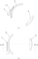
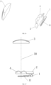
FIG. 1 is a three-dimensional schematic structural diagram 1 of an embodiment of the present invention; -
FIG. 2 is a three-dimensional schematic structural diagram 2 of an embodiment of the present invention; -
FIG. 3 is a top view ofFIG. 2 ; -
FIG. 4 is a section view along A-A ofFIG. 3 ; -
FIG. 5 is a side view ofFIG. 2 ; -
FIG. 6 is a section view along B-B ofFIG. 5 ; -
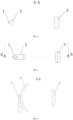
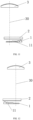
FIG. 7 is a schematic diagram of a light shape simulation of an embodiment of the present invention applied to a left headlight; -
FIG. 8 is a schematic diagram of a light shape line of an embodiment of the present invention applied to a left headlight; -
FIG. 9 is a schematic diagram of a light shape simulation of an embodiment of the present invention applied to a right headlight; -
FIG. 10 is a schematic diagram of a light shape line of an embodiment of the present invention applied to a right headlight; -
FIG. 11 is a top view of another embodiment of the present invention applied to a left headlight; -
FIG. 12 is a top view of another embodiment of the present invention applied to a right headlight; -
FIG. 13 is a top view of another embodiment of the present invention applied to a left headlight and a right headlight; -
FIG. 14 is a top view of another embodiment of the present invention, wherein an optical axis of a light-emitting source overlaps an optical axis of a corresponding light gathering unit; -
FIG. 15 is a top view of another embodiment of the present invention, wherein a light-emitting source located on the right side of an optical axis of a third-stage lens is arranged on the right side of an optical axis of a corresponding light gathering unit; -
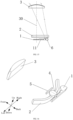
FIG. 16 is a three-dimensional schematic structural diagram 1 of still another embodiment of the present invention; -
FIG. 17 is a three-dimensional schematic structural diagram 2 of still another embodiment of the present invention; -
FIG. 18 is a top view ofFIG. 17 ; -
FIG. 19 is a section view along C-C ofFIG. 18 ; -
FIG. 20 is a three-dimensional schematic structural diagram 1 of a primary optical element in still another embodiment of the present invention; -
FIG. 21 is a three-dimensional schematic structural diagram 2 of a primary optical element in still another embodiment of the present invention; -
FIG. 22 is another three-dimensional schematic structural diagram 1 of a primary optical element in still another embodiment of the present invention; -
FIG. 23 is another three-dimensional schematic structural diagram 2 of a primary optical element in still another embodiment of the present invention; -
FIG. 24 is still another three-dimensional schematic structural diagram 1 of a primary optical element in still another embodiment of the present invention; -
FIG. 25 is still another three-dimensional schematic structural diagram 2 of a primary optical element in still another embodiment of the present invention; -
FIG. 26 is a three-dimensional schematic structural diagram of yet another embodiment of the present invention; and -
FIG. 27 is a top view of yet another embodiment of the present invention. -
1 first- stage lens 11 light gathering unit 2 second- stage lens 3 third- stage lens 30 optical axis of third- stage lens 4 primary optical element 41 primary light entry surface 42 primary light exit surface 43 light gathering cup structure 5 auxiliary cylindrical lens 6 light-emitting source - In the description of the present invention, it should be understood that orientations or positional relationships indicated by the terms "upper", "lower", "front", "rear", "left", "right" and the like are all orientations or positional relationships as shown in
FIG. 16 , and are only for the purpose of facilitating and simplifying the description of the present invention instead of indicating or implying that devices or elements indicated must have particular orientations, and be constructed and operated in the particular orientations, so that these terms are construed as limiting the present invention. - Specific embodiments of the present invention will be described in detail below with reference to the accompanying drawings. It should be understood that the specific embodiments described herein are only used to illustrate and explain the present invention, and are not intended to limit the present invention.
- As shown in
FIG. 1 to FIG. 27 , the present invention provides a vehicle high beam module, including a plurality of light-emittingsources 6 and a lens group. The lens group is arranged on an exit direction of light emitted by the light-emittingsources 6, and includes at least two stages of lenses; a first-stage lens 1 in the lens group includes a plurality oflight gathering units 11 that are arranged side by side and that have light entry surfaces of a set width; the light entry surfaces of the respectivelight gathering units 11 are in one-to-one correspondence with the light-emittingsources 6; light emitted by respective light-emittingsources 6 passes through the first-stage lens 1 and other lenses in the lens group in succession to then form a plurality of light shape forming units; the plurality of light shape forming units are arranged in succession in a high beam shape having a plurality of pixels; and a width of each light shape forming unit corresponds to the set width of the respective corresponding light entry surface, wherein the set width of each light entry surface is set so that the widths of the plurality of pixels decease from outer regions of a light shape to a central region of the light shape. - In the present invention, by means of the arrangement of the lens group including at least two stages of lenses, the plurality of light shape forming units can be formed, and are arranged in succession to form a continuous high beam shape. Meanwhile, light emitted by the light-emitting
sources 6 can be gathered as much as possible due to the gathering action of the multiple stages of lenses, so that the utilization rate of the light can be increased. Furthermore, the up-down size of the last stage lens can be made to be small, thus reducing the up-down size of the entire headlight module and achieving a small opening design of the vehicle headlight. The lens group preferably includes a first-stage lens 1, a second-stage lens 2 and a third-stage lens 3 which are arranged in succession along the exit direction of light emitted by the light-emittingsources 6; the first-stage lens 1 includes a plurality oflight gathering units 11. Eachlight gathering unit 11 can gather light emitted by the light-emittingsources 6 in up, down, left and right directions. Eachlight gathering unit 11 is preferably a plano-convex lens, that is, the light entry surface of eachlight gathering unit 11 is a plane, and a light exit surface of the light gathering lens is a forwards protruding curved surface. The variouslight gathering units 11 are connected into a whole. The second-stage lens 2 can gather light emitted by eachlight gathering unit 11 in the up-down direction, so that more light can enter the third-stage lens 3, and the up-down size of the third-stage lens 3 can be made to be small. The second-stage lens 2 is preferably a plano-convex cylindrical lens that extends in a left-right direction. A longitudinal cross-sectional line of a light entry surface of the second-stage lens 2 is a straight line. The longitudinal cross-sectional line of the light entry surface is a cross-sectional line of the light entry surface cut by a vertical plane that extends in a front-back direction. A longitudinal cross-sectional line of a light exit surface of the second-stage lens 2 is a forwards protruding curve. The longitudinal cross-sectional line of the light exit surface is a cross-sectional line of the light exit surface cut by the vertical plane that extends in the front-back direction. So that the second-stage lens 2 gathers light emitted by thelight gathering units 11 in the up-down direction, and more light can enter the third-stage lens 3. Of course, the second-stage lens 2 can also be a biconvex cylindrical lens. The third-stage lens 3 can be an ordinary lens, such as a plano-convex lens or a biconvex lens. - The first-
stage lens 1 of the present invention includes the plurality oflight gathering units 11 that are arranged side by side and have the light entry surfaces of the set width, so that light emitted by the respective light-emittingsources 6 passes through the first-stage lens 1 and other lenses in the lens group in succession to then form the plurality of light shape forming units, and the widths of the respective light shape forming units correspond to the set widths of the respective corresponding light entry surfaces, so that the high beam shape having a plurality of pixels with specific widths can be formed. The set widths of the respective light entry surfaces can be set so that the widths of the plurality of pixels decrease from the outer regions of the light shape to the central region of the light shape, thus achieving a high beam shape having a narrow pixel width (high resolution) in a region near a road right ahead of a vehicle and wide pixel width (low resolution) in regions on both sides of a road in front of the vehicle. - It should be noted that the high beam shape is formed by arranging the plurality of light shape forming units in succession along the left-right direction. If the respective light shape forming units are just connected, the widths of the pixels are the same as the widths of the corresponding light shape forming units. However, in this case, there will be obvious bright and dark boundary lines between the pixels, so that high beam shape has low uniformity. Therefore, in order to achieve uniform connection and transition between the pixels, the respective light shape forming units are partially superposed. At the moment, the widths of the light shape forming units shall be greater than the widths of the corresponding pixels. The widths of the respective light shape forming units correspond to the set widths of the respective corresponding light entry surfaces. Therefore, in order to achieve a light shape having a narrow pixel width in a region near a road right ahead of a vehicle and a wide pixel width in regions on both sides of a road in front of the vehicle, the set widths of the respective light entry surfaces can be set to obtain the light shape forming units with different widths, so as to form the high beam shape having a plurality of pixels with specific widths.
-
FIG. 7 and FIG. 9 are respectively schematic diagrams of light shape simulation of the above vehicle high beam module applied to a left headlight and a right headlight,FIG. 8 and FIG. 10 are respectively schematic diagrams of light shape lines of the above vehicle high beam module applied to a left headlight and a right headlight. Referring toFIG. 7 and FIG. 9 , the two light shapes are superposed to form the entire high beam shape of a vehicle. Regions on a light distribution screen projected by light irradiating the regions on both sides in front of the vehicle are outer regions of the light shape in the schematic diagrams of light shapes shown inFIG. 7 and FIG. 9 . The left region inFIG. 7 and the right region inFIG. 9 are the outer regions of the light shape. Regions on the light distribution screen projected by light irradiating near the region right ahead of the vehicle are the central region of the light shape in the schematic diagrams of the light shapes shown inFIG. 7 and FIG. 9 . The right region inFIG. 7 and the left region inFIG. 9 are the central region of the light shape. The scales in the figures represent the widths of all the pixels, which are represented by light irradiation angles. The widths of all the pixels inFIG. 7 decrease from left (the outer regions of the light shape) to right (the central region of the light shape). Correspondingly, when the headlight module of the present invention is applied to the left headlight, the set widths of the light entry surfaces of the respectivelight gathering units 11 are set from right to left to be in one-to-one correspondence with the widths of the respective pixels inFIG. 7 from left to right, that is, the set widths of the light entry surfaces of the plurality oflight gathering units 11 decrease from right to left. Specifically, as shown inFIG. 11 , thelight gathering units 11 of the left regions are close to an optical axis of third-stage lens 30, and the region on the light distribution screen projected by light emitted by thelight gathering units 11 of the left region is located in the central region of the light shape, so that the left region is referred to as the central region. Correspondingly, the right region is away from the optical axis of third-stage lens 30, and the region on the light distribution screen projected by light emitted by thelight gathering units 11 of the right region is located on the outer region of the light shape, so that the right region is referred to as the outer region. However, in order to achieve uniform connection between the pixels, the light shape forming units are partially superposed, and the set widths of the light entry surfaces of the plurality oflight gathering units 11 can be set according to the widths of the light shape forming units obtained according to needs, and do not necessarily have a gradual change trend, as long as the light shape forming units can be finally arranged to obtain a light shape with the pixel widths decreasing from the outer region of the light shape to the central region of the light shape. When the headlight module of the present invention is applied to the right headlight, the set widths of the light entry surfaces of the respectivelight gathering units 11 are set from left to right to be in one-to-one correspondence with the widths of the respective pixels inFIG. 9 from right to left, that is, the set widths of the light entry surfaces of the plurality oflight gathering units 11 decrease from left to right. Specifically, as shown inFIG. 12 , the respectivelight gathering units 11 of the right region are close to the optical axis of third-stage lens 30, similarly, the right region is referred to as the central region, the left region is away from the optical axis of third-stage lens 30, so that the left region is referred to as the outer region. However, in order to achieve uniform connection between the pixels, the light shape forming units are partially superposed, and the set widths of the light entry surfaces of the plurality oflight gathering units 11 can be set according to the widths of the light shape forming units obtained according to needs, and do not necessarily have a gradual change trend, as long as the light shape forming units can be finally arranged to obtain a light shape with the pixel widths decreasing from the outer region of the light shape to the central region of the light shape. Thus, when the vehicle high beam module of the present invention is applied to the left headlight and the right headlight, the set widths of the light entry surfaces of the plurality oflight gathering units 11 are set as follows: the light entry surfaces of thelight gathering units 11 of the outer regions are wider, and the light entry surfaces of thelight gathering units 11 of the central region are narrower. The set widths of the light entry surfaces of the plurality oflight gathering units 11 decrease from the outer regions to the central region, so that the high beam shape having narrower pixels in a region near straight ahead of a vehicle and wider pixels in regions on both sides in front of the vehicle can be formed after the high beam shapes formed by the left and right headlights are superposed. In addition, in order to make focal points of the plurality oflight gathering units 11 on the same straight line, the anteroposterior lengths of the plurality oflight gathering units 11 are set as follows: the anteroposterior lengths of thelight gathering units 11 of the outer regions are greater, and the anteroposterior lengths of thelight gathering units 11 of the central region are less. The anteroposterior lengths of the plurality oflight gathering units 11 decrease from the outer regions to the central region. That is, as shown inFIG. 11 , the anteroposterior lengths of the plurality oflight gathering units 11 decrease from right to left, and as shown inFIG. 12 , the anteroposterior lengths of the plurality oflight gathering units 11 decrease from left to right. - Preferably, in order to prevent mis-installation of the vehicle high beam module of the present invention on the left headlight and the right headlight, the headlight module of the present invention can adopt a structure that is applicable to the left headlight and the right headlight. That is, the first-
stage lenses 1 applied to the left headlight and the right headlight have the same structure. The set widths of the light entry surfaces of the plurality oflight gathering units 11 are set as follows: the light entry surfaces of thelight gathering units 11 of the outer regions are wide, and the light entry surfaces of thelight gathering units 11 of the central region are narrow. The set widths of the light entry surfaces of the plurality oflight gathering units 11 decrease from the outer regions to the central region. Specifically, as shown inFIG. 13 , the left and right regions of the plurality of thelight gathering units 11 are the outer regions, and the middle region is the central region. The set widths of the light entry surfaces of the plurality oflight gathering units 11 decrease from the left and right regions to the middle region, so that the high beam shape having the narrower pixel width in a region near straight ahead of a vehicle and the wide pixel width in regions on both sides in front of the vehicle can be formed after the high beam shapes formed by the left and right headlights are superposed. There are two implementations for the high beam shape of this structural form: in the first implementation, the light-emittingsources 6, corresponding to the right outer region and central region of the plurality oflight gathering units 11, of the vehicle high beam module in the left headlight are turned on, so that a light shape having a narrow pixel width in the central region of the light shape and a wide pixel width in the outer region of the light shape (the left region of the light shape) is formed by the left headlight. The light-emittingsources 6, corresponding to the left outer region and central region of the plurality oflight gathering units 11, of the vehicle high beam module in the right headlight are turned on, so that a light shape having a narrow pixel width in the central region of the light shape and a wide pixel with in the outer region of the light shape (the right region of the light shape) is formed by the right headlight. The two light shapes are superposed to form a complete high beam shape. Furthermore, the light-emittingsources 6, corresponding to the central regions of the plurality oflight gathering units 11, of the vehicle high beam modules in the left and right headlights are all turned on, so that the central regions of the high beam shapes formed by the superimposition of the left and right headlights are superposed, and the high beam shape has higher central brightness. In the second implementation, the light-emittingsources 6 of the vehicle high beam modules in the left and right headlights are all turned on, so that a light shape having a narrow pixel width in the central region of the light shape and a wide pixel width in the regions on both sides are formed by the left and right headlights, and a complete high beam shape can be formed after the two light shapes are superposed. Similarly, in order to make the focal points of the respectivelight gathering units 11 on the same straight line, the anteroposterior lengths of the plurality oflight gathering units 11 are set as follows: the anteroposterior lengths of the plurality oflight gathering units 11 of the outer regions (the left and right regions) are greater, and the anteroposterior lengths of thelight gathering units 11 of the central region (the middle region) are less. The anteroposterior lengths of the plurality oflight gathering units 11 decrease from the outer regions to the central region. - As shown in
FIG. 1 to FIG. 6 , the anteroposterior lengths of the respectivelight gathering units 11 are different, so that in order to match the second-stage lens with the respectivelight gathering units 11, the second-stage lens 2 has a certain curvature in the left-right direction. That is, the longitudinal cross-sectional line of the light entry surface of the second-stage lens 2 is a straight line or a backwards protruding curve, and the longitudinal cross-sectional line of the light exit surface of the second-stage lens is a forwards protruding curve, so that the second-stage lens 2 gathers, in the up-down direction, the light emitted by thelight gathering units 11, and more light can enter the third-stage lens 3. Furthermore, outer portions of the second-stage lens 2 corresponding to thelight gathering units 11 located in the outer regions are forwards bent, so that the light entry surface of the second-stage lens 2 can be close to the light exit surfaces of thelight gathering units 11 as much as possible, and more light emitted by thelight gathering units 11 enters the second-stage lens 2, thus increasing the utilization rate of light emitted by thelight gathering units 11. Meanwhile, the curvature of the second-stage lens 2 is close to the curvature of a focal plane of the third-stage lens 3, so that a clear light shape can be formed. It should be noted that the focal plane is theoretically a plane. However, due to the impact of an optical aberration, particularly a field curvature aberration, the focal plane of the third-stage lens 3 actually has a concave spherical curvature. Therefore, if the light exit surface of the second-stage lens 2 is arranged on the curved focal plane, a clearest image can be formed. Of course, the second-stage lens 2 may not have a curvature, either, and its light shape effect can also meet the requirement. In addition, preferably, the width of the second-stage lens 2 in the left-right direction is greater than the width of the first-stage lens 1 in the left-right direction, and the left and right sides of the second-stage lens are both forwards bent, so that the second-stage lens 2 can be applied to both the left headlight and the right headlight, which reduces the mold cost and improves the generality of parts. - Preferably, the respective light-emitting
sources 6 are all LED light sources, and are arranged on the focal points of the respective correspondinglight gathering units 11. - In order to further increase the utilization rate of light of the vehicle high beam module of the present invention, preferably, the light-emitting
source 6 located on the right side of the optical axis of third-stage lens 30 is arranged on the right side of the optical axis of the correspondinglight gathering unit 11, and the light-emittingsource 6 located on the left side of the optical axis of third-stage lens 30 is arranged on the left side of the optical axis of the correspondinglight gathering unit 11. Specifically, as shown inFIG. 15 , compared with the situation shown inFIG. 14 that the optical axis of the light-emittingsource 6 overlaps the optical axis of the correspondinglight gathering unit 11, more light emitted by the light-emittingsource 6 through thelight gathering unit 11 enters the third-stage lens 3, so that the utilization rate of light can be further increased. - The vehicle high beam module is a headlight module independent of a vehicle low beam module, and is different from a headlight module integrated with high beam and low beam. When the headlights are in a mode using low beam illumination modules, in front of a vehicle, the vehicle low beam module emits light, but the vehicle high beam module does not emit light. Therefore, in order to achieve an appearance effect that the vehicle high beam module also emits light in the low beam illumination mode, on the basis of the above embodiment, the vehicle high beam module can be additionally provided with a low beam auxiliary illumination unit which will not participate low beam illumination, and only plays a role of achieving an appearance effect that the third-
stage lens 3 is illuminated when the headlights are seen in front of the vehicle. The low beam auxiliary illumination unit can be arranged above or below or on the left side or on the right side of the second-stage lens 2. Preferably, the low beam auxiliary illumination unit is arranged above the second-stage lens 2, so that light emitted through the third-stage lens 3 can be projected into a light shape region of a low beam shape, without affecting low beam illumination, specifically as shown inFIG. 16 to FIG. 27 . - Specifically, the low beam auxiliary illumination unit includes a primary
optical element 4 and an auxiliary illumination light source (not shown in the figure) corresponding to the primaryoptical element 4; and light emitted by the auxiliary illumination light source enters the third-stage lens 3 after passing through the primaryoptical element 4, so that the third-stage lens 3 can be illuminated. - The primary
optical element 4 has an effect of gathering light emitted by the auxiliary illumination light source, and may has various structures. As one specific structure, as shown inFIG. 16 to FIG. 21 , the primaryoptical element 4 has a primarylight entry surface 41 and a primarylight exit surface 42; a light channel is formed in a front-back direction between the primarylight entry surface 41 and the primarylight exit surface 42; a lightgathering cup structure 43 is arranged on the primarylight entry surface 41; and an external contour surface of the lightgathering cup structure 43 is a curved surface with an aperture gradually increasing from back to front. More specifically, the primarylight entry surface 41 is a plane, and the primarylight exit surface 42 is a forwards protruding curved surface; an up-down height of the primarylight entry surface 41 is greater than an up-down height of the primarylight exit surface 42, so that more light enters the primarylight entry surface 41; and a left-right width of the primarylight entry surface 41 is less than a left-right width of the primarylight exit surface 42, which saves materials and reduces the production cost. The primaryoptical element 4 is provided with the lightgathering cup structure 43 on the primarylight entry surface 41, so that the light gathering effect is better, and the utilization rate of light is larger. - As still another specific structure, as shown in
FIG. 24 and FIG. 25 , the primaryoptical element 4 has a primarylight entry surface 41 and a primarylight exit surface 42; a light channel is formed in a front-back direction between the primarylight entry surface 41 and the primarylight exit surface 42; the primarylight entry surface 41 is a plane, and the primarylight exit surface 42 is a forwards protruding curved surface; an up-down height of the primarylight entry surface 41 is less than an up-down height of the primarylight exit surface 42; and a left-right width of the primarylight entry surface 41 is less than a left-right width of the primarylight exit surface 42. The primaryoptical element 4 has a simple structure, can save materials and reduce the production cost, and also has high utilization rate of light. - As yet another specific structure, as shown in
FIG. 22 and FIG. 23 , the primaryoptical element 4 has a primarylight entry surface 41 and a primarylight exit surface 42; a light channel is formed in a front-back direction between the primarylight entry surface 41 and the primarylight exit surface 42; the primarylight entry surface 41 is a plane, and the primarylight exit surface 42 is a forwards protruding curved surface; an up-down height of the primarylight entry surface 41 is equal to an up-down height of the primarylight exit surface 42; and a left-right width of the primarylight entry surface 41 is equal to a left-right width of the primarylight exit surface 42. The primaryoptical element 4 has a simpler structure and is easier to machine. - The anteroposterior size of the above various structures of the primary optical element is greatly different from the anteroposterior size of the second-stage lens, which is inconvenient for positioning and mounting the primary optical element, so that two or more primary
optical elements 4 can be arranged side by side along the left-right direction and are connected into a whole to reduce the size of the primaryoptical element 4 in the front-back direction. At the moment, the two or more primaryoptical elements 4 can be integrated with the second-stage lens 2, thus simplifying the structure of the headlight module, making the structure more compact, and facilitating the positioning and mounting of the primaryoptical element 4.FIG. 26 and FIG. 27 show that two primaryoptical elements 4 that are connected into a whole are integrated with the second-stage lens 2. - Preferably, as shown in
FIG. 16 to FIG. 19 , an auxiliarycylindrical lens 5 is arranged in front of the primaryoptical element 4, and is preferably a plano-convex cylindrical lens that extends in the left-right direction. The up-down size of the third-stage lens 3 is made to be small, so that by means of arranging the auxiliarycylindrical lens 5 in front of the primaryoptical element 4, light emitted by the primaryoptical element 4 can be gathered in the up-down direction, and more light can enter the third-stage lens 3, thus increasing the utilization rate of light of the low beam auxiliary illumination unit. Of course, the auxiliarycylindrical lens 5 may also be a biconvex cylindrical lens. - In a second aspect, the present invention further provides a vehicle headlight, including the vehicle high beam module.
- The vehicle high beam module which can achieve a small opening design for a light emitting port of a vehicle headlight and achieve a high beam shape having a narrow pixel width in a region near straight ahead of a vehicle and a wide pixel width in regions on both sides in front of the vehicle.
- In a third aspect, the present invention further provides a vehicle including the above vehicle headlight.
- By arranging the vehicle headlight, a high beam shape that has a narrow pixel width at the region near straight ahead of the vehicle and a wide pixel width in regions at two sides at the front of the vehicle are achieved.
- The preferable embodiments of the present invention are described above in detail with reference to the accompanying drawings. However, the present invention is not limited to the specific details in the foregoing implementation modes. Various simple variations can be made to the technical solutions of the present invention within the technical concept ranges of the present invention, and these simple variations all fall within the protection scope of the present invention.
- In addition, it should be noted that the various specific technical features described in the above specific embodiments can be combined in any suitable manner without contradiction. In order to avoid unnecessary repetition, various possible combination modes will not be additionally described in the present invention.
- In addition, various different embodiments of the present invention can also be arbitrarily combined, and these combinations should also be regarded as the content disclosed in the present invention, as long as they do not violate the idea of the present invention.
Claims (19)
- A vehicle high beam module, characterized by comprising a plurality of light-emitting sources (6) and a lens group, wherein the lens group is arranged on an exit direction of light emitted by the light-emitting sources (6), and comprises at least two stages of lenses; a first-stage lens (1) in the lens group comprises a plurality of light gathering units (11) that are arranged side by side and that have light entry surfaces of a set width; the light entry surfaces of the respective light gathering units (11) are in one-to-one correspondence with the light-emitting sources (6); light emitted by respective light-emitting sources (6) passes through the first-stage lens (1) and other lenses in the lens group in succession to then form a plurality of light shape forming units; the plurality of light shape forming units are arranged in succession in a high beam shape having a plurality of pixels; and a width of each light shape forming unit corresponds to the set width of the respective corresponding light entry surface, wherein the set width of each light entry surface is set so that the widths of the plurality of pixels decease from outer regions of the light shape to a central region of the light shape.
- The vehicle high beam module according to claim 1, characterized in that the set widths of the light entry surfaces of the plurality of light gathering units (11) are set to decrease from the outer regions to the central region.
- The vehicle high beam module according to claim 2, characterized in that anteroposterior lengths of the plurality of light gathering units (11) are set to decrease from the outer regions to the central region.
- The vehicle high beam module according to claim 1, characterized in that each light gathering unit (11) is a plano-convex lens; the light entry surface of each light gathering unit (11) is a plane; and a light exit surface of each light gathering unit is a forwards protruding curved surface; and the respective light gathering units (11) are connected into a whole.
- The vehicle high beam module according to any one of claims 1-4, characterized in that the lens group comprises the first-stage lens (1), a second-stage lens (2) and a third-stage lens (3) which are arranged in succession along the exit direction of light emitted by the light-emitting sources (6); and the second-stage lens (2) can gather light emitted by the first-stage lens (1) in an up-down direction.
- The vehicle high beam module according to claim 5, characterized in that the second-stage lens (2) is a plano-convex cylindrical lens that extends in a left-right direction, or a longitudinal cross-sectional line of a light entry surface of the second-stage lens (2) is a straight line, and a longitudinal cross-sectional line of a light exit surface of the second-stage lens is a forwards protruding curve; and an outer portion of the second-stage lens (2) bends forwards.
- The vehicle high beam module according to claim 5, characterized in that the third-stage lens (3) is a plano-convex lens or a biconvex lens.
- The vehicle high beam module according to claim 5, characterized in that the respective light-emitting sources (6) are all light-emitting diode (LED) light sources, and the respective light-emitting sources (6) are arranged on focal points of the respective corresponding light gathering units (11).
- The vehicle high beam module according to claim 5, characterized in that the light-emitting source (6) located on the right side of an optical axis of third-stage lens (30) is arranged on the right side of an optical axis of the corresponding light gathering unit (11); and the light-emitting source (6) located on the left side of the optical axis of third-stage lens (30) is arranged on the left side of the optical axis of the corresponding light gathering unit (11).
- The vehicle high beam module according to claim 5, characterized in that a low beam auxiliary illumination unit is arranged above or below or on the left side or the right side of the second-stage lens (2).
- The vehicle high beam module according to claim 10, characterized in that the low beam auxiliary illumination unit comprises a primary optical element (4) and an auxiliary illumination light source corresponding to the primary optical element (4); and light emitted by the auxiliary illumination light source enters the third-stage lens (3) after passing through the primary optical element (4), so that the third-stage lens (3) is illuminated.
- The vehicle high beam module according to claim 11, characterized in that an auxiliary cylindrical lens (5) is arranged in front of the primary optical element (4), and the auxiliary cylindrical lens (5) is a plano-convex cylindrical lens that extends in the left-right direction.
- The vehicle high beam module according to claim 11, characterized in that the primary optical element (4) has a primary light entry surface (41) and a primary light exit surface (42); a light channel is formed in a front-back direction between the primary light entry surface (41) and the primary light exit surface (42); a light gathering cup structure (43) is arranged on the primary light entry surface (41); and an external contour surface of the light gathering cup structure (43) is a curved surface with an aperture gradually increasing from back to front.
- The vehicle high beam module according to claim 13, characterized in that the primary light entry surface (41) is a plane, and the primary light exit surface (42) is a forwards protruding curved surface; an up-down height of the primary light entry surface (41) is greater than an up-down height of the primary light exit surface (42); and a left-right width of the primary light entry surface (41) is less than a left-right width of the primary light exit surface (42).
- The vehicle high beam module according to claim 11, characterized in that the primary optical element (4) has a primary light entry surface (41) and a primary light exit surface (42); a light channel is formed in a front-back direction between the primary light entry surface (41) and the primary light exit surface (42); the primary light entry surface (41) is a plane, and the primary light exit surface (42) is a forwards protruding curved surface; an up-down height of the primary light entry surface (41) is less than an up-down height of the primary light exit surface (42); and a left-right width of the primary light entry surface (41) is less than a left-right width of the primary light exit surface (42).
- The vehicle high beam module according to claim 11, characterized in that the primary optical element (4) has a primary light entry surface (41) and a primary light exit surface (42); a light channel is formed in a front-back direction between the primary light entry surface (41) and the primary light exit surface (42); the primary light entry surface (41) is a plane, and the primary light exit surface (42) is a forwards protruding curved surface; an up-down height of the primary light entry surface (41) is equal to an up-down height of the primary light exit surface (42); and a left-right width of the primary light entry surface (41) is equal to a left-right width of the primary light exit surface (42).
- The vehicle high beam module according to claim 10, characterized in that a low beam auxiliary illumination unit is arranged above the second-stage lens (2); the low beam auxiliary illumination unit comprises two or more primary optical elements (4) that are arranged side by side along the left-right direction and are connected into a whole, and auxiliary illumination light sources that are in one-to-one correspondence with the primary optical elements (4); each primary optical element (4) has a primary light entry surface (41) and a primary light exit surface (42); a light channel is formed in a front-back direction between the primary light entry surface (41) and the primary light exit surface (42); and the two or more primary optical elements (4) are integrated with the second-stage lens (2).
- A vehicle headlight, characterized by comprising the vehicle high beam module according to any one of claims 1-17.
- A vehicle, characterized by comprising the vehicle headlight according to claim 18.
Applications Claiming Priority (2)
| Application Number | Priority Date | Filing Date | Title |
|---|---|---|---|
| CN202010690413.2A CN112781002A (en) | 2020-07-17 | 2020-07-17 | Vehicle high beam module, vehicle headlamp and vehicle |
| PCT/CN2021/106540 WO2022012634A1 (en) | 2020-07-17 | 2021-07-15 | Vehicle high beam module, vehicle headlight, and vehicle |
Publications (2)
| Publication Number | Publication Date |
|---|---|
| EP4170230A1 true EP4170230A1 (en) | 2023-04-26 |
| EP4170230A4 EP4170230A4 (en) | 2024-01-10 |
Family
ID=75750123
Family Applications (1)
| Application Number | Title | Priority Date | Filing Date |
|---|---|---|---|
| EP21842895.1A Pending EP4170230A4 (en) | 2020-07-17 | 2021-07-15 | Vehicle high beam module, vehicle headlight, and vehicle |
Country Status (3)
| Country | Link |
|---|---|
| EP (1) | EP4170230A4 (en) |
| CN (1) | CN112781002A (en) |
| WO (1) | WO2022012634A1 (en) |
Families Citing this family (1)
| Publication number | Priority date | Publication date | Assignee | Title |
|---|---|---|---|---|
| CN112781002A (en) * | 2020-07-17 | 2021-05-11 | 华域视觉科技(上海)有限公司 | Vehicle high beam module, vehicle headlamp and vehicle |
Family Cites Families (13)
| Publication number | Priority date | Publication date | Assignee | Title |
|---|---|---|---|---|
| FR2999679B1 (en) * | 2012-12-14 | 2015-01-16 | Valeo Vision | PRIMARY OPTICAL ELEMENT, LIGHTING MODULE AND PROJECTOR FOR MOTOR VEHICLE. |
| KR20170062851A (en) * | 2015-11-30 | 2017-06-08 | 에스엘 주식회사 | Lamp for vehicle |
| CN207527498U (en) | 2017-09-14 | 2018-06-22 | 上海小糸车灯有限公司 | A kind of collimation lens and its automobile-used optics module |
| CN107664295B (en) * | 2017-09-14 | 2024-02-02 | 华域视觉科技(上海)有限公司 | Collimating lens and vehicle optical module thereof |
| KR102014874B1 (en) * | 2018-02-27 | 2019-08-27 | 에스엘 주식회사 | Lamp for vehicle |
| CN207962511U (en) | 2018-04-13 | 2018-10-12 | 华域视觉科技(上海)有限公司 | Optics module and car light |
| FR3085463B1 (en) * | 2018-08-31 | 2022-03-25 | Valeo Vision | MOTOR VEHICLE LIGHT MODULE COMPRISING A PLURALITY OF LIGHT GUIDES |
| US11365858B2 (en) * | 2018-10-25 | 2022-06-21 | Hasco Vision Technology Co., Ltd. | Lighting module, vehicle lamp and vehicle |
| CN209165280U (en) * | 2019-01-10 | 2019-07-26 | 台州保镖电子有限公司 | A kind of LED light assembly of electric vehicle or the automobile-used multiple light courcess poly-lens of motor |
| CN111503590A (en) * | 2019-06-05 | 2020-08-07 | 华域视觉科技(上海)有限公司 | Car light optical element, car light module, vehicle headlamp and vehicle |
| CN210771911U (en) * | 2019-10-31 | 2020-06-16 | 浙江天合车灯有限公司 | Far and near light side emitting device of LED automobile headlamp assembly |
| CN112781002A (en) * | 2020-07-17 | 2021-05-11 | 华域视觉科技(上海)有限公司 | Vehicle high beam module, vehicle headlamp and vehicle |
| CN212987096U (en) * | 2020-07-17 | 2021-04-16 | 华域视觉科技(上海)有限公司 | Vehicle high beam module, vehicle headlamp and vehicle |
-
2020
- 2020-07-17 CN CN202010690413.2A patent/CN112781002A/en active Pending
-
2021
- 2021-07-15 EP EP21842895.1A patent/EP4170230A4/en active Pending
- 2021-07-15 WO PCT/CN2021/106540 patent/WO2022012634A1/en unknown
Also Published As
| Publication number | Publication date |
|---|---|
| EP4170230A4 (en) | 2024-01-10 |
| WO2022012634A1 (en) | 2022-01-20 |
| CN112781002A (en) | 2021-05-11 |
Similar Documents
| Publication | Publication Date | Title |
|---|---|---|
| AT518552B1 (en) | Lighting unit for a motor vehicle headlight for generating at least two light distributions | |
| EP2754948B1 (en) | Light module for a motor vehicle headlamp, which is equipped for forming strip-shaped light distributions | |
| US7686489B2 (en) | Light source device and vehicle lighting device | |
| US10337684B2 (en) | Lighting device for a motor vehicle comprising a light guide | |
| KR102611832B1 (en) | Vehicle lamp lighting modules, vehicle lamps and vehicles | |
| JP2019153577A (en) | Light module comprising primary optical element equipped with two forming layers | |
| US10913387B2 (en) | Lighting device projecting two vertically offset matrices of light pixels | |
| EP4170230A1 (en) | Vehicle high beam module, vehicle headlight, and vehicle | |
| CN109681838A (en) | A kind of the primary optical unit and car light of optics module | |
| CN113958921A (en) | Lighting module, lighting device and vehicle | |
| US11306891B1 (en) | Vehicle light optical element, vehicle light module, vehicle headlight and vehicle | |
| WO2020233573A1 (en) | Matrix-type vehicle lamp optical apparatus, vehicle lamp, and vehicle | |
| CN210373267U (en) | Car light module, car light and vehicle | |
| CN212987096U (en) | Vehicle high beam module, vehicle headlamp and vehicle | |
| US20210381667A1 (en) | Illumination module, vehicle lamp, and vehicle | |
| EP4130556A1 (en) | Vehicle lamp optical assembly, vehicle lamp module, vehicle lamp, and vehicle | |
| EP4130853A1 (en) | Lens unit, optical lens, illumination module, vehicle light, and vehicle | |
| EP3988836B1 (en) | Optical element, vehicle lamp module, vehicle lamp, and vehicle | |
| WO2022068267A1 (en) | Adb high beam module and vehicle lamp | |
| CN212746311U (en) | ADB high beam module and car light | |
| WO2022134456A1 (en) | Adb vehicle light module, vehicle light and vehicle | |
| WO2022099956A1 (en) | Vehicle headlamp system and vehicle lamp | |
| CN209245962U (en) | A kind of the primary optical unit and car light of optics module | |
| CN210568143U (en) | Headlamp lighting module and vehicle | |
| CN220817516U (en) | Car lamp lens, car lamp module and vehicle |
Legal Events
| Date | Code | Title | Description |
|---|---|---|---|
| STAA | Information on the status of an ep patent application or granted ep patent |
Free format text: STATUS: THE INTERNATIONAL PUBLICATION HAS BEEN MADE |
|
| PUAI | Public reference made under article 153(3) epc to a published international application that has entered the european phase |
Free format text: ORIGINAL CODE: 0009012 |
|
| STAA | Information on the status of an ep patent application or granted ep patent |
Free format text: STATUS: REQUEST FOR EXAMINATION WAS MADE |
|
| 17P | Request for examination filed |
Effective date: 20230120 |
|
| AK | Designated contracting states |
Kind code of ref document: A1 Designated state(s): AL AT BE BG CH CY CZ DE DK EE ES FI FR GB GR HR HU IE IS IT LI LT LU LV MC MK MT NL NO PL PT RO RS SE SI SK SM TR |
|
| DAV | Request for validation of the european patent (deleted) | ||
| DAX | Request for extension of the european patent (deleted) | ||
| A4 | Supplementary search report drawn up and despatched |
Effective date: 20231212 |
|
| RIC1 | Information provided on ipc code assigned before grant |
Ipc: F21Y 115/10 20160101ALI20231206BHEP Ipc: F21W 107/10 20180101ALI20231206BHEP Ipc: F21W 102/13 20180101ALI20231206BHEP Ipc: F21S 41/26 20180101ALI20231206BHEP Ipc: F21S 41/20 20180101ALI20231206BHEP Ipc: F21S 41/143 20180101ALI20231206BHEP Ipc: F21S 41/141 20180101AFI20231206BHEP |