EP4170224A1 - Plant for treating gas, particularly natural gas, supplied by a transmission network - Google Patents
Plant for treating gas, particularly natural gas, supplied by a transmission network Download PDFInfo
- Publication number
- EP4170224A1 EP4170224A1 EP22198533.6A EP22198533A EP4170224A1 EP 4170224 A1 EP4170224 A1 EP 4170224A1 EP 22198533 A EP22198533 A EP 22198533A EP 4170224 A1 EP4170224 A1 EP 4170224A1
- Authority
- EP
- European Patent Office
- Prior art keywords
- plant
- gas
- heat exchanger
- plant portion
- segment
- Prior art date
- Legal status (The legal status is an assumption and is not a legal conclusion. Google has not performed a legal analysis and makes no representation as to the accuracy of the status listed.)
- Granted
Links
Images

Classifications
-
- F—MECHANICAL ENGINEERING; LIGHTING; HEATING; WEAPONS; BLASTING
- F25—REFRIGERATION OR COOLING; COMBINED HEATING AND REFRIGERATION SYSTEMS; HEAT PUMP SYSTEMS; MANUFACTURE OR STORAGE OF ICE; LIQUEFACTION SOLIDIFICATION OF GASES
- F25J—LIQUEFACTION, SOLIDIFICATION OR SEPARATION OF GASES OR GASEOUS OR LIQUEFIED GASEOUS MIXTURES BY PRESSURE AND COLD TREATMENT OR BY BRINGING THEM INTO THE SUPERCRITICAL STATE
- F25J1/00—Processes or apparatus for liquefying or solidifying gases or gaseous mixtures
- F25J1/02—Processes or apparatus for liquefying or solidifying gases or gaseous mixtures requiring the use of refrigeration, e.g. of helium or hydrogen ; Details and kind of the refrigeration system used; Integration with other units or processes; Controlling aspects of the process
- F25J1/0228—Coupling of the liquefaction unit to other units or processes, so-called integrated processes
- F25J1/0232—Coupling of the liquefaction unit to other units or processes, so-called integrated processes integration within a pressure letdown station of a high pressure pipeline system
-
- F—MECHANICAL ENGINEERING; LIGHTING; HEATING; WEAPONS; BLASTING
- F17—STORING OR DISTRIBUTING GASES OR LIQUIDS
- F17D—PIPE-LINE SYSTEMS; PIPE-LINES
- F17D1/00—Pipe-line systems
- F17D1/02—Pipe-line systems for gases or vapours
- F17D1/04—Pipe-line systems for gases or vapours for distribution of gas
-
- F—MECHANICAL ENGINEERING; LIGHTING; HEATING; WEAPONS; BLASTING
- F25—REFRIGERATION OR COOLING; COMBINED HEATING AND REFRIGERATION SYSTEMS; HEAT PUMP SYSTEMS; MANUFACTURE OR STORAGE OF ICE; LIQUEFACTION SOLIDIFICATION OF GASES
- F25J—LIQUEFACTION, SOLIDIFICATION OR SEPARATION OF GASES OR GASEOUS OR LIQUEFIED GASEOUS MIXTURES BY PRESSURE AND COLD TREATMENT OR BY BRINGING THEM INTO THE SUPERCRITICAL STATE
- F25J1/00—Processes or apparatus for liquefying or solidifying gases or gaseous mixtures
- F25J1/0002—Processes or apparatus for liquefying or solidifying gases or gaseous mixtures characterised by the fluid to be liquefied
- F25J1/0022—Hydrocarbons, e.g. natural gas
-
- F—MECHANICAL ENGINEERING; LIGHTING; HEATING; WEAPONS; BLASTING
- F25—REFRIGERATION OR COOLING; COMBINED HEATING AND REFRIGERATION SYSTEMS; HEAT PUMP SYSTEMS; MANUFACTURE OR STORAGE OF ICE; LIQUEFACTION SOLIDIFICATION OF GASES
- F25J—LIQUEFACTION, SOLIDIFICATION OR SEPARATION OF GASES OR GASEOUS OR LIQUEFIED GASEOUS MIXTURES BY PRESSURE AND COLD TREATMENT OR BY BRINGING THEM INTO THE SUPERCRITICAL STATE
- F25J1/00—Processes or apparatus for liquefying or solidifying gases or gaseous mixtures
- F25J1/003—Processes or apparatus for liquefying or solidifying gases or gaseous mixtures characterised by the kind of cold generation within the liquefaction unit for compensating heat leaks and liquid production
- F25J1/0032—Processes or apparatus for liquefying or solidifying gases or gaseous mixtures characterised by the kind of cold generation within the liquefaction unit for compensating heat leaks and liquid production using the feed stream itself or separated fractions from it, i.e. "internal refrigeration"
- F25J1/004—Processes or apparatus for liquefying or solidifying gases or gaseous mixtures characterised by the kind of cold generation within the liquefaction unit for compensating heat leaks and liquid production using the feed stream itself or separated fractions from it, i.e. "internal refrigeration" by flash gas recovery
-
- F—MECHANICAL ENGINEERING; LIGHTING; HEATING; WEAPONS; BLASTING
- F25—REFRIGERATION OR COOLING; COMBINED HEATING AND REFRIGERATION SYSTEMS; HEAT PUMP SYSTEMS; MANUFACTURE OR STORAGE OF ICE; LIQUEFACTION SOLIDIFICATION OF GASES
- F25J—LIQUEFACTION, SOLIDIFICATION OR SEPARATION OF GASES OR GASEOUS OR LIQUEFIED GASEOUS MIXTURES BY PRESSURE AND COLD TREATMENT OR BY BRINGING THEM INTO THE SUPERCRITICAL STATE
- F25J1/00—Processes or apparatus for liquefying or solidifying gases or gaseous mixtures
- F25J1/003—Processes or apparatus for liquefying or solidifying gases or gaseous mixtures characterised by the kind of cold generation within the liquefaction unit for compensating heat leaks and liquid production
- F25J1/0032—Processes or apparatus for liquefying or solidifying gases or gaseous mixtures characterised by the kind of cold generation within the liquefaction unit for compensating heat leaks and liquid production using the feed stream itself or separated fractions from it, i.e. "internal refrigeration"
- F25J1/0045—Processes or apparatus for liquefying or solidifying gases or gaseous mixtures characterised by the kind of cold generation within the liquefaction unit for compensating heat leaks and liquid production using the feed stream itself or separated fractions from it, i.e. "internal refrigeration" by vaporising a liquid return stream
-
- F—MECHANICAL ENGINEERING; LIGHTING; HEATING; WEAPONS; BLASTING
- F25—REFRIGERATION OR COOLING; COMBINED HEATING AND REFRIGERATION SYSTEMS; HEAT PUMP SYSTEMS; MANUFACTURE OR STORAGE OF ICE; LIQUEFACTION SOLIDIFICATION OF GASES
- F25J—LIQUEFACTION, SOLIDIFICATION OR SEPARATION OF GASES OR GASEOUS OR LIQUEFIED GASEOUS MIXTURES BY PRESSURE AND COLD TREATMENT OR BY BRINGING THEM INTO THE SUPERCRITICAL STATE
- F25J1/00—Processes or apparatus for liquefying or solidifying gases or gaseous mixtures
- F25J1/006—Processes or apparatus for liquefying or solidifying gases or gaseous mixtures characterised by the refrigerant fluid used
- F25J1/008—Hydrocarbons
- F25J1/0082—Methane
-
- F—MECHANICAL ENGINEERING; LIGHTING; HEATING; WEAPONS; BLASTING
- F25—REFRIGERATION OR COOLING; COMBINED HEATING AND REFRIGERATION SYSTEMS; HEAT PUMP SYSTEMS; MANUFACTURE OR STORAGE OF ICE; LIQUEFACTION SOLIDIFICATION OF GASES
- F25J—LIQUEFACTION, SOLIDIFICATION OR SEPARATION OF GASES OR GASEOUS OR LIQUEFIED GASEOUS MIXTURES BY PRESSURE AND COLD TREATMENT OR BY BRINGING THEM INTO THE SUPERCRITICAL STATE
- F25J1/00—Processes or apparatus for liquefying or solidifying gases or gaseous mixtures
- F25J1/02—Processes or apparatus for liquefying or solidifying gases or gaseous mixtures requiring the use of refrigeration, e.g. of helium or hydrogen ; Details and kind of the refrigeration system used; Integration with other units or processes; Controlling aspects of the process
- F25J1/0201—Processes or apparatus for liquefying or solidifying gases or gaseous mixtures requiring the use of refrigeration, e.g. of helium or hydrogen ; Details and kind of the refrigeration system used; Integration with other units or processes; Controlling aspects of the process using only internal refrigeration means, i.e. without external refrigeration
-
- F—MECHANICAL ENGINEERING; LIGHTING; HEATING; WEAPONS; BLASTING
- F17—STORING OR DISTRIBUTING GASES OR LIQUIDS
- F17C—VESSELS FOR CONTAINING OR STORING COMPRESSED, LIQUEFIED OR SOLIDIFIED GASES; FIXED-CAPACITY GAS-HOLDERS; FILLING VESSELS WITH, OR DISCHARGING FROM VESSELS, COMPRESSED, LIQUEFIED, OR SOLIDIFIED GASES
- F17C2223/00—Handled fluid before transfer, i.e. state of fluid when stored in the vessel or before transfer from the vessel
- F17C2223/01—Handled fluid before transfer, i.e. state of fluid when stored in the vessel or before transfer from the vessel characterised by the phase
- F17C2223/0107—Single phase
- F17C2223/0123—Single phase gaseous, e.g. CNG, GNC
-
- F—MECHANICAL ENGINEERING; LIGHTING; HEATING; WEAPONS; BLASTING
- F17—STORING OR DISTRIBUTING GASES OR LIQUIDS
- F17C—VESSELS FOR CONTAINING OR STORING COMPRESSED, LIQUEFIED OR SOLIDIFIED GASES; FIXED-CAPACITY GAS-HOLDERS; FILLING VESSELS WITH, OR DISCHARGING FROM VESSELS, COMPRESSED, LIQUEFIED, OR SOLIDIFIED GASES
- F17C2223/00—Handled fluid before transfer, i.e. state of fluid when stored in the vessel or before transfer from the vessel
- F17C2223/03—Handled fluid before transfer, i.e. state of fluid when stored in the vessel or before transfer from the vessel characterised by the pressure level
- F17C2223/035—High pressure (>10 bar)
-
- F—MECHANICAL ENGINEERING; LIGHTING; HEATING; WEAPONS; BLASTING
- F17—STORING OR DISTRIBUTING GASES OR LIQUIDS
- F17C—VESSELS FOR CONTAINING OR STORING COMPRESSED, LIQUEFIED OR SOLIDIFIED GASES; FIXED-CAPACITY GAS-HOLDERS; FILLING VESSELS WITH, OR DISCHARGING FROM VESSELS, COMPRESSED, LIQUEFIED, OR SOLIDIFIED GASES
- F17C2225/00—Handled fluid after transfer, i.e. state of fluid after transfer from the vessel
- F17C2225/01—Handled fluid after transfer, i.e. state of fluid after transfer from the vessel characterised by the phase
- F17C2225/0107—Single phase
- F17C2225/0123—Single phase gaseous, e.g. CNG, GNC
-
- F—MECHANICAL ENGINEERING; LIGHTING; HEATING; WEAPONS; BLASTING
- F17—STORING OR DISTRIBUTING GASES OR LIQUIDS
- F17C—VESSELS FOR CONTAINING OR STORING COMPRESSED, LIQUEFIED OR SOLIDIFIED GASES; FIXED-CAPACITY GAS-HOLDERS; FILLING VESSELS WITH, OR DISCHARGING FROM VESSELS, COMPRESSED, LIQUEFIED, OR SOLIDIFIED GASES
- F17C2225/00—Handled fluid after transfer, i.e. state of fluid after transfer from the vessel
- F17C2225/01—Handled fluid after transfer, i.e. state of fluid after transfer from the vessel characterised by the phase
- F17C2225/0146—Two-phase
- F17C2225/0153—Liquefied gas, e.g. LPG, GPL
-
- F—MECHANICAL ENGINEERING; LIGHTING; HEATING; WEAPONS; BLASTING
- F17—STORING OR DISTRIBUTING GASES OR LIQUIDS
- F17C—VESSELS FOR CONTAINING OR STORING COMPRESSED, LIQUEFIED OR SOLIDIFIED GASES; FIXED-CAPACITY GAS-HOLDERS; FILLING VESSELS WITH, OR DISCHARGING FROM VESSELS, COMPRESSED, LIQUEFIED, OR SOLIDIFIED GASES
- F17C2225/00—Handled fluid after transfer, i.e. state of fluid after transfer from the vessel
- F17C2225/03—Handled fluid after transfer, i.e. state of fluid after transfer from the vessel characterised by the pressure level
- F17C2225/033—Small pressure, e.g. for liquefied gas
-
- F—MECHANICAL ENGINEERING; LIGHTING; HEATING; WEAPONS; BLASTING
- F17—STORING OR DISTRIBUTING GASES OR LIQUIDS
- F17C—VESSELS FOR CONTAINING OR STORING COMPRESSED, LIQUEFIED OR SOLIDIFIED GASES; FIXED-CAPACITY GAS-HOLDERS; FILLING VESSELS WITH, OR DISCHARGING FROM VESSELS, COMPRESSED, LIQUEFIED, OR SOLIDIFIED GASES
- F17C2227/00—Transfer of fluids, i.e. method or means for transferring the fluid; Heat exchange with the fluid
- F17C2227/03—Heat exchange with the fluid
- F17C2227/0337—Heat exchange with the fluid by cooling
- F17C2227/0339—Heat exchange with the fluid by cooling using the same fluid
-
- F—MECHANICAL ENGINEERING; LIGHTING; HEATING; WEAPONS; BLASTING
- F17—STORING OR DISTRIBUTING GASES OR LIQUIDS
- F17C—VESSELS FOR CONTAINING OR STORING COMPRESSED, LIQUEFIED OR SOLIDIFIED GASES; FIXED-CAPACITY GAS-HOLDERS; FILLING VESSELS WITH, OR DISCHARGING FROM VESSELS, COMPRESSED, LIQUEFIED, OR SOLIDIFIED GASES
- F17C2227/00—Transfer of fluids, i.e. method or means for transferring the fluid; Heat exchange with the fluid
- F17C2227/03—Heat exchange with the fluid
- F17C2227/0337—Heat exchange with the fluid by cooling
- F17C2227/0358—Heat exchange with the fluid by cooling by expansion
- F17C2227/036—"Joule-Thompson" effect
-
- F—MECHANICAL ENGINEERING; LIGHTING; HEATING; WEAPONS; BLASTING
- F25—REFRIGERATION OR COOLING; COMBINED HEATING AND REFRIGERATION SYSTEMS; HEAT PUMP SYSTEMS; MANUFACTURE OR STORAGE OF ICE; LIQUEFACTION SOLIDIFICATION OF GASES
- F25J—LIQUEFACTION, SOLIDIFICATION OR SEPARATION OF GASES OR GASEOUS OR LIQUEFIED GASEOUS MIXTURES BY PRESSURE AND COLD TREATMENT OR BY BRINGING THEM INTO THE SUPERCRITICAL STATE
- F25J2210/00—Processes characterised by the type or other details of the feed stream
- F25J2210/06—Splitting of the feed stream, e.g. for treating or cooling in different ways
-
- F—MECHANICAL ENGINEERING; LIGHTING; HEATING; WEAPONS; BLASTING
- F25—REFRIGERATION OR COOLING; COMBINED HEATING AND REFRIGERATION SYSTEMS; HEAT PUMP SYSTEMS; MANUFACTURE OR STORAGE OF ICE; LIQUEFACTION SOLIDIFICATION OF GASES
- F25J—LIQUEFACTION, SOLIDIFICATION OR SEPARATION OF GASES OR GASEOUS OR LIQUEFIED GASEOUS MIXTURES BY PRESSURE AND COLD TREATMENT OR BY BRINGING THEM INTO THE SUPERCRITICAL STATE
- F25J2230/00—Processes or apparatus involving steps for increasing the pressure of gaseous process streams
- F25J2230/30—Compression of the feed stream
-
- F—MECHANICAL ENGINEERING; LIGHTING; HEATING; WEAPONS; BLASTING
- F25—REFRIGERATION OR COOLING; COMBINED HEATING AND REFRIGERATION SYSTEMS; HEAT PUMP SYSTEMS; MANUFACTURE OR STORAGE OF ICE; LIQUEFACTION SOLIDIFICATION OF GASES
- F25J—LIQUEFACTION, SOLIDIFICATION OR SEPARATION OF GASES OR GASEOUS OR LIQUEFIED GASEOUS MIXTURES BY PRESSURE AND COLD TREATMENT OR BY BRINGING THEM INTO THE SUPERCRITICAL STATE
- F25J2240/00—Processes or apparatus involving steps for expanding of process streams
- F25J2240/40—Expansion without extracting work, i.e. isenthalpic throttling, e.g. JT valve, regulating valve or venturi, or isentropic nozzle, e.g. Laval
-
- F—MECHANICAL ENGINEERING; LIGHTING; HEATING; WEAPONS; BLASTING
- F25—REFRIGERATION OR COOLING; COMBINED HEATING AND REFRIGERATION SYSTEMS; HEAT PUMP SYSTEMS; MANUFACTURE OR STORAGE OF ICE; LIQUEFACTION SOLIDIFICATION OF GASES
- F25J—LIQUEFACTION, SOLIDIFICATION OR SEPARATION OF GASES OR GASEOUS OR LIQUEFIED GASEOUS MIXTURES BY PRESSURE AND COLD TREATMENT OR BY BRINGING THEM INTO THE SUPERCRITICAL STATE
- F25J2290/00—Other details not covered by groups F25J2200/00 - F25J2280/00
- F25J2290/34—Details about subcooling of liquids
Definitions
- the present invention refers to a plant for treating gas, particularly for treating natural gas (typically substantially consisting of methane) supplied by a transmission network, such as a gas pipeline or a methane pipeline, which must be processed before supplying it to the end-users in a gas or liquefied state.
- a transmission network such as a gas pipeline or a methane pipeline
- MRS Metering and Regulating Stations
- the gas is subjected to a measuring step (by suitable measuring apparatuses) and to a regulation step, in other words its pressure is reduced by a process reducing the gas pressure in the transmission network to a predefined lower pressure, for the distribution network.
- the gas is further subjected to additional treatments, particularly to a filtration step, a step preheating the gas to a predefined temperature, and to an odorizing step.
- the preheating step is performed because the pressure drop (typically from 60 bar to 5 bar) cools down the gas and such cooling, if not prevented, can freeze the pipes and also the metering and regulating apparatuses, which in turn determines a supply disruption.
- the preheating step is performed by burning a gas fraction in a water heating boiler, which in turn is used for preheating the gas. Therefore, the preheating step is an additional expense and also an energy waste.
- a further alternative approach of delivering natural gas consists of delivering LNG (liquefied natural gas).
- LNG liquefied natural gas
- the extracted natural gas is subjected to a liquefying step by consecutive cooling and condensing steps, then it is transported inside tanks typically by land or sea.
- the liquefied natural gas can then be subjected to regasification before being introduced into the distribution network, or can be used in the liquid state, for example, in the automotive and/or industrial field.
- the known liquefying plants for example the Linde cycle plant or the likes generally compress the gas, cool it down, and then they decompress it, by exploiting this further pressure drop for ultimately cooling down the gas in order to liquefy it.
- the compression required to enable the liquefying process is also one of the main costs with reference to the power consumption.
- this liquefying plants there is always a waste gas component which is difficult to manage.
- an object of the present invention consists of making available a plant for treating gas, particularly natural gas, supplied by a transmission network, for supplying, on one side, liquefied gas at a lower pressure, destined for example to the distribution network, and from another side, liquefied gas destined to be used in the automotive and/or industrial fields, enabling to reduce the energy wastes associated to the respective processes according to the beforehand prior art.
- a plant for treating gas particularly natural gas (typically comprising methane) is generally indicated by reference 1.
- the plant 1 receives at the inlet gas supplied by a transmission network (not shown in the figures) and, to this purpose, it comprises an inlet 2 connectable to said transmission network.
- the natural gas conveyed by the transmission network which enters the plant 1 is at a high pressure, typically between 35 and 75 bar.
- the plant 1 comprises a first plant portion 100 for decompressing a first fraction of the gas supplied by the transmission network and a first outlet 101 for supplying the decompressed gas at an outlet predefined pressure from the plant 1 itself, particularly to a distribution network (not shown in the figures), which the first outlet 101 is connectable to.
- the decompressed gas delivered at the first outlet 101 is typically at a pressure of about 5 bar for methane gas, therefore at a pressure lower than the pressure of the transmission network.
- the gas is supplied at the outlet at an outlet predefined temperature, which can be comprised between 5°C and 50°C, for example, generally greater than the temperature of the gas in the transmission network.
- the plant 1 comprises a second plant portion 200 for liquefying a second fraction of the gas supplied by the transmission network and a second outlet 201 for supplying the liquefied gas, typically LNG, flowing out the plant 1 itself, where the liquefied gas can be stored in tanks in order to be transported away.
- the liquefied gas supplied at the second outlet 201 is typically at a temperature of about -150°C and at a pressure comprised between about 4 and 5 bar in case of LNG.
- the plant 1 comprises a flow divider 3 for separating the gas entering through the inlet 2 into the first fraction destined to the first plant portion 100 and into the second fraction destined to the second plant portion 200.
- the flow divider 3 is configured so that all the entering gas is delivered to the first 100 and second plant portions 200.
- the first gas fraction is greater than the second gas fraction, in order to meet the working flow rate and the requirements of the distribution network.
- the first plant portion 100 comprises a throttle valve 102 in which the first gas fraction from the flow divider 3 is subjected to a temperature and pressure reductions by generally remaining in the gas state.
- the first plant portion 100 comprises a first heat exchanger 103 establishing a thermal exchange relationship between the segment of the first plant portion 100 placed downstream the throttle valve 102 and the second plant portion 200, wherein the first gas fraction is heated by the second gas fraction flowing in the second plant portion 200, which cools down accordingly.
- the first plant portion 100 comprises a second heat exchanger 104 establishing a thermal exchange relationship between the segment of the first portion 100 placed downstream the first heat exchanger 103 and the segment of the first plant portion 100 placed upstream the throttle valve 102.
- the gas in the first plant portion 100 supplied by the flow divider 3 is precooled by the cooler gas coming from the throttle valve 102 and by the first heat exchanger 103, which in turn is heated.
- Such gas from the second heat exchanger 104 can be supplied to the first outlet 101 and delivered therefrom to the distribution network.
- the second plant portion 200 comprises, as beforehand cited, a first heat exchanger 103, in which the second gas fraction from the flow divider 3 is cooled down and at least partially liquefied.
- the second plant portion 200 downstream the first exchanger 103, comprises a throttle valve 202 determining a further temperature and pressure reductions of the liquefied gas.
- the liquefied gas from the throttle valve 202 therefore can be delivered to the second outlet 201, where it can be extracted, stored, and transported in a liquefied state.
- the plant according to the invention substantially reduces the energy wastes present in the systems according to the prior art described in the introductory part.
- the first plant portion 100 does not require heating burners and the second plant portion 200 does not need energy for the compression and for other energy-consuming methods used for liquefying.
- Such effect is obtained by the synergic relationship between the first and second plant portions, which exchange with each other heat by the above described modes.
- FIG. 2 some alternative embodiments of the plant according to the invention will be now described.
- the plant in Figure 2 comprises the same elements of the plants of Figure 1 , as well as plural additional elements for a still better efficiency of the processes. It is observed that each of such additional elements can be provided alone or combined with one or more of the further additional elements and that the many alternative embodiments stemming from such combinations are not individually shown only for not making obscure the present description.
- the first plant portion 100 it comprises, downstream the flow divider 3, the throttle valve 102, the first heat exchanger 103, and the second heat exchanger 104, according to what was beforehand described.
- the first plant portion 100 comprises a chiller 105 located upstream the throttle valve 102, preferably downstream the second heat exchanger 104.
- the chiller 105 further pre-cools the first gas fraction before entering the throttle valve 102.
- the first plant portion 100 comprises a third heat exchanger 106 placed downstream the second heat exchanger 104 establishing a thermal exchange relationship between the segment of the first plant portion 100 downstream the second heat exchanger 104 and the segment of the second plant portion 200 upstream the first heat exchanger 103.
- the third heat exchanger 106 determines a further heating of the first gas fraction downstream the second exchanger 104 and a pre-cooling of the second gas fraction upstream the first heat exchanger 103.
- the second plant portion 200 comprises a section 203 for recirculating a possible non-liquefied part of the second gas fraction exiting the throttle valve 202.
- recirculation section 203 comprises a condensate separator 204 downstream the throttle valve 202.
- condensate separator 204 separates the liquefied part and the non-liquefied part of the second gas fraction exiting the throttle valve 202 and conveys the liquefied part to the second outlet 201 and the non-liquefied part to the first outlet 101, where this latter can be mixed in a mixer 107 with the first gas fraction from the second heat exchanger 104.
- the non-liquefied part being effectively a waste of the second plant portion 200, can be advantageously recovered.
- the non-liquefied part of the second gas fraction from the condensate separator 204 can be advantageously used for further pre-cooling the second gas fraction in the segment upstream the throttle valve 202.
- the recirculation section 203 can comprise a fourth heat exchanger 205 establishing a thermal exchange relationship between the segment conveying the non-liquefied part of the second gas fraction downstream the condensate separator 204 and the segment of the second plant portion 200 upstream the throttle valve 202, preferably downstream the first heat exchanger 103.
- the non-liquefied part of the second gas fraction from the condensate separator 204 can be also used for further pre-cooling the first gas fraction in the segment upstream the throttle valve 102.
- the recirculation section 203 can comprise a fifth heat exchanger 206, preferably placed downstream the fourth heat exchanger 205, if provided, which establishes a thermal exchange relationship between the segment conveying the non-liquefied part of the second gas fraction downstream the condensate separator 204 and the segment of the first plant portion 100 upstream the throttle valve 102, preferably downstream the chiller 105, if provided.
- the non-liquefied part of the second gas fraction from the condensate separator 204 can be also used for further pre-cooling the second gas fraction in the segment upstream the throttle valve 202.
- the recirculation section 203 can comprise a sixth heat exchanger 207, for example placed downstream the third heat exchanger 106 and upstream the first heat exchanger 103, which establishes a thermal exchange relationship between the segment of the second plant portion 200 which conveys the non-liquefied part of the second gas fraction downstream the condensate separator 204 and the segment of the second plant portion 200 upstream the first heat exchanger 103.
- the second plant portion 200 comprises a second recirculation section 208 placed downstream the throttle valve 202, preferably downstream the recirculation section 203, if provided.
- the second recirculation section 208 comprises a second flow divider 209 separating the liquefied part of the second gas fraction into two distinct branches 210 and 211.
- the first branch 210 leads to the second outlet 201, while the second branch leads to the mixer 107 and from there to the first outlet 101.
- the second branch 211 comprises a second throttle valve 212, which subjects the liquid gas to a further throttling action, in which the liquid gas is subjected to further temperature and pressure reductions, and a seventh heat exchanger 213 which establishes a thermal exchange relationship between the first branch 210 and the segment of the second branch 211 downstream the second throttle valve 212, so that the liquefied gas circulating in the first branch 210 is further cooled down before flowing to the second outlet 201, while the liquefied gas downstream the second throttle valve 212 in the second segment 211 switches back to the gas state before flowing to the mixer 107 and then being conveyed to the first outlet 101.
- this latter gas fraction which is effectively a waste of the second plant portion 200, can be advantageously recovered.
- the second section 211 comprises an eighth heat exchanger 214 establishing a thermal exchange relationship between the second segment 211 (and preferably the portion of the second segment 211 downstream the seventh heat exchanger 213) and the segment of the second plant portion 200 upstream the first heat exchanger 103, preferably downstream the sixth heat exchanger 207. This further pre-cools the second gas fraction upstream the throttle valve 202, and also heats the part of the second gas fraction flowing in the second segment 211 before it reaches the mixer 107 and from there the first outlet 101.
- the second segment 211 comprises, downstream the seventh heat exchanger 213, preferably downstream the eighth heat exchanger 214, if provided, a first compressor 215 suitable to increase the pressure, and also the temperature, of the gas flowing in the second segment 211 before reaching the mixer 107 and from there the first outlet 101.
- the second plant portion 200 comprises a second compressor 216 placed upstream the first heat exchanger 103, and preferably upstream the third heat exchanger 103, if provided.
- the plant according to the invention reduces the wastes described with reference to the plants according to the prior art due to an energy synergy between the first and the second plant portions.
- the pressure difference of the process which is performed in the first plant portion is what is required by the process performed in the second plant portion
- the heat difference of the process performed in the second plant portion is what is required by the process performed in the first plant portion.
- one process compensates the other one by eliminating the negative drawbacks which each process would have if not combined together.
- the decompressed gas is recirculated, causing the gas to liquefy in the second plant portion, and at the same time the gas is suitably heated in order to be conveyed into the local distribution network.
Landscapes
- Engineering & Computer Science (AREA)
- Mechanical Engineering (AREA)
- General Engineering & Computer Science (AREA)
- Physics & Mathematics (AREA)
- Thermal Sciences (AREA)
- Chemical & Material Sciences (AREA)
- Chemical Kinetics & Catalysis (AREA)
- General Chemical & Material Sciences (AREA)
- Oil, Petroleum & Natural Gas (AREA)
- Filling Or Discharging Of Gas Storage Vessels (AREA)
- Catalysts (AREA)
Abstract
Description
- The present invention refers to a plant for treating gas, particularly for treating natural gas (typically substantially consisting of methane) supplied by a transmission network, such as a gas pipeline or a methane pipeline, which must be processed before supplying it to the end-users in a gas or liquefied state.
- Usually, natural gas is transported, at high pressure, along great distances, inside of gas pipelines or methane pipelines (which form the transmission network), then it is distributed by distribution points known as Metering and Regulating Stations, MRS, from which the gas, suitably processed, is delivered to the end-users (households, public facilities, factories, etcetera) through the transmission network. In the MRSs the gas is subjected to a measuring step (by suitable measuring apparatuses) and to a regulation step, in other words its pressure is reduced by a process reducing the gas pressure in the transmission network to a predefined lower pressure, for the distribution network. In the MRS, the gas is further subjected to additional treatments, particularly to a filtration step, a step preheating the gas to a predefined temperature, and to an odorizing step. The preheating step is performed because the pressure drop (typically from 60 bar to 5 bar) cools down the gas and such cooling, if not prevented, can freeze the pipes and also the metering and regulating apparatuses, which in turn determines a supply disruption. The preheating step is performed by burning a gas fraction in a water heating boiler, which in turn is used for preheating the gas. Therefore, the preheating step is an additional expense and also an energy waste.
- A further alternative approach of delivering natural gas consists of delivering LNG (liquefied natural gas). In this case, the extracted natural gas is subjected to a liquefying step by consecutive cooling and condensing steps, then it is transported inside tanks typically by land or sea. The liquefied natural gas can then be subjected to regasification before being introduced into the distribution network, or can be used in the liquid state, for example, in the automotive and/or industrial field.
- The known liquefying plants (for example the Linde cycle plant or the likes) generally compress the gas, cool it down, and then they decompress it, by exploiting this further pressure drop for ultimately cooling down the gas in order to liquefy it. However, the compression required to enable the liquefying process, is also one of the main costs with reference to the power consumption. Moreover, in this liquefying plants, there is always a waste gas component which is difficult to manage.
- Therefore, an object of the present invention consists of making available a plant for treating gas, particularly natural gas, supplied by a transmission network, for supplying, on one side, liquefied gas at a lower pressure, destined for example to the distribution network, and from another side, liquefied gas destined to be used in the automotive and/or industrial fields, enabling to reduce the energy wastes associated to the respective processes according to the beforehand prior art.
- This and other objects are obtained by a plant according to
claim 1. - Dependent claims define possible advantageous embodiments of the invention.
- In order to better understand the invention and appreciate the advantages, some exemplifying non-limiting embodiments thereof will be described in the following with reference to the attached figures, wherein:
-
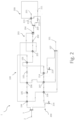
Figure 1 is a schematic view of a gas treating plant according to a possible embodiment of the invention; -
Figure 2 is a schematic view of a gas treating plant according to a further possible embodiment of the invention. - Referring to the attached figures, a plant for treating gas, particularly natural gas (typically comprising methane) is generally indicated by
reference 1. Theplant 1 receives at the inlet gas supplied by a transmission network (not shown in the figures) and, to this purpose, it comprises aninlet 2 connectable to said transmission network. The natural gas conveyed by the transmission network which enters theplant 1 is at a high pressure, typically between 35 and 75 bar. Theplant 1 comprises afirst plant portion 100 for decompressing a first fraction of the gas supplied by the transmission network and afirst outlet 101 for supplying the decompressed gas at an outlet predefined pressure from theplant 1 itself, particularly to a distribution network (not shown in the figures), which thefirst outlet 101 is connectable to. The decompressed gas delivered at thefirst outlet 101 is typically at a pressure of about 5 bar for methane gas, therefore at a pressure lower than the pressure of the transmission network. Moreover, preferably, the gas is supplied at the outlet at an outlet predefined temperature, which can be comprised between 5°C and 50°C, for example, generally greater than the temperature of the gas in the transmission network. - The
plant 1 comprises asecond plant portion 200 for liquefying a second fraction of the gas supplied by the transmission network and asecond outlet 201 for supplying the liquefied gas, typically LNG, flowing out theplant 1 itself, where the liquefied gas can be stored in tanks in order to be transported away. The liquefied gas supplied at thesecond outlet 201 is typically at a temperature of about -150°C and at a pressure comprised between about 4 and 5 bar in case of LNG. - Advantageously, the
plant 1 comprises aflow divider 3 for separating the gas entering through theinlet 2 into the first fraction destined to thefirst plant portion 100 and into the second fraction destined to thesecond plant portion 200. Preferably, theflow divider 3 is configured so that all the entering gas is delivered to the first 100 andsecond plant portions 200. Still more preferably, the first gas fraction is greater than the second gas fraction, in order to meet the working flow rate and the requirements of the distribution network. - In the following description and in the attached claims, the positions of the elements in the plant, will be indicated by the terms "upstream" and "downstream", which should be understood with reference to the direction of the gas flow inside the plant, as shown by the arrows drawn in the attached figures.
- With reference to
Figure 1 , thefirst plant portion 100 comprises athrottle valve 102 in which the first gas fraction from theflow divider 3 is subjected to a temperature and pressure reductions by generally remaining in the gas state. - Further, the
first plant portion 100 comprises afirst heat exchanger 103 establishing a thermal exchange relationship between the segment of thefirst plant portion 100 placed downstream thethrottle valve 102 and thesecond plant portion 200, wherein the first gas fraction is heated by the second gas fraction flowing in thesecond plant portion 200, which cools down accordingly. - Moreover, the
first plant portion 100 comprises asecond heat exchanger 104 establishing a thermal exchange relationship between the segment of thefirst portion 100 placed downstream thefirst heat exchanger 103 and the segment of thefirst plant portion 100 placed upstream thethrottle valve 102. In this way, the gas in thefirst plant portion 100 supplied by theflow divider 3 is precooled by the cooler gas coming from thethrottle valve 102 and by thefirst heat exchanger 103, which in turn is heated. Such gas from thesecond heat exchanger 104 can be supplied to thefirst outlet 101 and delivered therefrom to the distribution network. - Referring now to the
second plant portion 200, it comprises, as beforehand cited, afirst heat exchanger 103, in which the second gas fraction from theflow divider 3 is cooled down and at least partially liquefied. Thesecond plant portion 200, downstream thefirst exchanger 103, comprises athrottle valve 202 determining a further temperature and pressure reductions of the liquefied gas. The liquefied gas from thethrottle valve 202 therefore can be delivered to thesecond outlet 201, where it can be extracted, stored, and transported in a liquefied state. - As a person skilled in the art will clearly understand, the plant according to the invention substantially reduces the energy wastes present in the systems according to the prior art described in the introductory part. Actually, the
first plant portion 100 does not require heating burners and thesecond plant portion 200 does not need energy for the compression and for other energy-consuming methods used for liquefying. Such effect is obtained by the synergic relationship between the first and second plant portions, which exchange with each other heat by the above described modes. - Referring to
Figure 2 , some alternative embodiments of the plant according to the invention will be now described. The plant inFigure 2 comprises the same elements of the plants ofFigure 1 , as well as plural additional elements for a still better efficiency of the processes. It is observed that each of such additional elements can be provided alone or combined with one or more of the further additional elements and that the many alternative embodiments stemming from such combinations are not individually shown only for not making obscure the present description. - Referring to the
first plant portion 100, it comprises, downstream theflow divider 3, thethrottle valve 102, thefirst heat exchanger 103, and thesecond heat exchanger 104, according to what was beforehand described. - According to a possible embodiment, the
first plant portion 100 comprises achiller 105 located upstream thethrottle valve 102, preferably downstream thesecond heat exchanger 104. Thechiller 105 further pre-cools the first gas fraction before entering thethrottle valve 102. - According to an embodiment, the
first plant portion 100 comprises athird heat exchanger 106 placed downstream thesecond heat exchanger 104 establishing a thermal exchange relationship between the segment of thefirst plant portion 100 downstream thesecond heat exchanger 104 and the segment of thesecond plant portion 200 upstream thefirst heat exchanger 103. Thethird heat exchanger 106 determines a further heating of the first gas fraction downstream thesecond exchanger 104 and a pre-cooling of the second gas fraction upstream thefirst heat exchanger 103. - According to an embodiment, the
second plant portion 200 comprises asection 203 for recirculating a possible non-liquefied part of the second gas fraction exiting thethrottle valve 202. Advantageously,such recirculation section 203 comprises acondensate separator 204 downstream thethrottle valve 202.Such condensate separator 204 separates the liquefied part and the non-liquefied part of the second gas fraction exiting thethrottle valve 202 and conveys the liquefied part to thesecond outlet 201 and the non-liquefied part to thefirst outlet 101, where this latter can be mixed in amixer 107 with the first gas fraction from thesecond heat exchanger 104. The non-liquefied part, being effectively a waste of thesecond plant portion 200, can be advantageously recovered. - The non-liquefied part of the second gas fraction from the
condensate separator 204, at a low temperature, can be advantageously used for further pre-cooling the second gas fraction in the segment upstream thethrottle valve 202. For this matter, therecirculation section 203 can comprise afourth heat exchanger 205 establishing a thermal exchange relationship between the segment conveying the non-liquefied part of the second gas fraction downstream thecondensate separator 204 and the segment of thesecond plant portion 200 upstream thethrottle valve 202, preferably downstream thefirst heat exchanger 103. - Still more advantageously, the non-liquefied part of the second gas fraction from the
condensate separator 204 can be also used for further pre-cooling the first gas fraction in the segment upstream thethrottle valve 102. For this purpose, therecirculation section 203 can comprise afifth heat exchanger 206, preferably placed downstream thefourth heat exchanger 205, if provided, which establishes a thermal exchange relationship between the segment conveying the non-liquefied part of the second gas fraction downstream thecondensate separator 204 and the segment of thefirst plant portion 100 upstream thethrottle valve 102, preferably downstream thechiller 105, if provided. - Still more advantageously, the non-liquefied part of the second gas fraction from the
condensate separator 204 can be also used for further pre-cooling the second gas fraction in the segment upstream thethrottle valve 202. For this purpose, therecirculation section 203 can comprise asixth heat exchanger 207, for example placed downstream thethird heat exchanger 106 and upstream thefirst heat exchanger 103, which establishes a thermal exchange relationship between the segment of thesecond plant portion 200 which conveys the non-liquefied part of the second gas fraction downstream thecondensate separator 204 and the segment of thesecond plant portion 200 upstream thefirst heat exchanger 103. - According to an embodiment, the
second plant portion 200 comprises asecond recirculation section 208 placed downstream thethrottle valve 202, preferably downstream therecirculation section 203, if provided. Thesecond recirculation section 208 comprises asecond flow divider 209 separating the liquefied part of the second gas fraction into twodistinct branches first branch 210 leads to thesecond outlet 201, while the second branch leads to themixer 107 and from there to thefirst outlet 101. Thesecond branch 211 comprises asecond throttle valve 212, which subjects the liquid gas to a further throttling action, in which the liquid gas is subjected to further temperature and pressure reductions, and aseventh heat exchanger 213 which establishes a thermal exchange relationship between thefirst branch 210 and the segment of thesecond branch 211 downstream thesecond throttle valve 212, so that the liquefied gas circulating in thefirst branch 210 is further cooled down before flowing to thesecond outlet 201, while the liquefied gas downstream thesecond throttle valve 212 in thesecond segment 211 switches back to the gas state before flowing to themixer 107 and then being conveyed to thefirst outlet 101. Thus, also this latter gas fraction, which is effectively a waste of thesecond plant portion 200, can be advantageously recovered. - According to a further embodiment, the
second section 211 comprises aneighth heat exchanger 214 establishing a thermal exchange relationship between the second segment 211 (and preferably the portion of thesecond segment 211 downstream the seventh heat exchanger 213) and the segment of thesecond plant portion 200 upstream thefirst heat exchanger 103, preferably downstream thesixth heat exchanger 207. This further pre-cools the second gas fraction upstream thethrottle valve 202, and also heats the part of the second gas fraction flowing in thesecond segment 211 before it reaches themixer 107 and from there thefirst outlet 101. According to a possible embodiment, thesecond segment 211 comprises, downstream theseventh heat exchanger 213, preferably downstream theeighth heat exchanger 214, if provided, afirst compressor 215 suitable to increase the pressure, and also the temperature, of the gas flowing in thesecond segment 211 before reaching themixer 107 and from there thefirst outlet 101. - According to an embodiment, the
second plant portion 200 comprises asecond compressor 216 placed upstream thefirst heat exchanger 103, and preferably upstream thethird heat exchanger 103, if provided. - From the above given description, a person skilled in the art can appreciate that the plant according to the invention reduces the wastes described with reference to the plants according to the prior art due to an energy synergy between the first and the second plant portions. Indeed, the pressure difference of the process which is performed in the first plant portion is what is required by the process performed in the second plant portion, and the heat difference of the process performed in the second plant portion is what is required by the process performed in the first plant portion. Substantially, by combining the two processes, one process compensates the other one by eliminating the negative drawbacks which each process would have if not combined together.
- According to the invention, it is not necessary to counter the cooling of the gas in the first plant portion by preheating it by external boilers because the decompressed gas is recirculated, causing the gas to liquefy in the second plant portion, and at the same time the gas is suitably heated in order to be conveyed into the local distribution network.
- The person skilled in the art, in order to meet specific contingent needs, can introduce many additions, modifications, or substitutions of elements with other operatively equivalent ones to the described embodiments of the plant for treating gas, particularly natural gas, without falling out of the scope of the attached claims.
Claims (12)
- Plant (1) for treating gas, particularly natural gas, supplied by a transmission network, comprising:- a gas inlet (2) connectable to said transmission network;- a first plant portion (100) configured to decompress to a predefined outlet pressure a first fraction of the gas from the inlet (2) and to supply the decompressed gas at a first outlet (101);- a second plant portion (200) configured to liquefy a second fraction of the gas from the inlet (2) and to supply the liquefied gas at a second outlet (201), wherein the first plant portion (100) comprises:- a valve (102) for throttling the first gas fraction;- a first heat exchanger (103) establishing a thermal exchange relationship between the segment of the first plant portion (100) placed downstream the throttle valve (102) and the second plant portion (200);- a second heat exchanger (104) establishing a thermal exchange relationship between the segment of the first plant portion (100) placed downstream the first heat exchanger (103) and the segment of the first plant portion (100) placed upstream the throttle valve (102),and wherein the second plant portion (200) comprises, downstream the first heat exchanger (103), a valve (202) for throttling the second gas fraction.
- Plant (1) according to claim 1, wherein the first plant portion (100) comprises a chiller (105) placed upstream the throttle valve (102) of the first plant portion (100).
- Plant (1) according to claim 1 or 2, wherein the first plant portion (100) comprises a third heat exchanger (106) placed downstream the second heat exchanger (104) establishing a thermal exchange relationship between the segment of the first plant portion (100) downstream the second heat exchanger (104) and the segment of the second plant portion (200) upstream the first heat exchanger (103).
- Plant (1) according to any of the preceding claims, wherein the second plant portion (200) comprises a section (203) for recirculating a non-liquefied part of the second gas fraction exiting the throttle valve (202), said recirculation section (203) comprising a condensate separator (204) configured to separate a liquefied part and a non-liquefied part of the second gas fraction exiting the throttle valve (202) of the second plant portion (200) and to convey the liquefied part to the second outlet (201) and the non-liquefied part to the first outlet (101).
- Plant (1) according to claim 4, wherein said recirculation section (203) further comprises a fourth heat exchanger (205) establishing a thermal exchange relationship between the segment transporting the non-liquefied part of the second gas fraction downstream the condensate separator (204) and the segment of the second plant portion (200) upstream the throttle valve (202) of the second plant portion (200).
- Plant (1) according to claim 4 or 5, wherein said recirculation section (203) comprises a fifth heat exchanger (206) establishing a thermal exchange relationship between the segment transporting the non-liquefied part of the second gas fraction downstream the condensate separator (204) and the segment of the first plant portion (100) upstream the throttle valve (102) of the first plant portion (100).
- Plant (1) according to any of claims from 4 to 6, wherein said recirculation section (203) comprises a sixth heat exchanger (207) establishing a thermal exchange relationship between the segment transporting the non-liquefied part of the second gas fraction downstream the condensate separator (204) and the segment of the second plant portion (200) upstream the first heat exchanger (103).
- Plant (1) according to any of the preceding claims, wherein the second plant portion (200) comprises a second recirculation section (208) placed downstream the throttle valve (202) of the second plant portion (200), wherein said second recirculation section (208) comprises a first branch (210) for conveying a liquefied part of the second gas fraction from the throttle valve (202) of the second plant portion (200) to the second outlet (201), and a second branch connected to the first outlet (101), wherein the second branch (211) comprises a second throttle valve (212) and a seventh heat exchanger (213) establishing a thermal exchange relationship between the first branch (210) and the segment of the second branch (211) downstream the second throttle valve (212) of the second plant portion (200).
- Plant (1) according to claim 8, wherein the second branch (211) comprises an eighth heat exchanger (214) establishing a thermal exchange relationship between the portion of the second branch (211) downstream the seventh heat exchanger (213) and the segment of the second plant portion (200) upstream the first heat exchanger (103).
- Plant (1) according to claim 8 or 9, wherein the second segment (211) comprises a first compressor (215) downstream the seventh heat exchanger (213).
- Plant (1) according to any of the preceding claims, wherein the second plant portion (200) comprises a second compressor (216) placed upstream the first heat exchanger (103).
- Plant (1) according to any of the preceding claims, wherein in the segment between the first heat exchanger (103) and the second heat exchanger (104) the first plant portion (100) is fluidically separated from the second plant portion (200).
Applications Claiming Priority (1)
| Application Number | Priority Date | Filing Date | Title |
|---|---|---|---|
| IT102021000026921A IT202100026921A1 (en) | 2021-10-20 | 2021-10-20 | GAS TREATMENT PLANT, IN PARTICULAR NATURAL GAS, COMING FROM A TRANSPORT NETWORK |
Publications (3)
| Publication Number | Publication Date |
|---|---|
| EP4170224A1 true EP4170224A1 (en) | 2023-04-26 |
| EP4170224B1 EP4170224B1 (en) | 2025-01-29 |
| EP4170224C0 EP4170224C0 (en) | 2025-01-29 |
Family
ID=80113219
Family Applications (1)
| Application Number | Title | Priority Date | Filing Date |
|---|---|---|---|
| EP22198533.6A Active EP4170224B1 (en) | 2021-10-20 | 2022-09-28 | Plant for treating gas, particularly natural gas, supplied by a transmission network |
Country Status (5)
| Country | Link |
|---|---|
| US (1) | US12339061B2 (en) |
| EP (1) | EP4170224B1 (en) |
| ES (1) | ES3015204T3 (en) |
| IT (1) | IT202100026921A1 (en) |
| PL (1) | PL4170224T3 (en) |
Citations (4)
| Publication number | Priority date | Publication date | Assignee | Title |
|---|---|---|---|---|
| US20160003528A1 (en) * | 2013-02-20 | 2016-01-07 | Cryostar Sas | Station for reducing gas pressure and liquefying gas |
| RU2671665C1 (en) * | 2017-12-20 | 2018-11-06 | Андрей Владиславович Курочкин | Installation for natural gas liquefaction and method for operation thereof (options) |
| RU2691876C1 (en) * | 2018-10-23 | 2019-06-18 | Андрей Владиславович Курочкин | Plant for liquefied natural gas production (versions) |
| EP3839321A1 (en) * | 2019-12-17 | 2021-06-23 | NGV Autogas Spólka Z Ograniczona Odpowiedzialnoscia | Installation for compensating fluctuations in gas demand in natural gas networks and the method of implementing this compensation |
Family Cites Families (2)
| Publication number | Priority date | Publication date | Assignee | Title |
|---|---|---|---|---|
| US4778497A (en) * | 1987-06-02 | 1988-10-18 | Union Carbide Corporation | Process to produce liquid cryogen |
| JP5725856B2 (en) * | 2007-08-24 | 2015-05-27 | エクソンモービル アップストリーム リサーチ カンパニー | Natural gas liquefaction process |
-
2021
- 2021-10-20 IT IT102021000026921A patent/IT202100026921A1/en unknown
-
2022
- 2022-09-28 PL PL22198533.6T patent/PL4170224T3/en unknown
- 2022-09-28 EP EP22198533.6A patent/EP4170224B1/en active Active
- 2022-09-28 ES ES22198533T patent/ES3015204T3/en active Active
- 2022-10-07 US US17/961,808 patent/US12339061B2/en active Active
Patent Citations (4)
| Publication number | Priority date | Publication date | Assignee | Title |
|---|---|---|---|---|
| US20160003528A1 (en) * | 2013-02-20 | 2016-01-07 | Cryostar Sas | Station for reducing gas pressure and liquefying gas |
| RU2671665C1 (en) * | 2017-12-20 | 2018-11-06 | Андрей Владиславович Курочкин | Installation for natural gas liquefaction and method for operation thereof (options) |
| RU2691876C1 (en) * | 2018-10-23 | 2019-06-18 | Андрей Владиславович Курочкин | Plant for liquefied natural gas production (versions) |
| EP3839321A1 (en) * | 2019-12-17 | 2021-06-23 | NGV Autogas Spólka Z Ograniczona Odpowiedzialnoscia | Installation for compensating fluctuations in gas demand in natural gas networks and the method of implementing this compensation |
Also Published As
| Publication number | Publication date |
|---|---|
| IT202100026921A1 (en) | 2023-04-20 |
| EP4170224B1 (en) | 2025-01-29 |
| PL4170224T3 (en) | 2025-04-22 |
| US20230119458A1 (en) | 2023-04-20 |
| ES3015204T3 (en) | 2025-04-30 |
| EP4170224C0 (en) | 2025-01-29 |
| US12339061B2 (en) | 2025-06-24 |
Similar Documents
| Publication | Publication Date | Title |
|---|---|---|
| US4339253A (en) | Method of and system for liquefying a gas with low boiling temperature | |
| AU2007314748B2 (en) | Method and process plant for liquefaction of gas | |
| CN102667382B (en) | Methods of natural gas liquefaction and natural gas liquefaction plants utilizing multiple and varying gas streams | |
| CN104520660B (en) | System and method for natural gas liquefaction | |
| RU2395765C2 (en) | Plant and device for liquefaction of natural gas | |
| RU2719258C2 (en) | System and method of treating gas obtained during cryogenic liquid evaporation | |
| US11493239B2 (en) | Method for reducing the energy necessary for cooling natural gas into liquid natural gas using a non-freezing vortex tube as a precooling device | |
| CN107702430B (en) | Ship reliquefaction system and method | |
| JP2007511717A (en) | Apparatus and method for boil-off gas temperature control | |
| US10718564B2 (en) | Gas liquefaction apparatus and gas liquefaction method | |
| CN110044130B (en) | Boil-off gas reliquefaction device and LNG supply system provided with same | |
| JP2019510943A (en) | A system for processing the gas resulting from the evaporation of cryogenic liquid and supplying pressurized gas to a gas engine | |
| CN101137878A (en) | System and method for cooling a boil-off gas stream | |
| JP2016080279A (en) | Boil-off gas recovery system | |
| US20160003528A1 (en) | Station for reducing gas pressure and liquefying gas | |
| JP2016535211A (en) | Method and system for reliquefaction of boil-off gas | |
| EP4170224B1 (en) | Plant for treating gas, particularly natural gas, supplied by a transmission network | |
| Martinez et al. | Overview and status of the PIP-II cryogenic system | |
| US6170290B1 (en) | Refrigeration process and plant using a thermal cycle of a fluid having a low boiling point | |
| EP3045849A2 (en) | A plant for liquefying methane gas | |
| KR102951610B1 (en) | Integrated nitrogen rejection for liquefaction of natural gas | |
| CN108027197A (en) | The expansion storage method of natural gas liquefaction device liquefied natural gas stream and relevant device | |
| CN108027198B (en) | Method for cooling a process stream | |
| CN212481844U (en) | Air separation plant | |
| CN117588682B (en) | Novel refined carbon three-material storage and transportation system |
Legal Events
| Date | Code | Title | Description |
|---|---|---|---|
| PUAI | Public reference made under article 153(3) epc to a published international application that has entered the european phase |
Free format text: ORIGINAL CODE: 0009012 |
|
| STAA | Information on the status of an ep patent application or granted ep patent |
Free format text: STATUS: THE APPLICATION HAS BEEN PUBLISHED |
|
| AK | Designated contracting states |
Kind code of ref document: A1 Designated state(s): AL AT BE BG CH CY CZ DE DK EE ES FI FR GB GR HR HU IE IS IT LI LT LU LV MC MK MT NL NO PL PT RO RS SE SI SK SM TR |
|
| STAA | Information on the status of an ep patent application or granted ep patent |
Free format text: STATUS: REQUEST FOR EXAMINATION WAS MADE |
|
| 17P | Request for examination filed |
Effective date: 20230728 |
|
| RBV | Designated contracting states (corrected) |
Designated state(s): AL AT BE BG CH CY CZ DE DK EE ES FI FR GB GR HR HU IE IS IT LI LT LU LV MC MK MT NL NO PL PT RO RS SE SI SK SM TR |
|
| GRAP | Despatch of communication of intention to grant a patent |
Free format text: ORIGINAL CODE: EPIDOSNIGR1 |
|
| STAA | Information on the status of an ep patent application or granted ep patent |
Free format text: STATUS: GRANT OF PATENT IS INTENDED |
|
| INTG | Intention to grant announced |
Effective date: 20241106 |
|
| GRAS | Grant fee paid |
Free format text: ORIGINAL CODE: EPIDOSNIGR3 |
|
| GRAA | (expected) grant |
Free format text: ORIGINAL CODE: 0009210 |
|
| STAA | Information on the status of an ep patent application or granted ep patent |
Free format text: STATUS: THE PATENT HAS BEEN GRANTED |
|
| AK | Designated contracting states |
Kind code of ref document: B1 Designated state(s): AL AT BE BG CH CY CZ DE DK EE ES FI FR GB GR HR HU IE IS IT LI LT LU LV MC MK MT NL NO PL PT RO RS SE SI SK SM TR |
|
| REG | Reference to a national code |
Ref country code: GB Ref legal event code: FG4D |
|
| REG | Reference to a national code |
Ref country code: CH Ref legal event code: EP |
|
| REG | Reference to a national code |
Ref country code: DE Ref legal event code: R096 Ref document number: 602022010036 Country of ref document: DE |
|
| REG | Reference to a national code |
Ref country code: IE Ref legal event code: FG4D |
|
| U01 | Request for unitary effect filed |
Effective date: 20250225 |
|
| U07 | Unitary effect registered |
Designated state(s): AT BE BG DE DK EE FI FR IT LT LU LV MT NL PT RO SE SI Effective date: 20250303 |
|
| REG | Reference to a national code |
Ref country code: ES Ref legal event code: FG2A Ref document number: 3015204 Country of ref document: ES Kind code of ref document: T3 Effective date: 20250430 |
|
| U1N | Appointed representative for the unitary patent procedure changed after the registration of the unitary effect |
Representative=s name: GREGORJ S.R.L.; IT |
|
| PG25 | Lapsed in a contracting state [announced via postgrant information from national office to epo] |
Ref country code: RS Free format text: LAPSE BECAUSE OF FAILURE TO SUBMIT A TRANSLATION OF THE DESCRIPTION OR TO PAY THE FEE WITHIN THE PRESCRIBED TIME-LIMIT Effective date: 20250429 |
|
| PG25 | Lapsed in a contracting state [announced via postgrant information from national office to epo] |
Ref country code: IS Free format text: LAPSE BECAUSE OF FAILURE TO SUBMIT A TRANSLATION OF THE DESCRIPTION OR TO PAY THE FEE WITHIN THE PRESCRIBED TIME-LIMIT Effective date: 20250529 Ref country code: NO Free format text: LAPSE BECAUSE OF FAILURE TO SUBMIT A TRANSLATION OF THE DESCRIPTION OR TO PAY THE FEE WITHIN THE PRESCRIBED TIME-LIMIT Effective date: 20250429 |
|
| PG25 | Lapsed in a contracting state [announced via postgrant information from national office to epo] |
Ref country code: HR Free format text: LAPSE BECAUSE OF FAILURE TO SUBMIT A TRANSLATION OF THE DESCRIPTION OR TO PAY THE FEE WITHIN THE PRESCRIBED TIME-LIMIT Effective date: 20250129 |
|
| PG25 | Lapsed in a contracting state [announced via postgrant information from national office to epo] |
Ref country code: GR Free format text: LAPSE BECAUSE OF FAILURE TO SUBMIT A TRANSLATION OF THE DESCRIPTION OR TO PAY THE FEE WITHIN THE PRESCRIBED TIME-LIMIT Effective date: 20250430 |
|
| U20 | Renewal fee for the european patent with unitary effect paid |
Year of fee payment: 4 Effective date: 20250702 |
|
| PG25 | Lapsed in a contracting state [announced via postgrant information from national office to epo] |
Ref country code: SM Free format text: LAPSE BECAUSE OF FAILURE TO SUBMIT A TRANSLATION OF THE DESCRIPTION OR TO PAY THE FEE WITHIN THE PRESCRIBED TIME-LIMIT Effective date: 20250129 |
|
| PGFP | Annual fee paid to national office [announced via postgrant information from national office to epo] |
Ref country code: PL Payment date: 20250828 Year of fee payment: 4 |
|
| PG25 | Lapsed in a contracting state [announced via postgrant information from national office to epo] |
Ref country code: CZ Free format text: LAPSE BECAUSE OF FAILURE TO SUBMIT A TRANSLATION OF THE DESCRIPTION OR TO PAY THE FEE WITHIN THE PRESCRIBED TIME-LIMIT Effective date: 20250129 |
|
| PG25 | Lapsed in a contracting state [announced via postgrant information from national office to epo] |
Ref country code: SK Free format text: LAPSE BECAUSE OF FAILURE TO SUBMIT A TRANSLATION OF THE DESCRIPTION OR TO PAY THE FEE WITHIN THE PRESCRIBED TIME-LIMIT Effective date: 20250129 |
|
| PLBE | No opposition filed within time limit |
Free format text: ORIGINAL CODE: 0009261 |
|
| STAA | Information on the status of an ep patent application or granted ep patent |
Free format text: STATUS: NO OPPOSITION FILED WITHIN TIME LIMIT |
|
| REG | Reference to a national code |
Ref country code: CH Ref legal event code: L10 Free format text: ST27 STATUS EVENT CODE: U-0-0-L10-L00 (AS PROVIDED BY THE NATIONAL OFFICE) Effective date: 20251210 |
|
| 26N | No opposition filed |
Effective date: 20251030 |
|
| PGFP | Annual fee paid to national office [announced via postgrant information from national office to epo] |
Ref country code: ES Payment date: 20251210 Year of fee payment: 4 |
|
| REG | Reference to a national code |
Ref country code: CH Ref legal event code: H13 Free format text: ST27 STATUS EVENT CODE: U-0-0-H10-H13 (AS PROVIDED BY THE NATIONAL OFFICE) Effective date: 20260504 |
|
| PG25 | Lapsed in a contracting state [announced via postgrant information from national office to epo] |
Ref country code: MC Free format text: LAPSE BECAUSE OF FAILURE TO SUBMIT A TRANSLATION OF THE DESCRIPTION OR TO PAY THE FEE WITHIN THE PRESCRIBED TIME-LIMIT Effective date: 20250129 |
|
| PG25 | Lapsed in a contracting state [announced via postgrant information from national office to epo] |
Ref country code: CH Free format text: LAPSE BECAUSE OF NON-PAYMENT OF DUE FEES Effective date: 20250930 Ref country code: IE Free format text: LAPSE BECAUSE OF NON-PAYMENT OF DUE FEES Effective date: 20250928 |