EP4170192A1 - Strut bearing device, and vehicle strut suspension - Google Patents
Strut bearing device, and vehicle strut suspension Download PDFInfo
- Publication number
- EP4170192A1 EP4170192A1 EP22202360.8A EP22202360A EP4170192A1 EP 4170192 A1 EP4170192 A1 EP 4170192A1 EP 22202360 A EP22202360 A EP 22202360A EP 4170192 A1 EP4170192 A1 EP 4170192A1
- Authority
- EP
- European Patent Office
- Prior art keywords
- lower case
- engagement
- spring sheet
- strut bearing
- case
- Prior art date
- Legal status (The legal status is an assumption and is not a legal conclusion. Google has not performed a legal analysis and makes no representation as to the accuracy of the status listed.)
- Pending
Links
Images






Classifications
-
- F—MECHANICAL ENGINEERING; LIGHTING; HEATING; WEAPONS; BLASTING
- F16—ENGINEERING ELEMENTS AND UNITS; GENERAL MEASURES FOR PRODUCING AND MAINTAINING EFFECTIVE FUNCTIONING OF MACHINES OR INSTALLATIONS; THERMAL INSULATION IN GENERAL
- F16C—SHAFTS; FLEXIBLE SHAFTS; ELEMENTS OR CRANKSHAFT MECHANISMS; ROTARY BODIES OTHER THAN GEARING ELEMENTS; BEARINGS
- F16C19/00—Bearings with rolling contact, for exclusively rotary movement
- F16C19/02—Bearings with rolling contact, for exclusively rotary movement with bearing balls essentially of the same size in one or more circular rows
- F16C19/10—Bearings with rolling contact, for exclusively rotary movement with bearing balls essentially of the same size in one or more circular rows for axial load mainly
-
- B—PERFORMING OPERATIONS; TRANSPORTING
- B60—VEHICLES IN GENERAL
- B60G—VEHICLE SUSPENSION ARRANGEMENTS
- B60G15/00—Resilient suspensions characterised by arrangement, location or type of combined spring and vibration damper, e.g. telescopic type
- B60G15/02—Resilient suspensions characterised by arrangement, location or type of combined spring and vibration damper, e.g. telescopic type having mechanical spring
- B60G15/06—Resilient suspensions characterised by arrangement, location or type of combined spring and vibration damper, e.g. telescopic type having mechanical spring and fluid damper
- B60G15/067—Resilient suspensions characterised by arrangement, location or type of combined spring and vibration damper, e.g. telescopic type having mechanical spring and fluid damper characterised by the mounting on the vehicle body or chassis of the spring and damper unit
- B60G15/068—Resilient suspensions characterised by arrangement, location or type of combined spring and vibration damper, e.g. telescopic type having mechanical spring and fluid damper characterised by the mounting on the vehicle body or chassis of the spring and damper unit specially adapted for MacPherson strut-type suspension
-
- F—MECHANICAL ENGINEERING; LIGHTING; HEATING; WEAPONS; BLASTING
- F16—ENGINEERING ELEMENTS AND UNITS; GENERAL MEASURES FOR PRODUCING AND MAINTAINING EFFECTIVE FUNCTIONING OF MACHINES OR INSTALLATIONS; THERMAL INSULATION IN GENERAL
- F16C—SHAFTS; FLEXIBLE SHAFTS; ELEMENTS OR CRANKSHAFT MECHANISMS; ROTARY BODIES OTHER THAN GEARING ELEMENTS; BEARINGS
- F16C35/00—Rigid support of bearing units; Housings, e.g. caps, covers
- F16C35/04—Rigid support of bearing units; Housings, e.g. caps, covers in the case of ball or roller bearings
- F16C35/06—Mounting or dismounting of ball or roller bearings; Fixing them onto shaft or in housing
-
- B—PERFORMING OPERATIONS; TRANSPORTING
- B60—VEHICLES IN GENERAL
- B60G—VEHICLE SUSPENSION ARRANGEMENTS
- B60G2204/00—Indexing codes related to suspensions per se or to auxiliary parts
- B60G2204/10—Mounting of suspension elements
- B60G2204/12—Mounting of springs or dampers
- B60G2204/128—Damper mount on vehicle body or chassis
-
- B—PERFORMING OPERATIONS; TRANSPORTING
- B60—VEHICLES IN GENERAL
- B60G—VEHICLE SUSPENSION ARRANGEMENTS
- B60G2204/00—Indexing codes related to suspensions per se or to auxiliary parts
- B60G2204/40—Auxiliary suspension parts; Adjustment of suspensions
- B60G2204/418—Bearings, e.g. ball or roller bearings
-
- F—MECHANICAL ENGINEERING; LIGHTING; HEATING; WEAPONS; BLASTING
- F16—ENGINEERING ELEMENTS AND UNITS; GENERAL MEASURES FOR PRODUCING AND MAINTAINING EFFECTIVE FUNCTIONING OF MACHINES OR INSTALLATIONS; THERMAL INSULATION IN GENERAL
- F16C—SHAFTS; FLEXIBLE SHAFTS; ELEMENTS OR CRANKSHAFT MECHANISMS; ROTARY BODIES OTHER THAN GEARING ELEMENTS; BEARINGS
- F16C19/00—Bearings with rolling contact, for exclusively rotary movement
- F16C19/02—Bearings with rolling contact, for exclusively rotary movement with bearing balls essentially of the same size in one or more circular rows
- F16C19/14—Bearings with rolling contact, for exclusively rotary movement with bearing balls essentially of the same size in one or more circular rows for both radial and axial load
- F16C19/16—Bearings with rolling contact, for exclusively rotary movement with bearing balls essentially of the same size in one or more circular rows for both radial and axial load with a single row of balls
- F16C19/163—Bearings with rolling contact, for exclusively rotary movement with bearing balls essentially of the same size in one or more circular rows for both radial and axial load with a single row of balls with angular contact
-
- F—MECHANICAL ENGINEERING; LIGHTING; HEATING; WEAPONS; BLASTING
- F16—ENGINEERING ELEMENTS AND UNITS; GENERAL MEASURES FOR PRODUCING AND MAINTAINING EFFECTIVE FUNCTIONING OF MACHINES OR INSTALLATIONS; THERMAL INSULATION IN GENERAL
- F16C—SHAFTS; FLEXIBLE SHAFTS; ELEMENTS OR CRANKSHAFT MECHANISMS; ROTARY BODIES OTHER THAN GEARING ELEMENTS; BEARINGS
- F16C2208/00—Plastics; Synthetic resins, e.g. rubbers
- F16C2208/02—Plastics; Synthetic resins, e.g. rubbers comprising fillers, fibres
- F16C2208/04—Glass fibres
-
- F—MECHANICAL ENGINEERING; LIGHTING; HEATING; WEAPONS; BLASTING
- F16—ENGINEERING ELEMENTS AND UNITS; GENERAL MEASURES FOR PRODUCING AND MAINTAINING EFFECTIVE FUNCTIONING OF MACHINES OR INSTALLATIONS; THERMAL INSULATION IN GENERAL
- F16C—SHAFTS; FLEXIBLE SHAFTS; ELEMENTS OR CRANKSHAFT MECHANISMS; ROTARY BODIES OTHER THAN GEARING ELEMENTS; BEARINGS
- F16C2208/00—Plastics; Synthetic resins, e.g. rubbers
- F16C2208/20—Thermoplastic resins
- F16C2208/60—Polyamides [PA]
-
- F—MECHANICAL ENGINEERING; LIGHTING; HEATING; WEAPONS; BLASTING
- F16—ENGINEERING ELEMENTS AND UNITS; GENERAL MEASURES FOR PRODUCING AND MAINTAINING EFFECTIVE FUNCTIONING OF MACHINES OR INSTALLATIONS; THERMAL INSULATION IN GENERAL
- F16C—SHAFTS; FLEXIBLE SHAFTS; ELEMENTS OR CRANKSHAFT MECHANISMS; ROTARY BODIES OTHER THAN GEARING ELEMENTS; BEARINGS
- F16C2226/00—Joining parts; Fastening; Assembling or mounting parts
- F16C2226/50—Positive connections
- F16C2226/62—Positive connections with pins, bolts or dowels
-
- F—MECHANICAL ENGINEERING; LIGHTING; HEATING; WEAPONS; BLASTING
- F16—ENGINEERING ELEMENTS AND UNITS; GENERAL MEASURES FOR PRODUCING AND MAINTAINING EFFECTIVE FUNCTIONING OF MACHINES OR INSTALLATIONS; THERMAL INSULATION IN GENERAL
- F16C—SHAFTS; FLEXIBLE SHAFTS; ELEMENTS OR CRANKSHAFT MECHANISMS; ROTARY BODIES OTHER THAN GEARING ELEMENTS; BEARINGS
- F16C2240/00—Specified values or numerical ranges of parameters; Relations between them
- F16C2240/40—Linear dimensions, e.g. length, radius, thickness, gap
- F16C2240/44—Hole or pocket sizes
-
- F—MECHANICAL ENGINEERING; LIGHTING; HEATING; WEAPONS; BLASTING
- F16—ENGINEERING ELEMENTS AND UNITS; GENERAL MEASURES FOR PRODUCING AND MAINTAINING EFFECTIVE FUNCTIONING OF MACHINES OR INSTALLATIONS; THERMAL INSULATION IN GENERAL
- F16C—SHAFTS; FLEXIBLE SHAFTS; ELEMENTS OR CRANKSHAFT MECHANISMS; ROTARY BODIES OTHER THAN GEARING ELEMENTS; BEARINGS
- F16C2326/00—Articles relating to transporting
- F16C2326/01—Parts of vehicles in general
- F16C2326/05—Vehicle suspensions, e.g. bearings, pivots or connecting rods used therein
-
- F—MECHANICAL ENGINEERING; LIGHTING; HEATING; WEAPONS; BLASTING
- F16—ENGINEERING ELEMENTS AND UNITS; GENERAL MEASURES FOR PRODUCING AND MAINTAINING EFFECTIVE FUNCTIONING OF MACHINES OR INSTALLATIONS; THERMAL INSULATION IN GENERAL
- F16C—SHAFTS; FLEXIBLE SHAFTS; ELEMENTS OR CRANKSHAFT MECHANISMS; ROTARY BODIES OTHER THAN GEARING ELEMENTS; BEARINGS
- F16C33/00—Parts of bearings; Special methods for making bearings or parts thereof
- F16C33/72—Sealings
- F16C33/76—Sealings of ball or roller bearings
- F16C33/761—Sealings of ball or roller bearings specifically for bearings with purely axial load
Definitions
- the present invention relates to a strut bearing device for use in a vehicle strut suspension.
- a suspension that supports a wheel on the body of a vehicle by means of a coil spring and includes a shock absorber for absorbing vertical vibrations
- a strut suspension in which an extendable strut containing a shock absorber is fixed to an axle.
- the strut suspension is widely used, mainly, for a front wheel of an automobile.
- a strut bearing device for supporting, in an axial direction, a spring support component (e.g., a bottom retainer 7 of Patent Literature (PTL) 1 and a bottom cup 16 of PTL 2) for supporting an upper end of a coil spring (e.g., a coil spring 2 of PTL 1 and a coil spring 17 of PTL 2), and a lower case that is included in a strut bearing and is made of a synthetic resin (e.g., a bottom cover 5 of PTL 1 and a bottom cap 15 of PTL 2) (see PTLS 1 and 2, for example).
- a spring support component e.g., a bottom retainer 7 of Patent Literature (PTL) 1 and a bottom cup 16 of PTL 2
- a coil spring e.g., a coil spring 2 of PTL 1 and a coil spring 17 of PTL 2
- a lower case that is included in a strut bearing and is made of a synthetic resin (e.g., a bottom cover 5 of PTL
- the spring support component and the lower case are held in the axial direction by friction generated by an elastically deformed resin component that is elastically deformed so as to be in contact with a metal component.
- a tongue piece 15 provided in an axially inner surface 11c of a body 11 that is included in a bottom cover 5 and is made of a synthetic resin, comes into contact with an inner peripheral surface of an axial portion 17a of a strut 17 that is included in the bottom retainer 7 and is made of steel ( FIGS. 1 and 2 ).
- a lug 20 provided in the inner peripheral surface of the axial portion 17a comes into contact with the axially inner surface 11c of the body 11 ( FIGS. 3 and 4 ).
- the spring support component and the lower case are held in the axial direction by providing a plurality of hooks 15f extending downward in the axial direction in the bottom cap 15 made of a synthetic resin. Specifically, an end portion 15g of each of the hooks 15f interferes with a small-diameter free end of a radial portion 16c of the bottom cup 16 made of steel, to thereby fasten the bottom cap 15 and the bottom cup 16 in the axial direction ( FIGS. 1-2 , and FIGS. 5-6 ).
- PTL 1 discloses a method of holding the spring support component and the lower case in the axial direction.
- a tightening strength between the bottom retainer 7 and the bottom cover 5 is lowered due to aging deterioration (creep) of a resin component. This may cause a separation-preventing ability of the bottom retainer 7 and the bottom cover 5 to be lowered or to be lost.
- PTL 2 discloses a method of holding the spring support component and the lower case in the axial direction.
- relative movement of the bottom cap 15 and the bottom cup 16 in the circumferential direction is not restricted, so that the bottom cap 15 and the bottom cup 16 slide in the circumferential direction. This causes a contact surface, with the bottom cup 16 made of steel, in the bottom cap 15 made of a synthetic resin, to be worn away.
- a purpose of the present invention is to provide a strut bearing device that can hold a spring support component and a lower case in the axial direction, without fail.
- Another purpose of the present invention is to provide a strut bearing device in which a contact surface, with the spring support component made of steel, in the lower case made of a synthetic resin is not worn away.
- a strut bearing device includes a strut bearing; and an upper spring sheet that is a spring support component supporting an upper end of a coil spring, in which the strut bearing includes: an upper case and a lower case; an upper raceway ring held by the upper case; a lower raceway ring held by the lower case; and a rolling element that rolls between the upper raceway ring and the lower raceway ring, the upper case and the lower case are made of a synthetic resin, the upper spring sheet is made of steel, the upper spring sheet has a cylindrical part and a disc part, the cylindrical part has, at an upper part thereof, one of an engagement hole penetrated in a radial direction and an engagement recess having a hollowed inner peripheral surface, the lower case has a cylindrical member fitted along an inner peripheral surface of the upper part of the cylindrical part, the cylindrical member has, at an outer peripheral surface thereof, an engagement projection engaged with the engagement hole or the engagement recess, and relative movement of the upper spring sheet and
- the engagement projection of the cylindrical member in the lower case is engaged with the engagement hole or the engagement recess, of the cylindrical part in the upper spring sheet.
- the engagement projection of the cylindrical member in the lower case is engaged with the engagement hole or the engagement recess of the cylindrical part in the upper spring sheet.
- the engagement projection of the lower case has a top face that is a substantially horizontal surface or a side face of a column extending in a substantially horizontal direction, and the engagement projection has a bottom face that is an inclined face reducing a diameter thereof as approaching a lower side.
- the inclined surface of the bottom face of the engaged projection in the lower case made of a synthetic resin is fitted along from the upper part of the inner peripheral surface of the cylindrical part of the upper spring sheet made of steel so as to allow the lower case to be elastically deformed and easily fall downward relative to the upper spring sheet. Therefore, the engagement projection of the lower case can be easily engaged with the engagement hole or the engagement recess, of the upper spring sheet.
- the top face of the engagement projection is stopped at an upper wall of the engagement hole or the engagement recess, in a state where the engagement projection is engaged in the engagement hole or the engagement recess.
- the top face is a substantially horizontal surface or a side face of a column extending in a substantially horizontal direction. Therefore, separation between the upper spring sheet that is a spring support component and the lower case in the axial direction can be surely prevented.
- a strut bearing device includes a strut bearing; and an upper spring sheet that is a spring support component supporting an upper end of a coil spring, in which the strut bearing includes: an upper case and a lower case; an upper raceway ring held by the upper case; a lower raceway ring held by the lower case; and a rolling element that rolls between the upper raceway ring and the lower raceway ring, the upper case and the lower case are made of a synthetic resin, the upper spring sheet is made of steel, the upper spring sheet has a cylindrical part and a disc part, and the cylindrical part has, at an upper part thereof, an engagement projection that projects in a radially inward direction, the lower case has a cylindrical member fitted along an inner peripheral surface of the upper part of the cylindrical part, the cylindrical member has one of an engagement hole penetrated in a radial direction and an engagement recess that has a hollowed outer peripheral surface, the engagement hole and the engagement recess being engaged with the
- the engagement hole or the engagement recess of the cylindrical member in the lower case is engaged with the engagement projection of the cylindrical part in the upper spring sheet, thereby restricting the relative movement of the upper spring sheet and the lower case in the axial direction. Therefore, the separation between the upper spring sheet that is a spring support component and the lower case in the axial direction can be prevented, so that the upper spring sheet and the lower case can be surely held.
- the engagement hole or the engagement recess of the cylindrical member in the lower case is engaged with the engagement projection of the cylindrical part in the upper spring sheet, thereby restricting the relative movement of the upper spring sheet and the lower case in the axial direction.
- the lower case can be positioned relative to the upper spring sheet in the circumferential direction, so that the upper spring sheet and the lower case do not slide in the circumferential direction. Therefore, the contact surface with the upper spring sheet made of steel, in the lower case made of a synthetic resin, is not worn away.
- a vehicle strut suspension according to the present invention includes the strut bearing device.
- the upper spring sheet that is a spring support component and the lower case can be surely held in the axial direction, and the contact surface with the upper spring sheet made of steel, in the lower case made of a synthetic resin, is not worn away.
- a direction parallel to a rotation axis O (see FIG. 1 ) of a strut bearing device 1 is referred to as an "axial direction” (see an arrow J in FIG. 1 , for example)
- a direction orthogonal to the rotation axis O is referred to as a "radial direction” (see an arrow R in FIG. 1 , for example)
- views seen in the radial direction R are set as front views.
- a radial direction approaching the rotation axis O is referred to as a "radially inward direction” (see an arrow RI in FIG. 1 , for example), and a radial direction going away from the rotation axis O is referred to as a "radially outward direction” (see an arrow RO in FIG. 1 , for example).
- a horizontal direction that is orthogonal to the radial direction extending from the rotation axis O is referred to as a "circumferential direction” (see an arrow E in FIG. 3 , for example).
- a vehicle strut suspension S shown in the schematic view with the partially cross-sectional view of FIG. 1 is used in a state where an extendable strut 10 containing a shock absorber is fixed to an axle (not shown) and an upper mount 16 is fixed to the body of a vehicle.
- the strut suspension S is provided with, at its upper portion, a strut bearing device 1 that is swingably rotated in proportion to a direction change of a steering wheel in accordance with steering operation, while supporting the vehicle body.
- a swing angle of the strut bearing 1 is defined so as to correspond to an allowable steering angle of a wheel, and is set in a range of 40° or more and 50° or less, for example.
- a coil spring 11 serving as a suspension spring, and a dust boot 12 used for protecting an oil seal of the shock absorber from foreign substances such as sand are provided on an outer-diameter side of the strut 10 in the radially outward direction RO.
- the strut suspension S includes a spring support component 13 that supports an upper end of the coil spring 11.
- the spring support component 13 includes an upper spring sheet 14 and an upper insulator 15, as shown in the vertical cross-sectional view of FIG. 2A .
- the strut bearing device A includes a strut bearing 1 and an upper spring sheet 14 that is a spring support component 13 that supports the upper end of the coil spring 11.
- the strut bearing 1 includes an upper case 2, a lower case 3, an upper raceway ring 4, a lower raceway ring 5, rolling elements 6, a retainer 7, an inner-diameter side seal 8, an outer-diameter side seal 9, and so on.
- the upper case 2 is fixed to an upper end portion of the strut 10, and the lower case 3 receives the upper spring sheet 14 from above.
- the upper raceway ring 4 is held by the upper case 2, and the lower raceway ring 5 is held by the lower case 3.
- the rolling elements 6 roll between the upper raceway ring 4 and the lower raceway ring 5, and the retainer 7 holds each of the rolling elements 6 so that the adjacent rolling elements 6 do not come into contact with each other.
- the inner-diameter side seal 8 is positioned in a radially inward direction RI relative to the rolling elements 6, and the outer-diameter side seal 9 is positioned in a radially outward direction RO relative to the rolling elements 6.
- the upper raceway ring 4, the lower raceway ring 5, and the upper spring sheet 14 are made of steel, and are formed in a manner that a steel plate is subjected to press working, and then undergoes quenching to be hardened.
- the upper case 2 and the lower case 3 are made of a synthetic resin, and the inner-diameter side seal 8 and the outer-diameter side seal 9 are made of elastomer.
- the synthetic resin used for the upper case 2 and the lower case 3 is polyamide (PA66, PA46, PA612, PA6, PA9T, PA10T, and so on) and contains 20 to 60% by weight of glass fiber (GF) as reinforced fiber, for example.
- GF glass fiber
- the elastomer used for the inner-diameter side seal 8 and the outer-diameter side seal 9 is thermoplastic elastomers (TPE) including TPS (styrene-based elastomer), TPO (olefin-based elastomer), TPU (urethane-based elastomer), TPA (amide-based elastomer), TPEE (ester-based elastomer), and so on.
- Rubber materials include nitrile rubber (NBR), hydrogenated nitrile rubber (HNBR), acrylic rubber (ACM), ethylene-acrylic rubber (AEM), fluorine rubber (FKM, FPM), silicone rubber (VQM), and so on.
- One of the rubber materials may be used, or two or more of the rubber materials may be suitably blended and used.
- the upper case 2 and the lower case 3 are molded through injection molding. Specifically, the upper case 2 is molded in a manner that a molten synthetic resin is injected, into a cavity for molding the upper case 2, through a gate of a mold having the cavity. Similarly, the lower case 3 is molded in a manner that the molten synthetic resin is injected, into a cavity for molding the lower case 3, through a gate of a mold having the cavity.
- the upper spring sheet 14 has a cylindrical part 14A and a disc part 14B extending in the radially outward direction RO from an upper end portion of the cylindrical part 14A.
- the cylindrical part 14A has, at an upper part thereof, a square hole 21 that penetrates in a radial direction R to serve as an engagement hole B.
- the lower case 3 has a cylindrical member 17 fitted along an inner peripheral surface of the upper part of the cylindrical part 14A of the upper spring sheet 14.
- the cylindrical member 17 has, at its outer peripheral surface 17A, a square-shaped projection piece 18 serving as an engagement projection D that is to engage with the square hole 21 serving as the engagement hole B of the upper spring sheet 14.
- a top face of the square-shaped projection piece 18 is a substantially horizontal surface H1
- a bottom face of the square-shaped projection piece 18 is an inclined surface F that reduces its diameter as approaching a lower side.
- the upper spring sheet 14 and the lower case 3 are brought close to each other, and the inclined surface F in the bottom face of the square-shaped projection piece 18 serving as the engagement projection D in the lower case 3 made of a synthetic resin is fitted along from the upper part of the inner peripheral surface of the cylindrical part 14A of the upper spring sheet 14 made of the steel with elastically deforming the lower case 3, thereby easily lowering the lower case 3 down along the upper spring sheet 14.
- the square-shaped projection piece 18 serving as the engagement projection D in the lower case 3 can be easily engaged with the square hole 21 serving as the engagement hole B of the upper spring sheet 14.
- FIGS. 2A and 2B relative movement of the upper spring sheet 14 and the lower case 3 in the axial direction J is restricted in the state where the square-shaped projection piece 18 is engaged with the square hole 21.
- the top face that is the substantially horizontal surface H1 of the square-shaped projection piece 18 is stopped at an upper wall K of the square hole 21. Therefore, separation between the upper spring sheet 14 serving as the spring support component 13 and the lower case 3 in the axial direction J can be surely prevented.
- T is 2 mm, for example, the radial height G of the square-shaped projection piece 18 should be around 0.5 to 1.0 mm, for example.
- the square-shaped projection piece 18 is engaged with the square hole 21 having a shape shown in the perspective view of FIG. 3 and the front view of FIG. 4 , in a state where the square-shaped projection piece 18 of the lower case 3 is engaged with the square hole 21 of the upper spring sheet 14 as shown in the vertical cross-sectional views of FIGS. 2A and 2B . Therefore, the relative movement of the upper spring sheet 14 and the lower case 3 in the circumferential direction E shown in FIG. 3 is restricted.
- the lower case 3 can be positioned relative to the upper spring sheet 14 in the circumferential direction E, so that the upper spring sheet 14 and the lower case 3 do not slide in the circumferential direction E. Therefore, a contact surface, with the upper spring sheet 14 made of steel, of the lower case 3 made of a synthetic resin is not worn away.
- the engagement hole B of the upper spring sheet 14 and the engagement projection D of the lower case 3 may respectively be a long hole 22 and long-circle shaped projection piece 19 as shown in the front view of FIG. 5 , and may respectively be a round hole 23 and a round shaped projection piece 20 as shown in the front view of FIG. 6 .
- the top face of the round shaped projection piece 20 shown in FIG. 6 is not the substantially horizontal surface H1, but a side surface H2 of a column extending in the substantially horizontal direction.
- the cylindrical part 14A of the upper spring sheet 14 may have an engagement recess C having a hollowed inner peripheral surface, instead of the engagement hole B.
- the relative movement of the upper spring sheet 14 and the lower case 3 in the axial direction J and the circumferential direction E is also restricted in a state where the engagement projection D is engaged with the engagement recess C.
- the reference sign K in FIG. 7B indicates an upper wall of the engagement recess C.
- relationship among: the radial height G that is a projecting height of the engagement projection D in the radially outward direction RO; a radial depth L of the engagement recess C; and the thickness T of the cylindrical part 14A is expressed as G ⁇ L ⁇ T.
- T is 2 mm, for example, L should be around 1.0 to 1.5 mm, for example, and G should be less than L, e.g., a level of 0.5 to 1.0 mm.
- the engagement hole B penetrating in the radial direction R may be used instead of the engagement recess C.
- an engagement projection M projecting in the radially inward direction RI may be provided at the upper part of the cylindrical part 14A of the upper spring sheet 14, and an engagement hole N that is to engage with the engagement projection M and penetrates in the radial direction R may be provided in the cylindrical member 17 of the lower case 3.
- an engagement recess having a hollowed outer peripheral surface 17A may be provided in the cylindrical body 17 of the lower case 3, so as to be engaged with the engagement projection M.
Landscapes
- Engineering & Computer Science (AREA)
- General Engineering & Computer Science (AREA)
- Mechanical Engineering (AREA)
- Vehicle Body Suspensions (AREA)
- Fluid-Damping Devices (AREA)
- Mounting Of Bearings Or Others (AREA)
- Rolling Contact Bearings (AREA)
Abstract
Description
- The present invention relates to a strut bearing device for use in a vehicle strut suspension.
- As a suspension that supports a wheel on the body of a vehicle by means of a coil spring and includes a shock absorber for absorbing vertical vibrations, there is a strut suspension in which an extendable strut containing a shock absorber is fixed to an axle. The strut suspension is widely used, mainly, for a front wheel of an automobile.
- As a strut bearing device used in an upper portion of the strut suspension, there is a strut bearing device for supporting, in an axial direction, a spring support component (e.g., a
bottom retainer 7 of Patent Literature (PTL) 1 and abottom cup 16 of PTL 2) for supporting an upper end of a coil spring (e.g., acoil spring 2 of PTL 1 and acoil spring 17 of PTL 2), and a lower case that is included in a strut bearing and is made of a synthetic resin (e.g., abottom cover 5 of PTL 1 and abottom cap 15 of PTL 2) (seePTLS 1 and 2, for example). - In PTL 1, the spring support component and the lower case are held in the axial direction by friction generated by an elastically deformed resin component that is elastically deformed so as to be in contact with a metal component. Specifically, a
tongue piece 15 provided in an axially inner surface 11c of abody 11 that is included in abottom cover 5 and is made of a synthetic resin, comes into contact with an inner peripheral surface of an axial portion 17a of astrut 17 that is included in thebottom retainer 7 and is made of steel (FIGS. 1 and2 ). Alternatively, alug 20 provided in the inner peripheral surface of the axial portion 17a comes into contact with the axially inner surface 11c of the body 11 (FIGS. 3 and4 ). - In
PTL 2, the spring support component and the lower case are held in the axial direction by providing a plurality of hooks 15f extending downward in the axial direction in thebottom cap 15 made of a synthetic resin. Specifically, an end portion 15g of each of the hooks 15f interferes with a small-diameter free end of a radial portion 16c of thebottom cup 16 made of steel, to thereby fasten thebottom cap 15 and thebottom cup 16 in the axial direction (FIGS. 1-2 , andFIGS. 5-6 ). -
- [PTL 1]
US Patent No. 8,496,383 - [PTL 2]
US Patent No. 6,814,496 - PTL 1 discloses a method of holding the spring support component and the lower case in the axial direction. In the method, a tightening strength between the
bottom retainer 7 and thebottom cover 5 is lowered due to aging deterioration (creep) of a resin component. This may cause a separation-preventing ability of thebottom retainer 7 and thebottom cover 5 to be lowered or to be lost. -
PTL 2 discloses a method of holding the spring support component and the lower case in the axial direction. In the method, relative movement of thebottom cap 15 and thebottom cup 16 in the circumferential direction is not restricted, so that thebottom cap 15 and thebottom cup 16 slide in the circumferential direction. This causes a contact surface, with thebottom cup 16 made of steel, in thebottom cap 15 made of a synthetic resin, to be worn away. - A purpose of the present invention is to provide a strut bearing device that can hold a spring support component and a lower case in the axial direction, without fail. Another purpose of the present invention is to provide a strut bearing device in which a contact surface, with the spring support component made of steel, in the lower case made of a synthetic resin is not worn away.
- In order to solve the problems described above, a strut bearing device according to the present invention includes a strut bearing; and an upper spring sheet that is a spring support component supporting an upper end of a coil spring, in which the strut bearing includes: an upper case and a lower case; an upper raceway ring held by the upper case; a lower raceway ring held by the lower case; and a rolling element that rolls between the upper raceway ring and the lower raceway ring, the upper case and the lower case are made of a synthetic resin, the upper spring sheet is made of steel, the upper spring sheet has a cylindrical part and a disc part, the cylindrical part has, at an upper part thereof, one of an engagement hole penetrated in a radial direction and an engagement recess having a hollowed inner peripheral surface, the lower case has a cylindrical member fitted along an inner peripheral surface of the upper part of the cylindrical part, the cylindrical member has, at an outer peripheral surface thereof, an engagement projection engaged with the engagement hole or the engagement recess, and relative movement of the upper spring sheet and the lower case in an axial direction and in a circumferential direction is restricted in a state where the engagement projection is engaged with the engagement hole or the engagement recess.
- According to such a configuration of the strut bearing device of the present invention, the engagement projection of the cylindrical member in the lower case is engaged with the engagement hole or the engagement recess, of the cylindrical part in the upper spring sheet. With this configuration, the relative movement of the upper spring sheet and the lower case in the axial direction is restricted. Therefore, the upper spring sheet that is a spring support component and the lower case are prevented from being separated in the axial direction, so as to be surely held in the axial direction.
- According to the configuration of the strut bearing device of the present invention, the engagement projection of the cylindrical member in the lower case is engaged with the engagement hole or the engagement recess of the cylindrical part in the upper spring sheet. With this configuration, the relative movement of the upper spring sheet and the lower case in the circumferential direction is restricted. Thus, the lower case can be positioned relative to the upper spring sheet in the circumferential direction, thereby preventing the upper spring sheet and the lower case from sliding in the circumferential direction. Therefore, the contact face, with the upper spring sheet made of steel, in the lower case made of the synthetic resin is not worn away.
- Here, it is preferable that the engagement projection of the lower case has a top face that is a substantially horizontal surface or a side face of a column extending in a substantially horizontal direction, and the engagement projection has a bottom face that is an inclined face reducing a diameter thereof as approaching a lower side.
- According to such a configuration of the strut bearing device of the present invention, the inclined surface of the bottom face of the engaged projection in the lower case made of a synthetic resin is fitted along from the upper part of the inner peripheral surface of the cylindrical part of the upper spring sheet made of steel so as to allow the lower case to be elastically deformed and easily fall downward relative to the upper spring sheet. Therefore, the engagement projection of the lower case can be easily engaged with the engagement hole or the engagement recess, of the upper spring sheet.
- In addition, the top face of the engagement projection is stopped at an upper wall of the engagement hole or the engagement recess, in a state where the engagement projection is engaged in the engagement hole or the engagement recess. The top face is a substantially horizontal surface or a side face of a column extending in a substantially horizontal direction. Therefore, separation between the upper spring sheet that is a spring support component and the lower case in the axial direction can be surely prevented.
- In order to solve the above-described problem, a strut bearing device according to the present invention includes a strut bearing; and an upper spring sheet that is a spring support component supporting an upper end of a coil spring, in which the strut bearing includes: an upper case and a lower case; an upper raceway ring held by the upper case; a lower raceway ring held by the lower case; and a rolling element that rolls between the upper raceway ring and the lower raceway ring, the upper case and the lower case are made of a synthetic resin, the upper spring sheet is made of steel, the upper spring sheet has a cylindrical part and a disc part, and the cylindrical part has, at an upper part thereof, an engagement projection that projects in a radially inward direction, the lower case has a cylindrical member fitted along an inner peripheral surface of the upper part of the cylindrical part, the cylindrical member has one of an engagement hole penetrated in a radial direction and an engagement recess that has a hollowed outer peripheral surface, the engagement hole and the engagement recess being engaged with the engagement projection, and relative movement of the upper spring sheet and the lower case in an axial direction and in a circumferential direction is restricted in a state where the engagement hole or the engagement recess is engaged with the engagement projection.
- According to such a configuration of the strut bearing device of the present invention, the engagement hole or the engagement recess of the cylindrical member in the lower case is engaged with the engagement projection of the cylindrical part in the upper spring sheet, thereby restricting the relative movement of the upper spring sheet and the lower case in the axial direction. Therefore, the separation between the upper spring sheet that is a spring support component and the lower case in the axial direction can be prevented, so that the upper spring sheet and the lower case can be surely held.
- According to the configuration of the strut bearing device of the present invention, the engagement hole or the engagement recess of the cylindrical member in the lower case is engaged with the engagement projection of the cylindrical part in the upper spring sheet, thereby restricting the relative movement of the upper spring sheet and the lower case in the axial direction. Thus, the lower case can be positioned relative to the upper spring sheet in the circumferential direction, so that the upper spring sheet and the lower case do not slide in the circumferential direction. Therefore, the contact surface with the upper spring sheet made of steel, in the lower case made of a synthetic resin, is not worn away.
- A vehicle strut suspension according to the present invention includes the strut bearing device.
- As described above, according to the strut bearing device and a vehicle strut suspension of the present invention, the upper spring sheet that is a spring support component and the lower case can be surely held in the axial direction, and the contact surface with the upper spring sheet made of steel, in the lower case made of a synthetic resin, is not worn away.
-
-
FIG. 1 is a schematic view with a partially cross-sectional view, showing a vehicle strut suspension provided with a strut bearing device according to an embodiment of the present invention. -
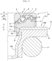
FIG. 2A is an enlarged vertical cross-sectional view of a main part, showing the strut bearing device, an upper insulator, and a coil spring. -
FIG. 2B is an enlarged view of a surrounded portion indicated by "a" inFIG. 2A . -
FIG. 3 is a perspective view seen from below, showing a state in which a lower case and an upper spring sheet are taken out and separated from each other. -
FIG. 4 is a front view showing a state in which the lower case and the upper spring sheet are taken out and separated from each other. -
FIG. 5 is a front view, similar toFIG. 4 , showing a modified example of an engagement projection and an engagement hole. -
FIG. 6 is a front view, similar toFIG. 4 , showing another modified example of the engagement projection and the engagement hole. -
FIG. 7A is an enlarged vertical cross-sectional view of a main part, similar toFIG. 2A , showing an example in which the engagement hole is replaced with an engagement recess. -
FIG. 7B is an enlarged view of a surrounded portion indicated by "b" inFIG. 7A . -
FIG. 8 is an enlarged vertical cross-sectional view of a main part, showing a modified example in which the engagement projection is provided in the upper spring sheet, and the engagement hole is provided in the lower case. - Hereinafter, embodiments of the present invention are described with reference to the drawings.
- In the description, a direction parallel to a rotation axis O (see
FIG. 1 ) of a strut bearing device 1 is referred to as an "axial direction" (see an arrow J inFIG. 1 , for example), a direction orthogonal to the rotation axis O is referred to as a "radial direction" (see an arrow R inFIG. 1 , for example), and views seen in the radial direction R (FIGS. 4 to 6 ) are set as front views. - In the description, a radial direction approaching the rotation axis O is referred to as a "radially inward direction" (see an arrow RI in
FIG. 1 , for example), and a radial direction going away from the rotation axis O is referred to as a "radially outward direction" (see an arrow RO inFIG. 1 , for example). When the rotation axis O is defined as a vertical direction, a horizontal direction that is orthogonal to the radial direction extending from the rotation axis O is referred to as a "circumferential direction" (see an arrow E inFIG. 3 , for example). - A vehicle strut suspension S shown in the schematic view with the partially cross-sectional view of
FIG. 1 is used in a state where anextendable strut 10 containing a shock absorber is fixed to an axle (not shown) and anupper mount 16 is fixed to the body of a vehicle. - The strut suspension S is provided with, at its upper portion, a strut bearing device 1 that is swingably rotated in proportion to a direction change of a steering wheel in accordance with steering operation, while supporting the vehicle body. A swing angle of the strut bearing 1 is defined so as to correspond to an allowable steering angle of a wheel, and is set in a range of 40° or more and 50° or less, for example.
- A
coil spring 11 serving as a suspension spring, and adust boot 12 used for protecting an oil seal of the shock absorber from foreign substances such as sand are provided on an outer-diameter side of thestrut 10 in the radially outward direction RO. The strut suspension S includes aspring support component 13 that supports an upper end of thecoil spring 11. Thespring support component 13 includes anupper spring sheet 14 and anupper insulator 15, as shown in the vertical cross-sectional view ofFIG. 2A . - As shown in the schematic view of
FIG. 1 , the vertical cross-sectional view ofFIG. 2A , the strut bearing device A includes a strut bearing 1 and anupper spring sheet 14 that is aspring support component 13 that supports the upper end of thecoil spring 11. - The strut bearing 1 includes an
upper case 2, alower case 3, anupper raceway ring 4, alower raceway ring 5, rollingelements 6, aretainer 7, an inner-diameter side seal 8, an outer-diameter side seal 9, and so on. - The
upper case 2 is fixed to an upper end portion of thestrut 10, and thelower case 3 receives theupper spring sheet 14 from above. Theupper raceway ring 4 is held by theupper case 2, and thelower raceway ring 5 is held by thelower case 3. The rollingelements 6 roll between theupper raceway ring 4 and thelower raceway ring 5, and theretainer 7 holds each of the rollingelements 6 so that theadjacent rolling elements 6 do not come into contact with each other. - The inner-
diameter side seal 8 is positioned in a radially inward direction RI relative to the rollingelements 6, and the outer-diameter side seal 9 is positioned in a radially outward direction RO relative to the rollingelements 6. - The
upper raceway ring 4, thelower raceway ring 5, and theupper spring sheet 14 are made of steel, and are formed in a manner that a steel plate is subjected to press working, and then undergoes quenching to be hardened. Theupper case 2 and thelower case 3 are made of a synthetic resin, and the inner-diameter side seal 8 and the outer-diameter side seal 9 are made of elastomer. - The synthetic resin used for the
upper case 2 and thelower case 3 is polyamide (PA66, PA46, PA612, PA6, PA9T, PA10T, and so on) and contains 20 to 60% by weight of glass fiber (GF) as reinforced fiber, for example. - The elastomer used for the inner-
diameter side seal 8 and the outer-diameter side seal 9 is thermoplastic elastomers (TPE) including TPS (styrene-based elastomer), TPO (olefin-based elastomer), TPU (urethane-based elastomer), TPA (amide-based elastomer), TPEE (ester-based elastomer), and so on. Rubber materials include nitrile rubber (NBR), hydrogenated nitrile rubber (HNBR), acrylic rubber (ACM), ethylene-acrylic rubber (AEM), fluorine rubber (FKM, FPM), silicone rubber (VQM), and so on. One of the rubber materials may be used, or two or more of the rubber materials may be suitably blended and used. - The
upper case 2 and thelower case 3 are molded through injection molding. Specifically, theupper case 2 is molded in a manner that a molten synthetic resin is injected, into a cavity for molding theupper case 2, through a gate of a mold having the cavity. Similarly, thelower case 3 is molded in a manner that the molten synthetic resin is injected, into a cavity for molding thelower case 3, through a gate of a mold having the cavity. - As shown in the vertical cross-sectional view of
FIG. 2A ,FIG. 2B that is the enlarged view of the surrounded portion "a" shown inFIG. 2A , the perspective view ofFIG. 3 , and the front view ofFIG. 4 , theupper spring sheet 14 has acylindrical part 14A and adisc part 14B extending in the radially outward direction RO from an upper end portion of thecylindrical part 14A. Thecylindrical part 14A has, at an upper part thereof, asquare hole 21 that penetrates in a radial direction R to serve as an engagement hole B. - The
lower case 3 has acylindrical member 17 fitted along an inner peripheral surface of the upper part of thecylindrical part 14A of theupper spring sheet 14. Thecylindrical member 17 has, at its outerperipheral surface 17A, a square-shapedprojection piece 18 serving as an engagement projection D that is to engage with thesquare hole 21 serving as the engagement hole B of theupper spring sheet 14. - A top face of the square-shaped
projection piece 18 is a substantially horizontal surface H1, and a bottom face of the square-shapedprojection piece 18 is an inclined surface F that reduces its diameter as approaching a lower side. As shown in the perspective view ofFIG. 3 and the front view ofFIG. 4 , theupper spring sheet 14 and thelower case 3 are brought close to each other, and the inclined surface F in the bottom face of the square-shapedprojection piece 18 serving as the engagement projection D in thelower case 3 made of a synthetic resin is fitted along from the upper part of the inner peripheral surface of thecylindrical part 14A of theupper spring sheet 14 made of the steel with elastically deforming thelower case 3, thereby easily lowering thelower case 3 down along theupper spring sheet 14. - Accordingly, as shown in the vertical cross-sectional views of
FIGS. 2A and2B , the square-shapedprojection piece 18 serving as the engagement projection D in thelower case 3 can be easily engaged with thesquare hole 21 serving as the engagement hole B of theupper spring sheet 14. As shown inFIGS. 2A and2B , relative movement of theupper spring sheet 14 and thelower case 3 in the axial direction J is restricted in the state where the square-shapedprojection piece 18 is engaged with thesquare hole 21. In addition, the top face that is the substantially horizontal surface H1 of the square-shapedprojection piece 18 is stopped at an upper wall K of thesquare hole 21. Therefore, separation between theupper spring sheet 14 serving as thespring support component 13 and thelower case 3 in the axial direction J can be surely prevented. - As shown in the vertical cross sectional view of
FIG. 2B , relationship among: a radial height G that is a projecting height of the square-shapedprojection piece 18 serving as the engagement projection D in the radially outward direction RO; a radial distance I from a distal end of the square-shapedprojection piece 18 to an outer peripheral surface of thecylindrical part 14A; and a thickness T of thecylindrical part 14A is expressed as G + I = T. When T is 2 mm, for example, the radial height G of the square-shapedprojection piece 18 should be around 0.5 to 1.0 mm, for example. - The square-shaped
projection piece 18 is engaged with thesquare hole 21 having a shape shown in the perspective view ofFIG. 3 and the front view ofFIG. 4 , in a state where the square-shapedprojection piece 18 of thelower case 3 is engaged with thesquare hole 21 of theupper spring sheet 14 as shown in the vertical cross-sectional views ofFIGS. 2A and2B . Therefore, the relative movement of theupper spring sheet 14 and thelower case 3 in the circumferential direction E shown inFIG. 3 is restricted. - An attachment position of the assembly of the strut bearing 1 and the
upper spring sheet 14 to a vehicle body in the circumferential direction E is fixed. Thus, thelower case 3 of the strut bearing 1 is restricted from moving relative to theupper spring sheet 14 in the circumferential direction E, as described above, in the strut bearing device A according to the embodiment of the present invention. - As described above, the
lower case 3 can be positioned relative to theupper spring sheet 14 in the circumferential direction E, so that theupper spring sheet 14 and thelower case 3 do not slide in the circumferential direction E. Therefore, a contact surface, with theupper spring sheet 14 made of steel, of thelower case 3 made of a synthetic resin is not worn away. - The engagement hole B of the
upper spring sheet 14 and the engagement projection D of thelower case 3 may respectively be along hole 22 and long-circle shapedprojection piece 19 as shown in the front view ofFIG. 5 , and may respectively be around hole 23 and a round shapedprojection piece 20 as shown in the front view ofFIG. 6 . The top face of the round shapedprojection piece 20 shown inFIG. 6 is not the substantially horizontal surface H1, but a side surface H2 of a column extending in the substantially horizontal direction. - As shown in the enlarged vertical cross-sectional view of a main part in
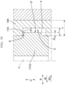
FIG. 7A andFIG. 7B that is the enlarged view of the surrounded portion "b" inFIG. 7A , thecylindrical part 14A of theupper spring sheet 14 may have an engagement recess C having a hollowed inner peripheral surface, instead of the engagement hole B. In such a configuration, the relative movement of theupper spring sheet 14 and thelower case 3 in the axial direction J and the circumferential direction E is also restricted in a state where the engagement projection D is engaged with the engagement recess C. The reference sign K inFIG. 7B indicates an upper wall of the engagement recess C. - As shown in the vertical cross-sectional view of
FIG. 7B , relationship among: the radial height G that is a projecting height of the engagement projection D in the radially outward direction RO; a radial depth L of the engagement recess C; and the thickness T of thecylindrical part 14A is expressed as G < L < T. When T is 2 mm, for example, L should be around 1.0 to 1.5 mm, for example, and G should be less than L, e.g., a level of 0.5 to 1.0 mm. If the outer peripheral surface of thecylindrical part 14A projects in the radially outward direction RO and the projecting part disadvantageously interferes with peripheral components, due to the engagement recess C that is provided in thecylindrical part 14A of theupper spring sheet 14, the engagement hole B penetrating in the radial direction R may be used instead of the engagement recess C. - It is merely required that at least a pair of the engagement hole B and the engagement projection D, or a pair of the engagement recess C and the engagement projection D, which are described above, is provided in the circumferential direction.
- As shown in the enlarged vertical cross-sectional view of the main part in
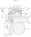
FIG. 8 , an engagement projection M projecting in the radially inward direction RI may be provided at the upper part of thecylindrical part 14A of theupper spring sheet 14, and an engagement hole N that is to engage with the engagement projection M and penetrates in the radial direction R may be provided in thecylindrical member 17 of thelower case 3. Even in such a configuration, the relative movement of theupper spring sheet 14 and thelower case 3 in the axial direction J and in the circumferential direction E is restricted in a state where the engagement projection M is engaged with the engagement hole N. The engagement recess having a hollowed outerperipheral surface 17A may be provided in thecylindrical body 17 of thelower case 3, so as to be engaged with the engagement projection M. - It is merely required that at least a pair of the engagement projection M and the engagement hole N, or a pair of the engagement projection M and the engagement recess, which are described above, is provided in the circumferential direction.
- The above description for the embodiments is all examples, and thus the present invention is not limited thereto. Various improvements and modifications can be applied without departing from the scope of the present invention.
Claims (4)
- A strut bearing device comprising:a strut bearing; andan upper spring sheet that is a spring support component supporting an upper end of a coil spring, whereinthe strut bearing includes:an upper case and a lower case;an upper raceway ring held by the upper case;a lower raceway ring held by the lower case; anda rolling element that rolls between the upper raceway ring and the lower raceway ring,the upper case and the lower case are made of a synthetic resin,the upper spring sheet is made of steel,the upper spring sheet has a cylindrical part and a disc part,the cylindrical part has, at an upper part thereof, one of an engagement hole penetrated in a radial direction and an engagement recess having a hollowed inner peripheral surface,the lower case has a cylindrical member fitted along an inner peripheral surface of the upper part of the cylindrical part,the cylindrical member has, at an outer peripheral surface thereof, an engagement projection engaged with the engagement hole or the engagement recess, andrelative movement of the upper spring sheet and the lower case in an axial direction and in a circumferential direction is restricted in a state where the engagement projection is engaged with the engagement hole or the engagement recess.
- The strut bearing device according to claim 1, whereinthe engagement projection of the lower case has a top face that is a substantially horizontal surface or a side face of a column extending in a substantially horizontal direction, andthe engagement projection has a bottom face that is an inclined face reducing a diameter thereof as approaching a lower side.
- A strut bearing device comprising:a strut bearing; andan upper spring sheet that is a spring support component supporting an upper end of a coil spring, whereinthe strut bearing includes:an upper case and a lower case;an upper raceway ring held by the upper case;a lower raceway ring held by the lower case; anda rolling element that rolls between the upper raceway ring and the lower raceway ring,the upper case and the lower case are made of a synthetic resin,the upper spring sheet is made of steel,the upper spring sheet has a cylindrical part and a disc part, andthe cylindrical part has, at an upper part thereof, an engagement projection that projects in a radially inward direction,the lower case has a cylindrical member fitted along an inner peripheral surface of the upper part of the cylindrical part,the cylindrical member has one of an engagement hole penetrated in a radial direction and an engagement recess that has a hollowed outer peripheral surface, the engagement hole and the engagement recess being engaged with the engagement projection, andrelative movement of the upper spring sheet and the lower case in an axial direction and in a circumferential direction is restricted in a state where the engagement hole or the engagement recess is engaged with the engagement projection.
- A vehicle strut suspension comprising the strut bearing device according to any one of claims 1 to 3.
Applications Claiming Priority (1)
| Application Number | Priority Date | Filing Date | Title |
|---|---|---|---|
| JP2021172904A JP7719443B2 (en) | 2021-10-22 | 2021-10-22 | Strut bearing device and strut suspension for vehicle |
Publications (1)
| Publication Number | Publication Date |
|---|---|
| EP4170192A1 true EP4170192A1 (en) | 2023-04-26 |
Family
ID=84358891
Family Applications (1)
| Application Number | Title | Priority Date | Filing Date |
|---|---|---|---|
| EP22202360.8A Pending EP4170192A1 (en) | 2021-10-22 | 2022-10-19 | Strut bearing device, and vehicle strut suspension |
Country Status (4)
| Country | Link |
|---|---|
| US (1) | US12031575B2 (en) |
| EP (1) | EP4170192A1 (en) |
| JP (1) | JP7719443B2 (en) |
| CN (1) | CN116006576B (en) |
Families Citing this family (3)
| Publication number | Priority date | Publication date | Assignee | Title |
|---|---|---|---|---|
| JP7512157B2 (en) * | 2020-10-01 | 2024-07-08 | 倉敷化工株式会社 | Suspension Mount |
| FR3125464B1 (en) * | 2021-07-23 | 2023-10-27 | Skf Svenska Kullagerfab Ab | Sealed suspension stop device |
| FR3127536B1 (en) * | 2021-09-30 | 2023-12-08 | Ntn Snr Roulements | SUSPENSION ROTATING STOP PROVIDED WITH A SHRINKED SEAL AND RETAINER |
Citations (5)
| Publication number | Priority date | Publication date | Assignee | Title |
|---|---|---|---|---|
| US6814496B2 (en) | 2001-03-21 | 2004-11-09 | Aktiebolaget Skf | Suspension thrust bearing with retaining means |
| JP2005201307A (en) * | 2004-01-14 | 2005-07-28 | Kayaba Ind Co Ltd | Spring seat |
| US20100014792A1 (en) * | 2008-07-17 | 2010-01-21 | Schaeffler Kg | Automotive strut ring bearing assembly with spring seat and integral dampening member |
| US8496383B2 (en) | 2008-09-26 | 2013-07-30 | Aktiebolaget Skf | Bump stop and associated MacPherson strut |
| KR20160059092A (en) * | 2014-11-17 | 2016-05-26 | 주식회사 베어링아트 | Strut bearing assembly |
Family Cites Families (8)
| Publication number | Priority date | Publication date | Assignee | Title |
|---|---|---|---|---|
| JP5489273B2 (en) | 2010-02-12 | 2014-05-14 | 河西工業株式会社 | Interior parts for vehicles |
| JP5906590B2 (en) * | 2011-06-09 | 2016-04-20 | オイレス工業株式会社 | Synthetic plastic plain bearing |
| JP5909976B2 (en) * | 2011-10-07 | 2016-04-27 | オイレス工業株式会社 | Synthetic plastic plain bearing |
| JP6194586B2 (en) * | 2013-01-29 | 2017-09-13 | オイレス工業株式会社 | Synthetic plastic plain bearing |
| KR101731527B1 (en) * | 2015-07-03 | 2017-05-02 | 주식회사 베어링아트 | Strut bearing assembly for vehicle |
| JP6211124B2 (en) * | 2016-03-30 | 2017-10-11 | オイレス工業株式会社 | Synthetic plastic plain bearing |
| JP6631648B2 (en) * | 2018-03-22 | 2020-01-15 | オイレス工業株式会社 | Slide bearing made of synthetic resin |
| DE102021205788A1 (en) * | 2021-06-08 | 2022-12-08 | Aktiebolaget Skf | floating bearing arrangement |
-
2021
- 2021-10-22 JP JP2021172904A patent/JP7719443B2/en active Active
-
2022
- 2022-10-04 US US17/937,904 patent/US12031575B2/en active Active
- 2022-10-18 CN CN202211273218.5A patent/CN116006576B/en active Active
- 2022-10-19 EP EP22202360.8A patent/EP4170192A1/en active Pending
Patent Citations (5)
| Publication number | Priority date | Publication date | Assignee | Title |
|---|---|---|---|---|
| US6814496B2 (en) | 2001-03-21 | 2004-11-09 | Aktiebolaget Skf | Suspension thrust bearing with retaining means |
| JP2005201307A (en) * | 2004-01-14 | 2005-07-28 | Kayaba Ind Co Ltd | Spring seat |
| US20100014792A1 (en) * | 2008-07-17 | 2010-01-21 | Schaeffler Kg | Automotive strut ring bearing assembly with spring seat and integral dampening member |
| US8496383B2 (en) | 2008-09-26 | 2013-07-30 | Aktiebolaget Skf | Bump stop and associated MacPherson strut |
| KR20160059092A (en) * | 2014-11-17 | 2016-05-26 | 주식회사 베어링아트 | Strut bearing assembly |
Also Published As
| Publication number | Publication date |
|---|---|
| US12031575B2 (en) | 2024-07-09 |
| JP7719443B2 (en) | 2025-08-06 |
| CN116006576A (en) | 2023-04-25 |
| JP2023062799A (en) | 2023-05-09 |
| CN116006576B (en) | 2026-05-08 |
| US20230128517A1 (en) | 2023-04-27 |
Similar Documents
| Publication | Publication Date | Title |
|---|---|---|
| US20230128517A1 (en) | Strut bearing device, and vehicle strut suspension | |
| US8496383B2 (en) | Bump stop and associated MacPherson strut | |
| KR101700924B1 (en) | Synthetic resin-made sliding bearing | |
| US9322435B2 (en) | Suspension thrust bearing device and suspension strut equipped with such a thrust bearing | |
| KR20210100003A (en) | Suspension thrust bearing device with pinched seal | |
| CN103003600B (en) | There is the axial thrust bearing device of seal ring | |
| US20170355241A1 (en) | Strut mount | |
| KR20210099997A (en) | Suspension thrust bearing device with blocked seal | |
| US11491839B2 (en) | Suspension thrust bearing device and suspension strut equiped with such a device | |
| US11396908B2 (en) | Suspension thrust bearing device and suspension strut equiped with such a device | |
| KR20240152226A (en) | Suspension bearing unit with gasket | |
| US20120020606A1 (en) | Cage for roller bearing | |
| CN113137429A (en) | Suspension thrust bearing device | |
| CN107131214B (en) | Bearing device for wheel | |
| JP2015014367A (en) | Rolling bearing device especially for steering columns | |
| JP2018123858A (en) | Ball joint and bearing sheet thereof | |
| US11493087B2 (en) | Strut bearing and vehicle strut suspension | |
| CN116104864A (en) | Thrust bearing arrangement and MacPherson suspension of the vehicle | |
| JP2024053432A (en) | Strut bearing device and strut suspension for vehicle | |
| JP7290832B2 (en) | Strut bearings and vehicle strut suspensions | |
| US12031583B2 (en) | Strut bearing device, vehicle strut suspension, producing method of lower case and seal of strut bearing device, and producing method of upper case and seal of strut bearing device | |
| WO2011026759A1 (en) | Bump stop device and macpherson strut | |
| US11833872B2 (en) | Suspension thrust bearing device with dust boot retainer | |
| JP2023085639A (en) | Strut bearings and vehicle strut suspensions | |
| KR20240152228A (en) | Suspension bearing unit with gasket |
Legal Events
| Date | Code | Title | Description |
|---|---|---|---|
| PUAI | Public reference made under article 153(3) epc to a published international application that has entered the european phase |
Free format text: ORIGINAL CODE: 0009012 |
|
| STAA | Information on the status of an ep patent application or granted ep patent |
Free format text: STATUS: THE APPLICATION HAS BEEN PUBLISHED |
|
| AK | Designated contracting states |
Kind code of ref document: A1 Designated state(s): AL AT BE BG CH CY CZ DE DK EE ES FI FR GB GR HR HU IE IS IT LI LT LU LV MC ME MK MT NL NO PL PT RO RS SE SI SK SM TR |
|
| STAA | Information on the status of an ep patent application or granted ep patent |
Free format text: STATUS: REQUEST FOR EXAMINATION WAS MADE |
|
| 17P | Request for examination filed |
Effective date: 20231026 |
|
| RBV | Designated contracting states (corrected) |
Designated state(s): AL AT BE BG CH CY CZ DE DK EE ES FI FR GB GR HR HU IE IS IT LI LT LU LV MC ME MK MT NL NO PL PT RO RS SE SI SK SM TR |
|
| STAA | Information on the status of an ep patent application or granted ep patent |
Free format text: STATUS: EXAMINATION IS IN PROGRESS |
|
| 17Q | First examination report despatched |
Effective date: 20250806 |