EP4170186A1 - Compressor, in particular radial compressor - Google Patents
Compressor, in particular radial compressor Download PDFInfo
- Publication number
- EP4170186A1 EP4170186A1 EP21203945.7A EP21203945A EP4170186A1 EP 4170186 A1 EP4170186 A1 EP 4170186A1 EP 21203945 A EP21203945 A EP 21203945A EP 4170186 A1 EP4170186 A1 EP 4170186A1
- Authority
- EP
- European Patent Office
- Prior art keywords
- compressor
- liquid
- impeller
- injected
- injection
- Prior art date
- Legal status (The legal status is an assumption and is not a legal conclusion. Google has not performed a legal analysis and makes no representation as to the accuracy of the status listed.)
- Withdrawn
Links
- 239000007788 liquid Substances 0.000 claims abstract description 45
- 238000002347 injection Methods 0.000 claims abstract description 40
- 239000007924 injection Substances 0.000 claims abstract description 40
- 238000007906 compression Methods 0.000 claims abstract description 24
- 239000012530 fluid Substances 0.000 claims abstract description 22
- 230000006835 compression Effects 0.000 claims abstract description 18
- 238000000034 method Methods 0.000 claims abstract description 18
- XLYOFNOQVPJJNP-UHFFFAOYSA-N water Substances O XLYOFNOQVPJJNP-UHFFFAOYSA-N 0.000 claims description 15
- OKKJLVBELUTLKV-UHFFFAOYSA-N Methanol Chemical compound OC OKKJLVBELUTLKV-UHFFFAOYSA-N 0.000 claims description 9
- 238000001704 evaporation Methods 0.000 claims description 9
- 230000008020 evaporation Effects 0.000 claims description 9
- 239000000203 mixture Substances 0.000 claims description 8
- LFQSCWFLJHTTHZ-UHFFFAOYSA-N Ethanol Chemical compound CCO LFQSCWFLJHTTHZ-UHFFFAOYSA-N 0.000 claims description 7
- 230000001105 regulatory effect Effects 0.000 claims description 3
- 238000009835 boiling Methods 0.000 description 5
- 238000011161 development Methods 0.000 description 5
- 230000018109 developmental process Effects 0.000 description 5
- 238000002156 mixing Methods 0.000 description 5
- 238000009834 vaporization Methods 0.000 description 4
- 230000008016 vaporization Effects 0.000 description 4
- 238000001816 cooling Methods 0.000 description 3
- 230000001419 dependent effect Effects 0.000 description 2
- 230000000694 effects Effects 0.000 description 2
- 238000009825 accumulation Methods 0.000 description 1
- 238000007792 addition Methods 0.000 description 1
- 230000009286 beneficial effect Effects 0.000 description 1
- 230000000052 comparative effect Effects 0.000 description 1
- 230000003628 erosive effect Effects 0.000 description 1
- 230000014509 gene expression Effects 0.000 description 1
- 230000003116 impacting effect Effects 0.000 description 1
- 238000005381 potential energy Methods 0.000 description 1
Images
Classifications
-
- F—MECHANICAL ENGINEERING; LIGHTING; HEATING; WEAPONS; BLASTING
- F04—POSITIVE - DISPLACEMENT MACHINES FOR LIQUIDS; PUMPS FOR LIQUIDS OR ELASTIC FLUIDS
- F04D—NON-POSITIVE-DISPLACEMENT PUMPS
- F04D29/00—Details, component parts, or accessories
- F04D29/40—Casings; Connections of working fluid
- F04D29/42—Casings; Connections of working fluid for radial or helico-centrifugal pumps
- F04D29/4206—Casings; Connections of working fluid for radial or helico-centrifugal pumps especially adapted for elastic fluid pumps
- F04D29/4213—Casings; Connections of working fluid for radial or helico-centrifugal pumps especially adapted for elastic fluid pumps suction ports
-
- F—MECHANICAL ENGINEERING; LIGHTING; HEATING; WEAPONS; BLASTING
- F04—POSITIVE - DISPLACEMENT MACHINES FOR LIQUIDS; PUMPS FOR LIQUIDS OR ELASTIC FLUIDS
- F04D—NON-POSITIVE-DISPLACEMENT PUMPS
- F04D17/00—Radial-flow pumps, e.g. centrifugal pumps; Helico-centrifugal pumps
- F04D17/08—Centrifugal pumps
- F04D17/10—Centrifugal pumps for compressing or evacuating
-
- F—MECHANICAL ENGINEERING; LIGHTING; HEATING; WEAPONS; BLASTING
- F04—POSITIVE - DISPLACEMENT MACHINES FOR LIQUIDS; PUMPS FOR LIQUIDS OR ELASTIC FLUIDS
- F04D—NON-POSITIVE-DISPLACEMENT PUMPS
- F04D29/00—Details, component parts, or accessories
- F04D29/58—Cooling; Heating; Diminishing heat transfer
- F04D29/582—Cooling; Heating; Diminishing heat transfer specially adapted for elastic fluid pumps
- F04D29/5846—Cooling; Heating; Diminishing heat transfer specially adapted for elastic fluid pumps cooling by injection
-
- F—MECHANICAL ENGINEERING; LIGHTING; HEATING; WEAPONS; BLASTING
- F04—POSITIVE - DISPLACEMENT MACHINES FOR LIQUIDS; PUMPS FOR LIQUIDS OR ELASTIC FLUIDS
- F04D—NON-POSITIVE-DISPLACEMENT PUMPS
- F04D29/00—Details, component parts, or accessories
- F04D29/70—Suction grids; Strainers; Dust separation; Cleaning
- F04D29/701—Suction grids; Strainers; Dust separation; Cleaning especially adapted for elastic fluid pumps
- F04D29/705—Adding liquids
Definitions
- the invention relates to a compressor, in particular a centrifugal compressor.
- water injection is used in raw gas compressors, where the water is injected between the compressor stages in order to reduce the outlet temperature of the medium between the individual stages in order to prevent polymerisation of the medium.
- the limiting degree of vaporization of the liquid injected into the compressor gas stream is problematic. If the liquid is injected into a low velocity area of the compressor, breaking up or atomizing the liquid into very small droplets may not be achieved. Very small droplets are necessary to achieve a high degree of vaporization, because the surface area of such a droplet is large in relation to the volume of the droplet and so the droplet can easily absorb heat and vaporize.
- the object of the invention is to specify an improved compressor, in particular a radial compressor.
- a compressor comprising a rotor which extends along an axis of rotation, a housing, the housing being arranged around the rotor, the housing having an axial inflow and downstream of the axial inflow a first compression stage and further downstream of the first Compression stage having a first radial outflow for a process fluid, the first radial outflow leading through the inner housing, further an impeller, which is arranged on the rotor, with an injection device for injecting a liquid into the axial inflow.
- compression stage means the compression of a specific mass flow by means of one or more compressor impellers.
- compression stage or “compression stage” according to the invention is the compression taking place in an uninterrupted flow path in the compressor, without the mass flow to be compressed or a partial flow thereof being derived from the compressor and possibly being subjected to other process steps.
- a mixture is used as the liquid.
- a further improvement consists in using suitable mixing partners to produce a higher boiling temperature if this is beneficial to the compression process.
- mixing could take place within the medium to be compressed if the enthalpy of mixing is negative and additional (mixing) cooling is to be achieved.
- the aim of the invention is also to approach isothermal compression, which leads to a high level of efficiency.
- the volume flow of the flow can be reduced. With a given cross-section, the speed and the flow losses decrease.
- injection in the spiral stage (last stage of a process stage) is particularly effective.
- an injection device is also proposed in inlets and return stages.
- the amount of liquid should be regulated to ensure an optimal condition close to saturation and to avoid liquid accumulation.
- the amount of water is around 2% by weight.
- the total volume flow including evaporated, added water is reduced by about 8%, which should reduce the losses of a diffuser and a spiral by about 15%.
- Either a gas in liquid aggregate state can be injected or another medium such as water, methanol or ethanol, or a mixture of several components.
- the injected medium is selected so that its evaporation temperature is lower than the temperature at the impeller outlet of the subsequent compression stage without liquid injection, based on the final pressure there.
- the evaporation temperature in the case of mixtures: the lowest-boiling component
- the gas temperature at the point of injection can be lower than the gas temperature at the point of injection.
- the injected medium is chosen so that the evaporation temperature is above the temperature of the compressed gas at the point of injection and below the temperature after of the subsequent compressor stage, based on the case without liquid injection.
- Active dosing of the amount of liquid improves liquid injection.
- the amount of liquid is calculated using the temperature and the relative humidity of the sucked-in medium.
- the dosing can then be done by switching nozzles on and off or via the pump speed or via a by-pass control.
- the dwell time with injected liquid plays a crucial role in the effective humidification of the process fluid.
- a minimum distance between an injection and an impeller inlet of 3 times the impeller inlet diameter is proposed in order to achieve an effective reduction in the compressor drive power by means of liquid injection.
- the distance between the injection and the impeller inlet is essentially 10 times the impeller inlet diameter.
- the relationship applies that the distance between the injection and the impeller inlet can be smaller, the finer the liquid droplets that are introduced.
- cascading of the injection into a plurality of units with a defined distance from one another is proposed. Again should the minimum distance of the last cascade must not be fallen below.
- the injection nozzles in the cascade can be offset from one another, viewed in the direction of flow, in order not to interfere with one another. In a cascaded arrangement, the amount of liquid injected per position can be reduced.
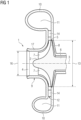
- FIG 1 shows a known radial flow machine in a (simplified) sectional view.
- the flow machine shown is a compressor 1, in particular a centrifugal compressor.
- the turbomachine includes, among other things, a radial impeller 2 which is mounted such that it can rotate about an axis of rotation 3 .
- the impeller 2 has an axial inflow 4 and a radial outflow 5 .
- the impeller 2 comprises a hub 6 and impeller blades 7 protruding radially from the hub 6. Flow channels through which a fluid can flow are formed between the impeller blades 7. Furthermore, the hub 6 is connected to a shaft of the compressor 1 that is not shown in the figure.
- the impeller 2 has a wheel disc 8 which is formed in one piece with the hub 6 and connects the impeller blades 7 to one another.
- the impeller 2 is a so-called open impeller, ie an impeller without a cover disk.
- the impeller 2 could be a so-called closed impeller, ie an impeller with a cover disk.
- the compressor 1 comprises a housing 9 in which the impeller 2 is placed.
- a part of the housing 9 is designed as a spiral housing. That is, the housing 9 has a spiral housing part 10 with a spiral cavity 11 .
- the compressor has an annular diffuser 12 which is axially symmetrical with respect to the axis of rotation 3 is designed as a hollow chamber or as a channel in the housing 9 .
- the diffuser 12 is arranged around a circumference of the impeller 2 and is designed as a radial diffuser.
- the diffuser 12 opens into the spiral housing part 10 or into its cavity 11.
- an outlet diameter 13 of the impeller 2 is indicated in the form of a double arrow.
- the diffuser 12 has a plurality of diffuser vanes 14 . That is, diffuser 12 is a vaned diffuser. In the present exemplary embodiment, the diffuser 12 has six diffuser vanes 14, of which FIG 1 only two are visible. In principle, however, the diffuser 12 could also have a different number of diffuser vanes 14 .
- the compressor 1 is used to compress a fluid such as air.
- a fluid such as air.
- the fluid flows axially through the axial inflow 4 into the impeller 2 or into the flow channels formed by the impeller blades 7.
- the fluid is set in rotation by the impeller 2 and leaves the impeller 2 radially outwards through the radial outflow 5.
- the diffuser 12 converts part of the kinetic energy of the fluid into potential energy in the form of pressure and guides the fluid into the cavity 11 of the volute casing part 10.
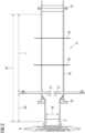
- the figure 2 shows a longitudinal section of a schematic representation of a part of the compressor 1 with an injection device 15 according to the invention figure 2 part of the axial inflow 4 can be seen.
- the double arrow is an impeller inlet diameter 16.
- the impeller inlet 17 is before the in figure 2 not shown impeller 2 arranged.
- An inflow housing 18 is arranged at the impeller inlet 17 and is connected to one another via a plurality of flanges 19 .
- a nozzle 21 is arranged in the inflow housing 18 at a distance 20 .
- the nozzle 21 is designed to supply liquid.
- a process fluid flowing from the right is moved in the direction of the compressor 1 and a liquid gets into the process fluid by means of the nozzles 21 .
- the evaporation temperature of the liquid is lower than the temperature of the process fluid to be compressed after injection in the compression process.
- the injection device 15 has a control device, not shown in detail, which is designed in such a way that the quantity of injected liquid can be controlled.
- the injection device 15 is designed in such a way that the process fluid to be compressed is first sucked in and the quantity of injected liquid depends on the temperature and relative humidity of the sucked-in process fluid.
- the injection device 15 is designed in such a way that the liquid is injected within the process fluid to be compressed.
- the injection device 15 can have a plurality of nozzles 21 (not shown) which are arranged one behind the other in the direction of flow of the process fluid.
- the injection effect is advantageous if the distance 20 between the last nozzle 21 in front of the impeller 2 and the impeller inlet 17 is three times the impeller inlet diameter 16 .
- a further advantageous effect is seen when the distance 20 between the last nozzle 21 in front of the impeller 2 and the impeller inlet 17 is 0.5 to 0.75 times, preferably 0.66 times, the impeller inlet diameter 16 .
- the injection device 15 is particularly effective when the distance 20 between the last nozzle 21 in front of the impeller 2 and the impeller inlet 17 is 10 times the impeller inlet diameter 16 .
- a further possibility of improving the effectiveness of the injection device 15 is achieved by arranging a plurality of nozzles one behind the other in the direction of flow. Improved mixing is possible as a result.
- this improved arrangement is shown schematically by a first line 23 and a second line 24.
- Further nozzles are arranged both on the first line 23 and on the second line 24 .
- the distance between the nozzles 21 and the position that corresponds to 10 times the distance 22 is the length L.
- the distance between the nozzle 21 and the further nozzle at the position on the first line 23 corresponds essentially to one third of the length L .
- the distance between the further nozzles at the first position 23 and the further nozzles at the position on the second line 24 corresponds essentially to one third of the length L.
- the distance between the further nozzles at the second position 24 and the position corresponding to 10 times the distance 22 is essentially one third of the length L.
Abstract
Verdichter (1) umfassend einen Rotor, der sich entlang einer Rotationsachse (3) erstreckt, ein Gehäuse (9), wobei das Gehäuse (9) um den Rotor angeordnet ist, wobei das Gehäuse (9) eine axiale Zuströmung (4) und stromabwärts der axialen Zuströmung (4) eine erste Verdichtungsstufe und weiter stromabwärts der ersten Verdichtungsstufe eine radiale Abströmung (5) für ein Prozessfluid aufweist, wobei die radiale Abströmung (5) durch das Gehäuse (9) führt, ferner ein Laufrad (2), das auf dem Rotor angeordnet ist, mit einer Einspritzvorrichtung (15) zur Einspritzung einer Flüssigkeit in die axiale Zuströmung (4).Compressor (1) comprising a rotor extending along an axis of rotation (3), a casing (9), the casing (9) being arranged around the rotor, the casing (9) having an axial inflow (4) and downstream the axial inflow (4) has a first compression stage and further downstream of the first compression stage a radial outflow (5) for a process fluid, the radial outflow (5) leading through the housing (9), furthermore an impeller (2) which is is arranged on the rotor, with an injection device (15) for injecting a liquid into the axial inflow (4).
Description
Die Erfindung betrifft einen Verdichter, insbesondere einen Radialverdichter.The invention relates to a compressor, in particular a centrifugal compressor.
In heutigen Verdichtern, insbesondere Radialverdichtern werden Stufenwirkungsgrade von etwa 90% erreicht, was als physikalische Grenze angesehen wird. Es ist möglich den Wirkungsgrad zu erhöhen, indem eine Wassereinspritzung verwendet wird. Die Vorteile der Wassereinspritzung wurden bereits bei Gasturbinen erkannt, wo die Wassereinspritzung einen wesentlichen Beitrag zur Steigerung der Leistung und des Wirkungsgrades beiträgt. Bei der Wassereinspritzung wird Wasser mit hohem Druck vor dem Verdichter oder zwischen den Stufen bei mehrstufigen Verdichtern eingespritzt. Das Wasser verdunstet während der Verdichtung und kühlt kontinuierlich das Gas, wie in dem Vergleichsprozess der isothermen Verdichtung. Dadurch kann der Wirkungsgrad um 1-2% gesteigert werden.Stage efficiencies of around 90% are achieved in today's compressors, in particular centrifugal compressors, which is regarded as the physical limit. It is possible to increase efficiency by using water injection. The advantages of water injection have already been recognized in gas turbines, where water injection makes a significant contribution to increasing performance and efficiency. With water injection, water is injected at high pressure before the compressor or between the stages in multi-stage compressors. The water evaporates during compression and continuously cools the gas, as in the comparative isothermal compression process. As a result, the efficiency can be increased by 1-2%.
Im Bereich der Verdichtertechnologie wird die Wassereinspritzung in Rohgasverdichtern eingesetzt, wo das Wasser zwischen den Verdichterstufen eingespritzt wird, um die Austrittstemperatur des Mediums zwischen den einzelnen Stufen zu reduzieren, um eine Polymerisation des Mediums zu verhindern.In the field of compressor technology, water injection is used in raw gas compressors, where the water is injected between the compressor stages in order to reduce the outlet temperature of the medium between the individual stages in order to prevent polymerisation of the medium.
Obwohl die Vorteile, die durch das Einspritzen von verdampfbarer Flüssigkeit direkt in den Gasstrom eines Verdichters bekannt sind, sind allerdings auch einige Nachteile bekannt.While the benefits of injecting vaporizable liquid directly into the gas stream of a compressor are well known, some disadvantages are also well known.
Problematisch ist der begrenzende Grad an Verdampfung der in den Verdichtergasstrom eingespritzten Flüssigkeit erzielt wird. Wenn die Flüssigkeit in ein Gebiet niedriger Geschwindigkeit des Verdichters eingespritzt wird, kann es sein, dass das Aufbrechen oder Zerstäuben der Flüssigkeit in sehr kleine Tröpfchen nicht erreicht wird. Sehr kleine Tröpfchen sind notwendig, um einen hohen Grad an Verdampfung zu erzielen, weil der Oberflächeninhalt eines solchen Tröpfchens in Bezug auf das Volumen des Tröpfchens groß ist und das Tröpfchen so leicht Wärme absorbieren und verdampfen kann.The limiting degree of vaporization of the liquid injected into the compressor gas stream is problematic. If the liquid is injected into a low velocity area of the compressor, breaking up or atomizing the liquid into very small droplets may not be achieved. Very small droplets are necessary to achieve a high degree of vaporization, because the surface area of such a droplet is large in relation to the volume of the droplet and so the droplet can easily absorb heat and vaporize.
Große Flüssigkeitströpfchen, die auf innere Verdichterteile, wie das Laufrad, auftreffen, führen zu der Gefahr einer starken Erosion.Large liquid droplets impacting internal compressor parts such as the impeller create the risk of severe erosion.
Aufgabe der Erfindung ist es, einen verbesserten Verdichter, insbesondere Radialverdichter anzugeben.The object of the invention is to specify an improved compressor, in particular a radial compressor.
Diese Aufgabe wird erfindungsgemäß gelöst durch einen Verdichter umfassend einen Rotor, der sich entlang einer Rotationsachse erstreckt, ein Gehäuse, wobei das Gehäuse um den Rotor angeordnet ist, wobei das Gehäuse eine axiale Zuströmung und stromabwärts der axialen Zuströmung eine erste Verdichtungsstufe und weiter stromabwärts der ersten Verdichtungsstufe eine erste radiale Abströmung für ein Prozessfluid aufweist, wobei die erste radiale Abströmung durch das Innengehäuse führt, ferner ein Laufrad, das auf dem Rotor angeordnet ist, mit einer Einspritzvorrichtung zur Einspritzung einer Flüssigkeit in die axiale Zuströmung.This object is achieved according to the invention by a compressor comprising a rotor which extends along an axis of rotation, a housing, the housing being arranged around the rotor, the housing having an axial inflow and downstream of the axial inflow a first compression stage and further downstream of the first Compression stage having a first radial outflow for a process fluid, the first radial outflow leading through the inner housing, further an impeller, which is arranged on the rotor, with an injection device for injecting a liquid into the axial inflow.
Die von dem Hauptanspruch abhängigen Unteransprüche beinhalten vorteilhafte Weiterbildungen der Erfindung.The dependent claims dependent on the main claim contain advantageous developments of the invention.
Im Zusammenhang mit der Erfindung bedeuten Ausdrücke wie axial, radial, tangential oder Umfangsrichtung jeweils einen Bezug zu der Achse des Rotors bzw. der Rotationsachse. Eine Verdichtungsstufe bedeutet hierbei die Verdichtung eines bestimmten Massenstroms mittels eines oder mehrerer Verdichterlaufräder. Entscheidend bei dem erfindungsgemäßen Gebrauch des Begriffs "Verdichterstufe" oder "Verdichtungsstufe" ist die in einem ununterbrochenen Strömungspfad in dem Verdichter stattfindende Verdichtung, ohne, dass der zu verdichtende Massenstrom oder ein Teilstrom davon aus dem Verdichter abgeleitet wird und ggf. anderen Prozessschritten unterzogen wird. Dies bedeutet auch, dass eingangs einer Verdichtungsstufe das zu verdichtende Prozessfluid mittels einer Einströmung in das Gehäuse des Verdichters eingeleitet wird und ausgangs einer Verdichtungsstufe zumindest ein Teil - in der Regel der gesamte Massenstrom des Prozessfluids - wieder aus dem Gehäuse der entsprechenden Verdichtungsstufe mittels einer Abströmung ausgeleitet wird.In connection with the invention, expressions such as axial, radial, tangential or circumferential direction each mean a reference to the axis of the rotor or the axis of rotation. A compression stage here means the compression of a specific mass flow by means of one or more compressor impellers. The decisive factor in the use of the term "compression stage" or "compression stage" according to the invention is the compression taking place in an uninterrupted flow path in the compressor, without the mass flow to be compressed or a partial flow thereof being derived from the compressor and possibly being subjected to other process steps. This also means that at the beginning of a compression stage the process fluid to be compressed is introduced into the housing of the compressor by means of an inflow and at least part - usually the entire mass flow of the process fluid - is discharged out of the housing of the corresponding compression stage again by means of an outflow at the outlet of a compression stage.
Erfindungsgemäß wird ein Gemisch als Flüssigkeit verwendet.According to the invention, a mixture is used as the liquid.
Durch die Beimischung von Methanol (Siedepunkt 65°C) oder Ethanol (Siedepunkt 78°C) kann eine zielgenaue Verdunstung im Verdichtungsprozess eingestellt werden. Entlang der Verdichtungsstrecke werden mit der Temperaturerhöhung verschiedene Anteile des Gemisches verdunsten und Wärme aufnehmen. Dadurch kann eine niedrigere Temperatur erzielt werden, als wenn man nur mit einer einphasigen Flüssigkeit arbeitet.By adding methanol (boiling point 65°C) or ethanol (boiling point 78°C), targeted evaporation can be set in the compression process. Along the compression section, various parts of the mixture will evaporate and absorb heat as the temperature increases. This allows a lower temperature to be achieved than when working with only a single-phase liquid.
Eine weitere Verbesserung besteht darin, eine höhere Siedetemperatur durch geeignete Mischungspartner herzustellen, wenn es dem Verdichtungsprozess zuträglich ist. Außerdem könnte das Mischen innerhalb des zu verdichtenden Mediums erfolgen, wenn die Mischungsenthalpie negativ ist und eine zusätzliche (Mischungs-)Kühlung erzielt werden soll.A further improvement consists in using suitable mixing partners to produce a higher boiling temperature if this is beneficial to the compression process. In addition, mixing could take place within the medium to be compressed if the enthalpy of mixing is negative and additional (mixing) cooling is to be achieved.
Mit der Erfindung wird zudem das Ziel verfolgt, sich an eine isotherme Verdichtung anzunähern, die zu einem hohen Wirkungsgrad führt.The aim of the invention is also to approach isothermal compression, which leads to a high level of efficiency.
Mit der erfindungsgemäßen Verdampfung einer Flüssigkeit, wie z.B. Wasser oder Flüssiggas, kann der Volumenstrom der Strömung reduziert werden. Bei einem gegebenen Querschnitt sinken damit die Geschwindigkeit und die Strömungsverluste.With the evaporation of a liquid according to the invention, such as water or liquid gas, the volume flow of the flow can be reduced. With a given cross-section, the speed and the flow losses decrease.
Somit kann die Verdampfung dazu genutzt werden, Verdichter kompakter auszulegen, ohne der negativen Folgen der Kompaktheit auf die Leistung des Verdichters.Thus, evaporation can be used to make compressors more compact without the negative consequences of compactness on the performance of the compressor.
In einer vorteilhaften Weiterbildung ist eine Einspritzung in der Spiralstufe (letzte Stufe einer Prozessstufe) besonders wirkungsvoll.In an advantageous development, injection in the spiral stage (last stage of a process stage) is particularly effective.
In weiteren vorteilhaften Weiterbildungen wird eine Einspritzvorrichtung auch in Einläufen und Rückführstufen vorgeschlagen. In Abhängigkeit vom Betriebspunkt sollte die Menge der Flüssigkeit geregelt werden, um einen optimalen Zustand nahe der Sättigung sicherzustellen und Flüssigkeitsansammlung zu vermeiden.In further advantageous developments, an injection device is also proposed in inlets and return stages. Depending on the operating point, the amount of liquid should be regulated to ensure an optimal condition close to saturation and to avoid liquid accumulation.
In einer vorteilhaften Weiterbildung liegt die Menge des Wassers etwa bei 2 Gew.-%. Hierbei reduziert sich der Gesamtvolumenstrom inkl. Verdampftem, zugefügtem Wasser um etwa 8% was die Verluste eines Diffusors und einer Spirale um etwa 15% reduzieren sollte.In an advantageous development, the amount of water is around 2% by weight. Here, the total volume flow including evaporated, added water is reduced by about 8%, which should reduce the losses of a diffuser and a spiral by about 15%.
Es kann entweder ein Gas in flüssigem Aggregatzustand eingespritzt werden oder ein anderes Medium wie z.B. Wasser, Methanol oder Ethanol, oder ein Gemisch aus mehreren Komponenten.Either a gas in liquid aggregate state can be injected or another medium such as water, methanol or ethanol, or a mixture of several components.
Das eingespritzte Medium wird so ausgewählt, dass seine Verdampfungstemperatur niedriger liegt als die Temperatur am Laufradaustritt der nachfolgenden Verdichtungsstufe ohne Flüssigkeitseinspritzung, bezogen auf den dort vorliegenden Enddruck.The injected medium is selected so that its evaporation temperature is lower than the temperature at the impeller outlet of the subsequent compression stage without liquid injection, based on the final pressure there.
Bei einem Gemisch mehrerer Flüssigkeiten muss diese Bedingung, für die am höchsten siedenden Komponente erfüllt sein. Andererseits kann die Verdampfungstemperatur (bei Gemischen: der am niedrigsten siedenden Komponente) niedriger sein als die Gastemperatur an der Einspritzstelle.In the case of a mixture of several liquids, this condition must be met for the component with the highest boiling point. On the other hand, the evaporation temperature (in the case of mixtures: the lowest-boiling component) can be lower than the gas temperature at the point of injection.
Das eingespritzte Medium wird so gewählt, dass die Verdampfungstemperatur über der Temperatur des verdichteten Gases an der Einspritzstelle liegt und unterhalb der Temperatur nach der nachfolgenden Verdichterstufe, bezogen auf den Fall ohne Flüssigkeitseinspritzung.The injected medium is chosen so that the evaporation temperature is above the temperature of the compressed gas at the point of injection and below the temperature after of the subsequent compressor stage, based on the case without liquid injection.
Eine sehr gute interne Kühlung ist erreicht, wenn die Temperatur nach dem der Einspritzung folgenden Verdichtungsprozess über der Verdampfungstemperatur der Flüssigkeit liegt, bei Flüssigkeitsgemischen über der höchsten Verdampfungstemperatur der Einzelkomponenten. Für diesen Fall würde das Potenzial der inneren Kühlung ausgenutzt werden, da die hohe Enthalpie des Verdampfungsprozesses ausgenutzt wurde.A very good internal cooling is achieved when the temperature after the compression process following the injection is above the vaporization temperature of the liquid, in the case of liquid mixtures above the highest vaporization temperature of the individual components. In this case, the potential of internal cooling would be exploited, since the high enthalpy of the evaporation process was exploited.
Durch eine aktive Dosierung der Flüssigkeitsmenge, wird die Flüssigkeitseinspritzung verbessert. Die Berechnung der Flüssigkeitsmenge erfolgt über die Temperatur und die relative Feuchte des angesaugten Mediums. Die Dosierung kann dann durch Zu- und Abschaltung von Düsen oder über die Pumpendrehzahl oder auch über eine By-Pass Regelung erfolgen.Active dosing of the amount of liquid improves liquid injection. The amount of liquid is calculated using the temperature and the relative humidity of the sucked-in medium. The dosing can then be done by switching nozzles on and off or via the pump speed or via a by-pass control.
Eine entscheidende Rolle spielt die Verweilzeit mit eingespritzter Flüssigkeit für die effektive Befeuchtung des Prozessfluids.The dwell time with injected liquid plays a crucial role in the effective humidification of the process fluid.
Erfindungsgemäß wird ein Mindestabstand zwischen einer Eindüsung und einem Laufradeintritt vom 3-fachem des Laufradeintrittsdurchmessers vorgeschlagen, um mittels Flüssigkeitseinspritzung eine effektive Reduzierung der Verdichterantriebsleistung zu erreichen.According to the invention, a minimum distance between an injection and an impeller inlet of 3 times the impeller inlet diameter is proposed in order to achieve an effective reduction in the compressor drive power by means of liquid injection.
Es hat sich gezeigt, dass ein Optimum erreichbar ist, wenn der Abstand zwischen Eindüsung und Laufradeintritt im Wesentlichen beim 10-fachen des Laufradeintrittsdurchmessers liegt. Generell gilt der Zusammenhang, dass der Abstand der Eindüsung zum Laufradeintritt umso geringer sein kann, je feiner die eingebrachten Flüssigkeitströpfchen sind.It has been shown that an optimum can be achieved if the distance between the injection and the impeller inlet is essentially 10 times the impeller inlet diameter. In general, the relationship applies that the distance between the injection and the impeller inlet can be smaller, the finer the liquid droplets that are introduced.
In einer weiteren vorteilhaften Weiterbildung wird eine Kaskadierung der Einspritzung in mehreren Einheiten mit definiertem Abstand zueinander vorgeschlagen. Auch hier sollte der Mindestabstand der letzten Kaskade nicht unterschritten werden. Die Einspritzdüsen in der Kaskade können mit Blick in Strömungsrichtung versetzt zueinander angeordnet werden, um sich gegenseitig nicht zu stören. In kaskadierter Anordnung kann die eingespritzte Flüssigkeitsmenge pro Position reduziert werden.In a further advantageous development, cascading of the injection into a plurality of units with a defined distance from one another is proposed. Again should the minimum distance of the last cascade must not be fallen below. The injection nozzles in the cascade can be offset from one another, viewed in the direction of flow, in order not to interfere with one another. In a cascaded arrangement, the amount of liquid injected per position can be reduced.
Im Folgenden ist die Erfindung anhand spezieller Ausführungsbeispiele unter Bezugnahme auf Zeichnungen näher erläutert.The invention is explained in more detail below using specific exemplary embodiments with reference to drawings.
Die oben beschriebenen Eigenschaften, Merkmale und Vorteile dieser Erfindung sowie die Art und Weise, wie diese erreicht werden, werden klarer und deutlicher verständlich im Zusammenhang mit der folgenden Beschreibung der Ausführungsbeispiele, die im Zusammenhang mit den Zeichnungen näher erläutert werden.The properties, features and advantages of this invention described above, and the manner in which they are achieved, will become clearer and more clearly understood in connection with the following description of the exemplary embodiments, which are explained in more detail in connection with the drawings.
Gleiche Bauteile oder Bauteile mit gleicher Funktion sind dabei mit gleichen Bezugszeichen gekennzeichnet.Identical components or components with the same function are identified with the same reference symbols.
Ausführungsbeispiele der Erfindung werden nachfolgend anhand der Zeichnungen beschrieben. Diese sollen die Ausführungsbeispiele nicht maßstäblich darstellen, vielmehr ist die Zeichnung, wo zur Erläuterung dienlich, in schematisierter und/oder leicht verzerrter Form ausgeführt. Im Hinblick auf Ergänzungen der in der Zeichnung unmittelbar erkennbaren Lehren wird auf den einschlägigen Stand der Technik verwiesen.Exemplary embodiments of the invention are described below with reference to the drawings. These are not intended to represent the exemplary embodiments to scale, rather the drawing, where useful for explanation, is in schematic and/or slightly distorted form. With regard to additions to the teachings that can be seen directly in the drawing, reference is made to the relevant state of the art.
Es zeigen:
Figur 1- einen Schnittdarstellung eines Radialverdichters gemäß dem Stand der Technik
Figur 2- einen Längsschnitt durch eine schematische Darstellung eines ersten erfindungsgemäßen Verdichters
- figure 1
- a sectional view of a centrifugal compressor according to the prior art
- figure 2
- a longitudinal section through a schematic representation of a first compressor according to the invention
Begriffe wie axial, radial, tangential oder Umfangsrichtung sind auf eine Achse X eines Rotors bezogen, wenn dies nicht anders angegeben ist.Terms such as axial, radial, tangential, or circumferential refer to an axis X of a rotor unless otherwise noted.
Die Strömungsmaschine umfasst unter anderem ein radiales Laufrad 2, welches um eine Rotationsachse 3 rotierbar gelagert ist. Das Laufrad 2 weist eine axiale Zuströmung 4 sowie eine radiale Abströmung 5 auf.The turbomachine includes, among other things, a
Darüber hinaus umfasst das Laufrad 2 eine Nabe 6 sowie radial von der Nabe 6 abstehende Laufradschaufeln 7. Zwischen den Laufradschaufeln 7 sind Strömungskanäle ausgebildet, welche von einem Fluid durchströmbar sind. Des Weiteren ist die Nabe 6 mit einer figürlich nicht dargestellten Welle des Verdichters 1 verbunden.In addition, the
Außerdem weist das Laufrad 2 eine Radscheibe 8 auf, die einteilig mit der Nabe 6 ausgebildet ist und die Laufradschaufeln 7 miteinander verbindet. Im vorliegenden Ausführungsbeispiel ist das Laufrad 2 ein sogenanntes offenes Laufrad, also ein Laufrad ohne Deckscheibe. In einer alternativen (figürlich nicht dargestellten) Ausführungsform könnte das Laufrad 2 ein sogenanntes geschlossenes Laufrad sein, also ein Laufrad mit einer Deckscheibe.In addition, the
Weiterhin umfasst der Verdichter 1 ein Gehäuse 9, in welchem das Laufrad 2 platziert ist. Ein Teil des Gehäuses 9 ist als Spiralgehäuse ausgebildet. Das heißt, das Gehäuse 9 weist einen Spiralgehäuseteil 10 mit einem spiralförmigen Hohlraum 11 auf.Furthermore, the
Ferner weist der Verdichter einen ringförmigen, bezüglich der Rotationsachse 3 axialsymmetrischen Diffusor 12 auf, welcher als eine Hohlkammer bzw. als ein Kanal im Gehäuse 9 ausgebildet ist. Der Diffusor 12 ist um einen Umfang des Laufrads 2 herum angeordnet und ist als Radialdiffusor ausgebildet. Außerdem mündet der Diffusor 12 in den Spiralgehäuseteil 10 bzw. in dessen Hohlraum 11.Furthermore, the compressor has an
Darüber hinaus ist in
Des Weiteren weist der Diffusor 12 eine Mehrzahl von Diffusorschaufeln 14 auf. Das heißt, der Diffusor 12 ist ein beschaufelter Diffusor. Im vorliegenden Ausführungsbespiel weist der Diffusor 12 sechs Diffusorschaufeln 14 auf von denen in
Der Verdichter 1 wird zum Verdichten eines Fluids, wie z.B. Luft, eingesetzt. Während des Betriebs des Verdichters 1 strömt das Fluid axial durch die axiale Zuströmung 4 in das Laufrad 2 bzw. in die durch die Laufradschaufeln 7 gebildeten Strömungskanäle ein. Das Fluid wird durch das Laufrad 2 in Rotation versetzt und verlässt das Laufrad 2 radial nach außen durch die radiale Abströmung 5.The
Von dort strömt das aus dem Laufrad 2 austretende Fluid in den Diffusor 12. Der Diffusor 12 wandelt einen Teil der kinetischen Energie des Fluids in potenzielle Energie in Form von Druck um und führt das Fluid in den Hohlraum 11 des Spiralgehäuseteils 10.From there, the fluid exiting the
Die
An den Laufradeintritt 17 ist ein Zuströmgehäuse 18 angeordnet, das über mehrere Flansche 19 miteinander verbunden ist.An
In einem Abstand 20 ist eine Düse 21 in dem Zuströmgehäuse 18 angeordnet. Die Düse 21 ist zum Zuführen von Flüssigkeit ausgebildet. Dabei wird ein von rechts strömendes Prozessfluid in Richtung Verdichter 1 bewegt und mittels der Düsen 21 gelangt eine Flüssigkeit in das Prozessfluid.A
Dabei ist die Verdampfungstemperatur der Flüssigkeit niedriger ist als die Temperatur des zu verdichtenden Prozessfluids nach der Einspritzung im Verdichtungsprozess.The evaporation temperature of the liquid is lower than the temperature of the process fluid to be compressed after injection in the compression process.
Des Weiteren weist die Einspritzvorrichtung 15 eine nicht näher dargestellte Regelungseinrichtung, die derart ausgebildet ist, dass die Menge an eingespritzter Flüssigkeit regelbar ist.Furthermore, the
Die Einspritzvorrichtung 15 ist hierbei derart ausgebildet, dass das zu verdichtenden Prozessfluid zunächst angesaugt wird und die Menge an eingespritzter Flüssigkeit in Abhängigkeit von Temperatur und relative Feuchte des angesaugten Prozessfluids erfolgt.In this case, the
Wie in der
Die Einspritzvorrichtung 15 kann mehrere Düsen 21 aufweisen (nicht dargestellt), die in der Strömungsrichtung des Prozessfluids hintereinander angeordnet sind.The
Es hat sich gezeigt, dass die Wirkung der Einspritzung vorteilhaft ist, wenn der Abstand 20 zwischen der letzten Düse 21 vor dem Laufrad 2 und dem Laufradeintritt 17 das 3-fache vom Laufradeintrittsdurchmesser 16 beträgt.It has been shown that the injection effect is advantageous if the
Eine weitere vorteilhafte Wirkung zeigt sich, wenn der Abstand 20 zwischen der letzten Düse 21 vor dem Laufrad 2 und dem Laufradeintritt 17 das 0,5 bis 0,75-fache, vorzugsweise 0,66-fache vom Laufradeintrittsdurchmesser 16 beträgt.A further advantageous effect is seen when the
Besonders effektiv wirkt die Einspritzvorrichtung 15, wenn der Abstand 20 zwischen der letzten Düse 21 vor dem Laufrad 2 und dem Laufradeintritt 17 das 10-fache 22 vom Laufradeintrittsdurchmesser 16 beträgt.The
Eine weitere Möglichkeit die Wirksamkeit der Einspritzvorrichtung 15 zu verbessern, wird dadurch erreicht, dass mehrere Düsen in Strömungsrichtung hintereinander angeordnet werden. Dadurch ist eine verbesserte Vermischung möglich. In der
Sowohl an der ersten Linie 23 als auch an der zweiten Linie 24 sind weitere (nicht dargestellte Düsen) angeordnet. Der Abstand zwischen den Düsen 21 und der Position, die dem 10-fachen Abstand 22 entspricht, ist die Länge L. Der Abstand zwischen der Düsen 21 und der weiteren Düsen an der Position an der ersten Linie 23 entspricht im Wesentlichen ein Drittel der Länge L.Further nozzles (not shown) are arranged both on the
Der Abstand zwischen den weiteren Düsen an der ersten Position 23 und der weiteren Düsen an der Position an der zweiten Linie 24 entspricht im Wesentlichen ein Drittel der Länge L.The distance between the further nozzles at the
Der Abstand zwischen den weiteren Düsen an der zweiten Position 24 und der Position, die dem 10-fachen Abstand 22 entspricht, ist im Wesentlichen ein Drittel der Länge L.The distance between the further nozzles at the
In der
Claims (22)
wobei die Verdampfungstemperatur der Flüssigkeit niedriger ist als die Temperatur des zu verdichtenden Prozessfluids nach der Einspritzung im Verdichtungsprozess.Compressor (1) according to claim 1,
wherein the evaporation temperature of the liquid is lower than the temperature of the process fluid to be compressed after injection in the compression process.
mit einer Regelungseinrichtung, die derart ausgebildet ist, dass die Menge an eingespritzter Flüssigkeit regelbar ist.Compressor (1) according to claim 1 or 2,
with a control device which is designed in such a way that the quantity of injected liquid can be controlled.
wobei das zu verdichtenden Prozessfluid zunächst angesaugt wird und die Menge an eingespritzter Flüssigkeit in Abhängigkeit von Temperatur und relative Feuchte des angesaugten Mediums erfolgt.Compressor (1) according to claim 1, 2 or 3,
The process fluid to be compressed is first sucked in and the quantity of injected liquid depends on the temperature and relative humidity of the sucked-in medium.
wobei der Abstand (20) zwischen der letzten Düse (21) vor dem Laufrad (2) und dem Laufradeintritt (17) das 3-fache vom Laufradeintrittsdurchmesser (16) beträgt.Compressor (1) according to one of the preceding claims, wherein the compressor (1) has an impeller inlet (17) with an impeller inlet diameter (16),
the distance (20) between the last nozzle (21) before the impeller (2) and the impeller inlet (17) being three times the impeller inlet diameter (16).
wobei der Abstand (20) zwischen der letzten Düse (21) vor dem Laufrad (2) und dem Laufradeintritt (17) das 10-fache vom Laufradeintrittsdurchmesser (16) beträgt.Compressor (1) according to one of claims 1 to 10, wherein the compressor (1) has an impeller inlet (17) with an impeller inlet diameter (16),
the distance (20) between the last nozzle (21) before the impeller (2) and the impeller inlet (17) being 10 times the impeller inlet diameter (16).
wobei der Radialverdichter einstufig ausgebildet ist.Centrifugal compressor according to claim 20,
wherein the centrifugal compressor is designed in one stage.
wobei der Radialverdichter mehrstufig ausgebildet ist.Centrifugal compressor according to claim 20,
wherein the centrifugal compressor is designed in multiple stages.
Priority Applications (2)
| Application Number | Priority Date | Filing Date | Title |
|---|---|---|---|
| EP21203945.7A EP4170186A1 (en) | 2021-10-21 | 2021-10-21 | Compressor, in particular radial compressor |
| PCT/EP2022/076327 WO2023066585A1 (en) | 2021-10-21 | 2022-09-22 | Compressor, in particular radial compressor |
Applications Claiming Priority (1)
| Application Number | Priority Date | Filing Date | Title |
|---|---|---|---|
| EP21203945.7A EP4170186A1 (en) | 2021-10-21 | 2021-10-21 | Compressor, in particular radial compressor |
Publications (1)
| Publication Number | Publication Date |
|---|---|
| EP4170186A1 true EP4170186A1 (en) | 2023-04-26 |
Family
ID=78371825
Family Applications (1)
| Application Number | Title | Priority Date | Filing Date |
|---|---|---|---|
| EP21203945.7A Withdrawn EP4170186A1 (en) | 2021-10-21 | 2021-10-21 | Compressor, in particular radial compressor |
Country Status (2)
| Country | Link |
|---|---|
| EP (1) | EP4170186A1 (en) |
| WO (1) | WO2023066585A1 (en) |
Citations (5)
| Publication number | Priority date | Publication date | Assignee | Title |
|---|---|---|---|---|
| JP2000120596A (en) * | 1998-10-12 | 2000-04-25 | Ishikawajima Harima Heavy Ind Co Ltd | Water spray for turbocompressor |
| JP2009191635A (en) * | 2008-02-12 | 2009-08-27 | Ihi Corp | Gas machine |
| JP2011111990A (en) * | 2009-11-27 | 2011-06-09 | Mitsubishi Heavy Ind Ltd | Centrifugal compressor |
| EP3441621A1 (en) * | 2017-08-10 | 2019-02-13 | Siemens Aktiengesellschaft | Turbocompressor with injection of liquefied process gas in the flow path |
| CN107559239B (en) * | 2017-09-20 | 2019-03-26 | 北京航空航天大学 | A kind of centrifugal gas compressor attemperator with center nozzle structure |
Family Cites Families (2)
| Publication number | Priority date | Publication date | Assignee | Title |
|---|---|---|---|---|
| JP2877098B2 (en) * | 1995-12-28 | 1999-03-31 | 株式会社日立製作所 | Gas turbines, combined cycle plants and compressors |
| AU2003224986A1 (en) * | 2002-04-15 | 2003-11-03 | Mee Industries, Inc. | Water injection for gas turbine inlet air |
-
2021
- 2021-10-21 EP EP21203945.7A patent/EP4170186A1/en not_active Withdrawn
-
2022
- 2022-09-22 WO PCT/EP2022/076327 patent/WO2023066585A1/en active Application Filing
Patent Citations (5)
| Publication number | Priority date | Publication date | Assignee | Title |
|---|---|---|---|---|
| JP2000120596A (en) * | 1998-10-12 | 2000-04-25 | Ishikawajima Harima Heavy Ind Co Ltd | Water spray for turbocompressor |
| JP2009191635A (en) * | 2008-02-12 | 2009-08-27 | Ihi Corp | Gas machine |
| JP2011111990A (en) * | 2009-11-27 | 2011-06-09 | Mitsubishi Heavy Ind Ltd | Centrifugal compressor |
| EP3441621A1 (en) * | 2017-08-10 | 2019-02-13 | Siemens Aktiengesellschaft | Turbocompressor with injection of liquefied process gas in the flow path |
| CN107559239B (en) * | 2017-09-20 | 2019-03-26 | 北京航空航天大学 | A kind of centrifugal gas compressor attemperator with center nozzle structure |
Also Published As
| Publication number | Publication date |
|---|---|
| WO2023066585A1 (en) | 2023-04-27 |
Similar Documents
| Publication | Publication Date | Title |
|---|---|---|
| EP1609999B1 (en) | Turbo machine | |
| DE60023216T2 (en) | VACUUM PUMPS WITH DOUBLE INTAKE | |
| DE2262883A1 (en) | CENTRIFUGAL PUMP WITH VARIABLE DIFFUSER | |
| DE2554010A1 (en) | DEVICE AND METHOD FOR SUPPLYING COOLING AIR TO TURBINE VANES | |
| DE1428191A1 (en) | Centrifugal blower | |
| DE102012011294A1 (en) | Method for cooling gas turbine plant, involves sucking input side inlet air by compressor of gas turbine plant, where compressor compresses inlet air to output side compressor end air | |
| EP1640587B1 (en) | Cooling system for gas turbine and method for cooling a gas turbine | |
| DE1220204B (en) | Axial turbo machine, in particular axial gas turbine | |
| WO2019063384A1 (en) | Diffuser for a compressor | |
| CH710476A2 (en) | Compressor with a Axialverdichterendwandeinrichtung to control the leakage flow in this. | |
| DE2454054A1 (en) | INTERNAL POWER PLANT AND GAS GENERATOR FOR GAS TURBINE ENGINES | |
| EP0118769A2 (en) | Shrouded multistage turbine | |
| DE3248440C2 (en) | ||
| EP4170186A1 (en) | Compressor, in particular radial compressor | |
| DE102010044819B4 (en) | Axial flow turbine and method of removing flow from an axial flow turbine | |
| DE102012212483B4 (en) | Dental preparation instrument | |
| DE102017118950A1 (en) | Diffuser for a centrifugal compressor | |
| DE1161481B (en) | Device for stabilizing the characteristics of centrifugal machines with an axially flowed impeller | |
| WO2020074300A1 (en) | Air compression system for an air separation process | |
| AT100901B (en) | Centrifugal pump. | |
| DE102011117593A1 (en) | Turbine or turbo generator, has curved fan arranged with pressure sided blade on concave side, and stator vane that is longer than set of nozzle channels, where vane is arranged at right angles to airflow direction | |
| CH706524B1 (en) | Radial compressors. | |
| DE19931738C2 (en) | Turbine with axial inflow and radial outflow | |
| EP2434163A1 (en) | Compressor | |
| EP3147458A1 (en) | Low pressure system for a steam turbine and steam turbine |
Legal Events
| Date | Code | Title | Description |
|---|---|---|---|
| PUAI | Public reference made under article 153(3) epc to a published international application that has entered the european phase |
Free format text: ORIGINAL CODE: 0009012 |
|
| STAA | Information on the status of an ep patent application or granted ep patent |
Free format text: STATUS: THE APPLICATION HAS BEEN PUBLISHED |
|
| AK | Designated contracting states |
Kind code of ref document: A1 Designated state(s): AL AT BE BG CH CY CZ DE DK EE ES FI FR GB GR HR HU IE IS IT LI LT LU LV MC MK MT NL NO PL PT RO RS SE SI SK SM TR |
|
| STAA | Information on the status of an ep patent application or granted ep patent |
Free format text: STATUS: THE APPLICATION IS DEEMED TO BE WITHDRAWN |
|
| 18D | Application deemed to be withdrawn |
Effective date: 20231027 |