EP4170143A1 - Straddle mounted low pressure compressor - Google Patents
Straddle mounted low pressure compressor Download PDFInfo
- Publication number
- EP4170143A1 EP4170143A1 EP22202508.2A EP22202508A EP4170143A1 EP 4170143 A1 EP4170143 A1 EP 4170143A1 EP 22202508 A EP22202508 A EP 22202508A EP 4170143 A1 EP4170143 A1 EP 4170143A1
- Authority
- EP
- European Patent Office
- Prior art keywords
- pressure compressor
- low pressure
- low
- spool
- fan
- Prior art date
- Legal status (The legal status is an assumption and is not a legal conclusion. Google has not performed a legal analysis and makes no representation as to the accuracy of the status listed.)
- Pending
Links
- 230000009467 reduction Effects 0.000 claims abstract description 21
- 230000003068 static effect Effects 0.000 claims description 23
- 238000011144 upstream manufacturing Methods 0.000 claims description 7
- 238000000034 method Methods 0.000 claims description 5
- 239000000446 fuel Substances 0.000 description 5
- 230000008901 benefit Effects 0.000 description 3
- 230000008859 change Effects 0.000 description 1
- 238000002485 combustion reaction Methods 0.000 description 1
- 238000004891 communication Methods 0.000 description 1
- 230000006835 compression Effects 0.000 description 1
- 238000007906 compression Methods 0.000 description 1
- 230000007246 mechanism Effects 0.000 description 1
- 238000012986 modification Methods 0.000 description 1
- 230000004048 modification Effects 0.000 description 1
- 230000004044 response Effects 0.000 description 1
Images

Classifications
-
- F—MECHANICAL ENGINEERING; LIGHTING; HEATING; WEAPONS; BLASTING
- F02—COMBUSTION ENGINES; HOT-GAS OR COMBUSTION-PRODUCT ENGINE PLANTS
- F02K—JET-PROPULSION PLANTS
- F02K3/00—Plants including a gas turbine driving a compressor or a ducted fan
- F02K3/02—Plants including a gas turbine driving a compressor or a ducted fan in which part of the working fluid by-passes the turbine and combustion chamber
- F02K3/04—Plants including a gas turbine driving a compressor or a ducted fan in which part of the working fluid by-passes the turbine and combustion chamber the plant including ducted fans, i.e. fans with high volume, low pressure outputs, for augmenting the jet thrust, e.g. of double-flow type
- F02K3/06—Plants including a gas turbine driving a compressor or a ducted fan in which part of the working fluid by-passes the turbine and combustion chamber the plant including ducted fans, i.e. fans with high volume, low pressure outputs, for augmenting the jet thrust, e.g. of double-flow type with front fan
-
- F—MECHANICAL ENGINEERING; LIGHTING; HEATING; WEAPONS; BLASTING
- F02—COMBUSTION ENGINES; HOT-GAS OR COMBUSTION-PRODUCT ENGINE PLANTS
- F02C—GAS-TURBINE PLANTS; AIR INTAKES FOR JET-PROPULSION PLANTS; CONTROLLING FUEL SUPPLY IN AIR-BREATHING JET-PROPULSION PLANTS
- F02C3/00—Gas-turbine plants characterised by the use of combustion products as the working fluid
- F02C3/04—Gas-turbine plants characterised by the use of combustion products as the working fluid having a turbine driving a compressor
- F02C3/107—Gas-turbine plants characterised by the use of combustion products as the working fluid having a turbine driving a compressor with two or more rotors connected by power transmission
-
- F—MECHANICAL ENGINEERING; LIGHTING; HEATING; WEAPONS; BLASTING
- F02—COMBUSTION ENGINES; HOT-GAS OR COMBUSTION-PRODUCT ENGINE PLANTS
- F02C—GAS-TURBINE PLANTS; AIR INTAKES FOR JET-PROPULSION PLANTS; CONTROLLING FUEL SUPPLY IN AIR-BREATHING JET-PROPULSION PLANTS
- F02C7/00—Features, components parts, details or accessories, not provided for in, or of interest apart form groups F02C1/00 - F02C6/00; Air intakes for jet-propulsion plants
- F02C7/06—Arrangements of bearings; Lubricating
-
- F—MECHANICAL ENGINEERING; LIGHTING; HEATING; WEAPONS; BLASTING
- F05—INDEXING SCHEMES RELATING TO ENGINES OR PUMPS IN VARIOUS SUBCLASSES OF CLASSES F01-F04
- F05D—INDEXING SCHEME FOR ASPECTS RELATING TO NON-POSITIVE-DISPLACEMENT MACHINES OR ENGINES, GAS-TURBINES OR JET-PROPULSION PLANTS
- F05D2260/00—Function
- F05D2260/40—Transmission of power
- F05D2260/403—Transmission of power through the shape of the drive components
- F05D2260/4031—Transmission of power through the shape of the drive components as in toothed gearing
- F05D2260/40311—Transmission of power through the shape of the drive components as in toothed gearing of the epicyclical, planetary or differential type
Definitions
- a gas turbine engine typically includes a fan section, a compressor section, a combustor section, and a turbine section. Air entering the compressor section is compressed and delivered into the combustion section where it is mixed with fuel and ignited to generate a high-speed exhaust gas flow. The high-speed exhaust gas flow expands through the turbine section to drive the compressor and the fan section.
- the gas turbine engine can include a high spool having a high pressure turbine driving a high pressure compressor and a low spool having a low pressure turbine driving a low pressure compressor and the fan section.
- a gas turbine engine in one aspect of the present invention, includes a fan section including a fan with fan blades.
- the fan section drives air along a bypass flow path in a bypass duct.
- a gear reduction is in driving engagement with the fan.
- the gear reduction is a planetary gear system.
- a low spool includes a low pressure turbine that drives a low pressure compressor and drives the gear reduction to drive the fan at a speed slower than the low pressure turbine.
- a high spool includes a high pressure turbine that drives a high pressure compressor.
- a first low spool support bearing is located axially between the low pressure compressor and the gear reduction.
- a second low spool support bearing is located axially between the low pressure compressor and the high pressure compressor.
- the first low spool support bearing is supported by an engine static structure located axially forward of the low pressure compressor.
- the engine static structure is located axially forward of the low pressure compressor is a front center body.
- the second low spool support bearing is supported by an engine static structure located axially aft of the low pressure compressor.
- the engine static structure is located axially aft of the low pressure compressor is an intermediate case.
- the intermediate case at least partially defines a portion of a core flow path through the gas turbine engine fluidly downstream of the low pressure compressor and fluidly upstream of the high pressure compressor.
- the intermediate case includes at least one structural support strut spanning the core flow path.
- an inner race of the first low spool support bearing is configured to rotate with the low spool.
- An outer race of the first low spool support bearing is fixed to the front center body.
- An inner race of the second low spool support bearing is configured to rotate with the low spool.
- An outer race of the second low spool support bearing is fixed to the intermediate case.
- a mid-turbine frame is located axially between the high pressure turbine and the low pressure turbine and supports an axially aft end of the high spool.
- a pair of low spool support bearings is located axially aft of the low pressure turbine.
- the low spool is unsupported by the mid-turbine frame.
- an aft end of the high spool is supported by a bearing system engaging a diffuser case.
- the planetary gear set includes a ring gear fixed from rotating relative to the engine static structure.
- a sun gear is in driving engagement with an input from the low spool.
- the fan section includes a fan drive shaft in driving engagement with the fan.
- a pair of fan shaft support bearing supports the fan drive shaft relative to the front center body.
- the gear reduction that includes a carrier in driving engagement with the fan drive shaft.
- the low pressure compressor includes at least 4 stages and no more than 7 stages.
- the high pressure compressor includes more stages than the low pressure compressor.
- the low pressure compressor includes at least 5 stages and no more than 7 stages.
- the high pressure compressor includes more stages than the low pressure compressor.
- a method of supporting a low pressure compressor section includes supporting a low pressure compressor on a low spool of a gas turbine engine with a first low spool support bearing located axially forward of the low pressure compressor and axially aft of a gear reduction.
- the gear reduction is in driving engagement with a fan section and is a planetary gear system.
- the low pressure compressor is supported with a second low spool support bearing located axially aft of the low pressure compressor.
- the first low spool support bearing is supported by a front center body of an engine static structure located axially forward of the low pressure compressor.
- the second low spool support bearing is supported by an intermediate case of the engine static structure located axially aft of the low pressure compressor.
- the low pressure compressor includes at least 4 stages and no more than 7 stages.
- a high pressure compressor on a high spool includes more stages than the low pressure compressor.
- the low pressure compressor includes at least 5 stages and no more than 7 stages.
- a high pressure compressor on a high spool includes more stages than the low pressure compressor.
- an aft end of a high spool is supported with support bearing supported by a mid-turbine frame located axially between a high pressure turbine and a low pressure turbine.
- the present disclosure may include any one or more of the individual features disclosed above and/or below alone or in any combination thereof.
- FIG. 1 schematically illustrates a gas turbine engine 20,
- the gas turbine engine 20 is disclosed herein as a two-spool turbofan that generally incorporates a fan section 22, a compressor section 24, a combustor section 26 and a turbine section 28,
- the fan section 22 may include a single-stage fan 42 having a plurality of fan blades 43.
- the fan blades 43 may have a fixed stagger angle or may have a variable pitch to direct incoming airflow from an engine inlet.
- the fan 42 drives air along a bypass flow path B in a bypass duct 13 defined within a housing 15 such as a fan case or nacelle, and also drives air along a core flow path C for compression and communication into the combustor section 26 then expansion through the turbine section 28.
- a splitter 29 aft of the fan 42 divides the air between the bypass flow path B and the core flow path C.
- the housing 15 may surround the fan 42 to establish an outer diameter of the bypass duct 13.
- the splitter 29 may establish an inner diameter of the bypass duct 13.
- the exemplary engine 20 generally includes a low speed spool 30 and a high speed spool 32 mounted for rotation about an engine central longitudinal axis A relative to an engine static structure 36 via several bearing systems 38, It should be understood that various bearing systems 38 at various locations may alternatively or additionally be provided, and the location of bearing systems 38 may be varied as appropriate to the application.
- the low speed spool 30 generally includes an inner shaft 40 that interconnects, a first (or low) pressure compressor 44 and a first (or low) pressure turbine 46,
- the inner shaft 40 is connected to the fan 42 through a speed change mechanism, which in the exemplary gas turbine engine 20 is illustrated as a geared architecture 48 to drive the fan 42 at a lower speed than the low speed spool 30.
- the inner shaft 40 may interconnect the low pressure compressor 44 and low pressure turbine 46 such that the low pressure compressor 44 and low pressure turbine 46 are rotatable at a common speed and in a common direction.
- the low pressure turbine 46 drives both the fan 42 and low pressure compressor 44 through the geared architecture 48 such that the fan 42 and low pressure compressor 44 are rotatable at a common speed.
- the low pressure compressor 44 includes a forward hub 45A and an aft hub 45B driven by the inner shaft 40.
- the high speed spool 32 includes an outer shaft 50 that interconnects a second (or high) pressure compressor 52 and a second (or high) pressure turbine 54, A combustor 56 is arranged in the exemplary gas turbine 20 between the high pressure compressor 52 and the high pressure turbine 54, A mid-turbine frame 57 of the engine static structure 36 may be arranged generally between the high pressure turbine 54 and the low pressure turbine 46, The mid-turbine frame 57 further supports bearing systems 38 in the turbine section 28, In the illustrated example, the mid-turbine frame 57 only includes a bearing system 38 that supports the high spool 50 and the mid-turbine frame 57 does not support the low speed spool 30.
- a pair of bearing systems 38E are located adjacent a downstream end of the low speed spool 30 adjacent an exhaust outlet of the gas turbine engine to support the low speed spool 30.
- a bearing assembly 38C can be located radially inward from the combustor 56 and supported by a diffuser case and be used in place of or in addition to the bearing system 38 associated with the mid-turbine frame 57.
- the inner shaft 40 and the outer shaft 50 are concentric and rotate via bearing systems 38 about the engine central longitudinal axis A which is collinear with their longitudinal axes.
- Airflow in the core flow path C is compressed by the low pressure compressor 44 then the high pressure compressor 52, mixed and burned with fuel in the combustor 56, then expanded through the high pressure turbine 54 and low pressure turbine 46,
- the mid-turbine frame 57 includes airfoils 59 which are in the core flow path C,
- the turbines 46, 54 rotationally drive the respective low speed spool 30 and high speed spool 32 in response to the expansion,
- gear system 48 may be located aft of the low pressure compressor, or aft of the combustor section 26 or even aft of turbine section 28, and fan 42 may be positioned forward or aft of the location of gear system 48.
- the low pressure compressor 44, high pressure compressor 52, high pressure turbine 54 and low pressure turbine 46 each include one or more stages having a row of rotatable airfoils. Each stage may include a row of vanes adjacent the rotatable airfoils.
- the rotatable airfoils are schematically indicated at 47, and the vanes are schematically indicated at 49.
- the low pressure compressor 44 includes at least 4 stages and no more than 7 stages and in another example, the low pressure compressor 44 includes at least 5 stages and no more than 7 stages.
- the high pressure compressor 52 includes more stages than the low pressure compressor.
- the engine 20 may be a high-bypass geared aircraft engine.
- the bypass ratio can be greater than or equal to 10.0 and less than or equal to about 18.0, or more narrowly can be less than or equal to 16.0.
- the geared architecture 48 may be an epicyclic gear train, such as a planetary gear system or a star gear system.
- the epicyclic gear train may include a sun gear, a ring gear, a plurality of intermediate gears meshing with the sun gear and ring gear, and a carrier that supports the intermediate gears. With the planetary gear system, the ring gear is fixed from rotation relative to the engine static structure 36 and the carrier rotates with the fan 42.
- the carrier With the star gear system, the carrier is fixed from rotation relative to the engine static structure 36 and the ring gear rotates with the fan 42.
- the sun gear may provide an input to the gear train.
- the ring gear (e.g., star gear system) or carrier (e.g., planetary gear system) may provide an output of the gear train to drive the fan 42.
- a gear reduction ratio may be greater than or equal to 2.3, or more narrowly greater than or equal to 3.0, and in some embodiments the gear reduction ratio is greater than or equal to 3.4, The gear reduction ratio may be less than or equal to 4.2,
- the fan diameter is significantly larger than that of the low pressure compressor 44.
- the low pressure turbine 46 can have a pressure ratio that is greater than or equal to 8.0 and in some embodiments is greater than or equal to 10.0,
- the low pressure turbine pressure ratio can be less than or equal to 13.0, or more narrowly less than or equal to 12.0
- Low pressure turbine 46 pressure ratio is pressure measured prior to an inlet of low pressure turbine 46 as related to the pressure at the outlet of the low pressure turbine 46 prior to an exhaust nozzle. It should be understood, however, that the above parameters are only exemplary of one embodiment of a geared architecture engine and that the present invention is applicable to other gas turbine engines including direct drive turbofans, All of these parameters are measured at the cruise condition described below.
- the fan section 22 of the engine 20 is designed for a particular flight condition -- typically cruise at about 0.8 Mach and about 35,000 feet (10,668 meters), The flight condition of 0.8 Mach and 35,000 ft (10,668 meters), with the engine at its best fuel consumption - also known as "bucket cruise Thrust Specific Fuel Consumption ('TSFC')" - is the industry standard parameter of lbm of fuel being burned divided by lbf of thrust the engine produces at that minimum point, The engine parameters described above, and those in the next paragraph are measured at this condition unless otherwise specified.
- Fan pressure ratio is the pressure ratio across the fan blade 43 alone, without a Fan Exit Guide Vane (“FEGV”) system, A distance is established in a radial direction between the inner and outer diameters of the bypass duct 13 at an axial position corresponding to a leading edge of the splitter 29 relative to the engine central longitudinal axis A.
- the fan pressure ratio is a spanwise average of the pressure ratios measured across the fan blade 43 alone over radial positions corresponding to the distance.
- the corrected fan tip speed can be less than or equal to 1150.0 ft / second (350.5 meters/second), and can be greater than or equal to 1000.0 ft / second (304.8 meters/second).
- the low speed spool 30 is supported by a number of bearing systems 38.
- an axially forward end of the low speed spool 30 adjacent the geared architecture 48 is supported by a first low spool support bearing 38A and a second low spool support bearing 38B.
- the first bearing 38A is located axially between the low pressure compressor 44 and the geared architecture 48.
- a location of attachment of the first bearing 38A with the low speed spool 30 is located axially upstream of a location of attachment of the low pressure compressor 44 to the low speed spool 30 and the location of engagement of the first bearing 38A is axially downstream of the geared architecture 48.
- a location of attachment of the second bearing 38B with the low speed spool 30 is located axially downstream of the location of attachment of the low pressure compressor 44 with low speed spool 30 and axially upstream of the high pressure compressor 52 and the high speed spool 32.
- axial and radial directions are in relation to the engine axis A unless stated otherwise. Additionally, axially upstream and downstream directions are in relation to a direction of flow of air through the core flow path C unless stated otherwise.
- the first low spool support bearing 38A is supported by the engine static structure 36 located axially forward of the low pressure compressor 44.
- the first bearing 38A is supported by a front center body 36A of the engine static structure 36.
- An inner race of the first bearing 38A is configured to rotate with the low speed spool 30 and an outer race of the first bearing 38A is fixed relative to the front center body 36A.
- the front center body 36A provides structure support to a front of the gas turbine engine 20 forward of the low pressure compressor 44.
- the front center body 36A can include structural vanes and/or struts 80 that pass through the core flow path C upstream of the low pressure compressor 44.
- the front center body 36A provides structural support for a pair of fan shaft support bearings 38F that support a fan drive shaft 62.
- the fan bearings 38F each include an inner race that is configured to rotate with the fan drive shaft 62 and an outer race fixed relative to the front center body 36A of the static structure 36.
- the fan drive shaft 62 is also in driving engagement with by an output of the geared architecture 48.
- the geared architecture 48 provides an output through a carrier 64 that is configured to rotate with the fan drive shaft 62.
- the carrier 64 supports multiple planet gears 66 supported for rotation on bearings 72, such as journal bearings, relative to the carrier 64.
- the planet gears 66 also surround a sun gear 68 that is in driving engagement with the low pressure turbine 46 through the low speed spool 30.
- a ring gear 70 surrounds the planet gears 66 and is fixed from rotating relative to the front center body 36A of the engine static structure 36.
- the second bearing 38B is supported by an intermediate case 36B of the engine static structure 36.
- the intermediate case is located axially aft of the low pressure compressor 44 and axially forward of the high pressure compressor 52 and the high speed spool 32.
- An inner race of the second bearing 38B is configured to rotate with the low speed spool 30 and an outer race of the second bearing 38B is fixed relative to the intermediate case 36B.
- the intermediate case 36B at least partially define a boundary of the core flow path C fluidly downstream of the low pressure compressor 44 and upstream of the high pressure compressor 52.
- the intermediate case 36B also includes at least one structural support strut 82 radially spanning the core flow path C.
- the structure strut 80 can also be surrounded by an airfoil, such as an inlet guide vane, to turn air leaving the fan 42 and entering the core flow path C, A contour of the airfoil is determined based on a rotational direction of the fan 42 which determines a direction of movement of the air entering the core flow path C.
Landscapes
- Engineering & Computer Science (AREA)
- Chemical & Material Sciences (AREA)
- Combustion & Propulsion (AREA)
- General Engineering & Computer Science (AREA)
- Mechanical Engineering (AREA)
- Structures Of Non-Positive Displacement Pumps (AREA)
- Retarders (AREA)
Abstract
Description
- A gas turbine engine typically includes a fan section, a compressor section, a combustor section, and a turbine section. Air entering the compressor section is compressed and delivered into the combustion section where it is mixed with fuel and ignited to generate a high-speed exhaust gas flow. The high-speed exhaust gas flow expands through the turbine section to drive the compressor and the fan section. The gas turbine engine can include a high spool having a high pressure turbine driving a high pressure compressor and a low spool having a low pressure turbine driving a low pressure compressor and the fan section.
- In one aspect of the present invention, a gas turbine engine includes a fan section including a fan with fan blades. The fan section drives air along a bypass flow path in a bypass duct. A gear reduction is in driving engagement with the fan. The gear reduction is a planetary gear system. A low spool includes a low pressure turbine that drives a low pressure compressor and drives the gear reduction to drive the fan at a speed slower than the low pressure turbine. A high spool includes a high pressure turbine that drives a high pressure compressor. A first low spool support bearing is located axially between the low pressure compressor and the gear reduction. A second low spool support bearing is located axially between the low pressure compressor and the high pressure compressor.
- In an embodiment, the first low spool support bearing is supported by an engine static structure located axially forward of the low pressure compressor.
- In another embodiment according to any of the previous embodiments, the engine static structure is located axially forward of the low pressure compressor is a front center body.
- In another embodiment according to any of the previous embodiments, the second low spool support bearing is supported by an engine static structure located axially aft of the low pressure compressor.
- In another embodiment according to any of the previous embodiments, the engine static structure is located axially aft of the low pressure compressor is an intermediate case.
- In another embodiment according to any of the previous embodiments, the intermediate case at least partially defines a portion of a core flow path through the gas turbine engine fluidly downstream of the low pressure compressor and fluidly upstream of the high pressure compressor.
- In another embodiment according to any of the previous embodiments, the intermediate case includes at least one structural support strut spanning the core flow path.
- In another embodiment according to any of the previous embodiments, an inner race of the first low spool support bearing is configured to rotate with the low spool. An outer race of the first low spool support bearing is fixed to the front center body. An inner race of the second low spool support bearing is configured to rotate with the low spool. An outer race of the second low spool support bearing is fixed to the intermediate case.
- In another embodiment according to any of the previous embodiments, a mid-turbine frame is located axially between the high pressure turbine and the low pressure turbine and supports an axially aft end of the high spool.
- In another embodiment according to any of the previous embodiments, a pair of low spool support bearings is located axially aft of the low pressure turbine. The low spool is unsupported by the mid-turbine frame.
- In another embodiment according to any of the previous embodiments, an aft end of the high spool is supported by a bearing system engaging a diffuser case.
- In another embodiment according to any of the previous embodiments, the planetary gear set includes a ring gear fixed from rotating relative to the engine static structure. A sun gear is in driving engagement with an input from the low spool.
- In another embodiment according to any of the previous embodiments, the fan section includes a fan drive shaft in driving engagement with the fan. A pair of fan shaft support bearing supports the fan drive shaft relative to the front center body. The gear reduction that includes a carrier in driving engagement with the fan drive shaft.
- In another embodiment according to any of the previous embodiments, the low pressure compressor includes at least 4 stages and no more than 7 stages. The high pressure compressor includes more stages than the low pressure compressor.
- In another embodiment according to any of the previous embodiments, the low pressure compressor includes at least 5 stages and no more than 7 stages. The high pressure compressor includes more stages than the low pressure compressor.
- In another aspect of the present invention, a method of supporting a low pressure compressor section includes supporting a low pressure compressor on a low spool of a gas turbine engine with a first low spool support bearing located axially forward of the low pressure compressor and axially aft of a gear reduction. The gear reduction is in driving engagement with a fan section and is a planetary gear system. The low pressure compressor is supported with a second low spool support bearing located axially aft of the low pressure compressor.
- In an embodiment according to any of the previous embodiments, the first low spool support bearing is supported by a front center body of an engine static structure located axially forward of the low pressure compressor. The second low spool support bearing is supported by an intermediate case of the engine static structure located axially aft of the low pressure compressor.
- In another embodiment according to any of the previous embodiments, the low pressure compressor includes at least 4 stages and no more than 7 stages. A high pressure compressor on a high spool includes more stages than the low pressure compressor.
- In another embodiment according to any of the previous embodiments, the low pressure compressor includes at least 5 stages and no more than 7 stages. A high pressure compressor on a high spool includes more stages than the low pressure compressor.
- In another embodiment according to any of the previous embodiments, an aft end of a high spool is supported with support bearing supported by a mid-turbine frame located axially between a high pressure turbine and a low pressure turbine.
- The present disclosure may include any one or more of the individual features disclosed above and/or below alone or in any combination thereof.
- The various features and advantages of the present disclosure will become apparent to those skilled in the art from the following detailed description, The drawings that accompany the detailed description can be briefly described as follows.
-
Figure 1 illustrates an example gas turbine engine. -
Figure 2 illustrates an example planetary gear system. -
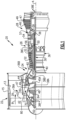
Figure 1 schematically illustrates agas turbine engine 20, Thegas turbine engine 20 is disclosed herein as a two-spool turbofan that generally incorporates afan section 22, acompressor section 24, a combustor section 26 and aturbine section 28, Thefan section 22 may include a single-stage fan 42 having a plurality offan blades 43. Thefan blades 43 may have a fixed stagger angle or may have a variable pitch to direct incoming airflow from an engine inlet. Thefan 42 drives air along a bypass flow path B in abypass duct 13 defined within ahousing 15 such as a fan case or nacelle, and also drives air along a core flow path C for compression and communication into the combustor section 26 then expansion through theturbine section 28. Asplitter 29 aft of thefan 42 divides the air between the bypass flow path B and the core flow path C. Thehousing 15 may surround thefan 42 to establish an outer diameter of thebypass duct 13. Thesplitter 29 may establish an inner diameter of thebypass duct 13. Although depicted as a two-spool turbofan gas turbine engine in the disclosed non-limiting embodiment, it should be understood that the concepts described herein are not limited to use with two-spool turbofans as the teachings may be applied to other types of turbine engines including three-spool architectures. Theengine 20 may incorporate a variable area nozzle for varying an exit area of the bypass flow path B and/or a thrust reverser for generating reverse thrust. - The
exemplary engine 20 generally includes alow speed spool 30 and ahigh speed spool 32 mounted for rotation about an engine central longitudinal axis A relative to an enginestatic structure 36 viaseveral bearing systems 38, It should be understood thatvarious bearing systems 38 at various locations may alternatively or additionally be provided, and the location ofbearing systems 38 may be varied as appropriate to the application. - The
low speed spool 30 generally includes aninner shaft 40 that interconnects, a first (or low)pressure compressor 44 and a first (or low) pressure turbine 46, Theinner shaft 40 is connected to thefan 42 through a speed change mechanism, which in the exemplarygas turbine engine 20 is illustrated as a gearedarchitecture 48 to drive thefan 42 at a lower speed than thelow speed spool 30. Theinner shaft 40 may interconnect thelow pressure compressor 44 and low pressure turbine 46 such that thelow pressure compressor 44 and low pressure turbine 46 are rotatable at a common speed and in a common direction. In other embodiments, the low pressure turbine 46 drives both thefan 42 andlow pressure compressor 44 through the gearedarchitecture 48 such that thefan 42 andlow pressure compressor 44 are rotatable at a common speed. Alternatively, thelow pressure compressor 44 includes aforward hub 45A and anaft hub 45B driven by theinner shaft 40. - Although this application discloses geared
architecture 48, its teaching may benefit direct drive engines having no geared architecture, Thehigh speed spool 32 includes anouter shaft 50 that interconnects a second (or high)pressure compressor 52 and a second (or high)pressure turbine 54, Acombustor 56 is arranged in theexemplary gas turbine 20 between thehigh pressure compressor 52 and thehigh pressure turbine 54, Amid-turbine frame 57 of the enginestatic structure 36 may be arranged generally between thehigh pressure turbine 54 and the low pressure turbine 46, Themid-turbine frame 57 furthersupports bearing systems 38 in theturbine section 28, In the illustrated example, themid-turbine frame 57 only includes abearing system 38 that supports thehigh spool 50 and themid-turbine frame 57 does not support thelow speed spool 30. Additionally, a pair of bearingsystems 38E are located adjacent a downstream end of thelow speed spool 30 adjacent an exhaust outlet of the gas turbine engine to support thelow speed spool 30. Furthermore, a bearingassembly 38C can be located radially inward from thecombustor 56 and supported by a diffuser case and be used in place of or in addition to thebearing system 38 associated with themid-turbine frame 57. Theinner shaft 40 and theouter shaft 50 are concentric and rotate via bearingsystems 38 about the engine central longitudinal axis A which is collinear with their longitudinal axes. - Airflow in the core flow path C is compressed by the
low pressure compressor 44 then thehigh pressure compressor 52, mixed and burned with fuel in thecombustor 56, then expanded through thehigh pressure turbine 54 and low pressure turbine 46, Themid-turbine frame 57 includesairfoils 59 which are in the core flow path C, Theturbines 46, 54 rotationally drive the respectivelow speed spool 30 andhigh speed spool 32 in response to the expansion, It will be appreciated that each of the positions of thefan section 22,compressor section 24, combustor section 26,turbine section 28, and fandrive gear system 48 may be varied, For example,gear system 48 may be located aft of the low pressure compressor, or aft of the combustor section 26 or even aft ofturbine section 28, andfan 42 may be positioned forward or aft of the location ofgear system 48. - The
low pressure compressor 44,high pressure compressor 52,high pressure turbine 54 and low pressure turbine 46 each include one or more stages having a row of rotatable airfoils. Each stage may include a row of vanes adjacent the rotatable airfoils. The rotatable airfoils are schematically indicated at 47, and the vanes are schematically indicated at 49. In one example, thelow pressure compressor 44 includes at least 4 stages and no more than 7 stages and in another example, thelow pressure compressor 44 includes at least 5 stages and no more than 7 stages. In both examples, thehigh pressure compressor 52 includes more stages than the low pressure compressor. - The
engine 20 may be a high-bypass geared aircraft engine. The bypass ratio can be greater than or equal to 10.0 and less than or equal to about 18.0, or more narrowly can be less than or equal to 16.0. The gearedarchitecture 48 may be an epicyclic gear train, such as a planetary gear system or a star gear system. The epicyclic gear train may include a sun gear, a ring gear, a plurality of intermediate gears meshing with the sun gear and ring gear, and a carrier that supports the intermediate gears. With the planetary gear system, the ring gear is fixed from rotation relative to the enginestatic structure 36 and the carrier rotates with thefan 42. With the star gear system, the carrier is fixed from rotation relative to the enginestatic structure 36 and the ring gear rotates with thefan 42. The sun gear may provide an input to the gear train. The ring gear (e.g., star gear system) or carrier (e.g., planetary gear system) may provide an output of the gear train to drive thefan 42. A gear reduction ratio may be greater than or equal to 2.3, or more narrowly greater than or equal to 3.0, and in some embodiments the gear reduction ratio is greater than or equal to 3.4, The gear reduction ratio may be less than or equal to 4.2, The fan diameter is significantly larger than that of thelow pressure compressor 44. The low pressure turbine 46 can have a pressure ratio that is greater than or equal to 8.0 and in some embodiments is greater than or equal to 10.0, The low pressure turbine pressure ratio can be less than or equal to 13.0, or more narrowly less than or equal to 12.0, Low pressure turbine 46 pressure ratio is pressure measured prior to an inlet of low pressure turbine 46 as related to the pressure at the outlet of the low pressure turbine 46 prior to an exhaust nozzle. It should be understood, however, that the above parameters are only exemplary of one embodiment of a geared architecture engine and that the present invention is applicable to other gas turbine engines including direct drive turbofans, All of these parameters are measured at the cruise condition described below. - A significant amount of thrust is provided by the bypass flow B due to the high bypass ratio, The
fan section 22 of theengine 20 is designed for a particular flight condition -- typically cruise at about 0.8 Mach and about 35,000 feet (10,668 meters), The flight condition of 0.8 Mach and 35,000 ft (10,668 meters), with the engine at its best fuel consumption - also known as "bucket cruise Thrust Specific Fuel Consumption ('TSFC')" - is the industry standard parameter of lbm of fuel being burned divided by lbf of thrust the engine produces at that minimum point, The engine parameters described above, and those in the next paragraph are measured at this condition unless otherwise specified. - "Fan pressure ratio" is the pressure ratio across the
fan blade 43 alone, without a Fan Exit Guide Vane ("FEGV") system, A distance is established in a radial direction between the inner and outer diameters of thebypass duct 13 at an axial position corresponding to a leading edge of thesplitter 29 relative to the engine central longitudinal axis A. The fan pressure ratio is a spanwise average of the pressure ratios measured across thefan blade 43 alone over radial positions corresponding to the distance. The fan pressure ratio can be less than or equal to 1.45, or more narrowly greater than or equal to 1.25, such as between 1.30 and 1.40, "Corrected fan tip speed" is the actual fan tip speed in ft/sec divided by an industry standard temperature correction of [(Tram °R) / (518.7 °R)]0.5 (where °R = 9/5 × K), The corrected fan tip speed can be less than or equal to 1150.0 ft / second (350.5 meters/second), and can be greater than or equal to 1000.0 ft / second (304.8 meters/second). - As shown in
Figure 1 , thelow speed spool 30 is supported by a number of bearingsystems 38. In particular, an axially forward end of thelow speed spool 30 adjacent the gearedarchitecture 48 is supported by a first low spool support bearing 38A and a second low spool support bearing 38B. Thefirst bearing 38A is located axially between thelow pressure compressor 44 and the gearedarchitecture 48. A location of attachment of thefirst bearing 38A with thelow speed spool 30 is located axially upstream of a location of attachment of thelow pressure compressor 44 to thelow speed spool 30 and the location of engagement of thefirst bearing 38A is axially downstream of the gearedarchitecture 48. Furthermore, a location of attachment of thesecond bearing 38B with thelow speed spool 30 is located axially downstream of the location of attachment of thelow pressure compressor 44 withlow speed spool 30 and axially upstream of thehigh pressure compressor 52 and thehigh speed spool 32. - In this disclosure, axial and radial directions are in relation to the engine axis A unless stated otherwise. Additionally, axially upstream and downstream directions are in relation to a direction of flow of air through the core flow path C unless stated otherwise.
- In the illustrated example, the first low spool support bearing 38A is supported by the engine
static structure 36 located axially forward of thelow pressure compressor 44. In the illustrated example, thefirst bearing 38A is supported by afront center body 36A of the enginestatic structure 36. An inner race of thefirst bearing 38A is configured to rotate with thelow speed spool 30 and an outer race of thefirst bearing 38A is fixed relative to thefront center body 36A. Thefront center body 36A provides structure support to a front of thegas turbine engine 20 forward of thelow pressure compressor 44. Thefront center body 36A can include structural vanes and/or struts 80 that pass through the core flow path C upstream of thelow pressure compressor 44. - In addition to supporting the
first bearing 38A, thefront center body 36A provides structural support for a pair of fanshaft support bearings 38F that support afan drive shaft 62. Thefan bearings 38F each include an inner race that is configured to rotate with thefan drive shaft 62 and an outer race fixed relative to thefront center body 36A of thestatic structure 36. Thefan drive shaft 62 is also in driving engagement with by an output of the gearedarchitecture 48. - As shown in
Figures 1-2 , the gearedarchitecture 48 provides an output through acarrier 64 that is configured to rotate with thefan drive shaft 62. Thecarrier 64 supports multiple planet gears 66 supported for rotation onbearings 72, such as journal bearings, relative to thecarrier 64. The planet gears 66 also surround a sun gear 68 that is in driving engagement with the low pressure turbine 46 through thelow speed spool 30. Aring gear 70 surrounds the planet gears 66 and is fixed from rotating relative to thefront center body 36A of the enginestatic structure 36. - The
second bearing 38B is supported by anintermediate case 36B of the enginestatic structure 36. The intermediate case is located axially aft of thelow pressure compressor 44 and axially forward of thehigh pressure compressor 52 and thehigh speed spool 32. An inner race of thesecond bearing 38B is configured to rotate with thelow speed spool 30 and an outer race of thesecond bearing 38B is fixed relative to theintermediate case 36B. - The
intermediate case 36B at least partially define a boundary of the core flow path C fluidly downstream of thelow pressure compressor 44 and upstream of thehigh pressure compressor 52. Theintermediate case 36B also includes at least onestructural support strut 82 radially spanning the core flow path C. Thestructure strut 80 can also be surrounded by an airfoil, such as an inlet guide vane, to turn air leaving thefan 42 and entering the core flow path C, A contour of the airfoil is determined based on a rotational direction of thefan 42 which determines a direction of movement of the air entering the core flow path C. - Although the different non-limiting examples are illustrated as having specific components, the examples of this disclosure are not limited to those particular combinations. It is possible to use some of the components or features from any of the non-limiting examples in combination with features or components from any of the other non-limiting examples.
- It should be understood that like reference numerals identify corresponding or similar elements throughout the several drawings. It should also be understood that although a particular component arrangement is disclosed and illustrated in these exemplary embodiments, other arrangements could also benefit from the teachings of this disclosure.
- The foregoing description shall be interpreted as illustrative and not in any limiting sense. A worker of ordinary skill in the art would understand that certain modifications could come within the scope of this disclosure. For these reasons, the following claim should be studied to determine the true scope and content of this disclosure.
Claims (15)
- A gas turbine engine (20) comprising:a fan section (22) including a fan (42) with fan blades (43), wherein said fan section (22) drives air along a bypass flow path (B) in a bypass duct (13);a gear reduction (48) in driving engagement with the fan (42), wherein the gear reduction (48) is a planetary gear system (48);a low spool (30) including a low pressure turbine (46) driving a low pressure compressor (44) and driving the gear reduction (48) to drive the fan (42) at a speed slower than the low pressure turbine (46);a high spool (32) including a high pressure turbine (54) driving a high pressure compressor (52);a first low spool support bearing (38A) located axially between the low pressure compressor (44) and the gear reduction (48); anda second low spool support bearing (38B) located axially between the low pressure compressor (44) and the high pressure compressor (52).
- The gas turbine engine (20) of claim 1, wherein the first low spool support bearing (38A) is supported by an engine static structure (36A) located axially forward of the low pressure compressor (44).
- The gas turbine engine (20) of claim 2, wherein the engine static structure (36A) located axially forward of the low pressure compressor (44) is a front center body (36A).
- The gas turbine engine (20) of claim 1, 2 or 3, wherein the second low spool support bearing (38B) is supported by an engine static structure (36B) located axially aft of the low pressure compressor (44).
- The gas turbine engine (20) of claim 4, wherein the engine static structure (36B) located axially aft of the low pressure compressor (44) is an intermediate case (36B), optionally wherein the intermediate case (36B) at least partially defines a portion of a core flow path (C) through the gas turbine engine (20) fluidly downstream of the low pressure compressor (44) and fluidly upstream of the high pressure compressor (52), optionally wherein the intermediate case (36B) includes at least one structural support strut (82) spanning the core flow path (C).
- The gas turbine engine (20) of any preceding claim, wherein an inner race of the first low spool support bearing (38A) is configured to rotate with the low spool (30), an outer race of the first low spool support bearing (38A) is fixed to a or the front center body (36A), an inner race of the second low spool support bearing (38B) is configured to rotate with the low spool (30), and an outer race of the second low spool support bearing (38B) is fixed to an or the intermediate case (36B).
- The gas turbine engine (20) of any preceding claim, including a mid-turbine frame (57) located axially between the high pressure turbine (54) and the low pressure turbine (46) and supporting an axially aft end of the high spool (32) and, optionally, including a pair of low spool support bearings (38E) located axially aft of the low pressure turbine (46), wherein the low spool (30) is unsupported by the mid-turbine frame (57).
- The gas turbine engine (20) of any preceding claim, wherein an or the aft end of the high spool (32) is supported by a bearing system (38C) engaging a diffuser case.
- The gas turbine engine (20) of any preceding claim, wherein the planetary gear system (48) includes a ring gear (70) fixed from rotating relative to the engine static structure (36) and a sun gear (68) in driving engagement with an input from the low spool (30).
- The gas turbine engine (20) of any preceding claim, wherein the fan section (22) includes a fan drive shaft (62) in driving engagement with the fan (42) and a pair of fan shaft support bearings (38F) supporting the fan drive shaft (62) relative to a or the front center body (36A), the gear reduction (48) includes a carrier (64) in driving engagement with the fan drive shaft (62).
- The gas turbine engine (20) of any preceding claim, wherein the low pressure compressor (44) includes at least 4 stages and no more than 7 stages and the high pressure compressor (52) includes more stages than the low pressure compressor (44), or wherein the low pressure compressor (44) includes at least 5 stages and no more than 7 stages and the high pressure compressor (52) includes more stages than the low pressure compressor (44).
- A method of supporting a low pressure compressor section, comprising:supporting a low pressure compressor (44) on a low spool (30) of a gas turbine engine (20) with a first low spool support bearing (38A) located axially forward of the low pressure compressor (44) and axially aft of a gear reduction (48), wherein the gear reduction (48) is in driving engagement with a fan section (22) and is a planetary gear system (48); andsupporting the low pressure compressor (44) with a second low spool support bearing (38B) located axially aft of the low pressure compressor (44).
- The method of claim 12, wherein the first low spool support bearing (38A) is supported by a front center body (36A) of an engine static structure (36) located axially forward of the low pressure compressor (44) and the second low spool support bearing (38B) is supported by an intermediate case (36B) of the engine static structure (36) located axially aft of the low pressure compressor (44).
- The method of claim 12 or 13, wherein the low pressure compressor (44) includes at least 4 stages and no more than 7 stages and a high pressure compressor (52) on a high spool (32) includes more stages than the low pressure compressor (44), or wherein the low pressure compressor (44) includes at least 5 stages and no more than 7 stages and a high pressure compressor (52) on a high spool (32) includes more stages than the low pressure compressor (44).
- The method of claim 12, 13 or 14, including supporting an aft end of a high spool (32) with support bearing supported by a mid-turbine frame (57) located axially between a high pressure turbine (54) and a low pressure turbine (46).
Applications Claiming Priority (1)
| Application Number | Priority Date | Filing Date | Title |
|---|---|---|---|
| US17/504,869 US20230121939A1 (en) | 2021-10-19 | 2021-10-19 | Straddle mounted low pressure compressor |
Publications (1)
| Publication Number | Publication Date |
|---|---|
| EP4170143A1 true EP4170143A1 (en) | 2023-04-26 |
Family
ID=84332300
Family Applications (1)
| Application Number | Title | Priority Date | Filing Date |
|---|---|---|---|
| EP22202508.2A Pending EP4170143A1 (en) | 2021-10-19 | 2022-10-19 | Straddle mounted low pressure compressor |
Country Status (2)
| Country | Link |
|---|---|
| US (1) | US20230121939A1 (en) |
| EP (1) | EP4170143A1 (en) |
Citations (5)
| Publication number | Priority date | Publication date | Assignee | Title |
|---|---|---|---|---|
| EP0203881A1 (en) * | 1985-05-29 | 1986-12-03 | United Technologies Corporation | Ducted prop engine |
| EP1918527A2 (en) * | 2006-10-31 | 2008-05-07 | General Electric Company | Gas turbine engine assembly and methods of assembling same |
| US20130192200A1 (en) * | 2012-01-31 | 2013-08-01 | United Technologies Corporation | Geared turbofan gas turbine engine architecture |
| US20140186158A1 (en) * | 2012-01-31 | 2014-07-03 | United Technologies Corporation | Gas turbine engine shaft bearing configuration |
| US20160084105A1 (en) * | 2014-09-24 | 2016-03-24 | United Technologies Corporation | Fan drive gear system |
Family Cites Families (9)
| Publication number | Priority date | Publication date | Assignee | Title |
|---|---|---|---|---|
| US3756672A (en) * | 1972-05-24 | 1973-09-04 | United Aircraft Corp | Shaft damping arrangement |
| US6230480B1 (en) * | 1998-08-31 | 2001-05-15 | Rollins, Iii William Scott | High power density combined cycle power plant |
| US8511605B2 (en) * | 2008-06-02 | 2013-08-20 | United Technologies Corporation | Gas turbine engine with low stage count low pressure turbine |
| US9938898B2 (en) * | 2011-07-29 | 2018-04-10 | United Technologies Corporation | Geared turbofan bearing arrangement |
| US9157325B2 (en) * | 2012-02-27 | 2015-10-13 | United Technologies Corporation | Buffer cooling system providing gas turbine engine architecture cooling |
| CA3013015C (en) * | 2012-06-15 | 2020-06-02 | United Technologies Corporation | High durability turbine exhaust case |
| US11339723B2 (en) * | 2012-10-01 | 2022-05-24 | Raytheon Technologies Corporation | Geared turbofan high gearbox power density |
| WO2014098962A1 (en) * | 2012-12-17 | 2014-06-26 | United Technologies Corporation | Two spool gas generator to create family of gas turbine engines |
| US20170051680A1 (en) * | 2015-08-18 | 2017-02-23 | General Electric Company | Airflow injection nozzle for a gas turbine engine |
-
2021
- 2021-10-19 US US17/504,869 patent/US20230121939A1/en active Pending
-
2022
- 2022-10-19 EP EP22202508.2A patent/EP4170143A1/en active Pending
Patent Citations (5)
| Publication number | Priority date | Publication date | Assignee | Title |
|---|---|---|---|---|
| EP0203881A1 (en) * | 1985-05-29 | 1986-12-03 | United Technologies Corporation | Ducted prop engine |
| EP1918527A2 (en) * | 2006-10-31 | 2008-05-07 | General Electric Company | Gas turbine engine assembly and methods of assembling same |
| US20130192200A1 (en) * | 2012-01-31 | 2013-08-01 | United Technologies Corporation | Geared turbofan gas turbine engine architecture |
| US20140186158A1 (en) * | 2012-01-31 | 2014-07-03 | United Technologies Corporation | Gas turbine engine shaft bearing configuration |
| US20160084105A1 (en) * | 2014-09-24 | 2016-03-24 | United Technologies Corporation | Fan drive gear system |
Also Published As
| Publication number | Publication date |
|---|---|
| US20230121939A1 (en) | 2023-04-20 |
Similar Documents
| Publication | Publication Date | Title |
|---|---|---|
| US11566586B2 (en) | Gas turbine engine shaft bearing configuration | |
| US10125694B2 (en) | Geared fan with inner counter rotating compressor | |
| US11927138B2 (en) | Fan drive gear system | |
| EP3101258B1 (en) | Geared architecture for a gas turbine engine and a corresponding method | |
| US20200386167A1 (en) | Geared turbofan with non-epicyclic gear reduction system | |
| US11162430B2 (en) | Geared gas turbine engine | |
| US20210010426A1 (en) | Gear reduction for lower thrust geared turbofan | |
| US20230122298A1 (en) | Fan drive gear system | |
| EP3825532A1 (en) | Geared architecture for gas turbine engine | |
| EP3825575A1 (en) | Geared architecture for gas turbine engine | |
| EP4170143A1 (en) | Straddle mounted low pressure compressor | |
| US20220154728A1 (en) | Repeating airfoil tip strong pressure profile | |
| EP3084142A1 (en) | Shortened support for compressor variable vane |
Legal Events
| Date | Code | Title | Description |
|---|---|---|---|
| PUAI | Public reference made under article 153(3) epc to a published international application that has entered the european phase |
Free format text: ORIGINAL CODE: 0009012 |
|
| STAA | Information on the status of an ep patent application or granted ep patent |
Free format text: STATUS: THE APPLICATION HAS BEEN PUBLISHED |
|
| AK | Designated contracting states |
Kind code of ref document: A1 Designated state(s): AL AT BE BG CH CY CZ DE DK EE ES FI FR GB GR HR HU IE IS IT LI LT LU LV MC ME MK MT NL NO PL PT RO RS SE SI SK SM TR |
|
| STAA | Information on the status of an ep patent application or granted ep patent |
Free format text: STATUS: REQUEST FOR EXAMINATION WAS MADE |
|
| RAP3 | Party data changed (applicant data changed or rights of an application transferred) |
Owner name: RTX CORPORATION |
|
| 17P | Request for examination filed |
Effective date: 20231026 |
|
| RBV | Designated contracting states (corrected) |
Designated state(s): AL AT BE BG CH CY CZ DE DK EE ES FI FR GB GR HR HU IE IS IT LI LT LU LV MC ME MK MT NL NO PL PT RO RS SE SI SK SM TR |