EP4169838A1 - Parachute riser cradle - Google Patents
Parachute riser cradle Download PDFInfo
- Publication number
- EP4169838A1 EP4169838A1 EP22203594.1A EP22203594A EP4169838A1 EP 4169838 A1 EP4169838 A1 EP 4169838A1 EP 22203594 A EP22203594 A EP 22203594A EP 4169838 A1 EP4169838 A1 EP 4169838A1
- Authority
- EP
- European Patent Office
- Prior art keywords
- riser
- parallel
- tandem
- coupled
- strap
- Prior art date
- Legal status (The legal status is an assumption and is not a legal conclusion. Google has not performed a legal analysis and makes no representation as to the accuracy of the status listed.)
- Granted
Links
Images




Classifications
-
- B—PERFORMING OPERATIONS; TRANSPORTING
- B64—AIRCRAFT; AVIATION; COSMONAUTICS
- B64D—EQUIPMENT FOR FITTING IN OR TO AIRCRAFT; FLIGHT SUITS; PARACHUTES; ARRANGEMENT OR MOUNTING OF POWER PLANTS OR PROPULSION TRANSMISSIONS IN AIRCRAFT
- B64D17/00—Parachutes
- B64D17/22—Load suspension
- B64D17/24—Rigging lines
-
- B—PERFORMING OPERATIONS; TRANSPORTING
- B64—AIRCRAFT; AVIATION; COSMONAUTICS
- B64D—EQUIPMENT FOR FITTING IN OR TO AIRCRAFT; FLIGHT SUITS; PARACHUTES; ARRANGEMENT OR MOUNTING OF POWER PLANTS OR PROPULSION TRANSMISSIONS IN AIRCRAFT
- B64D17/00—Parachutes
- B64D17/22—Load suspension
- B64D17/34—Load suspension adapted to control direction or rate of descent
-
- B—PERFORMING OPERATIONS; TRANSPORTING
- B64—AIRCRAFT; AVIATION; COSMONAUTICS
- B64D—EQUIPMENT FOR FITTING IN OR TO AIRCRAFT; FLIGHT SUITS; PARACHUTES; ARRANGEMENT OR MOUNTING OF POWER PLANTS OR PROPULSION TRANSMISSIONS IN AIRCRAFT
- B64D17/00—Parachutes
- B64D17/78—Parachutes in association with other load-retarding apparatus
-
- B—PERFORMING OPERATIONS; TRANSPORTING
- B64—AIRCRAFT; AVIATION; COSMONAUTICS
- B64D—EQUIPMENT FOR FITTING IN OR TO AIRCRAFT; FLIGHT SUITS; PARACHUTES; ARRANGEMENT OR MOUNTING OF POWER PLANTS OR PROPULSION TRANSMISSIONS IN AIRCRAFT
- B64D17/00—Parachutes
- B64D17/22—Load suspension
- B64D17/30—Harnesses
Definitions
- the present disclosure relates to parachutes, and more specifically, to parachutes and methods of making parachutes comprising a cradle to prevent injuries during deployment of the parachute.
- Parachutes may be used to slow and stabilize an object (e.g., an ejection seat or a person) supported by the parachute.
- Parachutes typically comprise a canopy to increase drag, and suspension lines coupled to the canopy.
- the suspension lines may be weaved or otherwise bound to one another to form risers configured to attach the object to the parachute and stabilize the object to reduce rotation while under canopy.
- a suspension line assembly for a parachute comprising a plurality of suspension lines bound together at a confluence, a first riser extending between the confluence and a first attachment location disposed on a first strap, a second riser extending between the confluence and a second attachment location disposed on a second strap, and a cradle disposed between the first riser and the second riser.
- a first parallel riser is coupled in parallel with the first riser
- a second parallel riser is coupled in parallel with the second riser
- a first tandem riser is coupled to the first parallel riser, and a second tandem riser is coupled to the second parallel riser.
- the cradle is coupled to the first tandem riser and the second tandem riser.
- a first set of horizontal straps is coupled to the first tandem riser and the first parallel riser, and a second set of horizontal straps is coupled to the second tandem riser and the second parallel riser.
- the first set of horizontal straps are between 0.5 inches to 8 inches (1.27 cm to 20.32 cm) apart from each other and the second set of horizontal straps are between 0.5 inches to 8 inches (1.27 cm to 20.32 cm) apart from each other.
- the first set of horizontal straps comprises a first navigational strap and the second set of horizontal straps comprises a second navigational strap, and the first navigational strap and the second navigational strap are configured to control steering of the parachute.
- the cradle comprises at least one of canvas, nylon, polyester, cotton, reinforcement fibers such as aramid and para-aramid fiber, and combinations of the same.
- a parachute assembly comprising a canopy and a suspension line assembly coupled to the canopy, the suspension line assembly comprising a plurality of suspension lines bound together at a confluence, a first riser coupled to the confluence, a first parallel riser coupled to the confluence in parallel with the first riser, a second riser coupled to the confluence, and a second parallel riser coupled to the confluence in parallel with the second riser.
- the suspension line assembly further comprises a first tandem riser coupled to the first parallel riser, and a second tandem riser coupled to the second parallel riser.
- the suspension line assembly further comprises a cradle coupled between the first tandem riser and the second tandem riser.
- the suspension line assembly further comprises a first set of horizontal straps coupled to the first tandem riser and the first parallel riser, and a second set of horizontal straps coupled to the second tandem riser and the second parallel riser.
- the first set of horizontal straps are between 0.5 inches to 8 inches (1.27 cm to 20.32 cm) apart from each other and the second set of horizontal straps are between 0.5 inches to 8 inches (1.27 cm to 20.32 cm) apart from each other.
- the first set of horizontal straps comprises a first navigational strap and the second set of horizontal straps comprises a second navigational strap.
- the first navigational strap and the second navigational strap are configured to control steering of the parachute assembly.
- the suspension line assembly is coupled to the canopy and a first attachment location disposed on a first strap.
- the cradle comprises at least one of canvas, nylon, polyester, cotton, reinforcement fibers such as aramid and para-aramid fiber, and combinations of the same.
- a method of making a parachute comprising forming a first riser by binding a first plurality of suspension lines together, forming a second riser by binding a second plurality of suspension lines together, forming a first confluence using the first plurality of suspension lines, forming a second confluence using the second plurality of suspension lines, coupling a first parallel riser in parallel with the first riser between the first confluence and a first attachment location, coupling a second parallel riser in parallel with the second riser between the second confluence and a second attachment location of the second riser, coupling a first tandem riser to the first parallel riser, and a second tandem riser to the second parallel riser, and coupling a cradle between the first tandem riser and the second tandem riser, wherein the first riser, the first parallel riser, the first tandem riser, the second riser, the second parallel riser, the second tandem riser and the cradle are compressed together when the parachute is in a stowed
- the method further comprises coupling a canopy to the first plurality of suspension lines and the second plurality of suspension lines.
- the method further comprises coupling a first set of horizontal straps between the first parallel riser and the first tandem riser, and coupling a second set of horizontal straps between the second parallel riser and the second tandem riser.
- any of the method or process descriptions may be executed in any order and are not necessarily limited to the order presented.
- any reference to singular includes plural embodiments, and any reference to more than one component or step may include a singular embodiment or step.
- any reference to tacked, attached, fixed, coupled, connected or the like may include permanent, removable, temporary, partial, full and/or any other possible attachment option.
- any reference to without contact (or similar phrases) may also include reduced contact or minimal contact.
- Surface shading lines may be used throughout the figures to denote different parts but not necessarily to denote the same or different materials.
- a parachute assembly including, in various embodiments, a suspension line assembly having risers and a cradle disposed between the risers.
- a parachute assembly When a parachute assembly is deployed there is a large amount of force put on the parachute assembly which is then transferred to the parachute operator.
- the cradle may be configured to dampen the forces applied to the parachute operator's neck and head during deployment of the parachute assembly.
- Parachute assembly 100 may comprise a canopy 102 and a suspension line assembly 104.
- Suspension line assembly 104 may comprise a first plurality of suspension lines 110, a first confluence 130 which splits into a first riser 120 and a first parallel riser 122, and a second plurality of suspension lines 115, a second confluence 132 which splits into a second riser 124 and a second parallel riser 126.
- suspension lines 110 and suspension lines 115 may be attached to canopy 102 at a first end 112 of suspension line assembly 104.
- first riser 120, the first parallel riser 122, the second riser 124, and the second parallel riser 126 may be configured to attach an object, such as an occupant harness 190, to parachute assembly 100.
- the occupant harness 190 comprises a first strap 140 and a second strap 142, with momentary reference to Figure 1 .
- first riser 120, and first parallel riser 122 may comprise a first attachment location 134.
- second riser 124, and second parallel riser 126 may comprise a second attachment location 138.
- First attachment location 134 and second attachment location 138 may be proximate a second end 136 of suspension line assembly 104.
- First attachment location 134 and second attachment location 138 may comprise any suitable attachment mechanism for securing an object to parachute assembly 100.
- first attachment location 134 and second attachment location 138 may comprise a loop created by each riser being bound to itself.
- attachment locations 134 and 138 may comprise a shackle.
- a cradle 150 is disposed between the first riser 120, and the second riser 124.
- a first tandem riser 202 may be coupled to the first parallel riser 122.
- the first tandem riser 202 may be coupled to the first parallel riser 122 by reinforced stitching, adhesives, or fabric bonding.
- a second tandem riser 204 may be coupled to the second parallel riser 126.
- the second tandem riser 204 may be coupled to the second parallel riser 126 by reinforced stitching, adhesives, or fabric bonding.
- the cradle 150 is disposed between the first riser 120 and the second riser 124. In various embodiments the cradle 150 is coupled to the first tandem riser 202 and the second tandem riser 204.
- the cradle 150 may comprise typical fabric materials like canvas, nylon, polyester, cotton, reinforcement fibers such as aramid and para-aramid fiber, and combinations of the same.
- the cradle 150 may be a rectangular shape such that it can wrap around a portion of the parachute operator. In various embodiments, the cradle 150 may be any suitable geometric shape.
- the cradle 150 may further be constructed with multiple panels, with or without gussets, to form a three-dimensional curve or other shape.
- the cradle 150 may be comprised of other suitable geometric shapes such as a square, a trapezoid or a circle.
- the cradle 150 may also be elastic and comprised of netting, webbing or the like.
- the cradle 150 may be attached to the first tandem riser 202 and the second tandem riser 204 such that there is space between the first parallel riser 122 and the first tandem riser 202, and there is space between the second parallel riser 126 and the second tandem riser 204.
- the space between the parallel risers and the tandem risers creates a window of visibility for the parachute operator which may be useful in an emergency situation.
- first riser 120, the first parallel riser 122, the second riser 124, and the second parallel riser 126 may be configured to attach an object, such as the occupant harness 190, to parachute assembly 100.
- the occupant harness may comprise a first strap 140 which attaches to the first attachment location 134.
- the occupant harness may comprise a second strap 142 which attaches to the second attachment location 138.
- first horizontal strap 208 coupled to the first parallel riser 122 and the first tandem riser 202.
- first set of horizontal straps comprised of more than one first horizontal strap 208.
- the first set of horizontal straps may also comprise a first navigational strap 210 coupled to the first parallel riser 122 and the first tandem riser 202.
- Navigational straps may be used by the parachute operator to steer the parachute assembly once it's in the deployed position 10.
- the second set of horizontal straps may also comprise a second navigational strap 216 coupled to the second parallel riser 126 and the second tandem riser 204.
- the first navigational strap 210 and the second navigational strap 216 are configured to control steering of the parachute assembly.
- the parachute operator may control the parachute assembly by placing a force on one or both of the first navigational strap 210 and the second navigational strap 212. Placing force on the navigational strap will create more drag in the canopy on the side the force is placed, which in allows the parachute operator to have navigational control of the parachute assembly.
- the horizontal straps also create a system that prevents the parachute operator from potentially getting an operator's head and/or neck stuck between a tandem riser and a parallel riser, which can cause injury.
- a suspension line assembly 300 comprises at least one first horizontal strap 208 coupled to the first parallel riser 122 and the first tandem riser 202.
- Each first horizontal strap 208 may be between 0.5 inches to 8 inches (1.27 cm to 20.32 cm) apart from each other, between 1 inch to 6 inches (2.54 cm to 15.24 cm) apart from each other, and between 2 inches to 4 inches (5.08 cm 10.16 cm) apart from each other.
- the first set of horizontal straps 212 may comprise four first horizontal straps 208.
- suspension line assembly 300 comprises at least one second horizontal strap 214 coupled to the second parallel riser 126 and the second tandem riser 204.
- Each second horizontal strap 214 may be between 0.5 inches to 8 inches (1.27 cm to 20.32 cm) apart from each other, between 1 inch to 6 inches (2.54 cm to 15.24 cm) apart from each other, and between 2 inches to 4 inches (5.08 cm 10.16 cm) apart from each other.
- the second set of horizontal straps 218 may comprise four second horizontal straps 214.
- Suspension line assembly 300 also comprises a cradle 150 which is coupled to the first tandem riser 202 and the second tandem riser 204.
- the suspension line assembly 300 may be disposed in a stowed position 400.
- the first riser 120, the first parallel riser 122, the first tandem riser 202, and the first set of horizontal straps 212 are compressed together via a non-permanent bonding means such as tacking.
- the second riser 124, the second parallel riser 126, the second tandem riser 204, and the second set of horizontal straps 218, are compressed together via a non-permanent bonding means such as tacking.
- the straps may be compressed together by other suitable non-permanent bonding means such that when the parachute assembly deploys then the straps may decompress and separate from each other such as in FIG. 3 .
- the cradle 150 is coupled to the first tandem riser 202 and the second tandem riser 204 by stitching, though coupling may also be achieved through use of adhesives, fabric bonding, rivets, other fasteners, and combinations of the same.
- the cradle 150 is compressed and its material is folded together in the stowed position 400.
- the cradle 150 material may be folded together in the manner of bellows to make the cradle 150 compact while in the stowed position 400.
- the cradle 150 may also be folded in the shape of a v while in the stowed position 400. Folding and compressing the cradle 150 while in the stowed position 400 allows for easier storage of the cradle 150 while the parachute is not deployed.
- Method 500 includes, forming the first riser 120 by binding the first plurality of suspension lines 110 together (step 510).
- Method 500 includes forming the second riser 124 by binding the second plurality of suspension lines 115 together (step 520).
- Method 500 includes forming the first confluence 130 using the first plurality of suspension lines 110 (step 530).
- Method 500 includes forming the second confluence 132 using the second plurality of suspension lines 115 (step 540).
- Method 500 includes coupling the first parallel riser 122 in parallel with the first riser 120 between the first confluence 130 and the first attachment location 134 (step 550).
- Method 500 includes coupling a second parallel riser 126 in parallel with the second riser 124 between the second confluence 132 and a second attachment location 138 (step 560).
- Method 500 includes coupling a first tandem riser 202 to the first parallel riser 122, and a second tandem riser 204 to the second parallel riser 126 (step 570).
- Method 500 includes coupling the cradle 150 between the first tandem riser 202 and the second tandem riser 204 (step 580).
- first riser 120, the first parallel riser 122, the first tandem riser 202, the second riser 124, the second parallel riser 126, the second tandem riser 204 and the cradle 150 are compressed together when the parachute is in the stowed position 400.
- first riser 120, the first parallel riser 122, the first tandem riser 202, the second riser 124, the second parallel riser 126, the second tandem riser 204 and the cradle 150 are decompressed in response to a deployed position 10 of the parachute assembly.
- method 500 may further comprise coupling the canopy 102 to the first plurality of suspension lines 110 and the second plurality of suspension lines 115. In various embodiments, method 500 may further comprise coupling the first plurality of horizontal straps 212 between the first parallel riser 122 and the first tandem riser 202 and coupling the second plurality of horizontal straps 218 between the second parallel riser 126 and the second tandem riser 204.
- references to "various embodiments”, “one embodiment”, “an embodiment”, “an example embodiment”, etc. indicate that the embodiment described may include a particular feature, structure, or characteristic, but every embodiment may not necessarily include the particular feature, structure, or characteristic. Moreover, such phrases are not necessarily referring to the same embodiment. Further, when a particular feature, structure, or characteristic is described in connection with an embodiment, it is submitted that it is within the knowledge of one skilled in the art to affect such feature, structure, or characteristic in connection with other embodiments whether or not explicitly described. After reading the description, it will be apparent to one skilled in the relevant art(s) how to implement the invention in alternative embodiments, within the scope of the claims.
Landscapes
- Engineering & Computer Science (AREA)
- Aviation & Aerospace Engineering (AREA)
- Toys (AREA)
Abstract
Description
- The present disclosure relates to parachutes, and more specifically, to parachutes and methods of making parachutes comprising a cradle to prevent injuries during deployment of the parachute.
- Parachutes may be used to slow and stabilize an object (e.g., an ejection seat or a person) supported by the parachute. Parachutes typically comprise a canopy to increase drag, and suspension lines coupled to the canopy. The suspension lines may be weaved or otherwise bound to one another to form risers configured to attach the object to the parachute and stabilize the object to reduce rotation while under canopy.
- A suspension line assembly for a parachute is disclosed, comprising a plurality of suspension lines bound together at a confluence, a first riser extending between the confluence and a first attachment location disposed on a first strap, a second riser extending between the confluence and a second attachment location disposed on a second strap, and a cradle disposed between the first riser and the second riser.
- In various embodiments, a first parallel riser is coupled in parallel with the first riser, and a second parallel riser is coupled in parallel with the second riser.
- In various embodiments, a first tandem riser is coupled to the first parallel riser, and a second tandem riser is coupled to the second parallel riser.
- In various embodiments, the cradle is coupled to the first tandem riser and the second tandem riser.
- In various embodiments, a first set of horizontal straps is coupled to the first tandem riser and the first parallel riser, and a second set of horizontal straps is coupled to the second tandem riser and the second parallel riser.
- In various embodiments, the first set of horizontal straps are between 0.5 inches to 8 inches (1.27 cm to 20.32 cm) apart from each other and the second set of horizontal straps are between 0.5 inches to 8 inches (1.27 cm to 20.32 cm) apart from each other.
- In various embodiments, the first set of horizontal straps comprises a first navigational strap and the second set of horizontal straps comprises a second navigational strap, and the first navigational strap and the second navigational strap are configured to control steering of the parachute.
- In various embodiments, wherein the cradle comprises at least one of canvas, nylon, polyester, cotton, reinforcement fibers such as aramid and para-aramid fiber, and combinations of the same.
- A parachute assembly is disclosed, comprising a canopy and a suspension line assembly coupled to the canopy, the suspension line assembly comprising a plurality of suspension lines bound together at a confluence, a first riser coupled to the confluence, a first parallel riser coupled to the confluence in parallel with the first riser, a second riser coupled to the confluence, and a second parallel riser coupled to the confluence in parallel with the second riser.
- In various embodiments, the suspension line assembly further comprises a first tandem riser coupled to the first parallel riser, and a second tandem riser coupled to the second parallel riser.
- In various embodiments, the suspension line assembly further comprises a cradle coupled between the first tandem riser and the second tandem riser.
- In various embodiments, the suspension line assembly further comprises a first set of horizontal straps coupled to the first tandem riser and the first parallel riser, and a second set of horizontal straps coupled to the second tandem riser and the second parallel riser.
- In various embodiments, the first set of horizontal straps are between 0.5 inches to 8 inches (1.27 cm to 20.32 cm) apart from each other and the second set of horizontal straps are between 0.5 inches to 8 inches (1.27 cm to 20.32 cm) apart from each other.
- In various embodiments, the first set of horizontal straps comprises a first navigational strap and the second set of horizontal straps comprises a second navigational strap.
- In various embodiments, the first navigational strap and the second navigational strap are configured to control steering of the parachute assembly.
- In various embodiments, the suspension line assembly is coupled to the canopy and a first attachment location disposed on a first strap.
- In various embodiments, the cradle comprises at least one of canvas, nylon, polyester, cotton, reinforcement fibers such as aramid and para-aramid fiber, and combinations of the same.
- A method of making a parachute is disclosed, comprising forming a first riser by binding a first plurality of suspension lines together, forming a second riser by binding a second plurality of suspension lines together, forming a first confluence using the first plurality of suspension lines, forming a second confluence using the second plurality of suspension lines, coupling a first parallel riser in parallel with the first riser between the first confluence and a first attachment location, coupling a second parallel riser in parallel with the second riser between the second confluence and a second attachment location of the second riser, coupling a first tandem riser to the first parallel riser, and a second tandem riser to the second parallel riser, and coupling a cradle between the first tandem riser and the second tandem riser, wherein the first riser, the first parallel riser, the first tandem riser, the second riser, the second parallel riser, the second tandem riser and the cradle are compressed together when the parachute is in a stowed position, and wherein the first riser, the first parallel riser, the first tandem riser, the second riser, the second parallel riser, the second tandem riser and the cradle are decompressed in response to a deployed position of the parachute.
- In various embodiments, the method further comprises coupling a canopy to the first plurality of suspension lines and the second plurality of suspension lines.
- In various embodiments, the method further comprises coupling a first set of horizontal straps between the first parallel riser and the first tandem riser, and coupling a second set of horizontal straps between the second parallel riser and the second tandem riser.
- The forgoing features and elements may be combined in various combinations without exclusivity, unless expressly indicated herein otherwise. These features and elements as well as the operation of the disclosed embodiments will become more apparent in light of the following description and accompanying drawings.
- The subject matter of the present disclosure is particularly pointed out and distinctly claimed in the concluding portion of the specification. A more complete understanding of the present disclosure, however, may best be obtained by referring to the detailed description and claims when considered in connection with the following illustrative figures. In the following figures, like reference numbers refer to similar elements and steps throughout the figures.
-
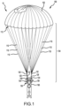
FIG. 1 illustrates a perspective view of a parachute assembly having risers in a deployed position, in accordance with various embodiments; -
FIG. 2 illustrates a perspective view of a suspension line assembly, in accordance with various embodiments; -
FIG. 3 illustrates a perspective view of the suspension line assembly, in accordance with various embodiments; -
FIG. 4a illustrates a perspective view of the suspension line assembly configured in a stowed position, in accordance with various embodiments; -
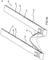
FIG. 4b illustrates a perspective view of the suspension line assembly configured in the stowed position, in accordance with various embodiments; -
FIG. 5 illustrates a method for making a parachute with various embodiments. - Elements and steps in the figures are illustrated for simplicity and clarity and have not necessarily been rendered according to any particular sequence. For example, steps that may be performed concurrently or in different order are illustrated in the figures to help to improve understanding of embodiments of the present disclosure.
- The detailed description of exemplary embodiments herein makes reference to the accompanying drawings, which show exemplary embodiments by way of illustration. While these exemplary embodiments are described in sufficient detail to enable those skilled in the art to practice the disclosures, it should be understood that other embodiments may be realized and that logical changes and adaptations in design and construction may be made in accordance with this disclosure and the teachings herein. Thus, the detailed description herein is presented for purposes of illustration only and not of limitation.
- The scope of the disclosure is defined by the appended claims and their legal equivalents rather than by merely the examples described. For example, the steps recited in any of the method or process descriptions may be executed in any order and are not necessarily limited to the order presented. Furthermore, any reference to singular includes plural embodiments, and any reference to more than one component or step may include a singular embodiment or step. Also, any reference to tacked, attached, fixed, coupled, connected or the like may include permanent, removable, temporary, partial, full and/or any other possible attachment option. Additionally, any reference to without contact (or similar phrases) may also include reduced contact or minimal contact. Surface shading lines may be used throughout the figures to denote different parts but not necessarily to denote the same or different materials.
- Disclosed herein is a parachute assembly including, in various embodiments, a suspension line assembly having risers and a cradle disposed between the risers. When a parachute assembly is deployed there is a large amount of force put on the parachute assembly which is then transferred to the parachute operator. The cradle may be configured to dampen the forces applied to the parachute operator's neck and head during deployment of the parachute assembly.
- With reference to
FIG. 1 , aparachute assembly 100 is illustrated in a deployedposition 10, in accordance with various embodiments.Parachute assembly 100 may comprise acanopy 102 and asuspension line assembly 104.Suspension line assembly 104 may comprise a first plurality ofsuspension lines 110, afirst confluence 130 which splits into afirst riser 120 and a firstparallel riser 122, and a second plurality ofsuspension lines 115, asecond confluence 132 which splits into asecond riser 124 and a secondparallel riser 126. In various embodiments,suspension lines 110 andsuspension lines 115 may be attached tocanopy 102 at afirst end 112 ofsuspension line assembly 104. - The
first riser 120, the firstparallel riser 122, thesecond riser 124, and the secondparallel riser 126 may be configured to attach an object, such as anoccupant harness 190, toparachute assembly 100. In various embodiments theoccupant harness 190 comprises afirst strap 140 and asecond strap 142, with momentary reference toFigure 1 . In various embodiments,first riser 120, and firstparallel riser 122, may comprise afirst attachment location 134. In various embodiments,second riser 124, and secondparallel riser 126, may comprise asecond attachment location 138.First attachment location 134 andsecond attachment location 138 may be proximate asecond end 136 ofsuspension line assembly 104.First attachment location 134 andsecond attachment location 138 may comprise any suitable attachment mechanism for securing an object to parachuteassembly 100. In various embodiments,first attachment location 134 andsecond attachment location 138 may comprise a loop created by each riser being bound to itself. In various embodiments,attachment locations cradle 150 is disposed between thefirst riser 120, and thesecond riser 124. - With additional reference to
FIG. 2 , afirst tandem riser 202 may be coupled to the firstparallel riser 122. In various embodiments, thefirst tandem riser 202 may be coupled to the firstparallel riser 122 by reinforced stitching, adhesives, or fabric bonding. In various embodiments, asecond tandem riser 204 may be coupled to the secondparallel riser 126. In various embodiments, thesecond tandem riser 204 may be coupled to the secondparallel riser 126 by reinforced stitching, adhesives, or fabric bonding. - In various embodiments the
cradle 150 is disposed between thefirst riser 120 and thesecond riser 124. In various embodiments thecradle 150 is coupled to thefirst tandem riser 202 and thesecond tandem riser 204. Thecradle 150 may comprise typical fabric materials like canvas, nylon, polyester, cotton, reinforcement fibers such as aramid and para-aramid fiber, and combinations of the same. Thecradle 150 may be a rectangular shape such that it can wrap around a portion of the parachute operator. In various embodiments, thecradle 150 may be any suitable geometric shape. Thecradle 150 may further be constructed with multiple panels, with or without gussets, to form a three-dimensional curve or other shape. Thecradle 150 may be comprised of other suitable geometric shapes such as a square, a trapezoid or a circle. Thecradle 150 may also be elastic and comprised of netting, webbing or the like. Thecradle 150 may be attached to thefirst tandem riser 202 and thesecond tandem riser 204 such that there is space between the firstparallel riser 122 and thefirst tandem riser 202, and there is space between the secondparallel riser 126 and thesecond tandem riser 204. The space between the parallel risers and the tandem risers creates a window of visibility for the parachute operator which may be useful in an emergency situation. - In various embodiments the
first riser 120, the firstparallel riser 122, thesecond riser 124, and the secondparallel riser 126 may be configured to attach an object, such as theoccupant harness 190, to parachuteassembly 100. The occupant harness may comprise afirst strap 140 which attaches to thefirst attachment location 134. In various embodiments the occupant harness may comprise asecond strap 142 which attaches to thesecond attachment location 138. - In various embodiments, there is at least one first
horizontal strap 208 coupled to the firstparallel riser 122 and thefirst tandem riser 202. In various embodiments, there may be a first set of horizontal straps comprised of more than one firsthorizontal strap 208. In various embodiments, the first set of horizontal straps may also comprise a firstnavigational strap 210 coupled to the firstparallel riser 122 and thefirst tandem riser 202. Navigational straps may be used by the parachute operator to steer the parachute assembly once it's in the deployedposition 10. In various embodiments there is at least one secondhorizontal strap 214 coupled to the secondparallel riser 126 and thesecond tandem riser 204. In various embodiments there may be a second set of horizontal straps comprised of more than one firsthorizontal strap 214. The second set of horizontal straps may also comprise a secondnavigational strap 216 coupled to the secondparallel riser 126 and thesecond tandem riser 204. - In various embodiments, the first
navigational strap 210 and the secondnavigational strap 216 are configured to control steering of the parachute assembly. In various embodiments, the parachute operator may control the parachute assembly by placing a force on one or both of the firstnavigational strap 210 and the secondnavigational strap 212. Placing force on the navigational strap will create more drag in the canopy on the side the force is placed, which in allows the parachute operator to have navigational control of the parachute assembly. The horizontal straps also create a system that prevents the parachute operator from potentially getting an operator's head and/or neck stuck between a tandem riser and a parallel riser, which can cause injury. - With combined reference to
FIGs. 1 ,2 , and3 , asuspension line assembly 300 comprises at least one firsthorizontal strap 208 coupled to the firstparallel riser 122 and thefirst tandem riser 202. In various embodiments there may be a first set ofhorizontal straps 212 comprised of more than one firsthorizontal strap 208 and at least one firstnavigational strap 210. Each firsthorizontal strap 208 may be between 0.5 inches to 8 inches (1.27 cm to 20.32 cm) apart from each other, between 1 inch to 6 inches (2.54 cm to 15.24 cm) apart from each other, and between 2 inches to 4 inches (5.08 cm 10.16 cm) apart from each other. In various embodiments, the first set ofhorizontal straps 212 may comprise four firsthorizontal straps 208. - In various embodiments,
suspension line assembly 300 comprises at least one secondhorizontal strap 214 coupled to the secondparallel riser 126 and thesecond tandem riser 204. In various embodiments, there may be a second set ofhorizontal straps 218 comprised of more than one secondhorizontal strap 214 and at least one secondnavigational strap 216. Each secondhorizontal strap 214 may be between 0.5 inches to 8 inches (1.27 cm to 20.32 cm) apart from each other, between 1 inch to 6 inches (2.54 cm to 15.24 cm) apart from each other, and between 2 inches to 4 inches (5.08 cm 10.16 cm) apart from each other. In various embodiments the second set ofhorizontal straps 218 may comprise four secondhorizontal straps 214.Suspension line assembly 300 also comprises acradle 150 which is coupled to thefirst tandem riser 202 and thesecond tandem riser 204. - With combined reference to
FIG. 3 ,FIG. 4a andFIG. 4b , thesuspension line assembly 300 may be disposed in a stowedposition 400. In the stowedposition 400 thefirst riser 120, the firstparallel riser 122, thefirst tandem riser 202, and the first set ofhorizontal straps 212, are compressed together via a non-permanent bonding means such as tacking. In the stowedposition 400 thesecond riser 124, the secondparallel riser 126, thesecond tandem riser 204, and the second set ofhorizontal straps 218, are compressed together via a non-permanent bonding means such as tacking. In various embodiments the straps may be compressed together by other suitable non-permanent bonding means such that when the parachute assembly deploys then the straps may decompress and separate from each other such as inFIG. 3 . - In various embodiments, the
cradle 150 is coupled to thefirst tandem riser 202 and thesecond tandem riser 204 by stitching, though coupling may also be achieved through use of adhesives, fabric bonding, rivets, other fasteners, and combinations of the same. In various embodiments, thecradle 150 is compressed and its material is folded together in the stowedposition 400. In various embodiments, thecradle 150 material may be folded together in the manner of bellows to make thecradle 150 compact while in the stowedposition 400. In various embodiments, thecradle 150 may also be folded in the shape of a v while in the stowedposition 400. Folding and compressing thecradle 150 while in the stowedposition 400 allows for easier storage of thecradle 150 while the parachute is not deployed. - With additional reference to
FIG. 1 ,FIG. 4a ,FIG 4b , andFIG. 5 , amethod 500 for forming theparachute assembly 100 is provided, in accordance with various embodiments.Method 500 includes, forming thefirst riser 120 by binding the first plurality ofsuspension lines 110 together (step 510).Method 500 includes forming thesecond riser 124 by binding the second plurality ofsuspension lines 115 together (step 520).Method 500 includes forming thefirst confluence 130 using the first plurality of suspension lines 110 (step 530).Method 500 includes forming thesecond confluence 132 using the second plurality of suspension lines 115 (step 540).Method 500 includes coupling the firstparallel riser 122 in parallel with thefirst riser 120 between thefirst confluence 130 and the first attachment location 134 (step 550).Method 500 includes coupling a secondparallel riser 126 in parallel with thesecond riser 124 between thesecond confluence 132 and a second attachment location 138 (step 560).Method 500 includes coupling afirst tandem riser 202 to the firstparallel riser 122, and asecond tandem riser 204 to the second parallel riser 126 (step 570).Method 500 includes coupling thecradle 150 between thefirst tandem riser 202 and the second tandem riser 204 (step 580). - In various embodiments, the
first riser 120, the firstparallel riser 122, thefirst tandem riser 202, thesecond riser 124, the secondparallel riser 126, thesecond tandem riser 204 and thecradle 150 are compressed together when the parachute is in the stowedposition 400. In various embodiments, thefirst riser 120, the firstparallel riser 122, thefirst tandem riser 202, thesecond riser 124, the secondparallel riser 126, thesecond tandem riser 204 and thecradle 150 are decompressed in response to a deployedposition 10 of the parachute assembly. - In various embodiments,
method 500 may further comprise coupling thecanopy 102 to the first plurality ofsuspension lines 110 and the second plurality of suspension lines 115. In various embodiments,method 500 may further comprise coupling the first plurality ofhorizontal straps 212 between the firstparallel riser 122 and thefirst tandem riser 202 and coupling the second plurality ofhorizontal straps 218 between the secondparallel riser 126 and thesecond tandem riser 204. - Benefits, other advantages, and solutions to problems have been described herein with regard to specific embodiments. Furthermore, the connecting lines shown in the various figures contained herein are intended to represent exemplary functional relationships and/or physical couplings between the various elements. It should be noted that many alternative or additional functional relationships or physical connections may be present in a practical system. However, the benefits, advantages, solutions to problems, and any elements that may cause any benefit, advantage, or solution to occur or become more pronounced are not to be construed as critical, required, or essential features or elements of the disclosures. The scope of the disclosures is accordingly to be limited by nothing other than the appended claims and their legal equivalents, in which reference to an element in the singular is not intended to mean "one and only one" unless explicitly so stated, but rather "one or more." Moreover, where a phrase similar to "at least one of A, B, or C" is used in the claims, it is intended that the phrase be interpreted to mean that A alone may be present in an embodiment, B alone may be present in an embodiment, C alone may be present in an embodiment, or that any combination of the elements A, B and C may be present in a single embodiment; for example, A and B, A and C, B and C, or A and B and C.
- Systems, methods, and apparatus are provided herein. In the detailed description herein, references to "various embodiments", "one embodiment", "an embodiment", "an example embodiment", etc., indicate that the embodiment described may include a particular feature, structure, or characteristic, but every embodiment may not necessarily include the particular feature, structure, or characteristic. Moreover, such phrases are not necessarily referring to the same embodiment. Further, when a particular feature, structure, or characteristic is described in connection with an embodiment, it is submitted that it is within the knowledge of one skilled in the art to affect such feature, structure, or characteristic in connection with other embodiments whether or not explicitly described. After reading the description, it will be apparent to one skilled in the relevant art(s) how to implement the invention in alternative embodiments, within the scope of the claims.
Claims (15)
- A suspension line assembly for a parachute assembly, comprising:a plurality of suspension lines (110) bound together at a confluence (130);a first riser (120) extending between the confluence and a first attachment location disposed on a first strap;a second riser (124) extending between the confluence and a second attachment location disposed on a second strap; anda cradle (150) disposed between the first riser and the second riser.
- The suspension line assembly of claim 1, further comprising:a first parallel riser (122) coupled in parallel with the first riser; anda second parallel riser (126) coupled in parallel with the second riser.
- The suspension line assembly of claim 2, further comprising:a first tandem riser (202) coupled to the first parallel riser; anda second tandem riser (204) coupled to the second parallel riser.
- The suspension line assembly of claim 3, wherein the cradle is coupled to the first tandem riser and the second tandem riser.
- The suspension line assembly of claim 4, further comprising:a first set of horizontal straps (208) coupled to the first tandem riser and the first parallel riser; anda second set of horizontal straps (214) coupled to the second tandem riser and the second parallel riser.
- The suspension line assembly of claim 5, wherein the first set of horizontal straps are between 0.5 inches to 8 inches (1.27 cm to 20.32 cm) apart from each other and the second set of horizontal straps are between 0.5 inches to 8 inches (1.27 cm to 20.32 cm) apart from each other.
- The suspension line assembly of claim 6, wherein the first set of horizontal straps comprises a first navigational strap (210) and the second set of horizontal straps comprises a second navigational strap (216).
- The suspension line assembly of claim 7, wherein the first navigational strap and the second navigational strap are configured to control steering of the parachute assembly.
- The suspension line assembly of any preceding claim, wherein the cradle comprises fabric.
- The suspension line assembly of claim 9, wherein the cradle comprises at least one of canvas, nylon, polyester, cotton, aramid fiber and para-aramid fiber.
- A parachute assembly, comprising:a canopy (102);a suspension line assembly (104) as claimed in claim 2 or any claim dependent thereon, coupled to the canopy.
- The parachute assembly of claim 11, wherein the suspension line assembly is coupled to the canopy and a first attachment location disposed on a first strap.
- A method of making a parachute assembly, comprising:forming a first riser (120) by binding a first plurality of suspension lines together;forming a second riser (124) by binding a second plurality of suspension lines together;forming a first confluence (130) using the first plurality of suspension lines;forming a second confluence (132) using the second plurality of suspension lines;coupling a first parallel riser (122) in parallel with the first riser between the first confluence and a first attachment location;coupling a second parallel riser (126) in parallel with the second riser between the second confluence and a second attachment location of the second riser;coupling a first tandem riser (202) to the first parallel riser, and a second tandem riser (204) to the second parallel riser;coupling a cradle (150) between the first tandem riser and the second tandem riser,wherein the first riser, the first parallel riser, the first tandem riser, the second riser, the second parallel riser, the second tandem riser and the cradle are compressed together when the parachute is in a stowed position, andwherein the first riser, the first parallel riser, the first tandem riser, the second riser, the second parallel riser, the second tandem riser and the cradle are decompressed in response to a deployed position of the parachute assembly.
- The method of claim 13, further comprising coupling a canopy (102) to the first plurality of suspension lines and the second plurality of suspension lines.
- The method of claim 14, further comprising coupling a first plurality of horizontal straps (208) between the first parallel riser and the first tandem riser, and
coupling a second plurality of horizontal straps (214) between the second parallel riser and the second tandem riser.
Applications Claiming Priority (1)
| Application Number | Priority Date | Filing Date | Title |
|---|---|---|---|
| US17/510,118 US11970274B2 (en) | 2021-10-25 | 2021-10-25 | Parachute riser cradle |
Publications (2)
| Publication Number | Publication Date |
|---|---|
| EP4169838A1 true EP4169838A1 (en) | 2023-04-26 |
| EP4169838B1 EP4169838B1 (en) | 2025-05-14 |
Family
ID=83996721
Family Applications (1)
| Application Number | Title | Priority Date | Filing Date |
|---|---|---|---|
| EP22203594.1A Active EP4169838B1 (en) | 2021-10-25 | 2022-10-25 | Parachute riser cradle |
Country Status (3)
| Country | Link |
|---|---|
| US (1) | US11970274B2 (en) |
| EP (1) | EP4169838B1 (en) |
| JP (1) | JP2023064065A (en) |
Citations (5)
| Publication number | Priority date | Publication date | Assignee | Title |
|---|---|---|---|---|
| FR2608392A1 (en) * | 1986-12-23 | 1988-06-24 | Millet Sacs | Backpack for paragliding (slope soaring) |
| DE4039516A1 (en) * | 1989-12-12 | 1991-06-20 | Bernhard Wenger | HARNESS FOR PARAGLIDER |
| US5904324A (en) * | 1995-03-24 | 1999-05-18 | Di Bella; Geoffrey | Non-motorized aircraft flight control system |
| FR2772717A1 (en) * | 1997-12-22 | 1999-06-25 | Tech Internationales De Mainte | Seat nacelle for paraglider pilot |
| US20150069186A1 (en) * | 2013-09-11 | 2015-03-12 | Uninsured United Parachute Technologies, LLC | Swooper Harness |
Family Cites Families (6)
| Publication number | Priority date | Publication date | Assignee | Title |
|---|---|---|---|---|
| US1857375A (en) * | 1930-06-14 | 1932-05-10 | Edward L Hoffman | Combination parachute harness |
| US3841590A (en) | 1971-07-22 | 1974-10-15 | Stanley Aviation Corp | Head restraint apparatus |
| GB2543351B (en) * | 2015-10-16 | 2021-10-27 | Martin Baker Aircraft Co Ltd | A parachute |
| US10946970B2 (en) * | 2018-09-21 | 2021-03-16 | Goodrich Corporation | Systems for removal of parachute assembly head restraints |
| US11027851B2 (en) * | 2018-09-21 | 2021-06-08 | Goodrich Corporation | Head restraint for parachute assemblies |
| US11021256B2 (en) * | 2018-09-21 | 2021-06-01 | Goodrich Corporation | Seat back head restrain for parachute assemblies |
-
2021
- 2021-10-25 US US17/510,118 patent/US11970274B2/en active Active
-
2022
- 2022-10-14 JP JP2022165123A patent/JP2023064065A/en active Pending
- 2022-10-25 EP EP22203594.1A patent/EP4169838B1/en active Active
Patent Citations (5)
| Publication number | Priority date | Publication date | Assignee | Title |
|---|---|---|---|---|
| FR2608392A1 (en) * | 1986-12-23 | 1988-06-24 | Millet Sacs | Backpack for paragliding (slope soaring) |
| DE4039516A1 (en) * | 1989-12-12 | 1991-06-20 | Bernhard Wenger | HARNESS FOR PARAGLIDER |
| US5904324A (en) * | 1995-03-24 | 1999-05-18 | Di Bella; Geoffrey | Non-motorized aircraft flight control system |
| FR2772717A1 (en) * | 1997-12-22 | 1999-06-25 | Tech Internationales De Mainte | Seat nacelle for paraglider pilot |
| US20150069186A1 (en) * | 2013-09-11 | 2015-03-12 | Uninsured United Parachute Technologies, LLC | Swooper Harness |
Also Published As
| Publication number | Publication date |
|---|---|
| JP2023064065A (en) | 2023-05-10 |
| EP4169838B1 (en) | 2025-05-14 |
| US20230126329A1 (en) | 2023-04-27 |
| US11970274B2 (en) | 2024-04-30 |
Similar Documents
| Publication | Publication Date | Title |
|---|---|---|
| US11027851B2 (en) | Head restraint for parachute assemblies | |
| US11046444B2 (en) | Inflatable head restraint for parachutes | |
| EP3403931B1 (en) | Off-wing slide raft | |
| US11242154B2 (en) | Yoke strap with shock absorber | |
| US20110174931A1 (en) | Airborne guidance unit for precision aerial delivery | |
| US10946970B2 (en) | Systems for removal of parachute assembly head restraints | |
| US11021256B2 (en) | Seat back head restrain for parachute assemblies | |
| JPH1191697A (en) | Expansible emergency slide assembly | |
| US10703495B2 (en) | Secondary release arrangement for evacuation slide systems | |
| US20220033095A1 (en) | Drogue parachute assemblies with elastomeric insert sleeves | |
| EP4169838B1 (en) | Parachute riser cradle | |
| US10625870B1 (en) | Secured lines for ballistic recovery system | |
| CA2422945C (en) | Flexible linkage system for environmentally sealed parachutes and other safety devices | |
| US12157576B2 (en) | Shock load attenuation | |
| EP3348485B1 (en) | Continuously restrained evacuation system | |
| US20210053661A1 (en) | Integrated lifeline and geometric restraint | |
| US12286233B2 (en) | Parachute assemblies with multi-stage reefing | |
| US12084189B2 (en) | Dual purpose life preserver and inflatable head restraint for parachute assemblies | |
| US11465761B2 (en) | Neck protection system for parachute assemblies | |
| US11130586B2 (en) | Lane dividing apparatus |
Legal Events
| Date | Code | Title | Description |
|---|---|---|---|
| PUAI | Public reference made under article 153(3) epc to a published international application that has entered the european phase |
Free format text: ORIGINAL CODE: 0009012 |
|
| STAA | Information on the status of an ep patent application or granted ep patent |
Free format text: STATUS: THE APPLICATION HAS BEEN PUBLISHED |
|
| AK | Designated contracting states |
Kind code of ref document: A1 Designated state(s): AL AT BE BG CH CY CZ DE DK EE ES FI FR GB GR HR HU IE IS IT LI LT LU LV MC ME MK MT NL NO PL PT RO RS SE SI SK SM TR |
|
| STAA | Information on the status of an ep patent application or granted ep patent |
Free format text: STATUS: REQUEST FOR EXAMINATION WAS MADE |
|
| P01 | Opt-out of the competence of the unified patent court (upc) registered |
Effective date: 20230922 |
|
| 17P | Request for examination filed |
Effective date: 20231026 |
|
| RBV | Designated contracting states (corrected) |
Designated state(s): AL AT BE BG CH CY CZ DE DK EE ES FI FR GB GR HR HU IE IS IT LI LT LU LV MC ME MK MT NL NO PL PT RO RS SE SI SK SM TR |
|
| GRAP | Despatch of communication of intention to grant a patent |
Free format text: ORIGINAL CODE: EPIDOSNIGR1 |
|
| STAA | Information on the status of an ep patent application or granted ep patent |
Free format text: STATUS: GRANT OF PATENT IS INTENDED |
|
| INTG | Intention to grant announced |
Effective date: 20241209 |
|
| GRAS | Grant fee paid |
Free format text: ORIGINAL CODE: EPIDOSNIGR3 |
|
| GRAA | (expected) grant |
Free format text: ORIGINAL CODE: 0009210 |
|
| STAA | Information on the status of an ep patent application or granted ep patent |
Free format text: STATUS: THE PATENT HAS BEEN GRANTED |
|
| AK | Designated contracting states |
Kind code of ref document: B1 Designated state(s): AL AT BE BG CH CY CZ DE DK EE ES FI FR GB GR HR HU IE IS IT LI LT LU LV MC ME MK MT NL NO PL PT RO RS SE SI SK SM TR |
|
| REG | Reference to a national code |
Ref country code: GB Ref legal event code: FG4D |
|
| REG | Reference to a national code |
Ref country code: CH Ref legal event code: EP |
|
| REG | Reference to a national code |
Ref country code: DE Ref legal event code: R096 Ref document number: 602022014592 Country of ref document: DE |
|
| REG | Reference to a national code |
Ref country code: IE Ref legal event code: FG4D |
|
| REG | Reference to a national code |
Ref country code: NL Ref legal event code: MP Effective date: 20250514 |
|
| PG25 | Lapsed in a contracting state [announced via postgrant information from national office to epo] |
Ref country code: ES Free format text: LAPSE BECAUSE OF FAILURE TO SUBMIT A TRANSLATION OF THE DESCRIPTION OR TO PAY THE FEE WITHIN THE PRESCRIBED TIME-LIMIT Effective date: 20250514 Ref country code: PT Free format text: LAPSE BECAUSE OF FAILURE TO SUBMIT A TRANSLATION OF THE DESCRIPTION OR TO PAY THE FEE WITHIN THE PRESCRIBED TIME-LIMIT Effective date: 20250915 Ref country code: FI Free format text: LAPSE BECAUSE OF FAILURE TO SUBMIT A TRANSLATION OF THE DESCRIPTION OR TO PAY THE FEE WITHIN THE PRESCRIBED TIME-LIMIT Effective date: 20250514 |
|
| REG | Reference to a national code |
Ref country code: LT Ref legal event code: MG9D |
|
| PG25 | Lapsed in a contracting state [announced via postgrant information from national office to epo] |
Ref country code: GR Free format text: LAPSE BECAUSE OF FAILURE TO SUBMIT A TRANSLATION OF THE DESCRIPTION OR TO PAY THE FEE WITHIN THE PRESCRIBED TIME-LIMIT Effective date: 20250815 Ref country code: NO Free format text: LAPSE BECAUSE OF FAILURE TO SUBMIT A TRANSLATION OF THE DESCRIPTION OR TO PAY THE FEE WITHIN THE PRESCRIBED TIME-LIMIT Effective date: 20250814 |
|
| PG25 | Lapsed in a contracting state [announced via postgrant information from national office to epo] |
Ref country code: NL Free format text: LAPSE BECAUSE OF FAILURE TO SUBMIT A TRANSLATION OF THE DESCRIPTION OR TO PAY THE FEE WITHIN THE PRESCRIBED TIME-LIMIT Effective date: 20250514 Ref country code: PL Free format text: LAPSE BECAUSE OF FAILURE TO SUBMIT A TRANSLATION OF THE DESCRIPTION OR TO PAY THE FEE WITHIN THE PRESCRIBED TIME-LIMIT Effective date: 20250514 |
|
| REG | Reference to a national code |
Ref country code: AT Ref legal event code: MK05 Ref document number: 1794614 Country of ref document: AT Kind code of ref document: T Effective date: 20250514 |
|
| PG25 | Lapsed in a contracting state [announced via postgrant information from national office to epo] |
Ref country code: BG Free format text: LAPSE BECAUSE OF FAILURE TO SUBMIT A TRANSLATION OF THE DESCRIPTION OR TO PAY THE FEE WITHIN THE PRESCRIBED TIME-LIMIT Effective date: 20250514 |
|
| PG25 | Lapsed in a contracting state [announced via postgrant information from national office to epo] |
Ref country code: HR Free format text: LAPSE BECAUSE OF FAILURE TO SUBMIT A TRANSLATION OF THE DESCRIPTION OR TO PAY THE FEE WITHIN THE PRESCRIBED TIME-LIMIT Effective date: 20250514 |
|
| PG25 | Lapsed in a contracting state [announced via postgrant information from national office to epo] |
Ref country code: AT Free format text: LAPSE BECAUSE OF FAILURE TO SUBMIT A TRANSLATION OF THE DESCRIPTION OR TO PAY THE FEE WITHIN THE PRESCRIBED TIME-LIMIT Effective date: 20250514 |
|
| PG25 | Lapsed in a contracting state [announced via postgrant information from national office to epo] |
Ref country code: RS Free format text: LAPSE BECAUSE OF FAILURE TO SUBMIT A TRANSLATION OF THE DESCRIPTION OR TO PAY THE FEE WITHIN THE PRESCRIBED TIME-LIMIT Effective date: 20250814 |
|
| PG25 | Lapsed in a contracting state [announced via postgrant information from national office to epo] |
Ref country code: IS Free format text: LAPSE BECAUSE OF FAILURE TO SUBMIT A TRANSLATION OF THE DESCRIPTION OR TO PAY THE FEE WITHIN THE PRESCRIBED TIME-LIMIT Effective date: 20250914 |
|
| PG25 | Lapsed in a contracting state [announced via postgrant information from national office to epo] |
Ref country code: LV Free format text: LAPSE BECAUSE OF FAILURE TO SUBMIT A TRANSLATION OF THE DESCRIPTION OR TO PAY THE FEE WITHIN THE PRESCRIBED TIME-LIMIT Effective date: 20250514 |
|
| PG25 | Lapsed in a contracting state [announced via postgrant information from national office to epo] |
Ref country code: SM Free format text: LAPSE BECAUSE OF FAILURE TO SUBMIT A TRANSLATION OF THE DESCRIPTION OR TO PAY THE FEE WITHIN THE PRESCRIBED TIME-LIMIT Effective date: 20250514 Ref country code: DK Free format text: LAPSE BECAUSE OF FAILURE TO SUBMIT A TRANSLATION OF THE DESCRIPTION OR TO PAY THE FEE WITHIN THE PRESCRIBED TIME-LIMIT Effective date: 20250514 |
|
| PG25 | Lapsed in a contracting state [announced via postgrant information from national office to epo] |
Ref country code: CZ Free format text: LAPSE BECAUSE OF FAILURE TO SUBMIT A TRANSLATION OF THE DESCRIPTION OR TO PAY THE FEE WITHIN THE PRESCRIBED TIME-LIMIT Effective date: 20250514 |
|
| PG25 | Lapsed in a contracting state [announced via postgrant information from national office to epo] |
Ref country code: EE Free format text: LAPSE BECAUSE OF FAILURE TO SUBMIT A TRANSLATION OF THE DESCRIPTION OR TO PAY THE FEE WITHIN THE PRESCRIBED TIME-LIMIT Effective date: 20250514 |
|
| PG25 | Lapsed in a contracting state [announced via postgrant information from national office to epo] |
Ref country code: SK Free format text: LAPSE BECAUSE OF FAILURE TO SUBMIT A TRANSLATION OF THE DESCRIPTION OR TO PAY THE FEE WITHIN THE PRESCRIBED TIME-LIMIT Effective date: 20250514 |
|
| PG25 | Lapsed in a contracting state [announced via postgrant information from national office to epo] |
Ref country code: IT Free format text: LAPSE BECAUSE OF FAILURE TO SUBMIT A TRANSLATION OF THE DESCRIPTION OR TO PAY THE FEE WITHIN THE PRESCRIBED TIME-LIMIT Effective date: 20250514 |
|
| PG25 | Lapsed in a contracting state [announced via postgrant information from national office to epo] |
Ref country code: RO Free format text: LAPSE BECAUSE OF FAILURE TO SUBMIT A TRANSLATION OF THE DESCRIPTION OR TO PAY THE FEE WITHIN THE PRESCRIBED TIME-LIMIT Effective date: 20250514 |
|
| REG | Reference to a national code |
Ref country code: DE Ref legal event code: R097 Ref document number: 602022014592 Country of ref document: DE |
|
| PLBE | No opposition filed within time limit |
Free format text: ORIGINAL CODE: 0009261 |
|
| STAA | Information on the status of an ep patent application or granted ep patent |
Free format text: STATUS: NO OPPOSITION FILED WITHIN TIME LIMIT |
|
| REG | Reference to a national code |
Ref country code: CH Ref legal event code: L10 Free format text: ST27 STATUS EVENT CODE: U-0-0-L10-L00 (AS PROVIDED BY THE NATIONAL OFFICE) Effective date: 20260325 |
|
| 26N | No opposition filed |
Effective date: 20260217 |