EP4169769A1 - Seat back energy absorber - Google Patents
Seat back energy absorber Download PDFInfo
- Publication number
- EP4169769A1 EP4169769A1 EP22198966.8A EP22198966A EP4169769A1 EP 4169769 A1 EP4169769 A1 EP 4169769A1 EP 22198966 A EP22198966 A EP 22198966A EP 4169769 A1 EP4169769 A1 EP 4169769A1
- Authority
- EP
- European Patent Office
- Prior art keywords
- support assembly
- seat
- dampening member
- die
- seat back
- Prior art date
- Legal status (The legal status is an assumption and is not a legal conclusion. Google has not performed a legal analysis and makes no representation as to the accuracy of the status listed.)
- Pending
Links
- 239000006096 absorbing agent Substances 0.000 title description 2
- 238000010521 absorption reaction Methods 0.000 claims abstract description 62
- 239000000463 material Substances 0.000 claims description 15
- 230000007423 decrease Effects 0.000 claims description 4
- 238000000034 method Methods 0.000 description 7
- 230000021715 photosynthesis, light harvesting Effects 0.000 description 5
- 230000007246 mechanism Effects 0.000 description 4
- 230000008859 change Effects 0.000 description 3
- 208000028373 Neck injury Diseases 0.000 description 2
- 238000005259 measurement Methods 0.000 description 2
- 238000012986 modification Methods 0.000 description 2
- 230000004048 modification Effects 0.000 description 2
- 230000008878 coupling Effects 0.000 description 1
- 238000010168 coupling process Methods 0.000 description 1
- 238000005859 coupling reaction Methods 0.000 description 1
- 238000006073 displacement reaction Methods 0.000 description 1
- 238000005516 engineering process Methods 0.000 description 1
- 238000002955 isolation Methods 0.000 description 1
- 230000009467 reduction Effects 0.000 description 1
Images


Classifications
-
- B—PERFORMING OPERATIONS; TRANSPORTING
- B60—VEHICLES IN GENERAL
- B60N—SEATS SPECIALLY ADAPTED FOR VEHICLES; VEHICLE PASSENGER ACCOMMODATION NOT OTHERWISE PROVIDED FOR
- B60N2/00—Seats specially adapted for vehicles; Arrangement or mounting of seats in vehicles
- B60N2/24—Seats specially adapted for vehicles; Arrangement or mounting of seats in vehicles for particular purposes or particular vehicles
- B60N2/42—Seats specially adapted for vehicles; Arrangement or mounting of seats in vehicles for particular purposes or particular vehicles the seat constructed to protect the occupant from the effect of abnormal g-forces, e.g. crash or safety seats
- B60N2/427—Seats or parts thereof displaced during a crash
- B60N2/42709—Seats or parts thereof displaced during a crash involving residual deformation or fracture of the structure
-
- B—PERFORMING OPERATIONS; TRANSPORTING
- B60—VEHICLES IN GENERAL
- B60N—SEATS SPECIALLY ADAPTED FOR VEHICLES; VEHICLE PASSENGER ACCOMMODATION NOT OTHERWISE PROVIDED FOR
- B60N2/00—Seats specially adapted for vehicles; Arrangement or mounting of seats in vehicles
- B60N2/24—Seats specially adapted for vehicles; Arrangement or mounting of seats in vehicles for particular purposes or particular vehicles
- B60N2/42—Seats specially adapted for vehicles; Arrangement or mounting of seats in vehicles for particular purposes or particular vehicles the seat constructed to protect the occupant from the effect of abnormal g-forces, e.g. crash or safety seats
- B60N2/4207—Seats specially adapted for vehicles; Arrangement or mounting of seats in vehicles for particular purposes or particular vehicles the seat constructed to protect the occupant from the effect of abnormal g-forces, e.g. crash or safety seats characterised by the direction of the g-forces
- B60N2/4214—Seats specially adapted for vehicles; Arrangement or mounting of seats in vehicles for particular purposes or particular vehicles the seat constructed to protect the occupant from the effect of abnormal g-forces, e.g. crash or safety seats characterised by the direction of the g-forces longitudinal
-
- B—PERFORMING OPERATIONS; TRANSPORTING
- B60—VEHICLES IN GENERAL
- B60N—SEATS SPECIALLY ADAPTED FOR VEHICLES; VEHICLE PASSENGER ACCOMMODATION NOT OTHERWISE PROVIDED FOR
- B60N2/00—Seats specially adapted for vehicles; Arrangement or mounting of seats in vehicles
- B60N2/64—Back-rests or cushions
- B60N2/66—Lumbar supports
-
- B—PERFORMING OPERATIONS; TRANSPORTING
- B60—VEHICLES IN GENERAL
- B60N—SEATS SPECIALLY ADAPTED FOR VEHICLES; VEHICLE PASSENGER ACCOMMODATION NOT OTHERWISE PROVIDED FOR
- B60N2/00—Seats specially adapted for vehicles; Arrangement or mounting of seats in vehicles
- B60N2/68—Seat frames
-
- B—PERFORMING OPERATIONS; TRANSPORTING
- B64—AIRCRAFT; AVIATION; COSMONAUTICS
- B64D—EQUIPMENT FOR FITTING IN OR TO AIRCRAFT; FLIGHT SUITS; PARACHUTES; ARRANGEMENT OR MOUNTING OF POWER PLANTS OR PROPULSION TRANSMISSIONS IN AIRCRAFT
- B64D11/00—Passenger or crew accommodation; Flight-deck installations not otherwise provided for
- B64D11/06—Arrangements of seats, or adaptations or details specially adapted for aircraft seats
- B64D11/0619—Arrangements of seats, or adaptations or details specially adapted for aircraft seats with energy absorbing means specially adapted for mitigating impact loads for passenger seats, e.g. at a crash
-
- B—PERFORMING OPERATIONS; TRANSPORTING
- B60—VEHICLES IN GENERAL
- B60N—SEATS SPECIALLY ADAPTED FOR VEHICLES; VEHICLE PASSENGER ACCOMMODATION NOT OTHERWISE PROVIDED FOR
- B60N2/00—Seats specially adapted for vehicles; Arrangement or mounting of seats in vehicles
- B60N2/02—Seats specially adapted for vehicles; Arrangement or mounting of seats in vehicles the seat or part thereof being movable, e.g. adjustable
- B60N2/22—Seats specially adapted for vehicles; Arrangement or mounting of seats in vehicles the seat or part thereof being movable, e.g. adjustable the back-rest being adjustable
-
- B—PERFORMING OPERATIONS; TRANSPORTING
- B60—VEHICLES IN GENERAL
- B60N—SEATS SPECIALLY ADAPTED FOR VEHICLES; VEHICLE PASSENGER ACCOMMODATION NOT OTHERWISE PROVIDED FOR
- B60N2205/00—General mechanical or structural details
- B60N2205/30—Seat or seat parts characterised by comprising plural parts or pieces
Definitions
- Passenger vehicles such as aircraft, buses, trains, ships, and automobiles, include passenger seats for passengers to sit in and utilize during travel.
- Some current seat-implemented solutions for improving passenger safety in the event of a crash have relied on a sufficiently strong seat structure, but such solutions are both heavy and costly to implement.
- Other current solutions for improving passenger safety do not allow for sufficient reduction in head velocities during a crash event and/or can result in high lumbar loads if the loads are not dissipated correctly.
- a passenger seat includes a seat base, a seat back pivotably connected to the seat base, and an energy absorption system spherically coupled to the seat base and spherically coupled to the seat back.
- the energy absorption system includes a dampening member and a support assembly, and the dampening member is movable relative to the support assembly such that engagement between the support assembly and the dampening member dampens a load on the seat back.
- the energy absorption system is configured to dampen the load and reduce a head impact criteria.
- the support assembly is on the dampening member such that the dampening member extends through the support assembly, and the dampening member is compressible as the dampening member moves through the support assembly.
- the support assembly is configured to decrease an outer diameter of the dampening member as the dampening member moves through the support assembly.
- the support assembly may include a material having a hardness is greater than a hardness of a material of the dampening member.
- the energy absorption system also includes a stop that provides a maximum movement limit for the dampening member.
- the support assembly is spherically coupled to the seat base and wherein the dampening member is spherically coupled to the seat back.
- the dampening member includes an elongated rod
- the support assembly includes a die comprising an inner wall defining a central aperture
- the elongated rod at least partially extends through the central aperture of the die such that the die is on the elongated rod.
- the elongated rod may be spherically coupled to the seat back and the die may be spherically coupled to the seat base.
- the elongated rod includes a first end and a second end opposite the first end, the first end is spherically coupled to the seat back, and the second end comprises a stop.
- the die may be on the elongated rod between the first end and the second end, and the die may engage the stop on the elongated rod at a maximum movement position of the elongated rod relative to the support assembly.
- at least a portion of the rod is hollow, and a wall thickness of the portion of the rod that is hollow is not constant.
- the rod may include an outer diameter, a first end, and a second end opposite from the first end, and the outer diameter is not constant between the first end and the second end. In some cases, the inner wall of the die is not constant.
- the support assembly includes a die spherically coupled to the seat base, and the dampening member includes an elongated rod and a crushable member.
- the elongated rod may extend at least partially through the die and be movable through the die.
- the elongated rod may include a first end spherically coupled to the seat back and a second end opposite from the first end.
- the crushable member may be on the elongated rod between the second end and the die, and the crushable member is deformed or crushed as the elongated rod moves through the die.
- the dampening member is pulled through the support assembly responsive to the load.
- a passenger seat includes a seat base having a forward end and an aft end, and a seat back pivotably connected to the seat base and having a top end and a bottom end.
- the passenger seat also includes an energy absorption system having a support assembly and a dampening member movable relative to and through the support assembly.
- the dampening member may be coupled to the seat back proximate to the bottom end of the seat back, and the support assembly may be coupled to the seat base proximate to the aft end of the seat base.
- the dampening member is movable relative to and through the support assembly responsive to a load on the seat back, and movement of the dampening member through the support assembly dampens the load.
- the support assembly is spherically coupled to the seat base and the dampening member is spherically coupled to the seat back.
- at least one of an outer diameter of the dampening member, a diameter of a central aperture of the support assembly, or a wall thickness of the dampening member is not constant.
- a method for dampening a load applied to a seat back of a passenger seat using an energy absorption system including at least one support assembly and at least one dampening member.
- the method includes receiving a load to a seat back, pivoting the seat back responsive to the applied load, and moving the at least one dampening member relative to the support assembly responsive to the load applied to the seat back to dampen the load and reduce a head impact criteria.
- a passenger seat includes a seat base, a pivotable seat back, and a seat belt coupled to an upper area of the pivotable seat back.
- the passenger seat also includes an energy absorption system spherically coupled to the seat base at a first attachment point and spherically coupled to the seat back at a second attachment point.
- the energy absorption system includes at least one support assembly and at least one dampening member movable relative to the support assembly responsive to a load applied to the pivotable seat back to dampen the load and reduce a head impact criteria
- the described embodiments of the invention provide energy absorption systems for passenger seats. While the energy absorption systems are discussed for use with aircraft seats, they are by no means so limited. Rather, embodiments of the energy absorption systems may be used in passenger seats or other seats of any type or otherwise as desired.
- the energy absorption systems described herein are provided on a seat back of a passenger seat and may allow for precise tuning and/or adjustment to provide a desired dampening or energy absorption during a dynamic event, including but not limited to a crash.
- the energy absorption systems described herein may reduce the loads imparted to the seat back during a dynamic event compared to traditional passenger seats.
- the energy absorption systems may also reduce head velocity or displacement during a dynamic event, which may provide lower Head Impact Criteria (HIC) measurements compared to traditional passenger seats.
- HIC Head Impact Criteria
- the energy absorption systems described herein may provide improved lumbar loads and/or neck injury criteria measurements during a dynamic event compared to traditional passenger seats.
- the energy absorption systems described herein may be used in conjunction with a safety belt such as a shoulder belt to further slow or reduce movement of the passenger during a dynamic event, and in some cases the energy absorption system may be optimized or adjusted for use with the safety belt. In some embodiments, the energy absorption systems may help dissipate energy over an extended period of time compared to traditional passenger seats.
- FIGS. 1-9 illustrate an example of a passenger seat 100 according to certain embodiments of the present invention.
- the passenger seat 100 includes a seat base 102 and a seat back 104 coupled to the seat base 102.
- the seat back 104 is pivotably coupled to the seat base 102 such that an angle or position of the seat back 104 can be adjusted as desired (e.g., between a taxiing, takeoff, and landing position and a reclined position).
- the seat base 102 generally includes a forward end 106 and an aft end 108
- the seat back 104 generally includes a top end 110 and a bottom end 112.
- the particular seat base 102 and seat back 104 illustrated should not be considered limiting, and in other embodiments the passenger seat 100 may include various other seat bases and/or seat backs as desired.
- the passenger seat 100 may include a safety belt 114 such as a shoulder strap or belt that a passenger may utilize while seated in the passenger seat 100.
- a safety belt 114 such as a shoulder strap or belt that a passenger may utilize while seated in the passenger seat 100.
- the particular safety belt 114 illustrated should not be considered limiting, and in other embodiments the safety belt 114 may be omitted.
- the passenger seat 100 includes at least one energy absorption system 116 for dampening loads during a dynamic event (discussed in greater detail below).
- the passenger seat 100 includes two energy absorption system 116, although any number could be used with the passenger seat 100 in other embodiments.
- an energy absorption system 116 may be coupled to both the seat base 102 and the seat back 104.
- the energy absorption system 116 may be coupled to the seat base 102 proximate to the aft end 108 and may be coupled to the seat back 104 proximate to the bottom end 112.
- the energy absorption system 116 may be spherically coupled to each of the seat base 102 and the seat back 104.
- the energy absorption system 116 spherically coupled to the seat base 102 and the seat back 104 may allow for an orientation of the energy absorption system 116 relative to the passenger seat 100 to change during a dynamic event while remaining coupled to the passenger seat 100.
- the energy absorption system 116 spherically coupled to the seat base 102 and the seat back 104 may optionally ensure that purely tensile loading is applied to the energy absorption system 116 during the dynamic event.
- Each energy absorption system 116 includes a support assembly 118 and a dampening member 120 that is movable relative to the support assembly 118.
- the dampening member 120 may include a stop 148 that engages the support assembly 118 at a maximum movement or stroke position of the dampening member 120 relative to the support assembly 118.
- the support assembly 118 may be spherically or otherwise coupled to the seat base 102 such that the support assembly 118 can rotate or otherwise change its orientation relative to the seat base 102.
- the dampening member 120 may be rotatably or otherwise coupled to the seat back 104 such that the dampening member 120 can rotate or otherwise change its orientation relative to the seat back 104.
- the support assembly 118 and the dampening member 120 may be constructed from various materials as desired, and in certain embodiments, the material of at least a portion of the support assembly 118 may optionally have a hardness that is greater than a hardness of the material of the dampening member 120.
- the support assembly 118 and/or dampening member 120 may be various devices or components as desired for dissipating energy during a dynamic event and dampening a load.
- the support assembly 118 includes a die 122 having a first end 124, a second end 126, and an inner wall 128 defining a central aperture 130 extending from the first end 124 to the second end 126.
- the central aperture 130 may have a shape such that the support assembly 118 can be at least partially positioned on the dampening member 120 and/or such that the dampening member 120 at least partially extends through the support assembly 118.
- Such characteristics may include, but are not limited to, a shape of the die 122, a shape of the central aperture 130, a material of the die 122, a length of the die 122, a transverse dimension (e.g., diameter) of the central aperture 130, combinations thereof, and/or other characteristics as desired.
- the central aperture 130 has a varying or nonconstant transverse dimension that progressively decreases from the first end 124 to the second end 126.
- the dampening member 120 is an elongated rod 132.
- the elongated rod 132 includes a first end 134, and second end 136, a connecting portion 138 for coupling the dampening member 120 to the seat back 104, and an engagement portion 140 for engaging the support assembly 118 and provide energy dissipation and load dampening during a dynamic event.
- the connecting portion 138 and the engagement portion 140 are separate components that are connected to each other using various techniques or mechanisms as desired; however, in other embodiments, the connecting portion 138 and engagement portion 140 may be monolithically or integrally formed as a single component.
- the connecting portion 138 and the engagement portion 140 are connected via threading forming a threaded engagement.
- the engagement portion 140 of the elongated rod 132 includes a wall 142.
- the wall 142 include a cavity 144 such that the engagement portion 140 is at least partially hollow, although in other embodiments it need not be hollow.
- one or more characteristics of the elongated rod 132 may be controlled as desired to provide a desired amount of energy dissipation and load dampening.
- Such characteristics may include, but are not limited to, a shape of the wall 142, a shape of the cavity 144, a material of the engagement portion 140 of the elongated rod 132, a length of the engagement portion 140 of the elongated rod 132, a transverse dimension (e.g., diameter) of the cavity 144, a thickness of the wall 142, combinations thereof, and/or other characteristics as desired.
- engagement portion 140 of the elongated rod 132 includes the wall 142 having a varying or nonconstant wall thickness, the wall 142 having an outer transverse dimension that is varying or nonconstant, and the cavity 144 having a varying shape.
- the die 122 When the energy absorption system 116 of FIGS. 1-9 is assembled, and as best illustrated in FIG. 8 , the die 122 is positioned on the elongated rod 132 between the first end 134 and the second end 136 of the elongated rod 132 and/or the elongated rod 132 extends at least partially through the central aperture 130 of the die 122.
- a load (represented by arrows 151) may be applied to the seat back 104.
- the energy absorption system 116 may accommodate increased loads on the seat bask 104 introduced by the safety belt 114.
- the loads applied to the seat back 104 during the dynamic event may cause the elongated rod 132 to be pulled through the die 122 (represented by arrows 146 in FIGS. 8 and 9 ).
- the elongated rod 132 moving through the die 122 engages the die 122 within the central aperture 130 (e.g., due to the varying transverse dimension of the central aperture 130 and/or the varying outer transverse dimension of the wall 142).
- Such engagement may cause the elongated rod 132 to compress and/or deform as the rod 132 is pulled through the die 122, thereby providing load dampening.
- the die 122 may reduce a diameter of the rod 132 as the rod 132 is pulled through the die.
- the stop 148 engages the support assembly 118, which may prevent further movement of the dampening member 120 through the support assembly 118.
- one or more characteristics of the support assembly 118 and/or the dampening member 120 may be controlled or adjusted as desired to provide a desired amount of energy dissipation and load dampening. Such characteristics may include, but are not limited to, materials, dimensions, inclusion or omission of features or components, combinations thereof, and/or other characteristics of the support assembly 118 and/or the dampening member 120 as desired.
- the one or more characteristics may be controlled to meet structural or passenger safety needs as desired.
- the one or more characteristics may optionally be controlled or adjusted as desired to improve HIC values, lumbar loads, neck injury criteria, seat structural loads, etc.
- the energy absorption system may be optimized for use with the safety belt 114, although it need not be in other embodiments.
- the one or more characteristics may be controlled to dissipate energy over an extended period of time,
- FIG. 10 illustrates another example of an energy absorption system 1016 according to various embodiments.
- the energy absorption system 1016 includes the die 122 as the support assembly 118 and includes an elongated rod 1032 and a crushable member 1052 as the dampening member 120.
- the elongated rod 1032 includes a first end 1054 and a second end 1056, and the elongated rod 1032 extends at least partially through the die 122.
- crushable member 1052 is supported on the elongated rod 1032 between the second end 1056 and the die 122.
- a passenger seat comprising: a seat base; a seat back pivotably connected to the seat base; and an energy absorption system spherically coupled to the seat base and spherically coupled to the seat back, the energy absorption system comprising a dampening member and a support assembly, wherein the dampening member is movable relative to the support assembly such that engagement between the support assembly and the dampening member dampens a load on the seat back.
- Illustration 2 The passenger seat of any preceding or subsequent illustrations or combination of illustrations, wherein the energy absorption system is configured to dampen the load and reduce a head impact criteria.
- Illustration 4 The passenger seat of any preceding or subsequent illustrations or combination of illustrations, wherein the support assembly is configured to decrease an outer diameter of the dampening member as the dampening member moves through the support assembly.
- Illustration 5 The passenger seat of any preceding or subsequent illustrations or combination of illustrations, wherein the support assembly comprises die, and wherein the die comprises a material having a hardness is greater than a hardness of a material of the dampening member.
- Illustration 7 The passenger seat of any preceding or subsequent illustrations or combination of illustrations, wherein the support assembly is spherically coupled to the seat base and wherein the dampening member is spherically coupled to the seat back.
- Illustration 8 The passenger seat of any preceding or subsequent illustrations or combination of illustrations, wherein the dampening member comprises an elongated rod, wherein the support assembly comprises a die comprising an inner wall defining a central aperture, and wherein the elongated rod at least partially extends through the central aperture of the die such that the die is on the elongated rod.
- Illustration 11 The passenger seat of any preceding or subsequent illustrations or combination of illustrations, wherein at least a portion of the rod is hollow, and wherein a wall thickness of the portion of the rod that is hollow is not constant.
- Illustration 12 The passenger seat of any preceding or subsequent illustrations or combination of illustrations, wherein the rod comprises an outer diameter, a first end, and a second end opposite from the first end, and wherein the outer diameter is not constant between the first end and the second end.
- Illustration 13 The passenger seat of any preceding or subsequent illustrations or combination of illustrations, wherein the inner wall of the die is not constant.
- Illustration 14 The passenger seat of any preceding or subsequent illustrations or combination of illustrations, wherein the support assembly comprises a die spherically coupled to the seat base, and wherein the dampening member comprises: an elongated rod extending at least partially through the die and movable through the die, the elongated rod comprising a first end spherically coupled to the seat back and a second end opposite from the first end; and a crushable member on the rod between the second end and the die, wherein the crushable member is deformed or crushed as the elongated rod moves through the die.
- the dampening member comprises: an elongated rod extending at least partially through the die and movable through the die, the elongated rod comprising a first end spherically coupled to the seat back and a second end opposite from the first end; and a crushable member on the rod between the second end and the die, wherein the crushable member is deformed or crushed as the elongated rod moves through the die.
- Illustration 15 The passenger seat of any preceding or subsequent illustrations or combination of illustrations, wherein the dampening member is pulled through the support assembly responsive to the load.
- a passenger seat comprising: a seat base; a seat back pivotably connected to the seat base; and an energy absorption system comprising a support assembly and a dampening member movable relative to the support assembly, wherein the support assembly is coupled to the seat base and the dampening member is coupled to the seat back, and wherein the dampening member is configured to selectively engage the support assembly responsive to a load on the seat back to dampen the load.
- Illustration 17 The passenger seat of any preceding or subsequent illustrations or combination of illustrations, wherein the support assembly is spherically coupled to the seat base and the dampening member is spherically coupled to the seat back.
- Illustration 18 The passenger seat of any preceding or subsequent illustrations or combination of illustrations, wherein the dampening member is movable through the support assembly responsive to the load, and wherein the dampening member is configured to selectively engage the support assembly such that the support assembly deforms, compresses, or frictionally engages the dampening member to dampen the load.
- Illustration 20 The passenger seat of any preceding or subsequent illustrations or combination of illustrations, wherein the support assembly is spherically coupled to the seat base and the dampening member is spherically coupled to the seat back, and wherein at least one of an outer diameter of the dampening member, a diameter of a central aperture of the support assembly, or a wall thickness of the dampening member is not constant.
- Illustrations 21 A method for dampening a load applied to a seat back of a passenger seat using an energy absorption system comprising at least one support assembly and at least one dampening member, the method comprising: receiving a load to a seat back; pivoting the seat back responsive to the applied load; moving the at least one dampening member relative to the support assembly responsive to the load applied to the seat back to dampen the load and reduce a head impact criteria.
- a passenger seat comprising: a seat base; a pivotable seat back; a seat belt coupled to an upper area of the pivotable seat back; an energy absorption system spherically coupled to the seat base at a first attachment point and spherically coupled to the seat back at a second attachment point, the energy absorption system comprising at least one support assembly and at least one dampening member movable relative to the support assembly responsive to a load applied to the pivotable seat back to dampen the load and reduce a head impact criteria.
Landscapes
- Engineering & Computer Science (AREA)
- Aviation & Aerospace Engineering (AREA)
- Transportation (AREA)
- Mechanical Engineering (AREA)
- Seats For Vehicles (AREA)
Abstract
Description
- The field of the invention relates to passenger seats, and, more particularly, to energy absorbers for passenger seats.
- Passenger vehicles, such as aircraft, buses, trains, ships, and automobiles, include passenger seats for passengers to sit in and utilize during travel. Some current seat-implemented solutions for improving passenger safety in the event of a crash have relied on a sufficiently strong seat structure, but such solutions are both heavy and costly to implement. Other current solutions for improving passenger safety do not allow for sufficient reduction in head velocities during a crash event and/or can result in high lumbar loads if the loads are not dissipated correctly.
- The terms "invention," "the invention," "this invention" and "the present invention" used in this patent are intended to refer broadly to all of the subject matter of this patent and the patent claims below. Statements containing these terms should be understood not to limit the subject matter described herein or to limit the meaning or scope of the patent claims below. Embodiments of the invention covered by this patent are defined by the claims below, not this summary. This summary is a high-level overview of various aspects of the invention and introduces some of the concepts that are further described in the Detailed Description section below. This summary is not intended to identify key or essential features of the claimed subject matter, nor is it intended to be used in isolation to determine the scope of the claimed subject matter. The subject matter should be understood by reference to appropriate portions of the entire specification of this patent, any or all drawings and each claim.
- According to certain embodiments of the present invention, a passenger seat includes a seat base, a seat back pivotably connected to the seat base, and an energy absorption system spherically coupled to the seat base and spherically coupled to the seat back. The energy absorption system includes a dampening member and a support assembly, and the dampening member is movable relative to the support assembly such that engagement between the support assembly and the dampening member dampens a load on the seat back.
- In some embodiments, the energy absorption system is configured to dampen the load and reduce a head impact criteria. In certain embodiments, the support assembly is on the dampening member such that the dampening member extends through the support assembly, and the dampening member is compressible as the dampening member moves through the support assembly. In various embodiments, the support assembly is configured to decrease an outer diameter of the dampening member as the dampening member moves through the support assembly.
- In certain aspects, at least a portion of the support assembly may include a material having a hardness is greater than a hardness of a material of the dampening member. In various embodiments, the energy absorption system also includes a stop that provides a maximum movement limit for the dampening member. In some embodiments, the support assembly is spherically coupled to the seat base and wherein the dampening member is spherically coupled to the seat back.
- In some examples, the dampening member includes an elongated rod, the support assembly includes a die comprising an inner wall defining a central aperture, and the elongated rod at least partially extends through the central aperture of the die such that the die is on the elongated rod. The elongated rod may be spherically coupled to the seat back and the die may be spherically coupled to the seat base. In certain embodiments, the elongated rod includes a first end and a second end opposite the first end, the first end is spherically coupled to the seat back, and the second end comprises a stop. The die may be on the elongated rod between the first end and the second end, and the die may engage the stop on the elongated rod at a maximum movement position of the elongated rod relative to the support assembly. In various embodiments, at least a portion of the rod is hollow, and a wall thickness of the portion of the rod that is hollow is not constant. According to various examples, the rod may include an outer diameter, a first end, and a second end opposite from the first end, and the outer diameter is not constant between the first end and the second end. In some cases, the inner wall of the die is not constant.
- In various embodiments, the support assembly includes a die spherically coupled to the seat base, and the dampening member includes an elongated rod and a crushable member. The elongated rod may extend at least partially through the die and be movable through the die. The elongated rod may include a first end spherically coupled to the seat back and a second end opposite from the first end. The crushable member may be on the elongated rod between the second end and the die, and the crushable member is deformed or crushed as the elongated rod moves through the die.
- In certain embodiments, the dampening member is pulled through the support assembly responsive to the load.
- According to certain embodiments of the present invention, a passenger seat includes a seat base, a seat back pivotably connected to the seat base, and an energy absorption system having a support assembly and a dampening member movable relative to the support assembly. The support assembly is coupled to the seat base and the dampening member is coupled to the seat back, and the dampening member is configured to selectively engage the support assembly responsive to a load on the seat back to dampen the load.
- In some embodiments, the support assembly is spherically coupled to the seat base and the dampening member is spherically coupled to the seat back. In various embodiments, the dampening member is movable through the support assembly responsive to the load, and the dampening member is configured to selectively engage the support assembly such that the support assembly deforms, compresses, or frictionally engages the dampening member to dampen the load.
- According to certain embodiments of the present invention, a passenger seat includes a seat base having a forward end and an aft end, and a seat back pivotably connected to the seat base and having a top end and a bottom end. The passenger seat also includes an energy absorption system having a support assembly and a dampening member movable relative to and through the support assembly. The dampening member may be coupled to the seat back proximate to the bottom end of the seat back, and the support assembly may be coupled to the seat base proximate to the aft end of the seat base. In certain embodiments, the dampening member is movable relative to and through the support assembly responsive to a load on the seat back, and movement of the dampening member through the support assembly dampens the load.
- In various embodiments, the support assembly is spherically coupled to the seat base and the dampening member is spherically coupled to the seat back. In some embodiments, at least one of an outer diameter of the dampening member, a diameter of a central aperture of the support assembly, or a wall thickness of the dampening member is not constant.
- According to certain embodiments of the present invention, a method is provided for dampening a load applied to a seat back of a passenger seat using an energy absorption system including at least one support assembly and at least one dampening member. The method includes receiving a load to a seat back, pivoting the seat back responsive to the applied load, and moving the at least one dampening member relative to the support assembly responsive to the load applied to the seat back to dampen the load and reduce a head impact criteria.
- According to certain embodiments of the present invention, a passenger seat includes a seat base, a pivotable seat back, and a seat belt coupled to an upper area of the pivotable seat back. The passenger seat also includes an energy absorption system spherically coupled to the seat base at a first attachment point and spherically coupled to the seat back at a second attachment point. The energy absorption system includes at least one support assembly and at least one dampening member movable relative to the support assembly responsive to a load applied to the pivotable seat back to dampen the load and reduce a head impact criteria
- Various implementations described in the present disclosure can include additional systems, methods, features, and advantages, which can not necessarily be expressly disclosed herein but will be apparent to one of ordinary skill in the art upon examination of the following detailed description and accompanying drawings. It is intended that all such systems, methods, features, and advantages be included within the present disclosure and protected by the accompanying claims.
-
-
FIG. 1 illustrates a passenger seat with an energy absorption system according to certain embodiments of the present invention. -
FIG. 2 illustrates the passenger seat ofFIG. 1 with a safety belt. -
FIG. 3 illustrates a portion of the passenger seat ofFIG. 1 . -
FIG. 4 illustrates another portion of the passenger seat ofFIG. 1 . -
FIG. 5 illustrates a support assembly and dampening member of the energy absorption system ofFIG. 1 . -
FIG. 6 illustrates a portion of the dampening member ofFIG. 5 . -
FIG. 7 illustrates the support assembly ofFIG. 5 -
FIG. 8 is a sectional view of the support assembly and dampening member ofFIG. 5 . -
FIG. 9 illustrates the passenger seat ofFIG. 1 being subjected to an impact load. -
FIG. 10 illustrates a portion of a passenger seat with an energy absorption system according to aspects of the present invention. -
FIG. 11 illustrates an energy absorption system according to aspects of the present invention. -
FIG. 12 is a sectional view of the energy absorption system ofFIG. 11 . - The subject matter of embodiments of the present invention is described here with specificity to meet statutory requirements, but this description is not necessarily intended to limit the scope of the claims. The claimed subject matter may be embodied in other ways, may include different elements or steps, and may be used in conjunction with other existing or future technologies. This description should not be interpreted as implying any particular order or arrangement among or between various steps or elements except when the order of individual steps or arrangement of elements is explicitly described.
- The described embodiments of the invention provide energy absorption systems for passenger seats. While the energy absorption systems are discussed for use with aircraft seats, they are by no means so limited. Rather, embodiments of the energy absorption systems may be used in passenger seats or other seats of any type or otherwise as desired.
- In certain embodiments, the energy absorption systems described herein are provided on a seat back of a passenger seat and may allow for precise tuning and/or adjustment to provide a desired dampening or energy absorption during a dynamic event, including but not limited to a crash. In various aspects, the energy absorption systems described herein may reduce the loads imparted to the seat back during a dynamic event compared to traditional passenger seats. The energy absorption systems may also reduce head velocity or displacement during a dynamic event, which may provide lower Head Impact Criteria (HIC) measurements compared to traditional passenger seats. In some embodiments, the energy absorption systems described herein may provide improved lumbar loads and/or neck injury criteria measurements during a dynamic event compared to traditional passenger seats. Optionally, the energy absorption systems described herein may be used in conjunction with a safety belt such as a shoulder belt to further slow or reduce movement of the passenger during a dynamic event, and in some cases the energy absorption system may be optimized or adjusted for use with the safety belt. In some embodiments, the energy absorption systems may help dissipate energy over an extended period of time compared to traditional passenger seats.
-
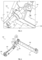
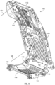
FIGS. 1-9 illustrate an example of apassenger seat 100 according to certain embodiments of the present invention. As best illustrated inFIG. 1 , thepassenger seat 100 includes aseat base 102 and a seat back 104 coupled to theseat base 102. In certain embodiments, the seat back 104 is pivotably coupled to theseat base 102 such that an angle or position of the seat back 104 can be adjusted as desired (e.g., between a taxiing, takeoff, and landing position and a reclined position). Theseat base 102 generally includes aforward end 106 and anaft end 108, and the seat back 104 generally includes atop end 110 and abottom end 112. Theparticular seat base 102 and seat back 104 illustrated should not be considered limiting, and in other embodiments thepassenger seat 100 may include various other seat bases and/or seat backs as desired. - Optionally, and as illustrated in
FIG. 2 , thepassenger seat 100 may include asafety belt 114 such as a shoulder strap or belt that a passenger may utilize while seated in thepassenger seat 100. Theparticular safety belt 114 illustrated should not be considered limiting, and in other embodiments thesafety belt 114 may be omitted. - In various embodiments, the
passenger seat 100 includes at least oneenergy absorption system 116 for dampening loads during a dynamic event (discussed in greater detail below). In the embodiment illustrated, thepassenger seat 100 includes twoenergy absorption system 116, although any number could be used with thepassenger seat 100 in other embodiments. As best illustrated inFIGS. 3 and 4 , anenergy absorption system 116 may be coupled to both theseat base 102 and the seat back 104. In certain embodiments, theenergy absorption system 116 may be coupled to theseat base 102 proximate to theaft end 108 and may be coupled to the seat back 104 proximate to thebottom end 112. In various embodiments, theenergy absorption system 116 may be spherically coupled to each of theseat base 102 and the seat back 104. Theenergy absorption system 116 spherically coupled to theseat base 102 and the seat back 104 may allow for an orientation of theenergy absorption system 116 relative to thepassenger seat 100 to change during a dynamic event while remaining coupled to thepassenger seat 100. In some embodiments, theenergy absorption system 116 spherically coupled to theseat base 102 and the seat back 104 may optionally ensure that purely tensile loading is applied to theenergy absorption system 116 during the dynamic event. - Each
energy absorption system 116 includes asupport assembly 118 and a dampeningmember 120 that is movable relative to thesupport assembly 118. Optionally, the dampeningmember 120 may include astop 148 that engages thesupport assembly 118 at a maximum movement or stroke position of the dampeningmember 120 relative to thesupport assembly 118. In certain embodiments, and as best illustrated inFIGS. 3 and 4 , thesupport assembly 118 may be spherically or otherwise coupled to theseat base 102 such that thesupport assembly 118 can rotate or otherwise change its orientation relative to theseat base 102. The dampeningmember 120 may be rotatably or otherwise coupled to the seat back 104 such that the dampeningmember 120 can rotate or otherwise change its orientation relative to the seat back 104. Thesupport assembly 118 and the dampeningmember 120 may be constructed from various materials as desired, and in certain embodiments, the material of at least a portion of thesupport assembly 118 may optionally have a hardness that is greater than a hardness of the material of the dampeningmember 120. - The
support assembly 118 and/or dampeningmember 120 may be various devices or components as desired for dissipating energy during a dynamic event and dampening a load. In the embodiment ofFIGS. 1-9 , and as best illustrated inFIGS. 7 and 8 , thesupport assembly 118 includes adie 122 having afirst end 124, asecond end 126, and aninner wall 128 defining acentral aperture 130 extending from thefirst end 124 to thesecond end 126. In certain embodiments, thecentral aperture 130 may have a shape such that thesupport assembly 118 can be at least partially positioned on the dampeningmember 120 and/or such that the dampeningmember 120 at least partially extends through thesupport assembly 118. In various embodiments, thedie 122 of thesupport assembly 118 is a material having a hardness that is greater than the hardness of the material of the dampeningmember 120. The particular shape and/or features of the die 122 illustrated should not be considered limiting, and in other embodiments thesupport assembly 118 need not include adie 122, and other suitable devices or components for engaging the dampeningmember 120 may be used as desired. In certain aspects, one or more characteristics of thedie 122 may be controlled as desired to provide a desired amount of energy dissipation and load dampening. Such characteristics may include, but are not limited to, a shape of thedie 122, a shape of thecentral aperture 130, a material of thedie 122, a length of thedie 122, a transverse dimension (e.g., diameter) of thecentral aperture 130, combinations thereof, and/or other characteristics as desired. As best illustrated inFIG. 8 and as discussed in detail below, in the embodiment illustrated, thecentral aperture 130 has a varying or nonconstant transverse dimension that progressively decreases from thefirst end 124 to thesecond end 126. - In the embodiment of
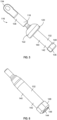
FIGS. 1-9 , and as best illustrated inFIGS. 5, 6 , and8 , the dampeningmember 120 is anelongated rod 132. Theelongated rod 132 includes afirst end 134, andsecond end 136, a connectingportion 138 for coupling the dampeningmember 120 to the seat back 104, and anengagement portion 140 for engaging thesupport assembly 118 and provide energy dissipation and load dampening during a dynamic event. In the embodiment illustrated, the connectingportion 138 and theengagement portion 140 are separate components that are connected to each other using various techniques or mechanisms as desired; however, in other embodiments, the connectingportion 138 andengagement portion 140 may be monolithically or integrally formed as a single component. In the embodiment illustrated, the connectingportion 138 and theengagement portion 140 are connected via threading forming a threaded engagement. - The
engagement portion 140 of theelongated rod 132 includes awall 142. Optionally, thewall 142 include acavity 144 such that theengagement portion 140 is at least partially hollow, although in other embodiments it need not be hollow. Similar to thedie 122, one or more characteristics of theelongated rod 132 may be controlled as desired to provide a desired amount of energy dissipation and load dampening. Such characteristics may include, but are not limited to, a shape of thewall 142, a shape of thecavity 144, a material of theengagement portion 140 of theelongated rod 132, a length of theengagement portion 140 of theelongated rod 132, a transverse dimension (e.g., diameter) of thecavity 144, a thickness of thewall 142, combinations thereof, and/or other characteristics as desired. As best illustrated inFIG. 8 and as discussed in detail below, in the embodiment illustrated,engagement portion 140 of theelongated rod 132 includes thewall 142 having a varying or nonconstant wall thickness, thewall 142 having an outer transverse dimension that is varying or nonconstant, and thecavity 144 having a varying shape. - When the
energy absorption system 116 ofFIGS. 1-9 is assembled, and as best illustrated inFIG. 8 , thedie 122 is positioned on theelongated rod 132 between thefirst end 134 and thesecond end 136 of theelongated rod 132 and/or theelongated rod 132 extends at least partially through thecentral aperture 130 of thedie 122. - Referring to
FIG. 9 , during a dynamic event, a load (represented by arrows 151) may be applied to the seat back 104. In cases including thesafety belt 114, theenergy absorption system 116 may accommodate increased loads on the seat bask 104 introduced by thesafety belt 114. - The loads applied to the seat back 104 during the dynamic event may cause the
elongated rod 132 to be pulled through the die 122 (represented byarrows 146 inFIGS. 8 and9 ). In the embodiment ofFIGS. 1-9 , theelongated rod 132 moving through thedie 122 engages thedie 122 within the central aperture 130 (e.g., due to the varying transverse dimension of thecentral aperture 130 and/or the varying outer transverse dimension of the wall 142). Such engagement may cause theelongated rod 132 to compress and/or deform as therod 132 is pulled through thedie 122, thereby providing load dampening. In some cases, thedie 122 may reduce a diameter of therod 132 as therod 132 is pulled through the die. At a maximum movement or stroke position, thestop 148 engages thesupport assembly 118, which may prevent further movement of the dampeningmember 120 through thesupport assembly 118. - As mentioned, one or more characteristics of the
support assembly 118 and/or the dampeningmember 120 may be controlled or adjusted as desired to provide a desired amount of energy dissipation and load dampening. Such characteristics may include, but are not limited to, materials, dimensions, inclusion or omission of features or components, combinations thereof, and/or other characteristics of thesupport assembly 118 and/or the dampeningmember 120 as desired. In certain embodiments, the one or more characteristics may be controlled to meet structural or passenger safety needs as desired. In some cases, the one or more characteristics may optionally be controlled or adjusted as desired to improve HIC values, lumbar loads, neck injury criteria, seat structural loads, etc. Optionally, the energy absorption system may be optimized for use with thesafety belt 114, although it need not be in other embodiments. In certain embodiments, the one or more characteristics may be controlled to dissipate energy over an extended period of time, -
FIG. 10 illustrates another example of anenergy absorption system 1016 according to various embodiments. Compared to theenergy absorption system 116, theenergy absorption system 1016 includes the die 122 as thesupport assembly 118 and includes anelongated rod 1032 and acrushable member 1052 as the dampeningmember 120. Theelongated rod 1032 includes afirst end 1054 and asecond end 1056, and theelongated rod 1032 extends at least partially through thedie 122. In this embodiment, and as illustrated inFIG. 10 ,crushable member 1052 is supported on theelongated rod 1032 between thesecond end 1056 and thedie 122. Responsive to a load from a dynamic event, therod 1032 may be pulled through thedie 122, and such movement deforms and/or crushes thecrushable member 1052 to provide the load dampening. In this embodiment, thecrushable member 1052 may be various materials that can be at least selectively crushed and/or deformed to provide energy absorption. -
FIGS. 11 and 12 illustrate another example of anenergy absorption system 1116. Compared to theenergy absorption system 116, theenergy absorption system 1116 includes the die 122 as thesupport assembly 118 and an elongated rod 1132 and afriction mechanism 1150 as the dampeningmember 120. Compared to theelongated rod 132, the elongated rod 1132 is a monolithic or integrally formed component. Thefriction mechanism 1150 may include afirst component 1158 and asecond component 1160 that selectively, frictionally engage each other responsive to a dynamic event to provide load dampening. Optionally, thefirst component 1158 may at least partially receive thesecond component 1160 responsive to the dynamic event and to frictionally engage thesecond component 1160. In certain aspects, at least one characteristic of thefirst component 1158 and/or thesecond component 1160 may be controlled as desired to provide a desired amount of energy dissipation. Various other types of friction mechanisms may be used in other embodiments as desired, and as mentioned, other devices or components may be used as thesupport assembly 118 and/or the dampeningmember 120 as desired. - A collection of exemplary embodiments are provided below, including at least some explicitly enumerated as "Illustrations" providing additional description of a variety of example embodiments in accordance with the concepts described herein. These illustrations are not meant to be mutually exclusive, exhaustive, or restrictive; and the disclosure not limited to these example illustrations but rather encompasses all possible modifications and variations within the scope of the issued claims and their equivalents.
- Illustration 1. A passenger seat comprising: a seat base; a seat back pivotably connected to the seat base; and an energy absorption system spherically coupled to the seat base and spherically coupled to the seat back, the energy absorption system comprising a dampening member and a support assembly, wherein the dampening member is movable relative to the support assembly such that engagement between the support assembly and the dampening member dampens a load on the seat back.
- Illustration 2. The passenger seat of any preceding or subsequent illustrations or combination of illustrations, wherein the energy absorption system is configured to dampen the load and reduce a head impact criteria.
- Illustration 3. The passenger seat of any preceding or subsequent illustrations or combination of illustrations, wherein the support assembly is on the dampening member such that the dampening member extends through the support assembly, and wherein the dampening member is compressible as the dampening member moves through the support assembly.
- Illustration 4. The passenger seat of any preceding or subsequent illustrations or combination of illustrations, wherein the support assembly is configured to decrease an outer diameter of the dampening member as the dampening member moves through the support assembly.
- Illustration 5. The passenger seat of any preceding or subsequent illustrations or combination of illustrations, wherein the support assembly comprises die, and wherein the die comprises a material having a hardness is greater than a hardness of a material of the dampening member.
- Illustration 6. The passenger seat of any preceding or subsequent illustrations or combination of illustrations, wherein the energy absorption system further comprises a stop that provides a maximum movement limit for the dampening member.
- Illustration 7. The passenger seat of any preceding or subsequent illustrations or combination of illustrations, wherein the support assembly is spherically coupled to the seat base and wherein the dampening member is spherically coupled to the seat back.
- Illustration 8. The passenger seat of any preceding or subsequent illustrations or combination of illustrations, wherein the dampening member comprises an elongated rod, wherein the support assembly comprises a die comprising an inner wall defining a central aperture, and wherein the elongated rod at least partially extends through the central aperture of the die such that the die is on the elongated rod.
- Illustration 9. The passenger seat of any preceding or subsequent illustrations or combination of illustrations, wherein the elongated rod is spherically coupled to the seat back and wherein the die is spherically coupled to the seat base.
- Illustration 10. The passenger seat of any preceding or subsequent illustrations or combination of illustrations, wherein the elongated rod comprises a first end and a second end opposite the first end, wherein the first end is spherically coupled to the seat back, wherein the second end comprises a stop, wherein the die is on the elongated rod between the first end and the second end, and wherein the die is configured to engage the stop on the elongated rod at a maximum movement position of the elongated rod relative to the support assembly.
- Illustration 11. The passenger seat of any preceding or subsequent illustrations or combination of illustrations, wherein at least a portion of the rod is hollow, and wherein a wall thickness of the portion of the rod that is hollow is not constant.
- Illustration 12. The passenger seat of any preceding or subsequent illustrations or combination of illustrations, wherein the rod comprises an outer diameter, a first end, and a second end opposite from the first end, and wherein the outer diameter is not constant between the first end and the second end.
- Illustration 13. The passenger seat of any preceding or subsequent illustrations or combination of illustrations, wherein the inner wall of the die is not constant.
- Illustration 14. The passenger seat of any preceding or subsequent illustrations or combination of illustrations, wherein the support assembly comprises a die spherically coupled to the seat base, and wherein the dampening member comprises: an elongated rod extending at least partially through the die and movable through the die, the elongated rod comprising a first end spherically coupled to the seat back and a second end opposite from the first end; and a crushable member on the rod between the second end and the die, wherein the crushable member is deformed or crushed as the elongated rod moves through the die.
- Illustration 15. The passenger seat of any preceding or subsequent illustrations or combination of illustrations, wherein the dampening member is pulled through the support assembly responsive to the load.
- Illustration 16. A passenger seat comprising: a seat base; a seat back pivotably connected to the seat base; and an energy absorption system comprising a support assembly and a dampening member movable relative to the support assembly, wherein the support assembly is coupled to the seat base and the dampening member is coupled to the seat back, and wherein the dampening member is configured to selectively engage the support assembly responsive to a load on the seat back to dampen the load.
- Illustration 17. The passenger seat of any preceding or subsequent illustrations or combination of illustrations, wherein the support assembly is spherically coupled to the seat base and the dampening member is spherically coupled to the seat back.
- Illustration 18. The passenger seat of any preceding or subsequent illustrations or combination of illustrations, wherein the dampening member is movable through the support assembly responsive to the load, and wherein the dampening member is configured to selectively engage the support assembly such that the support assembly deforms, compresses, or frictionally engages the dampening member to dampen the load.
- Illustration 19. A passenger seat comprising: a seat base comprising a forward end and an aft end; a seat back pivotably connected to the seat base, the seat back comprising a top end and a bottom end; and an energy absorption system comprising a support assembly and a dampening member movable relative to and through the support assembly, wherein the dampening member is coupled to the seat back proximate to the bottom end of the seat back, wherein the support assembly is coupled to the seat base proximate to the aft end of the seat base, wherein the dampening member is movable relative to and through the support assembly responsive to a load on the seat back, and wherein movement of the dampening member through the support assembly dampens the load.
- Illustration 20. The passenger seat of any preceding or subsequent illustrations or combination of illustrations, wherein the support assembly is spherically coupled to the seat base and the dampening member is spherically coupled to the seat back, and wherein at least one of an outer diameter of the dampening member, a diameter of a central aperture of the support assembly, or a wall thickness of the dampening member is not constant.
- Illustrations 21. A method for dampening a load applied to a seat back of a passenger seat using an energy absorption system comprising at least one support assembly and at least one dampening member, the method comprising: receiving a load to a seat back; pivoting the seat back responsive to the applied load; moving the at least one dampening member relative to the support assembly responsive to the load applied to the seat back to dampen the load and reduce a head impact criteria.
- Illustration 22. A passenger seat comprising: a seat base; a pivotable seat back; a seat belt coupled to an upper area of the pivotable seat back; an energy absorption system spherically coupled to the seat base at a first attachment point and spherically coupled to the seat back at a second attachment point, the energy absorption system comprising at least one support assembly and at least one dampening member movable relative to the support assembly responsive to a load applied to the pivotable seat back to dampen the load and reduce a head impact criteria.
- Different arrangements of the components depicted in the drawings or described above, as well as components and steps not shown or described are possible. Similarly, some features and sub-combinations are useful and may be employed without reference to other features and sub-combinations. Embodiments of the invention have been described for illustrative and not restrictive purposes, and alternative embodiments will become apparent to readers of this patent. Accordingly, the present invention is not limited to the embodiments described above or depicted in the drawings, and various embodiments and modifications may be made without departing from the scope of the claims below.
Claims (20)
- A passenger seat characterized in that it comprises:a seat base;a seat back pivotably connected to the seat base; andan energy absorption system spherically coupled to the seat base and spherically coupled to the seat back, the energy absorption system comprising a dampening member and a support assembly, wherein the dampening member is movable relative to the support assembly such that engagement between the support assembly and the dampening member dampens a load on the seat back.
- The passenger seat of claim 1, characterized in that the energy absorption system is configured to dampen the load and reduce a head impact criteria.
- The passenger seat of claim 1 or 2, characterized in that the support assembly is on the dampening member such that the dampening member extends through the support assembly, and wherein the dampening member is compressible as the dampening member moves through the support assembly.
- The passenger seat of claim 3, characterized in that the support assembly is configured to decrease an outer diameter of the dampening member as the dampening member moves through the support assembly.
- The passenger seat of any of the claims 1 to 4, characterized in that the support assembly comprises a die, and wherein the die comprises a material having a hardness is greater than a hardness of a material of the dampening member.
- The passenger seat of any of the claims 1 to 5, characterized in that the energy absorption system further comprises a stop that provides a maximum movement limit for the dampening member.
- The passenger seat of any of the claims 1 to 6, characterized in that the support assembly is spherically coupled to the seat base and wherein the dampening member is spherically coupled to the seat back.
- The passenger seat of any of the claims 1 to 7, characterized in that the dampening member comprises an elongated rod, wherein the support assembly comprises a die comprising an inner wall defining a central aperture, and wherein the elongated rod at least partially extends through the central aperture of the die such that the die is on the elongated rod.
- The passenger seat of claim 8, characterized in that the elongated rod is spherically coupled to the seat back and wherein the die is spherically coupled to the seat base.
- The passenger seat of claim 9, characterized in that the elongated rod comprises a first end and a second end opposite the first end, wherein the first end is spherically coupled to the seat back, wherein the second end comprises a stop, wherein the die is on the elongated rod between the first end and the second end, and wherein the die is configured to engage the stop on the elongated rod at a maximum movement position of the elongated rod relative to the support assembly.
- The passenger seat of any of the claims 8 to 10, characterized in that at least a portion of the rod is hollow, and wherein a wall thickness of the portion of the rod that is hollow is not constant.
- The passenger seat of any of the claims 8 to 11, characterized in that the rod comprises an outer diameter, a first end, and a second end opposite from the first end, and wherein the outer diameter is not constant between the first end and the second end.
- The passenger seat of any of the claims 8 to 12, characterized in that the inner wall of the die is not constant.
- The passenger seat of any of the claims 1 to 13, characterized in that the support assembly comprises a die spherically coupled to the seat base, and wherein the dampening member comprises:an elongated rod extending at least partially through the die and movable through the die, the elongated rod comprising a first end spherically coupled to the seat back and a second end opposite from the first end; anda crushable member on the elongated rod between the second end and the die, wherein the crushable member is deformed or crushed as the elongated rod moves through the die.
- The passenger seat of any of the claims 1 to 14, characterized in that the dampening member is pulled through the support assembly responsive to the load.
- A passenger seat characterized in that it comprises:a seat base;a seat back pivotably connected to the seat base; andan energy absorption system comprising a support assembly and a dampening member movable relative to the support assembly, wherein the support assembly is coupled to the seat base and the dampening member is coupled to the seat back, and wherein the dampening member is configured to selectively engage the support assembly responsive to a load on the seat back to dampen the load.
- The passenger seat of claim 16, characterized in that the support assembly is spherically coupled to the seat base and the dampening member is spherically coupled to the seat back.
- The passenger seat of claim 16 or 17, characterized in that the dampening member is movable through the support assembly responsive to the load, and wherein the dampening member is configured to selectively engage the support assembly such that the support assembly deforms, compresses, or frictionally engages the dampening member to dampen the load.
- A passenger seat characterized in that it comprises:a seat base comprising a forward end and an aft end;a seat back pivotably connected to the seat base, the seat back comprising a top end and a bottom end; andan energy absorption system comprising a support assembly and a dampening member movable relative to and through the support assembly, wherein the dampening member is coupled to the seat back proximate to the bottom end of the seat back, wherein the support assembly is coupled to the seat base proximate to the aft end of the seat base, wherein the dampening member is movable relative to and through the support assembly responsive to a load on the seat back, and wherein movement of the dampening member through the support assembly dampens the load.
- The passenger seat of claim 19, characterized in that the support assembly is spherically coupled to the seat base and the dampening member is spherically coupled to the seat back, and wherein at least one of an outer diameter of the dampening member, a diameter of a central aperture of the support assembly, or a wall thickness of the dampening member is not constant.
Applications Claiming Priority (1)
| Application Number | Priority Date | Filing Date | Title |
|---|---|---|---|
| US17/494,939 US11679701B2 (en) | 2021-10-06 | 2021-10-06 | Seat back energy absorber |
Publications (1)
| Publication Number | Publication Date |
|---|---|
| EP4169769A1 true EP4169769A1 (en) | 2023-04-26 |
Family
ID=83508561
Family Applications (1)
| Application Number | Title | Priority Date | Filing Date |
|---|---|---|---|
| EP22198966.8A Pending EP4169769A1 (en) | 2021-10-06 | 2022-09-30 | Seat back energy absorber |
Country Status (2)
| Country | Link |
|---|---|
| US (1) | US11679701B2 (en) |
| EP (1) | EP4169769A1 (en) |
Citations (1)
| Publication number | Priority date | Publication date | Assignee | Title |
|---|---|---|---|---|
| WO2020091755A1 (en) * | 2018-10-31 | 2020-05-07 | Safran Seats Usa Llc | Energy absorbing assembly for passenger seats |
Family Cites Families (15)
| Publication number | Priority date | Publication date | Assignee | Title |
|---|---|---|---|---|
| FR1566533A (en) * | 1968-03-14 | 1969-05-09 | ||
| SE7311391L (en) * | 1973-08-22 | 1975-02-24 | Hoeganaes Ab | |
| DE3271784D1 (en) * | 1981-11-02 | 1986-07-24 | Eng Patents & Equip | Energy absorbing seat arrangement |
| US5174421A (en) * | 1989-09-09 | 1992-12-29 | Bayer Aktiengesellschaft | Damper in the form of a shock absorber |
| US5133587A (en) * | 1989-11-20 | 1992-07-28 | Hadden Jr James R | Seat |
| IL98041A0 (en) * | 1991-05-02 | 1992-06-21 | Baruch Sharon | Energy absorbing mechanism for vehicle seat which is automatically adjusted according to occupant's weight |
| US5320308A (en) * | 1991-12-04 | 1994-06-14 | Weber Aircraft, Inc. | Seatback breakover device |
| DE4345550C5 (en) * | 1992-07-08 | 2008-06-12 | Suspa Holding Gmbh | impact absorbers |
| US5772280A (en) * | 1997-05-08 | 1998-06-30 | Lear Corporation | Dynamic actuation system for an articulated headrest portion of an automotive seat |
| US6312049B1 (en) * | 1999-07-01 | 2001-11-06 | Ford Global Technologies, Inc. | Programmable seat back damper assembly for seats |
| GB0025188D0 (en) * | 2000-10-13 | 2000-11-29 | Baker Martin Aircraft Co | Energy absorber |
| US6672575B2 (en) * | 2001-06-12 | 2004-01-06 | Lord Corporation | Surface effect damper |
| US6478256B1 (en) * | 2001-11-21 | 2002-11-12 | B E Aerospace, Inc. | Passenger seat with seat back breakover assembly and method |
| DE102012108352A1 (en) * | 2012-09-07 | 2014-03-13 | Recaro Aircraft Seating Gmbh & Co. Kg | Seat energy absorption device |
| US10689118B2 (en) * | 2017-07-25 | 2020-06-23 | Rockwell Collins, Inc. | Back breakover rate control device for HIC/NIJ damage reduction |
-
2021
- 2021-10-06 US US17/494,939 patent/US11679701B2/en active Active
-
2022
- 2022-09-30 EP EP22198966.8A patent/EP4169769A1/en active Pending
Patent Citations (1)
| Publication number | Priority date | Publication date | Assignee | Title |
|---|---|---|---|---|
| WO2020091755A1 (en) * | 2018-10-31 | 2020-05-07 | Safran Seats Usa Llc | Energy absorbing assembly for passenger seats |
Also Published As
| Publication number | Publication date |
|---|---|
| US11679701B2 (en) | 2023-06-20 |
| US20230108769A1 (en) | 2023-04-06 |
Similar Documents
| Publication | Publication Date | Title |
|---|---|---|
| EP0877674B1 (en) | Load-limiting seat | |
| US4997233A (en) | Integrated energy attentuating vehicle passenger seat | |
| US9856024B2 (en) | Compact aircraft cabin attendant seat | |
| US9132754B2 (en) | Safety seat | |
| US10773805B2 (en) | Consolidated seat back breakover mechanism | |
| US4487383A (en) | Crashworthy rear-facing passenger seat for fixed wing aircraft | |
| US7222916B2 (en) | Energy absorbing device and shoulder belt-type vehicle seats comprising such energy absorbing device | |
| US9358908B2 (en) | Vehicle occupant support | |
| US10391898B1 (en) | Torso equipment support system (TESS) | |
| US2959207A (en) | Seat mountings for aircraft and other conveyances | |
| JP2006312450A (en) | Safety seat for aircraft | |
| US6742838B1 (en) | Multifunction vehicle seat | |
| WO2006093644A1 (en) | Energy absorption apparatus | |
| US20110227377A1 (en) | Mechatronic vehicle safety seat | |
| CN110884398B (en) | Fixed seat buffer | |
| EP2769916B1 (en) | Aircraft seat energy absorbing device for occupant restraint | |
| EP4169769A1 (en) | Seat back energy absorber | |
| US10266269B2 (en) | Inertia reel mounts and mounting arrangements | |
| US6789844B1 (en) | Seat structure with anti-spring spanner element | |
| US11845556B2 (en) | Energy absorption device for a seat of a vehicle and seating system with such an energy absorption device | |
| US11772531B1 (en) | Automatic emergency adjusting vehicle seat | |
| US20240042960A1 (en) | Rotary lap belt shackle assembly | |
| EP4321394A1 (en) | Rotary lap belt shackle assembly | |
| JPH0672392A (en) | Leg structure of seat absorbing impact energy |
Legal Events
| Date | Code | Title | Description |
|---|---|---|---|
| PUAI | Public reference made under article 153(3) epc to a published international application that has entered the european phase |
Free format text: ORIGINAL CODE: 0009012 |
|
| STAA | Information on the status of an ep patent application or granted ep patent |
Free format text: STATUS: THE APPLICATION HAS BEEN PUBLISHED |
|
| AK | Designated contracting states |
Kind code of ref document: A1 Designated state(s): AL AT BE BG CH CY CZ DE DK EE ES FI FR GB GR HR HU IE IS IT LI LT LU LV MC MK MT NL NO PL PT RO RS SE SI SK SM TR |
|
| STAA | Information on the status of an ep patent application or granted ep patent |
Free format text: STATUS: REQUEST FOR EXAMINATION WAS MADE |
|
| 17P | Request for examination filed |
Effective date: 20230927 |
|
| RBV | Designated contracting states (corrected) |
Designated state(s): AL AT BE BG CH CY CZ DE DK EE ES FI FR GB GR HR HU IE IS IT LI LT LU LV MC MK MT NL NO PL PT RO RS SE SI SK SM TR |