EP4169747A2 - Coupler assembly for ball mount - Google Patents
Coupler assembly for ball mount Download PDFInfo
- Publication number
- EP4169747A2 EP4169747A2 EP22192516.7A EP22192516A EP4169747A2 EP 4169747 A2 EP4169747 A2 EP 4169747A2 EP 22192516 A EP22192516 A EP 22192516A EP 4169747 A2 EP4169747 A2 EP 4169747A2
- Authority
- EP
- European Patent Office
- Prior art keywords
- coupler
- holder
- pin
- flange
- knob
- Prior art date
- Legal status (The legal status is an assumption and is not a legal conclusion. Google has not performed a legal analysis and makes no representation as to the accuracy of the status listed.)
- Pending
Links
Images




Classifications
-
- B—PERFORMING OPERATIONS; TRANSPORTING
- B60—VEHICLES IN GENERAL
- B60D—VEHICLE CONNECTIONS
- B60D1/00—Traction couplings; Hitches; Draw-gear; Towing devices
- B60D1/01—Traction couplings or hitches characterised by their type
- B60D1/06—Ball-and-socket hitches
-
- B—PERFORMING OPERATIONS; TRANSPORTING
- B60—VEHICLES IN GENERAL
- B60R—VEHICLES, VEHICLE FITTINGS, OR VEHICLE PARTS, NOT OTHERWISE PROVIDED FOR
- B60R9/00—Supplementary fittings on vehicle exterior for carrying loads, e.g. luggage, sports gear or the like
- B60R9/06—Supplementary fittings on vehicle exterior for carrying loads, e.g. luggage, sports gear or the like at vehicle front or rear
Definitions
- the present invention relates to a coupler assembly, and more particularly, to a coupler assembly for coupling a hitch ball safely.
- the conventional ball mount includes a hitch ball that is connected to a shank and is secured to a trailer or a vehicle.
- the conventional coupler is connected with a bike rack, and the coupler is detachably coupled to the hitch ball so that the bike rack is able to be moved with the vehicle.
- the coupler In order to enhance safety to the connection between the hitch ball and the coupler, some manufacturers provide lugs to the hitch ball, and the coupler includes hooks which hook to the lugs to ensure that the coupler is secured to the hitch ball.
- the hooks may jump off from the lugs when driving the vehicle on uneven roads, and this situation may cause serious accidents.
- the present invention intends to provide a coupler assembly to eliminate the shortcomings mentioned above.
- the present invention relates to a coupler assembly and comprises a holder, a coupler, a knob and a pin.
- the coupler includes two lugs extending therefrom so as to be connected to a bike rack.
- the coupler is mounted to the holder which is removably accommodated in the coupler.
- the pin extends through the holder and the coupler, and is connected to the knob.
- the knob is located on the top of the coupler and connected to the pin.
- the holder is lifted along the cone-shaped inside of the coupler and adapted to hold a hitch ball of a ball mount when rotating the knob.
- the coupler includes a first part and a second part.
- the first part includes a first flange protruding radially from the lower end thereof, and the second part includes a second flange protruding radially from the top thereof.
- Each of the first and second flanges includes multiple holes, and multiple bolts extend through the multiple holes of each of the first and second flanges, and are connected with multiple nuts to connect the first part to the second part.
- the second part including two notches defined in the underside of the periphery thereof. The two notches are adapted to accommodate two protrusions extending from the shank of the ball mount.
- the coupler is composed of the first part and the second part, so that the manufacturing and assembly of the coupler is easy.
- the notches of the second part are shaped so as to be matched with the protrusions of the ball mount, and this ensures that the coupler is securely hold the hitch ball.
- the coupler assembly 100 of the present invention is used to be detachably connected to a ball mount 10 that includes a hitch ball 11 and N -shaped shank 12 which is connected to a vehicle (not shown).
- Two protrusions 13 extend from two sides of the shank 12 of the ball mount 10.
- the coupler assembly 100 of the present invention comprises a holder 20, a coupler 30, a knob 40 and a pin 50.
- the coupler 30 includes two lugs 311 extending therefrom so as to be connected to a bike rack (not shown).
- the coupler 30 is a bell-shaped coupler and is mounted to the holder 20 which is removably accommodated in the coupler 30.
- the holder 20 includes three pieces or four pieces which are assembled to form the holder 20. Each piece has a U-shaped recess 21 defined through the top thereof.
- the holder 20 includes a room 22 formed therein so as to accommodate the hitch ball 11 of the ball mount 10 in the room 22.
- a tube 23 extends from the top of the holder 20 and co-axially communicates with the four respective U-shaped recesses 21 when the four pieces are assembled with each other.
- the tube 23 is composed of four curved parts respectively extending from the top of the four pieces of the holder 20. When the four pieces are assembled with each other, the four curved parts are assembled to form the tube 23.
- the pin 50 extends through the four respective U-shaped recesses 21 and the tube 23 via the room 22, and the pin 50 is threadedly connected to the knob 40 which is located on the top of the coupler 30.
- a screw 401 extends through the knob 40 from the top of the knob 40 and includes a threaded section 402.
- the screw 401 includes a hexagonal head, and the knob 40 includes a hexagonal bore so that the hexagonal head of the screw 401 is engaged with the hexagonal bore of the knob 40. Therefore, the screw 401 is co-rotated with the knob 40.
- the pin 50 includes a threaded hole 501 defined in the top end thereof.
- the threaded section 402 of the screw 401 is threadedly connected to the threaded hole 501 in the top end of the pin 50.
- the screw 401 is rotated with the knob 40 and lifts the pin 50, so that the holder 20 is lifted along the cone-shaped inside of the coupler 30, and the four pieces of the holder 20 are moved toward each other.
- a section of the pin 50 is located between the four respective U-shaped recesses 21 of the four pieces of the holder 20.
- a head 51 of the pin 50 that is opposite to the threaded hole 501 is located in a receiving area 24 defined in the inner periphery of the four respective U-shaped recesses 21.
- a ring 25 is mounted to the outside of the tube 23 to maintain the shape of the tube 23.
- the coupler 30 includes a first part 31 and a second part 32 which is connected to the first part 31 from the underside of the first part 31.
- the first part 31 includes a first flange 312 protruding radially from the lower end thereof
- the second part 32 includes a second flange 322 protruding radially from the top thereof.
- Each of the first and second flanges 312, 322 include multiple holes “H”. Multiple bolts "S” extend through the multiple holes "H” of each of the first and second flanges 312, 322, and are connected with multiple nuts “M” to connect the first part 31 to the second part 32.
- the second part 32 includes two notches 321 defined in the underside of the periphery thereof. The two notches 321 are shaped to accommodate the two protrusions 13 extending from the shank 12 of the ball mount 10.
- the two lugs 311 and the first flange 312 are welded to the first part 31, the second flange 322 is welded to the second part 32.
- the first flange 312 includes a skirt 313 extending from the periphery of the first flange 312.
- the second flange 322 is located at inside of the skirt 313.
- a washer 41 is located between the tube 23 and the knob 40 to adjust the distance between the holder 20 and the knob 40.
- the diameter of the second part 32 is larger than the diameter of the hitch ball 11 so as to allow the hitch ball 11 to pass through.
- a recessed and curved face 323 is formed in the outside of the second part 32, wherein the notch 321 is defined through the recessed and curved face 323.
- the two protrusions 13 slightly protrude beyond the two recessed and curved faces 323 when the two protrusions 13 are engaged with the notches 321.
- Figs. 9-11 show the second embodiment of the coupler assembly 100A of the present invention.
- the second embodiment is similar to the first embodiment except that the knob 40 used in the first embodiment is replaced by the link mechanism 60 and the lever 70 so as to cooperate with the pin 50 to lift the holder 20 to hold the hitch ball 11.
- the link mechanism 60 includes a seat 61, a bra 62 and an activator 63, wherein the seal 61 is connected to the top of the coupler 30.
- the pin 50 does not have the threaded hole 501 in the first embodiment, and instead, the pin 50 includes a slot 52 defined axially therethrough.
- the lever 70 is pivotably connected to the seat 11.
- the bar 62 has a first end thereof pivotably connected to a tip potion 611 of the seat 61 by a pivot "R", and a second end of the bar 62 is pivotably connected to the slot 52 of the pin 50.
- the activator 63 has one of two ends thereof pivotably connected to the seat 61 and located beside the inclined side of the seat 61. Another one of the two ends of the activator 63 is pivotably connected to the lever 70.
- a press part 631 extends outward from the middle portion of the activator 63.
Landscapes
- Engineering & Computer Science (AREA)
- Mechanical Engineering (AREA)
- Transportation (AREA)
- Pivots And Pivotal Connections (AREA)
- Clamps And Clips (AREA)
Abstract
Description
- The present invention relates to a coupler assembly, and more particularly, to a coupler assembly for coupling a hitch ball safely.
- The conventional ball mount includes a hitch ball that is connected to a shank and is secured to a trailer or a vehicle. The conventional coupler is connected with a bike rack, and the coupler is detachably coupled to the hitch ball so that the bike rack is able to be moved with the vehicle.
- In order to enhance safety to the connection between the hitch ball and the coupler, some manufacturers provide lugs to the hitch ball, and the coupler includes hooks which hook to the lugs to ensure that the coupler is secured to the hitch ball.
- However, the hooks may jump off from the lugs when driving the vehicle on uneven roads, and this situation may cause serious accidents.
- The present invention intends to provide a coupler assembly to eliminate the shortcomings mentioned above.
- The present invention relates to a coupler assembly and comprises a holder, a coupler, a knob and a pin. The coupler includes two lugs extending therefrom so as to be connected to a bike rack. The coupler is mounted to the holder which is removably accommodated in the coupler. The pin extends through the holder and the coupler, and is connected to the knob. The knob is located on the top of the coupler and connected to the pin. The holder is lifted along the cone-shaped inside of the coupler and adapted to hold a hitch ball of a ball mount when rotating the knob.
- The coupler includes a first part and a second part. The first part includes a first flange protruding radially from the lower end thereof, and the second part includes a second flange protruding radially from the top thereof. Each of the first and second flanges includes multiple holes, and multiple bolts extend through the multiple holes of each of the first and second flanges, and are connected with multiple nuts to connect the first part to the second part. The second part including two notches defined in the underside of the periphery thereof. The two notches are adapted to accommodate two protrusions extending from the shank of the ball mount.
- The advantages of the present invention are that the coupler is composed of the first part and the second part, so that the manufacturing and assembly of the coupler is easy.
- The notches of the second part are shaped so as to be matched with the protrusions of the ball mount, and this ensures that the coupler is securely hold the hitch ball.
- The present invention will become more obvious from the following description when taken in connection with the accompanying drawings which show, for purposes of illustration only, a preferred embodiment in accordance with the present invention.
-
-
Fig. 1 is a perspective view to show the coupler assembly of the present invention; -
Fig. 2 is an exploded view of the coupler assembly of the present invention; -
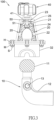
Fig. 3 shows that the hitch ball is to be accommodated in the holder of the coupler assembly of the present invention; -
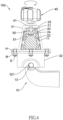
Fig. 4 shows that the hitch ball is accommodated in the holder of the coupler assembly of the present invention, the knob is rotated to lift the holder to securely hold the hitch ball; -
Fig. 5 is another angle of view ofFig. 3 , wherein one of two lugs is connected to the first part of the coupler; -
Fig. 6 is another angle of view ofFig. 4 , wherein the coupler is lowered when the holder is lifted, and the two protrusions are accommodated in the notches of the second part of the coupler; -
Fig. 7 shows the second part of the coupler and the hitch ball; -
Fig. 8 illustrates the hitch ball is held in the holder; -
Fig. 9 is a perspective view to show a second embodiment of the coupler assembly of the present invention; -
Fig. 10 shows a partial cross sectional view of second embodiment of the coupler assembly of the present invention, wherein the lever is not yet pivoted downward, and -
Fig. 11 shows a partial cross sectional view of second embodiment of the coupler assembly of the present invention, wherein the lever is pivoted downward. - Referring to
Figs. 1 to 4 , thecoupler assembly 100 of the present invention is used to be detachably connected to aball mount 10 that includes ahitch ball 11 and N -shaped shank 12 which is connected to a vehicle (not shown). Twoprotrusions 13 extend from two sides of theshank 12 of theball mount 10. - The
coupler assembly 100 of the present invention comprises aholder 20, acoupler 30, aknob 40 and apin 50. Thecoupler 30 includes twolugs 311 extending therefrom so as to be connected to a bike rack (not shown). Thecoupler 30 is a bell-shaped coupler and is mounted to theholder 20 which is removably accommodated in thecoupler 30. - The
holder 20 includes three pieces or four pieces which are assembled to form theholder 20. Each piece has aU-shaped recess 21 defined through the top thereof. Theholder 20 includes aroom 22 formed therein so as to accommodate thehitch ball 11 of theball mount 10 in theroom 22. Atube 23 extends from the top of theholder 20 and co-axially communicates with the fourrespective U-shaped recesses 21 when the four pieces are assembled with each other. Specifically, thetube 23 is composed of four curved parts respectively extending from the top of the four pieces of theholder 20. When the four pieces are assembled with each other, the four curved parts are assembled to form thetube 23. Thepin 50 extends through the fourrespective U-shaped recesses 21 and thetube 23 via theroom 22, and thepin 50 is threadedly connected to theknob 40 which is located on the top of thecoupler 30. Specifically, ascrew 401 extends through theknob 40 from the top of theknob 40 and includes a threadedsection 402. Thescrew 401 includes a hexagonal head, and theknob 40 includes a hexagonal bore so that the hexagonal head of thescrew 401 is engaged with the hexagonal bore of theknob 40. Therefore, thescrew 401 is co-rotated with theknob 40. Thepin 50 includes a threadedhole 501 defined in the top end thereof. The threadedsection 402 of thescrew 401 is threadedly connected to the threadedhole 501 in the top end of thepin 50. When rotating theknob 40, thescrew 401 is rotated with theknob 40 and lifts thepin 50, so that theholder 20 is lifted along the cone-shaped inside of thecoupler 30, and the four pieces of theholder 20 are moved toward each other. It is noted that a section of thepin 50 is located between the fourrespective U-shaped recesses 21 of the four pieces of theholder 20. Ahead 51 of thepin 50 that is opposite to the threadedhole 501 is located in areceiving area 24 defined in the inner periphery of the fourrespective U-shaped recesses 21. Aring 25 is mounted to the outside of thetube 23 to maintain the shape of thetube 23. - The
coupler 30 includes afirst part 31 and asecond part 32 which is connected to thefirst part 31 from the underside of thefirst part 31. Thefirst part 31 includes afirst flange 312 protruding radially from the lower end thereof, and thesecond part 32 includes asecond flange 322 protruding radially from the top thereof. Each of the first andsecond flanges second flanges first part 31 to thesecond part 32. Thesecond part 32 includes twonotches 321 defined in the underside of the periphery thereof. The twonotches 321 are shaped to accommodate the twoprotrusions 13 extending from theshank 12 of theball mount 10. - The two
lugs 311 and thefirst flange 312 are welded to thefirst part 31, thesecond flange 322 is welded to thesecond part 32. By this way, the manufacturing processes are easy and convenient. Besides, thefirst flange 312 includes askirt 313 extending from the periphery of thefirst flange 312. Thesecond flange 322 is located at inside of theskirt 313. Awasher 41 is located between thetube 23 and theknob 40 to adjust the distance between theholder 20 and theknob 40. - As shown in
Figs. 3-6 , when theknob 40 is rotated, theholder 20 is lifted along the cone-shaped inside of thecoupler 30 and holds thehitch ball 11 of theball mount 10. In the meanwhile, when theholder 20 is lifted, thecoupler 30 is moved downward slightly so that theprotrusions 13 of the ball mount 10 are snugly engaged with the twonotches 321 of thesecond part 32. A pad (not shown) may be located between each pair of thenotch 321 and theprotrusion 13 to absorb vibration. - As shown in
Figs. 7 and8 , the diameter of thesecond part 32 is larger than the diameter of thehitch ball 11 so as to allow thehitch ball 11 to pass through. A recessed andcurved face 323 is formed in the outside of thesecond part 32, wherein thenotch 321 is defined through the recessed andcurved face 323. The twoprotrusions 13 slightly protrude beyond the two recessed andcurved faces 323 when the twoprotrusions 13 are engaged with thenotches 321. -
Figs. 9-11 show the second embodiment of thecoupler assembly 100A of the present invention. The second embodiment is similar to the first embodiment except that theknob 40 used in the first embodiment is replaced by thelink mechanism 60 and thelever 70 so as to cooperate with thepin 50 to lift theholder 20 to hold thehitch ball 11. - The
link mechanism 60 includes aseat 61, abra 62 and anactivator 63, wherein theseal 61 is connected to the top of thecoupler 30. Thepin 50 does not have the threadedhole 501 in the first embodiment, and instead, thepin 50 includes aslot 52 defined axially therethrough. Thelever 70 is pivotably connected to theseat 11. Thebar 62 has a first end thereof pivotably connected to atip potion 611 of theseat 61 by a pivot "R", and a second end of thebar 62 is pivotably connected to theslot 52 of thepin 50. Theactivator 63 has one of two ends thereof pivotably connected to theseat 61 and located beside the inclined side of theseat 61. Another one of the two ends of theactivator 63 is pivotably connected to thelever 70. Apress part 631 extends outward from the middle portion of theactivator 63. - As shown in
Fig. 10 , when thelever 70 is positioned upright, theactivator 63 is also positioned upright, and thehead 51 of thepin 50 is lowed at a lower portion of the receivingarea 24. Theholder 20 is not lifted and the four pieces are separated from each other, so that thehitch ball 11 is not held by theholder 20. - When the
lever 70 is pivoted downward and toward thecoupler 30 as shown inFig. 11 , theactivator 63 is pivoted downward and thepress part 631 pushes and pivots thebar 62 so that the second end of thebar 62 is pivoted upward about the pivot "R" and moved upward in theslot 52 to lift thepin 50 upward. Therefore theholder 20 is lifted to hold thehitch ball 11. In this status, thehead 51 of thepin 50 is moved to an upper portion of therecess area 24. The lifting of theholder 20 makes thehitch ball 11 be lifted slightly relative to thecoupler 30 so that the twoprotrusions 13 are engaged with the twonotches 321. Therefore, thecoupler assembly 100A is securely connected to theball mount 10. - While we have shown and described the embodiment in accordance with the present invention, it should be clear to those skilled in the art that further embodiments may be made without departing from the scope of the present invention.
Claims (15)
- A coupler assembly comprising:a holder 20, a coupler 30, a knob 40 and a pin 50, the coupler 30 having two lugs 311 extending therefrom which are adapted to be connected to a bike rack, the coupler 30 mounted to the holder 20 which is removably accommodated in the coupler 30, the pin 50 extending through the holder 20 and the coupler 30 in sequence, and being connected to the knob 40 which is located on a top of the coupler 30, the holder 20 being lifted along a cone-shaped inside of the coupler 30 and adapted to hold a hitch ball 11 of a ball mount 10 when rotating the knob 40, andthe coupler 30 including a first part 31 and a second part 32, the first part 31 including a first flange 312 protruding radially from a lower end thereof, the second part 32 including a second flange 322 protruding radially from a top thereof, each of the first and second flanges 312,322 including multiple holes "H", multiple bolts "S" extending through the multiple holes "H" of each of the first and second flanges 312,322 and connected with multiple nuts "M" to connect the first part 31 to the second part 32, the second part 32 including two notches 321 defined in an underside of a periphery thereof, the two notches 321 adapted to accommodate two protrusions 13 extending from a shank 12 of the ball mount 10.
- The coupler assembly as claimed in claim 1, wherein the two lugs 311 and the first flange 312 are welded to the first part 31, the second flange 322 is welded to the second part 32.
- The coupler assembly as claimed in claim 1, wherein a screw 401 extends through the knob 40 from a top of the knob 40, the screw 401 is co-rotated with the knob 40, the screw 401 includes a threaded section 402, the pin 50 includes a threaded hole 501 defined in a top end thereof, the threaded section 402 of the screw 401 is threadedly connected to the threaded hole 501 in the top end of the pin 50.
- The coupler assembly as claimed in claim 1, wherein the first flange 312 includes a skirt 313 extending from a periphery of the first flange 312, the second flange 322 is located at inside of the skirt 313.
- The coupler assembly as claimed in claim 1, wherein the second part 32 is adapted to accommodate the hitch ball 11 of the ball mount 10, a recessed and curved face 323 is formed in the outside of the second part 32, wherein the notch is defined through the recessed and curved face 323.
- A coupler assembly comprising:a holder 20, a coupler 30, a knob 40 and a pin 50;the holder 20 being accommodated in the coupler 30 and including four pieces which are assembled to form the holder 20, each piece having a U-shaped recess defined through a top thereof, a section of the pin 50 being located between the four respective U-shaped recesses 21 of the four pieces of the holder 20, the holder 20 including a room 22 formed therein so as to accommodate a hitch ball 11 in the room 22, a tube 23 extending from the top of the holder 20 and co-axially communicating with the four respective U-shaped recesses 21 when the four pieces are assembled with each other, the pin 50 extending through the four respective U-shaped recesses 21 and the tube 23 via the room 22, a head 51 of the pin 50 located in a receiving area 24 defined in an inner periphery of the four respective U-shaped recesses 21, a ring 25 mounted to an outside of the tube 23 to assemble the four respective tops of the four pieces;the coupler 30 including a first part 31 and a second part 32, the first part 31 having a cone-shaped inside, two lugs 311 extending from the first part 31 for being connected to a bike rack, the first part 31 includes a first flange 312 protruding radially from a lower end thereof, the second part 32 including a second flange 322 protruding radially from a top thereof, each of the first and second flanges 312,322 including multiple holes "H", multiple bolts "S" extending through the multiple holes "H" of each of the first and second flanges 312,322 and connected with multiple nuts "M" to connected the first part 31 to the second part 32, the second part 32 including two notches 321 defined in an underside of a periphery thereof, the two notches 321 adapted to accommodate two protrusions 13 extending from the shank 12 of the ball mount 10, andthe knob 40 threadedly connected to the pin 50 and located on a top of the coupler 30, the holder 20 being lifted along the cone-shaped inside of the coupler 30 and adapted to hold the hitch ball 11 of a ball mount 10 when rotating the knob 40.
- The coupler assembly as claimed in claim 6, wherein the two lugs 311 and the first flange 312 are welded to the first part 31, the second flange 322 is welded to the second part 32.
- The coupler assembly as claimed in claim 6, wherein a washer 41 is located between the tube 23 and the knob 40 to adjust a distance between the holder 20 and the knob 40.
- The coupler assembly as claimed in claim 6, wherein a screw 401 extends through the knob 40 from a top of the knob 40, the screw 401 is co-rotated with the knob 40, the screw 401 includes a threaded section 402, the pin 50 includes a threaded hole 501 defined in a top end thereof, the threaded section 402 of the screw 401 is threadedly connected to the threaded hole 501 in the top end of the pin 50.
- The coupler assembly as claimed in claim 6, wherein the first flange 312 includes a skirt 313 extending from a periphery thereof, the second flange 322 is located at inside of the skirt 313.
- The coupler assembly as claimed in claim 6, wherein the second part 32 is adapted to accommodate the hitch ball 11 of the ball mount 10, a recessed and curved face 323 is formed in the outside of the second part 32, wherein the notch is defined through the recessed and curved face 323.
- A coupler assembly comprising:a holder 20, a coupler 30, a pin 50, a link mechanism 60 and a lever 70;the holder 20 being accommodated in the coupler 30 and including four pieces which are assembled to form the holder 20, each piece having a U-shaped recess 21 defined through a top thereof, a section of the pin 50 being located between the four respective U-shaped recesses 21 of the four pieces of the holder 20, the holder 20 including a room 22 formed therein so as to accommodate a hitch ball 11 in the room 22, a tube 23 extending from the top of the holder 20 and co-axially communicating with the four respective U-shaped recesses 21 when the four pieces are assembled with each other, the pin 50 extending through the four respective U-shaped recesses 21 and the tube 23 via the room 22, a head 51 of the pin 50 located in a receiving area 24 defined in an inner periphery of the four respective U-shaped recesses 21, a ring 25 mounted to an outside of the tube 23 to assemble the four respective tops of the four pieces;the coupler 30 including a first part 31 and a second part 32, the first part 31 having a cone-shaped inside, two lugs 311 extending from the first part 31 for being connected to a bike rack, the first part 31 includes a first flange 312 protruding radially from a lower end thereof, the second part 32 including a second flange 322 protruding radially from a top thereof, each of the first and second flanges 312,322 including multiple holes "H", multiple bolts "S" extending through the multiple holes "H" of each of the first and second flanges 312,322 and connected with multiple nuts "M" to connected the first part 31 to the second part 32, the second part 32 including two notches 321 defined in an underside of a periphery thereof, the two notches 321 adapted to accommodate two protrusions 13 extending from the shank 12 of the ball mount 10, andthe lever 70 pivotably connected to the link mechanism 60 which is located on the coupler 30, the link mechanism 60 pivotably connected to the pin 50 50, when pivoting the lever 70 downward, the link mechanism 60 lifts the pin 50 upward, the pin 50 lifts the holder 20 along the cone-shaped inside of the coupler 30 and adapted to hold the hitch ball 11 of a ball mount 10.
- The coupler assembly as claimed in claim 12, wherein the link mechanism 60 includes a seat 61, a bar 62 and an activator 63, the seal is connected to the top of the coupler 30, the pin 50 includes a slot 52 defined axially therethrough, the bar 62 has a first end thereof pivotably connected to a tip potion 611 of the seat 61 by a pivot "R", and a second end of the bar 62 is pivotably connected to the slot 52 of the pin 50, the activator 63 has one of two ends thereof pivotably connected to the seat 61, another one of the two ends of the activator 63 is pivotably connected to the lever 70, a press part 631 extends outward from a middle portion of the activator 63, when the lever 70 is pivoted downward toward the coupler 30, the press part 631 of the activator 63 pushes and pivots the bar 62 to lift the pin 50 upward so that the holder 20 is lifted along the cone-shaped inside of the coupler 30.
- The coupler assembly as claimed in claim 12, wherein the first flange 312 includes a skirt 313 extending from a periphery thereof, the second flange 322 is located at inside of the skirt 313.
- The coupler assembly as claimed in claim 12, wherein the two lugs 311 and the first flange 312 are welded to the first part 31, the second flange 322 is welded to the second part 32.
Applications Claiming Priority (1)
| Application Number | Priority Date | Filing Date | Title |
|---|---|---|---|
| TW110132031A TWI778769B (en) | 2021-08-30 | 2021-08-30 | Clamping and Fixing Structure for Trailer Ball |
Publications (2)
| Publication Number | Publication Date |
|---|---|
| EP4169747A2 true EP4169747A2 (en) | 2023-04-26 |
| EP4169747A3 EP4169747A3 (en) | 2023-11-01 |
Family
ID=83151809
Family Applications (1)
| Application Number | Title | Priority Date | Filing Date |
|---|---|---|---|
| EP22192516.7A Pending EP4169747A3 (en) | 2021-08-30 | 2022-08-27 | Coupler assembly for ball mount |
Country Status (3)
| Country | Link |
|---|---|
| EP (1) | EP4169747A3 (en) |
| CN (1) | CN115723678B (en) |
| TW (1) | TWI778769B (en) |
Families Citing this family (1)
| Publication number | Priority date | Publication date | Assignee | Title |
|---|---|---|---|---|
| TWI879260B (en) * | 2023-11-27 | 2025-04-01 | 高鐵工業股份有限公司 | Carrying frame ball clamp structure |
Family Cites Families (11)
| Publication number | Priority date | Publication date | Assignee | Title |
|---|---|---|---|---|
| DE2410169C3 (en) * | 1974-03-02 | 1980-09-25 | Oris-Metallbau Kg Hans Riehle, 7141 Moeglingen | Trailer coupling for vehicles |
| DK0666197T3 (en) * | 1994-02-04 | 2000-05-08 | Spinder Products Bv | Bicycle holder with a clutch device for placement on a towbar of a motor vehicle |
| FR2775943B1 (en) * | 1998-03-16 | 2000-05-19 | Fiol Vitansel | DEVICE FOR ATTACHING AND ATTACHING ITEM SUPPORT PLATFORM TO HITCH BALLS |
| US20020070529A1 (en) * | 2000-12-11 | 2002-06-13 | Dravecz Daniel Louis | Alignment device for a trailer hitch |
| CN201009697Y (en) * | 2007-03-06 | 2008-01-23 | 高铁工业股份有限公司 | Ball clamping type fixture for vehicle tail end vehicle carrying frame |
| TW200833541A (en) * | 2008-04-10 | 2008-08-16 | King Rack Ind Co Ltd | Tightening device used in ball clip of bike rack positioned at car rear |
| CN201511888U (en) * | 2009-09-30 | 2010-06-23 | 高铁工业股份有限公司 | Clamping anti-swing structure for bicycle carrying rack |
| US9738127B2 (en) * | 2012-04-18 | 2017-08-22 | Horizon Global Americas Inc. | Adjustable height gooseneck coupler |
| DE102014109134A1 (en) * | 2014-06-30 | 2015-12-31 | Scambia Holdings Cyprus Limited | Towing hitch and load carrier device for a trailer hitch |
| CN204472705U (en) * | 2015-03-18 | 2015-07-15 | 宁波晨帆汽车附件有限公司 | Tow ball latching device |
| TWI606944B (en) * | 2016-09-30 | 2017-12-01 | King Rack Industrial Co Ltd | Clip ball type clamping structure |
-
2021
- 2021-08-30 TW TW110132031A patent/TWI778769B/en active
-
2022
- 2022-08-27 EP EP22192516.7A patent/EP4169747A3/en active Pending
- 2022-08-29 CN CN202211042488.5A patent/CN115723678B/en active Active
Also Published As
| Publication number | Publication date |
|---|---|
| EP4169747A3 (en) | 2023-11-01 |
| CN115723678B (en) | 2025-05-16 |
| TWI778769B (en) | 2022-09-21 |
| CN115723678A (en) | 2023-03-03 |
| TW202308864A (en) | 2023-03-01 |
Similar Documents
| Publication | Publication Date | Title |
|---|---|---|
| US5358269A (en) | Trailer hitch | |
| US5787548A (en) | Door damper | |
| US6234509B1 (en) | Spring return coupler | |
| US6481258B1 (en) | Removable trailer hitch ball | |
| US6902181B1 (en) | Trailer hitch having rapid adjustment | |
| US5242183A (en) | Bicycle accessory for stabilization while popping wheelees | |
| US4645224A (en) | Trailer tongue handle | |
| US20040119263A1 (en) | Drawbar clevis assembly | |
| US6612380B2 (en) | Tractor attachment for three point hitch | |
| US7334809B2 (en) | Trailer hitch assembly | |
| US20220143804A1 (en) | Pivotal structure for driving head of wrench | |
| US7048070B2 (en) | Quick coupler assembly with dual hook members | |
| US20240101403A1 (en) | Adapter for lifting a vehicle using a vehicle jack | |
| US6874583B2 (en) | Quick coupler assembly | |
| US4405148A (en) | Insert for vehicle tow bar | |
| US3700263A (en) | Hitch | |
| US8162347B2 (en) | Adjustable height fifth wheel hitch | |
| KR100835599B1 (en) | Detachable trailer towing | |
| CN210881553U (en) | Multi-stage container unmanned tractor's structure of trailing | |
| GB2393107A (en) | Juicer with an easy to assemble pivotal connection for the handle | |
| CN214450008U (en) | Light truck wheel suitable for disc brake braking system | |
| US4893785A (en) | Lifting device | |
| CA2696254C (en) | Drawpin and hitch apparatus | |
| EP4169747A3 (en) | Coupler assembly for ball mount | |
| US6471051B2 (en) | Connection element for two components, one of which is tubular |
Legal Events
| Date | Code | Title | Description |
|---|---|---|---|
| PUAI | Public reference made under article 153(3) epc to a published international application that has entered the european phase |
Free format text: ORIGINAL CODE: 0009012 |
|
| STAA | Information on the status of an ep patent application or granted ep patent |
Free format text: STATUS: THE APPLICATION HAS BEEN PUBLISHED |
|
| AK | Designated contracting states |
Kind code of ref document: A2 Designated state(s): AL AT BE BG CH CY CZ DE DK EE ES FI FR GB GR HR HU IE IS IT LI LT LU LV MC MK MT NL NO PL PT RO RS SE SI SK SM TR |
|
| PUAL | Search report despatched |
Free format text: ORIGINAL CODE: 0009013 |
|
| PUAF | Information related to the publication of a search report (a3 document) modified or deleted |
Free format text: ORIGINAL CODE: 0009199SEPU |
|
| AK | Designated contracting states |
Kind code of ref document: A3 Designated state(s): AL AT BE BG CH CY CZ DE DK EE ES FI FR GB GR HR HU IE IS IT LI LT LU LV MC MK MT NL NO PL PT RO RS SE SI SK SM TR |
|
| RIC1 | Information provided on ipc code assigned before grant |
Ipc: B60R 9/06 20060101ALI20230426BHEP Ipc: B60R 9/10 20060101ALI20230426BHEP Ipc: B60D 1/06 20060101AFI20230426BHEP |
|
| D17D | Deferred search report published (deleted) | ||
| PUAL | Search report despatched |
Free format text: ORIGINAL CODE: 0009013 |
|
| RIC1 | Information provided on ipc code assigned before grant |
Ipc: B60R 9/06 20060101ALI20230918BHEP Ipc: B60R 9/10 20060101ALI20230918BHEP Ipc: B60D 1/06 20060101AFI20230918BHEP |
|
| AK | Designated contracting states |
Kind code of ref document: A3 Designated state(s): AL AT BE BG CH CY CZ DE DK EE ES FI FR GB GR HR HU IE IS IT LI LT LU LV MC MK MT NL NO PL PT RO RS SE SI SK SM TR |
|
| STAA | Information on the status of an ep patent application or granted ep patent |
Free format text: STATUS: REQUEST FOR EXAMINATION WAS MADE |
|
| 17P | Request for examination filed |
Effective date: 20240326 |
|
| RBV | Designated contracting states (corrected) |
Designated state(s): AL AT BE BG CH CY CZ DE DK EE ES FI FR GB GR HR HU IE IS IT LI LT LU LV MC MK MT NL NO PL PT RO RS SE SI SK SM TR |
|
| STAA | Information on the status of an ep patent application or granted ep patent |
Free format text: STATUS: EXAMINATION IS IN PROGRESS |
|
| 17Q | First examination report despatched |
Effective date: 20260401 |