EP4169719A1 - Method of forming article, coated powder and article - Google Patents
Method of forming article, coated powder and article Download PDFInfo
- Publication number
- EP4169719A1 EP4169719A1 EP22198933.8A EP22198933A EP4169719A1 EP 4169719 A1 EP4169719 A1 EP 4169719A1 EP 22198933 A EP22198933 A EP 22198933A EP 4169719 A1 EP4169719 A1 EP 4169719A1
- Authority
- EP
- European Patent Office
- Prior art keywords
- cleaned
- coated
- powder
- particle
- article
- Prior art date
- Legal status (The legal status is an assumption and is not a legal conclusion. Google has not performed a legal analysis and makes no representation as to the accuracy of the status listed.)
- Withdrawn
Links
Images




Classifications
-
- B—PERFORMING OPERATIONS; TRANSPORTING
- B22—CASTING; POWDER METALLURGY
- B22F—WORKING METALLIC POWDER; MANUFACTURE OF ARTICLES FROM METALLIC POWDER; MAKING METALLIC POWDER; APPARATUS OR DEVICES SPECIALLY ADAPTED FOR METALLIC POWDER
- B22F1/00—Metallic powder; Treatment of metallic powder, e.g. to facilitate working or to improve properties
- B22F1/14—Treatment of metallic powder
-
- B—PERFORMING OPERATIONS; TRANSPORTING
- B22—CASTING; POWDER METALLURGY
- B22F—WORKING METALLIC POWDER; MANUFACTURE OF ARTICLES FROM METALLIC POWDER; MAKING METALLIC POWDER; APPARATUS OR DEVICES SPECIALLY ADAPTED FOR METALLIC POWDER
- B22F1/00—Metallic powder; Treatment of metallic powder, e.g. to facilitate working or to improve properties
- B22F1/16—Metallic particles coated with a non-metal
-
- B—PERFORMING OPERATIONS; TRANSPORTING
- B22—CASTING; POWDER METALLURGY
- B22F—WORKING METALLIC POWDER; MANUFACTURE OF ARTICLES FROM METALLIC POWDER; MAKING METALLIC POWDER; APPARATUS OR DEVICES SPECIALLY ADAPTED FOR METALLIC POWDER
- B22F1/00—Metallic powder; Treatment of metallic powder, e.g. to facilitate working or to improve properties
- B22F1/17—Metallic particles coated with metal
-
- B—PERFORMING OPERATIONS; TRANSPORTING
- B22—CASTING; POWDER METALLURGY
- B22F—WORKING METALLIC POWDER; MANUFACTURE OF ARTICLES FROM METALLIC POWDER; MAKING METALLIC POWDER; APPARATUS OR DEVICES SPECIALLY ADAPTED FOR METALLIC POWDER
- B22F3/00—Manufacture of workpieces or articles from metallic powder characterised by the manner of compacting or sintering; Apparatus specially adapted therefor ; Presses and furnaces
- B22F3/12—Both compacting and sintering
- B22F3/14—Both compacting and sintering simultaneously
- B22F3/15—Hot isostatic pressing
-
- B—PERFORMING OPERATIONS; TRANSPORTING
- B33—ADDITIVE MANUFACTURING TECHNOLOGY
- B33Y—ADDITIVE MANUFACTURING, i.e. MANUFACTURING OF THREE-DIMENSIONAL [3D] OBJECTS BY ADDITIVE DEPOSITION, ADDITIVE AGGLOMERATION OR ADDITIVE LAYERING, e.g. BY 3D PRINTING, STEREOLITHOGRAPHY OR SELECTIVE LASER SINTERING
- B33Y70/00—Materials specially adapted for additive manufacturing
-
- C—CHEMISTRY; METALLURGY
- C22—METALLURGY; FERROUS OR NON-FERROUS ALLOYS; TREATMENT OF ALLOYS OR NON-FERROUS METALS
- C22C—ALLOYS
- C22C33/00—Making ferrous alloys
- C22C33/02—Making ferrous alloys by powder metallurgy
- C22C33/0257—Making ferrous alloys by powder metallurgy characterised by the range of the alloying elements
-
- C—CHEMISTRY; METALLURGY
- C23—COATING METALLIC MATERIAL; COATING MATERIAL WITH METALLIC MATERIAL; CHEMICAL SURFACE TREATMENT; DIFFUSION TREATMENT OF METALLIC MATERIAL; COATING BY VACUUM EVAPORATION, BY SPUTTERING, BY ION IMPLANTATION OR BY CHEMICAL VAPOUR DEPOSITION, IN GENERAL; INHIBITING CORROSION OF METALLIC MATERIAL OR INCRUSTATION IN GENERAL
- C23C—COATING METALLIC MATERIAL; COATING MATERIAL WITH METALLIC MATERIAL; SURFACE TREATMENT OF METALLIC MATERIAL BY DIFFUSION INTO THE SURFACE, BY CHEMICAL CONVERSION OR SUBSTITUTION; COATING BY VACUUM EVAPORATION, BY SPUTTERING, BY ION IMPLANTATION OR BY CHEMICAL VAPOUR DEPOSITION, IN GENERAL
- C23C14/00—Coating by vacuum evaporation, by sputtering or by ion implantation of the coating forming material
- C23C14/02—Pretreatment of the material to be coated
- C23C14/021—Cleaning or etching treatments
- C23C14/022—Cleaning or etching treatments by means of bombardment with energetic particles or radiation
-
- C—CHEMISTRY; METALLURGY
- C23—COATING METALLIC MATERIAL; COATING MATERIAL WITH METALLIC MATERIAL; CHEMICAL SURFACE TREATMENT; DIFFUSION TREATMENT OF METALLIC MATERIAL; COATING BY VACUUM EVAPORATION, BY SPUTTERING, BY ION IMPLANTATION OR BY CHEMICAL VAPOUR DEPOSITION, IN GENERAL; INHIBITING CORROSION OF METALLIC MATERIAL OR INCRUSTATION IN GENERAL
- C23C—COATING METALLIC MATERIAL; COATING MATERIAL WITH METALLIC MATERIAL; SURFACE TREATMENT OF METALLIC MATERIAL BY DIFFUSION INTO THE SURFACE, BY CHEMICAL CONVERSION OR SUBSTITUTION; COATING BY VACUUM EVAPORATION, BY SPUTTERING, BY ION IMPLANTATION OR BY CHEMICAL VAPOUR DEPOSITION, IN GENERAL
- C23C14/00—Coating by vacuum evaporation, by sputtering or by ion implantation of the coating forming material
- C23C14/06—Coating by vacuum evaporation, by sputtering or by ion implantation of the coating forming material characterised by the coating material
- C23C14/14—Metallic material, boron or silicon
- C23C14/16—Metallic material, boron or silicon on metallic substrates or on substrates of boron or silicon
-
- C—CHEMISTRY; METALLURGY
- C23—COATING METALLIC MATERIAL; COATING MATERIAL WITH METALLIC MATERIAL; CHEMICAL SURFACE TREATMENT; DIFFUSION TREATMENT OF METALLIC MATERIAL; COATING BY VACUUM EVAPORATION, BY SPUTTERING, BY ION IMPLANTATION OR BY CHEMICAL VAPOUR DEPOSITION, IN GENERAL; INHIBITING CORROSION OF METALLIC MATERIAL OR INCRUSTATION IN GENERAL
- C23C—COATING METALLIC MATERIAL; COATING MATERIAL WITH METALLIC MATERIAL; SURFACE TREATMENT OF METALLIC MATERIAL BY DIFFUSION INTO THE SURFACE, BY CHEMICAL CONVERSION OR SUBSTITUTION; COATING BY VACUUM EVAPORATION, BY SPUTTERING, BY ION IMPLANTATION OR BY CHEMICAL VAPOUR DEPOSITION, IN GENERAL
- C23C14/00—Coating by vacuum evaporation, by sputtering or by ion implantation of the coating forming material
- C23C14/22—Coating by vacuum evaporation, by sputtering or by ion implantation of the coating forming material characterised by the process of coating
- C23C14/223—Coating by vacuum evaporation, by sputtering or by ion implantation of the coating forming material characterised by the process of coating specially adapted for coating particles
-
- C—CHEMISTRY; METALLURGY
- C23—COATING METALLIC MATERIAL; COATING MATERIAL WITH METALLIC MATERIAL; CHEMICAL SURFACE TREATMENT; DIFFUSION TREATMENT OF METALLIC MATERIAL; COATING BY VACUUM EVAPORATION, BY SPUTTERING, BY ION IMPLANTATION OR BY CHEMICAL VAPOUR DEPOSITION, IN GENERAL; INHIBITING CORROSION OF METALLIC MATERIAL OR INCRUSTATION IN GENERAL
- C23C—COATING METALLIC MATERIAL; COATING MATERIAL WITH METALLIC MATERIAL; SURFACE TREATMENT OF METALLIC MATERIAL BY DIFFUSION INTO THE SURFACE, BY CHEMICAL CONVERSION OR SUBSTITUTION; COATING BY VACUUM EVAPORATION, BY SPUTTERING, BY ION IMPLANTATION OR BY CHEMICAL VAPOUR DEPOSITION, IN GENERAL
- C23C16/00—Chemical coating by decomposition of gaseous compounds, without leaving reaction products of surface material in the coating, i.e. chemical vapour deposition [CVD] processes
- C23C16/02—Pretreatment of the material to be coated
- C23C16/0227—Pretreatment of the material to be coated by cleaning or etching
- C23C16/0245—Pretreatment of the material to be coated by cleaning or etching by etching with a plasma
-
- C—CHEMISTRY; METALLURGY
- C23—COATING METALLIC MATERIAL; COATING MATERIAL WITH METALLIC MATERIAL; CHEMICAL SURFACE TREATMENT; DIFFUSION TREATMENT OF METALLIC MATERIAL; COATING BY VACUUM EVAPORATION, BY SPUTTERING, BY ION IMPLANTATION OR BY CHEMICAL VAPOUR DEPOSITION, IN GENERAL; INHIBITING CORROSION OF METALLIC MATERIAL OR INCRUSTATION IN GENERAL
- C23C—COATING METALLIC MATERIAL; COATING MATERIAL WITH METALLIC MATERIAL; SURFACE TREATMENT OF METALLIC MATERIAL BY DIFFUSION INTO THE SURFACE, BY CHEMICAL CONVERSION OR SUBSTITUTION; COATING BY VACUUM EVAPORATION, BY SPUTTERING, BY ION IMPLANTATION OR BY CHEMICAL VAPOUR DEPOSITION, IN GENERAL
- C23C16/00—Chemical coating by decomposition of gaseous compounds, without leaving reaction products of surface material in the coating, i.e. chemical vapour deposition [CVD] processes
- C23C16/06—Chemical coating by decomposition of gaseous compounds, without leaving reaction products of surface material in the coating, i.e. chemical vapour deposition [CVD] processes characterised by the deposition of metallic material
-
- C—CHEMISTRY; METALLURGY
- C23—COATING METALLIC MATERIAL; COATING MATERIAL WITH METALLIC MATERIAL; CHEMICAL SURFACE TREATMENT; DIFFUSION TREATMENT OF METALLIC MATERIAL; COATING BY VACUUM EVAPORATION, BY SPUTTERING, BY ION IMPLANTATION OR BY CHEMICAL VAPOUR DEPOSITION, IN GENERAL; INHIBITING CORROSION OF METALLIC MATERIAL OR INCRUSTATION IN GENERAL
- C23C—COATING METALLIC MATERIAL; COATING MATERIAL WITH METALLIC MATERIAL; SURFACE TREATMENT OF METALLIC MATERIAL BY DIFFUSION INTO THE SURFACE, BY CHEMICAL CONVERSION OR SUBSTITUTION; COATING BY VACUUM EVAPORATION, BY SPUTTERING, BY ION IMPLANTATION OR BY CHEMICAL VAPOUR DEPOSITION, IN GENERAL
- C23C16/00—Chemical coating by decomposition of gaseous compounds, without leaving reaction products of surface material in the coating, i.e. chemical vapour deposition [CVD] processes
- C23C16/44—Chemical coating by decomposition of gaseous compounds, without leaving reaction products of surface material in the coating, i.e. chemical vapour deposition [CVD] processes characterised by the method of coating
- C23C16/4417—Methods specially adapted for coating powder
-
- C—CHEMISTRY; METALLURGY
- C23—COATING METALLIC MATERIAL; COATING MATERIAL WITH METALLIC MATERIAL; CHEMICAL SURFACE TREATMENT; DIFFUSION TREATMENT OF METALLIC MATERIAL; COATING BY VACUUM EVAPORATION, BY SPUTTERING, BY ION IMPLANTATION OR BY CHEMICAL VAPOUR DEPOSITION, IN GENERAL; INHIBITING CORROSION OF METALLIC MATERIAL OR INCRUSTATION IN GENERAL
- C23C—COATING METALLIC MATERIAL; COATING MATERIAL WITH METALLIC MATERIAL; SURFACE TREATMENT OF METALLIC MATERIAL BY DIFFUSION INTO THE SURFACE, BY CHEMICAL CONVERSION OR SUBSTITUTION; COATING BY VACUUM EVAPORATION, BY SPUTTERING, BY ION IMPLANTATION OR BY CHEMICAL VAPOUR DEPOSITION, IN GENERAL
- C23C18/00—Chemical coating by decomposition of either liquid compounds or solutions of the coating forming compounds, without leaving reaction products of surface material in the coating; Contact plating
- C23C18/02—Chemical coating by decomposition of either liquid compounds or solutions of the coating forming compounds, without leaving reaction products of surface material in the coating; Contact plating by thermal decomposition
- C23C18/12—Chemical coating by decomposition of either liquid compounds or solutions of the coating forming compounds, without leaving reaction products of surface material in the coating; Contact plating by thermal decomposition characterised by the deposition of inorganic material other than metallic material
- C23C18/1229—Composition of the substrate
- C23C18/1241—Metallic substrates
-
- B—PERFORMING OPERATIONS; TRANSPORTING
- B22—CASTING; POWDER METALLURGY
- B22F—WORKING METALLIC POWDER; MANUFACTURE OF ARTICLES FROM METALLIC POWDER; MAKING METALLIC POWDER; APPARATUS OR DEVICES SPECIALLY ADAPTED FOR METALLIC POWDER
- B22F2301/00—Metallic composition of the powder or its coating
- B22F2301/15—Nickel or cobalt
-
- B—PERFORMING OPERATIONS; TRANSPORTING
- B22—CASTING; POWDER METALLURGY
- B22F—WORKING METALLIC POWDER; MANUFACTURE OF ARTICLES FROM METALLIC POWDER; MAKING METALLIC POWDER; APPARATUS OR DEVICES SPECIALLY ADAPTED FOR METALLIC POWDER
- B22F2301/00—Metallic composition of the powder or its coating
- B22F2301/20—Refractory metals
-
- B—PERFORMING OPERATIONS; TRANSPORTING
- B22—CASTING; POWDER METALLURGY
- B22F—WORKING METALLIC POWDER; MANUFACTURE OF ARTICLES FROM METALLIC POWDER; MAKING METALLIC POWDER; APPARATUS OR DEVICES SPECIALLY ADAPTED FOR METALLIC POWDER
- B22F2301/00—Metallic composition of the powder or its coating
- B22F2301/35—Iron
-
- B—PERFORMING OPERATIONS; TRANSPORTING
- B22—CASTING; POWDER METALLURGY
- B22F—WORKING METALLIC POWDER; MANUFACTURE OF ARTICLES FROM METALLIC POWDER; MAKING METALLIC POWDER; APPARATUS OR DEVICES SPECIALLY ADAPTED FOR METALLIC POWDER
- B22F2998/00—Supplementary information concerning processes or compositions relating to powder metallurgy
-
- B—PERFORMING OPERATIONS; TRANSPORTING
- B22—CASTING; POWDER METALLURGY
- B22F—WORKING METALLIC POWDER; MANUFACTURE OF ARTICLES FROM METALLIC POWDER; MAKING METALLIC POWDER; APPARATUS OR DEVICES SPECIALLY ADAPTED FOR METALLIC POWDER
- B22F2998/00—Supplementary information concerning processes or compositions relating to powder metallurgy
- B22F2998/10—Processes characterised by the sequence of their steps
-
- B—PERFORMING OPERATIONS; TRANSPORTING
- B22—CASTING; POWDER METALLURGY
- B22F—WORKING METALLIC POWDER; MANUFACTURE OF ARTICLES FROM METALLIC POWDER; MAKING METALLIC POWDER; APPARATUS OR DEVICES SPECIALLY ADAPTED FOR METALLIC POWDER
- B22F2999/00—Aspects linked to processes or compositions used in powder metallurgy
-
- C—CHEMISTRY; METALLURGY
- C22—METALLURGY; FERROUS OR NON-FERROUS ALLOYS; TREATMENT OF ALLOYS OR NON-FERROUS METALS
- C22C—ALLOYS
- C22C33/00—Making ferrous alloys
- C22C33/02—Making ferrous alloys by powder metallurgy
- C22C33/0257—Making ferrous alloys by powder metallurgy characterised by the range of the alloying elements
- C22C33/0264—Making ferrous alloys by powder metallurgy characterised by the range of the alloying elements the maximum content of each alloying element not exceeding 5%
-
- C—CHEMISTRY; METALLURGY
- C22—METALLURGY; FERROUS OR NON-FERROUS ALLOYS; TREATMENT OF ALLOYS OR NON-FERROUS METALS
- C22C—ALLOYS
- C22C33/00—Making ferrous alloys
- C22C33/02—Making ferrous alloys by powder metallurgy
- C22C33/0257—Making ferrous alloys by powder metallurgy characterised by the range of the alloying elements
- C22C33/0278—Making ferrous alloys by powder metallurgy characterised by the range of the alloying elements with at least one alloying element having a minimum content above 5%
- C22C33/0285—Making ferrous alloys by powder metallurgy characterised by the range of the alloying elements with at least one alloying element having a minimum content above 5% with Cr, Co, or Ni having a minimum content higher than 5%
-
- Y—GENERAL TAGGING OF NEW TECHNOLOGICAL DEVELOPMENTS; GENERAL TAGGING OF CROSS-SECTIONAL TECHNOLOGIES SPANNING OVER SEVERAL SECTIONS OF THE IPC; TECHNICAL SUBJECTS COVERED BY FORMER USPC CROSS-REFERENCE ART COLLECTIONS [XRACs] AND DIGESTS
- Y02—TECHNOLOGIES OR APPLICATIONS FOR MITIGATION OR ADAPTATION AGAINST CLIMATE CHANGE
- Y02P—CLIMATE CHANGE MITIGATION TECHNOLOGIES IN THE PRODUCTION OR PROCESSING OF GOODS
- Y02P10/00—Technologies related to metal processing
- Y02P10/25—Process efficiency
Definitions
- the present disclosure relates to a method of forming an article, a coated powder for forming the article, and the article formed from the coated powder.
- the base powder is produced by one of an atomisation process, a plasma-rotating electrode process, a sol-gel process, and mechanical milling.
- the one or more oxides from the external surface of each base particle is removed by ion beam sputtering.
- the cleaned external surface of each cleaned particle is coated with the second material by one of physical vapour deposition, chemical vapour deposition, and electroless plating.
- each coated particle includes at least 90%, or at least 91 %, or at least 92%, or at least 93%, or at least 94%, or at least 95%, or at least 96%, or a least 97% by weight of the first material.
- Figure 1 illustrates a schematic view of a coated powder 100 for forming an article 110.
- the article 110 is formed from the coated powder 100 as a main raw material.
- the article 110 may be produced by fusion or solidification of the coated powder 100 using, for example, sintering, die pressing, additive manufacturing techniques, hot isostatic pressing (HIP), cold isostatic pressing (CIP), injection moulding, etc., or by application of heat and/or pressure.
- HIP hot isostatic pressing
- CIP cold isostatic pressing
- Figure 3 illustrates a schematic view of a base powder 120, according to an embodiment of the present disclosure.
- the method 150 includes producing the base powder 120 including a plurality of base particles 122. A schematic sectional view of each base particle 122 is shown in Figure 3 .
- the base powder 120 may be produced by one of an atomisation process, a plasma-rotating electrode process, a sol-gel process, and mechanical milling.
- Mechanical milling is used to change properties of powders, including disintegration of particle aggregates, particle shape, and particle surface characteristics.
- Mechanical milling may include a variety of techniques, such as, for example, ball milling, vibratory milling, and attrition milling.
- each cleaned particle 132 is fully covered with the second material 112 on the cleaned external surface 134 to prevent formation of any undesirable oxides on the cleaned external surface 134 of each cleaned particle 132.
- the coated particles 102 of the coated powder 100 may not need to be maintained in a protected environment during further processing/handling due to coated particles 102 being fully covered with the second material 112 on the cleaned external surface 134. This may reduce a cost and complexity of handling the coated powder 100.
Landscapes
- Chemical & Material Sciences (AREA)
- Engineering & Computer Science (AREA)
- Mechanical Engineering (AREA)
- Materials Engineering (AREA)
- Metallurgy (AREA)
- Organic Chemistry (AREA)
- Chemical Kinetics & Catalysis (AREA)
- General Chemical & Material Sciences (AREA)
- Manufacturing & Machinery (AREA)
- Physics & Mathematics (AREA)
- Inorganic Chemistry (AREA)
- Thermal Sciences (AREA)
- Plasma & Fusion (AREA)
- Other Surface Treatments For Metallic Materials (AREA)
- Powder Metallurgy (AREA)
Abstract
A method (150) of forming an article (110) is provided. The method (150) includes producing a base powder (120) including a plurality of base particles (122). Each base particle (122) includes an external surface (124) and a first material (106). The method (150) further includes removing one or more oxides (126) from the external surface (124) of each base particle (122) to form a cleaned powder (130) including a plurality of cleaned particles (132). Each cleaned particle (132) includes a cleaned external surface (134) made of the first material (106). The method (150) further includes coating the cleaned external surface (134) of each cleaned particle (132) with a second material (112) having a greater oxidation resistance than the first material (106) to form a coated powder (100) including a plurality of coated particles (102). Each coated particle (102) includes an external layer (108) including the second material (112) that fully covers the cleaned external surface (134) made of the first material (106). The method (150) further includes forming the article (110) using the coated powder (100).
Description
- The present disclosure relates to a method of forming an article, a coated powder for forming the article, and the article formed from the coated powder.
- Raw material for manufacturing processes, such as hot isostatic pressing (HIP), additive manufacturing, etc., involve use of powders, e.g., metallic powders. Such powders may typically be manufactured as gas atomised powders which are then used for further processing. These powders generally undergo intermediate powder handling processes, such as screening to ensure the correct powder size distribution, testing of the powder for determining chemical and physical characteristics, etc.
- Powder, especially metallic powder, typically gets oxidised during handling between the processes. Oxygen pickup on the powder is almost impossible to avoid, and the presence of oxides on the powder may negatively impact material properties (e.g., toughness and ductility) of an end product. Some powder compositions are more tolerant to oxidation (e.g., 300 series stainless steel, etc.) while other powder compositions are less tolerant (e.g., low alloy steels, etc.).
- Oxidation resistance of stainless steels is provided primarily by alloyed chromium and / or nickel. The chromium is typically present in quantities between 10-20% w/w of the alloy and the nickel between 7-9% w/w. Whilst these may have a powder form and are inherently corrosion resistant the steels may have properties that are undesirable in a finished article e.g. pressure vessel.
- Low alloy steels have 8% or lower amounts of chromium w/w and optional amounts of nickel. The low levels of alloying material mean that the steel is not resistant to corrosion.
- Current practice is to minimise or exclude oxygen at all times during manufacturing of the powder and all subsequent powder handling operations. This is achieved through various methods, such as use of air and moisture evacuation procedures, inert atmosphere gas purges, controlled atmosphere glove boxes incorporating airlocks, isolation valves, etc. Such preventative measures may introduce risk as any one failure may cause an entire batch of the powder to be contaminated, and hence, ultimately scrapped. Use of such measures also impacts the processing time of the powder and adds complexity and cost to the overall manufacturing process.
- According to a first aspect there is provided a method of forming an article. The method includes producing a base powder including a plurality of base particles. Each base particle includes an external surface and a first material consisting of a low alloy steel. The method further includes removing one or more oxides from the external surface of each base particle of the base powder to form a cleaned powder including a plurality of cleaned particles. Each cleaned particle includes a cleaned external surface made of the low alloy steel. The method further includes coating the cleaned external surface of each cleaned particle of the cleaned powder with a nickel and/or chromium second material having a greater oxidation resistance than the first material to form a coated powder including a plurality of coated particles. Each coated particle includes an external layer including the second material that fully covers the cleaned external surface made of the first material. The method further includes forming an article using the coated powder.
- Use of the coated powder including the plurality of coated particles for forming the article may eliminate the need for any preventative measures to minimise or exclude oxygen during a process of forming the article. This may reduce a cost of forming the article as well as the complexity of the overall process. The one or more oxides that may be present on the external surface of the base particles may first be removed to form the cleaned powder including the cleaned particles. Each cleaned particle may then be coated with the second material such that the second material fully covers the cleaned external surface of each cleaned particle. The second material may offer greater oxidation resistance and prevent formation of the one or more oxides on the plurality of coated particles.
- In some embodiments, the base powder is produced by one of an atomisation process, a plasma-rotating electrode process, a sol-gel process, and mechanical milling.
- In some embodiments, the one or more oxides from the external surface of each base particle is removed by ion beam sputtering.
- In some embodiments, the cleaned external surface of each cleaned particle is coated with the second material by one of physical vapour deposition, chemical vapour deposition, and electroless plating.
- In some embodiments, each coated particle includes at least 90%, or at least 91 %, or at least 92%, or at least 93%, or at least 94%, or at least 95%, or at least 96%, or a least 97% by weight of the first material.
- In some embodiments, each coated particle includes at most 3%, or at most 4%, or at most 5%, or at most 6%, or at most 7%, or at most 8%, or at most 9%, or at most 10% by weight of the second material.
- In some embodiments, the coated powder is formed into the article by a hot isostatic pressing process, such that the second material is uniformly distributed throughout a volume of the article by diffusion. The amount of second material used for coating the cleaned particles may be chosen based on a desired amount of the second material in an end composition of the article formed after the hot isostatic pressing process. The second material may then be uniformly distributed throughout the volume of the article.
- In some embodiments, the hot isostatic pressing process is carried out in a non-inert and non-vacuum environment. Use of the coated powder for forming the article may eliminate the need for any preventative measures to minimise or exclude oxygen during the hot isostatic pressing process. This may reduce a cost of forming the article as well as the complexity of the hot isostatic pressing process.
- According to a second aspect, there is provided a coated powder for forming an article. The coated powder includes a plurality of coated particles. Each coated particle includes a base body made of a first material and an external layer fully covering the base body. The external layer is made of a second material having a greater oxidation resistance than the first material.
- In some embodiments, each coated particle includes at most 3%, or at most 4%, or at most 5%, or at most 6%, or at most 7%, or at most 8%, or at most 9%, or at most 10% by weight of the second material.
- According to a third aspect, there is provided an article formed from the coated powder. The article includes each of the first material and the second material uniformly distributed throughout a volume of the article. In some embodiments the article includes at most 3%, or at most 4%, or at most 5%, or at most 6%, or at most 7%, or at most 8%, or at most 9%, or at most 10% by weight of the second material. In some embodiments the article includes at least 90%, or at least 91%, or at least 92%, or at least 93%, or at least 94%, or at least 95%, or at least 96%, or a least 97% by weight of the first material.
- The skilled person will appreciate that except where mutually exclusive, a feature or parameter described in relation to any one of the above aspects may be applied to any other aspect. Furthermore, except where mutually exclusive, any feature or parameter described herein may be applied to any aspect and/or combined with any other feature or parameter described herein.
- Embodiments will now be described by way of example only, with reference to the Figures, in which:
-
Figure 1 is a schematic view of a coated powder for forming an article, according to an embodiment of the present disclosure; -
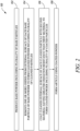
Figure 2 is flow chart illustrating a method of forming the article ofFigure 1 , according to an embodiment of the present disclosure; -
Figure 3 is a schematic view of a base powder, according to an embodiment of the present disclosure; -
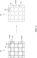
Figure 4 is a schematic view of the base powder and a cleaned powder, according to an embodiment of the present disclosure; -
Figures 5 is a schematic view of an apparatus for sputter-cleaning an external surface of base particles, according to an embodiment of the present disclosure; -
Figure 6 is a schematic view of the cleaned powder and a coated powder, according to an embodiment of the present disclosure; -
Figures 7 is a schematic view of an apparatus for coating the cleaned powder, according to an embodiment of the present disclosure; and -
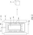
Figures 8 is a schematic view of an apparatus for forming the article, according to an embodiment of the present disclosure. - Aspects and embodiments of the present disclosure will now be discussed with reference to the accompanying figures. Further aspects and embodiments will be apparent to those skilled in the art.
-
Figure 1 illustrates a schematic view of acoated powder 100 for forming anarticle 110. In some embodiments, thearticle 110 is formed from the coatedpowder 100 as a main raw material. In some embodiments, thearticle 110 may be produced by fusion or solidification of the coatedpowder 100 using, for example, sintering, die pressing, additive manufacturing techniques, hot isostatic pressing (HIP), cold isostatic pressing (CIP), injection moulding, etc., or by application of heat and/or pressure. - In the illustrated embodiment of
Figure 1 , thearticle 110 is shown as a standard shape for illustrative purposes, however, thearticle 110 may assume any desired shape (regular or irregular) and size based on application requirements. - In some embodiments, the
coated powder 100 includes a plurality ofcoated particles 102. A schematic sectional view of eachcoated particle 102 is shown inFigure 1 . Eachcoated particle 102 incudes a base body 104 made of a first material 106 and an external layer 108 fully covering the base body 104. The first material 106 may be a low alloy steel. - In some embodiments, the external layer 108 is made of a second material 112 having a greater oxidation resistance than the first material 106. Thus, the second material 112 may protect the first material 106 from oxidation. In the present disclosure and the like, the "second material 112" having a greater oxidation resistance than the first material 106 is a metal having a greater oxidation resistance than materials used for first material 106, e.g., low alloy steel. In other words, the second material 112 is a metal having higher Gibbs free energy of oxidation reaction than the first material 106. In some circumstances the greater oxidation resistance is provided by a second material that provides a more stable oxide. In other words an oxide of the second material is less likely to shed and present virgin unoxodised material to an oxygen containing atmosphere. In some embodiments, the second material 112 is chromium and/or nickel.
- In some embodiments, each
coated particle 102 includes at most 10% by weight of the second material 112. It should be understood that the wt. percentage of each of the first material 106 and the second material 112 in thecoated particles 102 is exemplary in nature and may vary based on application requirements. In some embodiments, the wt. percentage of the first material 106 and the second material 112 may be chosen based on a desired end composition of the material of thearticle 110 to be produced. In some embodiments, thearticle 110 includes each of the first material 106 and the second material 112 uniformly distributed throughout a volume of thearticle 110. In some embodiments the thickness of the coating is determined by the average size of the cleaned particles. -
Figure 2 is a flow chart illustrating anexemplary method 150 of forming an article. In some embodiments, the article may be similar to thearticle 110 shown inFigure 1 . Themethod 150 will be described with reference to thecoated powder 100 andarticle 110 ofFigure 1 andFigures 3-8 . -
Figure 3 illustrates a schematic view of abase powder 120, according to an embodiment of the present disclosure. Referring now toFigures 2 and3 , atstep 152, themethod 150 includes producing thebase powder 120 including a plurality ofbase particles 122. A schematic sectional view of eachbase particle 122 is shown inFigure 3 . In some embodiments, thebase powder 120 may be produced by one of an atomisation process, a plasma-rotating electrode process, a sol-gel process, and mechanical milling. - Generally, the atomisation process involves forcing a liquid metal placed in a distributor through a nozzle to obtain a thin jet which is dispersed in the form of particles by rapid motion of a gas or of a stream of liquid.
- Plasma rotating electrode process is a liquid metal-fed physical method to produce powders in which a liquid stream of molten metal is poured onto a rotating disk or similar shape and is broken and dispersed, under the action of centrifugal forces, into a fine powder particulate matter that subsequently solidifies in contact with a controlled atmosphere (e.g., an inert atmosphere). The metal may be melted by various energy sources, such as helium plasma.
- Mechanical milling is used to change properties of powders, including disintegration of particle aggregates, particle shape, and particle surface characteristics. Mechanical milling may include a variety of techniques, such as, for example, ball milling, vibratory milling, and attrition milling.
- Each
base particle 122 includes anexternal surface 124 and the first material 106. When producing thebase powder 120 or thebase particles 122, especially, metallic powders, using the above-mentioned techniques, there is often an unintentional oxidation of theexternal surface 124 of thebase particles 122 due to contact with oxygen in the atmosphere. Formation of one or more oxides on theexternal surface 124 during handling of thebase powder 120 may be considered an undesirable effect which opposes the formation of metallic bonds during formation of the article 110 (shown inFigure 1 ). Therefore, it may be desirable to remove the one or more oxides from theexternal surface 124 before thebase powder 120 is used for forming of the article 110 (shown inFigure 1 ). - In the illustrated embodiment of
Figure 3 , alayer 126 is schematically shown representing the one or more oxides on theexternal surface 124 of thebase particles 122. In some embodiments, the one or more oxides may fully cover theexternal surface 124 of thebase particles 122. -
Figure 4 illustrates a schematic view of thebase powder 120 and a cleanedpowder 130, according to an embodiment of the present disclosure. Referring now toFigures 2 and4 , atstep 154, themethod 150 further includes removing the one or more oxides (e.g., the layer 126) from theexternal surface 124 of eachbase particle 122 of thebase powder 120 to form the cleanedpowder 130 including a plurality of cleanedparticles 132. A schematic sectional view of eachbase particle 122 and each cleanedparticle 132 is shown inFigure 4 . Each cleanedparticle 132 includes a cleanedexternal surface 134 made of the first material 106. In other words, each cleanedparticle 132 includes the base body 104 and the cleanedexternal surface 134 made entirely of the first material 106. The cleanedexternal surfaces 134 of the cleanedparticles 132 may be free from the one or more oxides (e.g., the layer 126) present on theexternal surface 124 of eachbase particle 122. - In some embodiments, the one or more oxides (e.g., the layer 126) from the
external surface 124 of eachbase particle 122 is removed by ion beam sputtering.Figure 5 illustrates a schematic view of anexemplary apparatus 140 for sputter-cleaning theexternal surface 124 of thebase particles 122 using ion beam sputtering. Generally, the term ion beam sputtering refers to an "atomistic" process in which neutral, or charged particles (atoms or molecules) are ejected from a surface of a target material through bombardment with energetic particles. A schematic sectional view of eachbase particle 122 is shown inFigure 5 . - In some embodiments, sputter-cleaning of the
external surface 124 of thebase particles 122 is carried out in a groundedchamber 142. A plasma 144 (e.g., argon ion plasma) is maintained in the groundedchamber 142 to create ions 146 (e.g., argon ions). In some embodiment, theplasma 144 may surround thebase particles 122 within the groundedchamber 142. The base particles 122 (or the base powder 120) are then biased negative with respect to theplasma 144 to bombard theexternal surface 124 of thebase particles 122 with theions 146. - The
ions 146 are used to clean-off the one or more oxides (e.g., the layer 126) on theexternal surface 124 of eachbase particle 122 to obtain the cleaned powder 130 (shown inFigure 4 ). In some embodiments, sputter-cleaning of theexternal surface 124 of eachbase particle 122 is carried out in a controlled environment inside the groundedchamber 142. -
Figure 6 illustrates a schematic view of the cleanedpowder 130 and thecoated powder 100, according to an embodiment of the present disclosure. Referring now toFigures 2 and6 , atstep 156, themethod 150 further includes coating the cleanedexternal surface 134 of each cleanedparticle 132 of the cleanedpowder 130 with the second material 112 having a greater oxidation resistance than the first material 106 to form thecoated powder 100 including the plurality ofcoated particles 102. A schematic sectional view of each cleanedparticle 132 and eachcoated particle 102 is shown inFigure 6 . Eachcoated particle 102 includes the external layer 108 including the second material 112 that fully covers the cleanedexternal surface 134 made of the first material 106. Thus, the second material 112 may prevent formation of one or more oxides on the cleanedexternal surface 134 of the cleanedparticles 132 during subsequent processing and handling. - In some embodiments, the cleaned
external surface 134 of each cleanedparticle 132 is coated with the second material 112 by one of physical vapour deposition (PVD), chemical vapour deposition (CVD), and electroless plating. In some embodiments, the cleanedexternal surface 134 of each cleanedparticle 132 is coated with the second material 112 in the same controlled atmosphere where the external surface 124 (shown inFigures 3-5 ) of eachbase particle 122 is cleaned to obtain the cleanedpowder 130. Thus, formation of one or more oxides on the cleanedexternal surface 134 may be avoided during handling of the cleanedpowder 130. -
Figure 7 illustrates a schematic view of anapparatus 170 for coating the cleanedexternal surface 134 of each cleanedparticle 132 of the cleaned powder 130 (shown inFigure 6 ). Specifically, theapparatus 170 allows coating the cleanedexternal surface 134 of each cleanedparticle 132 through a PVD process. PVD processes are atomic-scale deposition processes in which a material to be deposited is vaporized in the form of atoms or molecules from a solid or liquid source, i.e., acoating feedstock 172, in a vacuum or low-pressure gaseous atmosphere inside achamber 176. The atoms or molecules are then transported in the form of avapor 174 to a substrate (e.g., the cleaned powder 130) where thevapor 174 condenses to form the coated powder 100 (shown inFigure 6 ). - Referring now to
Figures 6 and7 , the material to be deposited is the second material 112 having the greater oxidation resistance than the first material 106. The substrate on which thevapor 174 gets deposited is the cleanedexternal surface 134 of each cleanedparticle 132 of the cleanedpowder 130. In some embodiments, thechamber 176 may be rotated as shown by thearrows 178 to allow each cleanedparticle 132 to be fully covered with the second material 112. In some embodiments, the amount of second material 112 to be coated on each cleaned particle 132 (e.g., a coating thickness) may be predetermined based on parameters, such as an average size of each cleanedparticle 132. In some embodiments, the cleanedparticles 132 may be coated in multiple batches of cleanedparticles 132. - In some embodiments, each cleaned
particle 132 is fully covered with the second material 112 on the cleanedexternal surface 134 to prevent formation of any undesirable oxides on the cleanedexternal surface 134 of each cleanedparticle 132. Thus, thecoated particles 102 of the coatedpowder 100 may not need to be maintained in a protected environment during further processing/handling due to coatedparticles 102 being fully covered with the second material 112 on the cleanedexternal surface 134. This may reduce a cost and complexity of handling thecoated powder 100. - Other techniques for coating the cleaned
external surface 134, such as CVD and electroless plating may also be utilized. CVD is a process in which a substrate is exposed to one or more volatile precursors (material to be deposited), which react and/or decompose on a surface of the substrate to produce a desired thin film deposit. - Electroless plating is a method of plating a metal by chemical means, in which a substrate to be plated is immersed in a reducing agent that, when catalysed by certain materials, changes metal ions to metal that forms a deposit on the substrate. It should be understood that the present disclosure is not limited to the coating techniques described above, and any know coating technique may be utilized for coating the cleaned
external surface 134 of each cleanedparticle 132, such as, for example, plasma vapor deposition, electronic sputtering, potential sputtering, magnetron sputtering, pulsed laser deposition, ion assisted deposition, gas flow sputtering, and/or the like. -
Figure 8 illustrates a schematic view of anapparatus 180 for forming thearticle 110, according to an embodiment of the present disclosure. Referring now toFigures 2 ,6 and8 , atstep 158, themethod 150 further includes forming thearticle 110 using the coated powder 160. In some embodiments, the coated powder 160 is formed into thearticle 110 by a hot isostatic pressing (HIP) process, such that the second material 112 is uniformly distributed throughout a volume of thearticle 110 by diffusion. In the illustrated example ofFigure 8 , theapparatus 180 is used to carry out the HIP process for forming thearticle 110. - As used herein, the term "hot isostatic pressing" generally refers to pressing at a temperature substantially over a generally accepted sintering temperature of a material of a melting powder involved, such that fusion of the melting powder is almost achieved and, where the pressing is from all sides at the same time, usually by a pressurized gaseous medium. This combination of simultaneous heat and pressure results in a compact achieving near full theoretical density, predominantly by plastic flow of the material of the melting powder.
- In some embodiments, the coated powder 160 may first be enclosed or canned within capsules 182 (e.g., a capsule made of mild steel), which are produced by sheet metal forming and welding. In some embodiments, each
capsule 182 deform on all surfaces during processing at high temperature and pressure. In some embodiments, eachcapsule 182 is designed to provide a fully dense end product of a desired shape. - The
capsule 182 is placed within apressure vessel 184 closed by top andbottom closures 186a, 186b. A compressor (not shown) may be adapted to pump a gas through aninlet 192 into thepressure vessel 184 while compressing the gas so as to obtain a very high gas pressure, e.g., in the order of 500-5,000 bars, in thepressure vessel 184. Thecapsule 182 is surrounded by aheat insulating member 188 which is arranged for lower heat dissipation to walls of thepressure vessel 184. -
Heating elements 190 are uniformly arranged surrounding thecapsule 182 for providing heat to thecapsule 182. Almost 100% density and bonding may be achieved between the coated particles 164 through the HIP process and the second material 112 is uniformly distributed throughout the volume of thearticle 110. In some embodiments, the amount of second material 112 may be chosen based on a composition of the second material 112 in thearticle 110. - In some embodiments, the hot isostatic pressing process may be carried out in a non-inert and non-vacuum environment. This may be achieved due to use of the coated
powder 100 having the external layer 108 (or the second material 112) coated on thecoated particles 102. Thus, the second material 112 having the greater oxidation resistance than the first material 106 may allow the hot isostatic pressing process to be carried out in the non-inert and non-vacuum environment, thereby reducing a cost and complexity of the hot isostatic pressing process. - It should be understood that the
base powder 120, thebase particles 122, the cleanedpowder 130, the cleanedparticles 132, thecoated powder 100, thecoated particles 102, and thearticle 110 are shown schematically with reference to theFigures 1-7 , and the relative size/geometry of thebase particles 122, the cleanedparticles 132, thecoated powder 100, the external layer 108, and thelayer 126 may vary based on application requirements. - It should be understood that the final desired alloy composition of the formed article may require the particle size of the powder, the thickness of the chromium and/or nickel coating, the composition of the base particles to be selected such that the final desired alloy composition is achieved. For example, where the final desired alloy composition is a low-alloy steel having a chromium and/or nickel composition below 10% by weight the composition of the low alloy steel forming the base particles will have a chromium and/or nickel composition below this value with the coating providing the additional alloying elements.
- The method and composition finds particular application where the composition of the base particles has a much lower percentage of chromium and other alloying materials. For example a low alloy steel, such as SA508, has an exemplary composition of 0.18C, 1.4Mn, 0.79Ni, 0.14Cr, 0.51Mn, 0.005V, 0.22Si, 0.024AI, 0.0123N, 0.005P, 0.003S, 0.04Cu, 0.004As, 0.008C, Balance Fe (wt%). Other grades of steels such as SA508 may have different compositons where the balance of Fe forms 90%, 91%, 92%, 93%, 94%, 95%, 96%, 97%, 98% of the base particle.
- It will be understood that the invention is not limited to the embodiments above-described and various modifications and improvements can be made without departing from the concepts described herein. Except where mutually exclusive, any of the features may be employed separately or in combination with any other features and the disclosure extends to and includes all combinations and subcombinations of one or more features described herein.
Claims (14)
- A method (150) of forming an article (110), the method (150) comprising:producing a base powder (120) comprising a plurality of base particles (122), wherein each base particle (122) of a low alloy steel (106) which comprises an external surface (124);removing one or more oxides (126) from the external surface (124) of each base particle (122) of the base powder (120) to form a cleaned powder (130) comprising a plurality of cleaned particles (132), wherein each cleaned particle (132) comprises a cleaned external surface (134);coating the cleaned external surface (134) of each cleaned particle (132) of the cleaned powder (130) with chromium and/or nickel (112) having a greater oxidation resistance than the first material (106) to form a coated powder (100) comprising a plurality of coated particles (102), wherein each coated particle (102) comprises an external layer (108) comprising the chromium and/or nickel (112) that fully covers the cleaned external surface (134) made of the low alloy steel (106); andforming the article (110) using the coated powder (100).
- The method (150) according to claim 1, wherein the base powder (120) is produced by one of an atomisation process, a plasma-rotating electrode process, a sol-gel process, and mechanical milling.
- The method (150) according to any one of the preceding claims, wherein the one or more oxides (126) from the external surface (124) of each base particle (122) is removed by ion beam sputtering.
- The method (150) according to any one of the preceding claims, wherein the cleaned external surface (134) of each cleaned particle (132) is coated with chromium and/or nickel (112) by one of physical vapour deposition, chemical vapour deposition, and electroless plating.
- The method according to any preceding claim further comprising the step of determining the average particle size of the cleaned particles and determining an average coating thickness based on the average particle size.
- The method (150) according to any one of the preceding claims, wherein each coated particle (102) comprises at least 90% by weight of the low alloy steel (106).
- The method (150) according to claim 6, wherein each coated particle (102) comprises at least 92%, or 94%, 96% by weight or the low alloy steel (106).
- The method (150) according to any one of the preceding claims, wherein each coated particle (102) comprises at most 10% by weight of the nickel and/or chromium (112).
- The method (150) according to any one of the preceding claims, wherein the coated powder (100) is formed into the article (110) by a hot isostatic pressing process, such that the second material (112) is uniformly distributed throughout a volume of the article (110) by diffusion.
- The method (150) according to claim 9, wherein the hot isostatic pressing process is carried out in a non-inert and non-vacuum environment.
- A coated powder (100) for forming an article (110), the coated powder (100) comprising:
a plurality of coated particles (102), each coated particle (102) comprising a base body (104) made of a low alloy steel (106) and an external layer (108) fully covering the base body (104), wherein the external layer (108) is made of chromium and/or nickel (112) having a greater oxidation resistance than the first material (106). - The coated powder according to claim 11, wherein each coated particle (102) comprises at least 90% by weight of the low alloy steel (106).
- The coated powder according to claim 12, wherein each coated particle (102) comprises at least 92%, or 94%, 96% by weight or the low alloy steel (106).
- The coated powder according to claim 12 or 13, wherein each coated particle (102) comprises at most 10% by weight of the chromium and/or nickel (112).
Applications Claiming Priority (1)
| Application Number | Priority Date | Filing Date | Title |
|---|---|---|---|
| GBGB2115066.9A GB202115066D0 (en) | 2021-10-21 | 2021-10-21 | Method of forming article, coated powder and article |
Publications (1)
| Publication Number | Publication Date |
|---|---|
| EP4169719A1 true EP4169719A1 (en) | 2023-04-26 |
Family
ID=78806140
Family Applications (1)
| Application Number | Title | Priority Date | Filing Date |
|---|---|---|---|
| EP22198933.8A Withdrawn EP4169719A1 (en) | 2021-10-21 | 2022-09-30 | Method of forming article, coated powder and article |
Country Status (3)
| Country | Link |
|---|---|
| US (1) | US11945030B2 (en) |
| EP (1) | EP4169719A1 (en) |
| GB (1) | GB202115066D0 (en) |
Citations (2)
| Publication number | Priority date | Publication date | Assignee | Title |
|---|---|---|---|---|
| US4985309A (en) * | 1987-08-01 | 1991-01-15 | Kawasaki Steel Corporation | Alloyed steel powder for powder metallurgy |
| WO1998042466A1 (en) * | 1997-03-24 | 1998-10-01 | Materials Innovation, Inc. | Method for making parts from particulate ferrous material |
Family Cites Families (6)
| Publication number | Priority date | Publication date | Assignee | Title |
|---|---|---|---|---|
| JPS6396227A (en) | 1986-10-14 | 1988-04-27 | Sumitomo Light Metal Ind Ltd | Manufacture of forming material from rapidly solidified aluminum alloy powder |
| US6001289A (en) | 1991-12-04 | 1999-12-14 | Materials Innovation, Inc. | Acid assisted cold welding and intermetallic formation |
| US5603815A (en) | 1994-10-04 | 1997-02-18 | Lashmore; David S. | Electrochemical fluidized bed coating of powders |
| US20180318922A1 (en) * | 2015-11-06 | 2018-11-08 | Innomaq 21, S.L. | Method for the economic manufacturing of metallic parts |
| KR102109242B1 (en) * | 2017-12-26 | 2020-05-11 | 주식회사 포스코 | Multi-layered zinc alloy plated steel material having excellent spot weldability and corrosion resistance |
| CN108746602A (en) | 2018-05-26 | 2018-11-06 | 烟台大学 | A method of preparing copper-clad iron powder using copper-containing wastewater |
-
2021
- 2021-10-21 GB GBGB2115066.9A patent/GB202115066D0/en not_active Ceased
-
2022
- 2022-09-30 US US17/957,713 patent/US11945030B2/en active Active
- 2022-09-30 EP EP22198933.8A patent/EP4169719A1/en not_active Withdrawn
Patent Citations (2)
| Publication number | Priority date | Publication date | Assignee | Title |
|---|---|---|---|---|
| US4985309A (en) * | 1987-08-01 | 1991-01-15 | Kawasaki Steel Corporation | Alloyed steel powder for powder metallurgy |
| WO1998042466A1 (en) * | 1997-03-24 | 1998-10-01 | Materials Innovation, Inc. | Method for making parts from particulate ferrous material |
Also Published As
| Publication number | Publication date |
|---|---|
| US11945030B2 (en) | 2024-04-02 |
| US20230131097A1 (en) | 2023-04-27 |
| GB202115066D0 (en) | 2021-12-08 |
Similar Documents
| Publication | Publication Date | Title |
|---|---|---|
| KR101342823B1 (en) | - coating process for manufacture or reprocessing of sputter targets and x-ray anodes | |
| EP2104753B1 (en) | Method for coating a substrate and coated product | |
| KR101342314B1 (en) | Method for coating a substrate surface and coated product | |
| US7175802B2 (en) | Refurbishing spent sputtering targets | |
| USRE40100E1 (en) | Fabrication of B/C/N/O/Si doped sputtering targets | |
| KR102511839B1 (en) | Method for treatment of metallic powder for selective laser melting | |
| CN111058004A (en) | Chromium-silicon alloy sputtering target material and preparation method thereof | |
| US8591986B1 (en) | Cold spray deposition method | |
| US11945030B2 (en) | Method of forming article, coated powder and article | |
| JP5154950B2 (en) | Method for producing targets based on silicon and zirconium by thermal spraying | |
| US20220314326A1 (en) | Method and electron beam equipment for processing powdered materials at high acceleration voltages | |
| KR102890171B1 (en) | Sputtering target and manufacturing method thereof | |
| CN109518117A (en) | A kind of metal powder applied to plasma spraying | |
| Roh et al. | Direct energy Deposition of Mo powDer prepareD by electroDe inDuction Melting gas atoMization | |
| KR20230171670A (en) | Manufacturing Method of Al-BASED AMORPHOUS ALLOY CYLINDER Target | |
| RU2405062C2 (en) | Cathode target for spraying and method of its fabrication | |
| WO1999061679A1 (en) | Target for pvd and similar processes | |
| JP2023138104A (en) | Coated member, method for manufacturing the same, and product using coated member | |
| CN121759741A (en) | CrAlCSi alloy target and its preparation method | |
| HK1123830B (en) | Coating process for manufacture or reprocessing of sputter targets and x-ray anodes | |
| HK1076843A (en) | Pt-co based sputtering targets and method of fabricating them |
Legal Events
| Date | Code | Title | Description |
|---|---|---|---|
| PUAI | Public reference made under article 153(3) epc to a published international application that has entered the european phase |
Free format text: ORIGINAL CODE: 0009012 |
|
| STAA | Information on the status of an ep patent application or granted ep patent |
Free format text: STATUS: THE APPLICATION HAS BEEN PUBLISHED |
|
| AK | Designated contracting states |
Kind code of ref document: A1 Designated state(s): AL AT BE BG CH CY CZ DE DK EE ES FI FR GB GR HR HU IE IS IT LI LT LU LV MC MK MT NL NO PL PT RO RS SE SI SK SM TR |
|
| STAA | Information on the status of an ep patent application or granted ep patent |
Free format text: STATUS: THE APPLICATION IS DEEMED TO BE WITHDRAWN |
|
| 18D | Application deemed to be withdrawn |
Effective date: 20231027 |