EP4169459A1 - Surgical instrument for transmitting torque - Google Patents
Surgical instrument for transmitting torque Download PDFInfo
- Publication number
- EP4169459A1 EP4169459A1 EP21203378.1A EP21203378A EP4169459A1 EP 4169459 A1 EP4169459 A1 EP 4169459A1 EP 21203378 A EP21203378 A EP 21203378A EP 4169459 A1 EP4169459 A1 EP 4169459A1
- Authority
- EP
- European Patent Office
- Prior art keywords
- torque
- surgical instrument
- transmitting elements
- torque transmitting
- alignment member
- Prior art date
- Legal status (The legal status is an assumption and is not a legal conclusion. Google has not performed a legal analysis and makes no representation as to the accuracy of the status listed.)
- Pending
Links
- 239000013013 elastic material Substances 0.000 claims abstract description 11
- 230000008878 coupling Effects 0.000 claims description 68
- 238000010168 coupling process Methods 0.000 claims description 68
- 238000005859 coupling reaction Methods 0.000 claims description 68
- 239000007943 implant Substances 0.000 claims description 36
- 238000005452 bending Methods 0.000 claims description 22
- 238000004519 manufacturing process Methods 0.000 claims description 14
- 239000000463 material Substances 0.000 claims description 9
- 239000000654 additive Substances 0.000 claims description 8
- 230000000996 additive effect Effects 0.000 claims description 8
- 238000005381 potential energy Methods 0.000 claims description 7
- 238000000034 method Methods 0.000 description 24
- 210000000988 bone and bone Anatomy 0.000 description 9
- 230000007246 mechanism Effects 0.000 description 9
- 229910001000 nickel titanium Inorganic materials 0.000 description 5
- 241001465754 Metazoa Species 0.000 description 3
- 230000008901 benefit Effects 0.000 description 3
- 238000005553 drilling Methods 0.000 description 3
- 238000009740 moulding (composite fabrication) Methods 0.000 description 3
- HLXZNVUGXRDIFK-UHFFFAOYSA-N nickel titanium Chemical compound [Ti].[Ti].[Ti].[Ti].[Ti].[Ti].[Ti].[Ti].[Ti].[Ti].[Ti].[Ni].[Ni].[Ni].[Ni].[Ni].[Ni].[Ni].[Ni].[Ni].[Ni].[Ni].[Ni].[Ni].[Ni] HLXZNVUGXRDIFK-UHFFFAOYSA-N 0.000 description 3
- 230000008569 process Effects 0.000 description 3
- 238000001356 surgical procedure Methods 0.000 description 3
- 238000007667 floating Methods 0.000 description 2
- 238000010438 heat treatment Methods 0.000 description 2
- 230000003993 interaction Effects 0.000 description 2
- 230000004048 modification Effects 0.000 description 2
- 238000012986 modification Methods 0.000 description 2
- 230000002441 reversible effect Effects 0.000 description 2
- 229910001285 shape-memory alloy Inorganic materials 0.000 description 2
- 238000010146 3D printing Methods 0.000 description 1
- 230000009471 action Effects 0.000 description 1
- 230000004888 barrier function Effects 0.000 description 1
- 239000011230 binding agent Substances 0.000 description 1
- 230000005540 biological transmission Effects 0.000 description 1
- 230000008859 change Effects 0.000 description 1
- 238000004140 cleaning Methods 0.000 description 1
- 230000008021 deposition Effects 0.000 description 1
- 238000010586 diagram Methods 0.000 description 1
- 230000000694 effects Effects 0.000 description 1
- 238000001125 extrusion Methods 0.000 description 1
- 239000012530 fluid Substances 0.000 description 1
- 230000004927 fusion Effects 0.000 description 1
- 238000003780 insertion Methods 0.000 description 1
- 230000037431 insertion Effects 0.000 description 1
- 238000003475 lamination Methods 0.000 description 1
- 238000003754 machining Methods 0.000 description 1
- 229910000734 martensite Inorganic materials 0.000 description 1
- 238000000465 moulding Methods 0.000 description 1
- 239000000843 powder Substances 0.000 description 1
- 238000003825 pressing Methods 0.000 description 1
- 230000004044 response Effects 0.000 description 1
- 238000000110 selective laser sintering Methods 0.000 description 1
- 239000012781 shape memory material Substances 0.000 description 1
- 230000001954 sterilising effect Effects 0.000 description 1
- 230000001225 therapeutic effect Effects 0.000 description 1
- 230000009466 transformation Effects 0.000 description 1
- 238000003466 welding Methods 0.000 description 1
Images


Classifications
-
- A—HUMAN NECESSITIES
- A61—MEDICAL OR VETERINARY SCIENCE; HYGIENE
- A61B—DIAGNOSIS; SURGERY; IDENTIFICATION
- A61B17/00—Surgical instruments, devices or methods, e.g. tourniquets
- A61B17/56—Surgical instruments or methods for treatment of bones or joints; Devices specially adapted therefor
- A61B17/58—Surgical instruments or methods for treatment of bones or joints; Devices specially adapted therefor for osteosynthesis, e.g. bone plates, screws, setting implements or the like
- A61B17/68—Internal fixation devices, including fasteners and spinal fixators, even if a part thereof projects from the skin
- A61B17/70—Spinal positioners or stabilisers ; Bone stabilisers comprising fluid filler in an implant
- A61B17/7074—Tools specially adapted for spinal fixation operations other than for bone removal or filler handling
- A61B17/7076—Tools specially adapted for spinal fixation operations other than for bone removal or filler handling for driving, positioning or assembling spinal clamps or bone anchors specially adapted for spinal fixation
- A61B17/7082—Tools specially adapted for spinal fixation operations other than for bone removal or filler handling for driving, positioning or assembling spinal clamps or bone anchors specially adapted for spinal fixation for driving, i.e. rotating, screws or screw parts specially adapted for spinal fixation, e.g. for driving polyaxial or tulip-headed screws
-
- A—HUMAN NECESSITIES
- A61—MEDICAL OR VETERINARY SCIENCE; HYGIENE
- A61B—DIAGNOSIS; SURGERY; IDENTIFICATION
- A61B17/00—Surgical instruments, devices or methods, e.g. tourniquets
- A61B17/16—Bone cutting, breaking or removal means other than saws, e.g. Osteoclasts; Drills or chisels for bones; Trepans
- A61B17/1613—Component parts
- A61B17/1631—Special drive shafts, e.g. flexible shafts
-
- A—HUMAN NECESSITIES
- A61—MEDICAL OR VETERINARY SCIENCE; HYGIENE
- A61B—DIAGNOSIS; SURGERY; IDENTIFICATION
- A61B17/00—Surgical instruments, devices or methods, e.g. tourniquets
- A61B17/16—Bone cutting, breaking or removal means other than saws, e.g. Osteoclasts; Drills or chisels for bones; Trepans
- A61B17/17—Guides or aligning means for drills, mills, pins or wires
- A61B17/1725—Guides or aligning means for drills, mills, pins or wires for applying transverse screws or pins through intramedullary nails or pins
-
- A—HUMAN NECESSITIES
- A61—MEDICAL OR VETERINARY SCIENCE; HYGIENE
- A61B—DIAGNOSIS; SURGERY; IDENTIFICATION
- A61B17/00—Surgical instruments, devices or methods, e.g. tourniquets
- A61B17/56—Surgical instruments or methods for treatment of bones or joints; Devices specially adapted therefor
- A61B17/58—Surgical instruments or methods for treatment of bones or joints; Devices specially adapted therefor for osteosynthesis, e.g. bone plates, screws, setting implements or the like
- A61B17/88—Osteosynthesis instruments; Methods or means for implanting or extracting internal or external fixation devices
- A61B17/8875—Screwdrivers, spanners or wrenches
-
- A—HUMAN NECESSITIES
- A61—MEDICAL OR VETERINARY SCIENCE; HYGIENE
- A61B—DIAGNOSIS; SURGERY; IDENTIFICATION
- A61B17/00—Surgical instruments, devices or methods, e.g. tourniquets
- A61B17/16—Bone cutting, breaking or removal means other than saws, e.g. Osteoclasts; Drills or chisels for bones; Trepans
- A61B17/1613—Component parts
- A61B17/162—Chucks or tool parts which are to be held in a chuck
-
- A—HUMAN NECESSITIES
- A61—MEDICAL OR VETERINARY SCIENCE; HYGIENE
- A61B—DIAGNOSIS; SURGERY; IDENTIFICATION
- A61B17/00—Surgical instruments, devices or methods, e.g. tourniquets
- A61B2017/00367—Details of actuation of instruments, e.g. relations between pushing buttons, or the like, and activation of the tool, working tip, or the like
- A61B2017/00398—Details of actuation of instruments, e.g. relations between pushing buttons, or the like, and activation of the tool, working tip, or the like using powered actuators, e.g. stepper motors, solenoids
-
- A—HUMAN NECESSITIES
- A61—MEDICAL OR VETERINARY SCIENCE; HYGIENE
- A61B—DIAGNOSIS; SURGERY; IDENTIFICATION
- A61B17/00—Surgical instruments, devices or methods, e.g. tourniquets
- A61B2017/00477—Coupling
Definitions
- the present disclosure generally relates to a surgical instrument for transmitting torque, a system comprising the surgical instrument and a method of using the surgical instrument.
- torque-activated tool portions such as screw-driving blades or surgical drill heads may be used.
- the screw-driving blade needs to be turned to fasten a surgical screw, and the drill head needs to be turned to drill a hole into bone.
- a surgical instrument for transmitting torque comprises a torque receiving portion at a proximal end of the surgical instrument, and a torque delivering portion at a distal end of the surgical instrument.
- the surgical instrument further comprises a flexible shaft extending between the torque receiving portion and the torque delivering portion, the flexible shaft comprising torque transmitting elements coupled in series along a longitudinal direction of the shaft such that one of the torque transmitting elements is rotationally fixed and tiltable relative to an adjacent one of the torque transmitting elements, wherein each of the torque transmitting elements comprises a through-hole.
- the surgical instrument further comprises an elongate alignment member extending through the through-holes of the torque transmitting elements, wherein the alignment member is made from a spring-elastic material.
- the torque transmitting elements may be rotationally fixed with respect to rotation around the longitudinal direction of the shaft.
- the torque transmitting elements may be coupled such that a torque applied around the longitudinal direction of the shaft at one of the torque transmitting elements is transmitted to all others of the torque transmitting elements.
- the one of the torque transmitting elements may be tiltable relative to the adjacent one of the torque transmitting elements to allow (e.g., a reversible) bending of the flexible shaft.
- the flexible shaft and the alignment member may be configured such that a relative pose between (e.g., a longitudinal axis of) the torque receiving portion and (e.g., a longitudinal axis of) the torque delivering portion can be reversibly changed.
- the alignment member may be the only component extending through the through-holes of the torque transmitting elements.
- the spring-elastic material may be a superelastic or pseudoelastic material.
- the spring-elastic material may be a shape memory material, such as a shape memory alloy.
- the spring-elastic material may be a nickel titanium alloy, for example Nitinol.
- the alignment member may be made from a single piece of material.
- the alignment member may comprise or consist of a spring wire.
- the spring wire may not form a coil. In other words, the spring wire may not be rolled, wrapped or wound.
- the spring wire may be a non-braided wire.
- the spring wire may have a substantially polygonal or circular cross-section.
- the spring wire may extend along the longitudinal direction of the shaft. In its unbiased state, the spring wire may extend in a linear direction, for example at least within each of the through-holes.
- the alignment member such as the spring wire, may be configured as a bending spring or a leaf spring.
- the alignment member may be configured to be elastically deformed when the shaft is bent.
- the alignment member may be configured to, when the shaft is bent, provide a spring force counteracting the bending of the shaft.
- the alignment member may be configured to align the torque transmitting elements in a predefined orientation relative to one another.
- the alignment member may be configured to align the torque transmitting elements such that the longitudinal direction of the shaft extends in a linear direction.
- the alignment member may be configured to, when the torque transmitting elements are in the predefined orientation relative to one another, fulfil at least one of the following criteria:
- the surgical instrument may comprise at least one recess facing the shaft, the at least one recess being formed in at least one component of the surgical instrument chosen from the torque receiving portion and the torque delivering portion.
- the alignment member may extend into the at least one recess.
- the alignment member may be configured to align the shaft in a predefined orientation relative to the at least one component.
- the alignment member may be configured to, when the shaft is in the predefined orientation relative to the at least one component, fulfil at least one of the following criteria:
- the alignment member may be configured to extend linearly when being in the state of a lowest elastic potential energy.
- the alignment member may be translationally movable along at least one direction chosen from the longitudinal direction of the shaft, a first longitudinal axis of the torque delivering portion and a second longitudinal axis of the torque receiving portion.
- the alignment member may not be attached to one or more components of the surgical instrument chosen from the torque receiving portion, the torque delivering portion and the shaft. As an example, the alignment member may loosely abut one or more of these components.
- the through-hole may extend in the longitudinal direction of the shaft.
- the through-hole may extend in a center of the torque transmitting element comprising the through-hole.
- the through-hole may have a varying diameter.
- the through-hole may have a wider diameter at one or both ends of the through hole compared with a portion of the through hole spaced apart from the respective end of the through hole.
- the wider diameter may be formed by a conical part of the through hole or a rounded surface of the torque transmitting element comprising the through-hole.
- a first one of the torque transmitting elements may be coupled to the torque receiving portion such that the first one of the torque transmitting elements is rotationally fixed and tiltable relative to the torque receiving portion.
- a second of the torque transmitting elements may be coupled to the torque delivering portion such that the second of the torque transmitting elements is rotationally fixed and tiltable relative to the torque delivering portion.
- the flexible shaft may be coupled to both the torque receiving portion and the torque delivering portion.
- a torque applied at the torque receiving portion around a longitudinal axis of the torque receiving portion may be transmitted via the torque transmitting elements to rotate the torque delivering portion around a longitudinal axis of the torque delivering portion.
- a torque applied at the torque receiving portion around a longitudinal axis of the torque receiving portion may result in a (e.g., essentially similar) torque at the torque delivering portion around the longitudinal axis of the torque delivering portion.
- the shaft may be configured to transmit torques larger than a predefined torque from the torque receiving portion to the torque delivering portion.
- At least one component chosen from the torque receiving portion and torque delivering portion may be configured to deform upon being subjected to a torque larger than the predefined torque.
- At least two of the torque transmitting elements may be manufactured, by additive manufacturing, being coupled to one another in series.
- at least one component of the surgical instrument chosen from the torque receiving portion and the torque delivering portion may be manufactured, by additive manufacturing, being coupled to one (e.g., the first or second) of the torque transmitting elements.
- the torque transmitting elements may be coupled in series such that each of the torque transmitting elements is translationally fixed, at least in the longitudinal direction of the shaft, relative to an adjacent one of the torque transmitting elements.
- One of the torque transmitting elements may comprise a female coupling feature and an adjacent one of the torque transmitting elements (e.g., adjacent to the one of the torque transmitting elements) may comprise a male coupling feature matching the female coupling feature.
- the one of the torque transmitting elements may be coupled to the adjacent one of the torque transmitting elements via the female coupling feature and the male coupling feature.
- One or more, or all, of the torque transmitting elements may comprise a female coupling feature and a male coupling feature (e.g., matching the female coupling feature).
- the torque transmitting elements may be identical to one another.
- at least one of the torque transmitting elements may comprise two female coupling features or two male coupling features.
- the two coupling features of a torque transmitting element may be rotationally offset from one another.
- the torque transmitting elements may be coupled in series by the female coupling features and the male coupling features of the torque transmitting elements.
- the female coupling feature may comprise a receptacle (e.g., for the male coupling feature of the adjacent one of the torque transmitting elements).
- the receptacle may be circumferentially (e.g., substantially) closed.
- the receptacle may be (e.g., essentially) bucket-shaped.
- the male coupling feature may comprise or consist of a protrusion sized to fit into the receptacle (e.g., of the one of the torque transmitting elements).
- the receptacle may have a polygonal inner circumference matching an outer circumference of the protrusion.
- the protrusion may have a varying thickness along the longitudinal direction of the shaft.
- a cross-section of the protrusion in a plane along the longitudinal direction of the shaft may be at least partially spherical.
- the female coupling feature may further comprise a retainment feature (e.g., a retainment lip) extending radially inwards from an inner surface of the receptacle.
- the retainment feature may be configured to prevent a decoupling of the protrusion of the adjacent one of the torque transmitting elements coupled to the receptacle.
- the receptacle may be radially enclosed by a side wall of the torque transmitting element comprising the receptacle.
- the side wall may comprise at least one through-hole connecting a space within the receptacle with a space outside the receptacle.
- a contact area of an inner surface of the receptacle may be configured to contact an outer surface of the protrusion of the adjacent one of the torque transmitting elements coupled to the receptacle, wherein the at least one through-hole may be arranged distant from the contact area.
- the torque delivering portion may comprise a screw-driving tool portion (e.g, a blade or Torx-type feature) adapted for fastening a surgical screw.
- the surgical instrument may be configured as a screw driver.
- the torque delivering portion may comprise a surgical drill head adapted for drilling holes into bone.
- the surgical instrument may be configured as a drill.
- the surgical instrument may further comprise a handle attached or coupled to the torque receiving portion.
- the handle may be configured to transmit a torque applied around the longitudinal axis of the torque receiving portion to the torque receiving portion.
- a system comprising the surgical instrument according to the first aspect.
- the system further comprises an implant placement instrument comprising a handle and a coupling portion configured to removably couple to an implant, the implant placement instrument further comprising a guiding structure configured to guide the torque delivering portion of the surgical instrument to a predefined position relative to the coupling portion, the guiding structure comprising a channel extending along a curve.
- the channel may be circumferentially closed or may have an opening along its longitudinal extension.
- the system may further comprise the implant.
- the implant may comprise two implant portions movably attachable to one another.
- the implant may further comprise a locking mechanism configured to lock the two implant portions relative to one another.
- the locking mechanism may comprise a surgical screw.
- the guiding structure may be configured to guide the torque delivering portion of the surgical instrument to a head of the surgical screw for enabling screw fastening or loosening.
- a first of the two implant portions may be an intramedullary nail and a second of the two implant portions may be a bone fastener configured to penetrate a transverse bore of the intramedullary nail to movably attach to the intramedullary nail.
- the locking mechanism may further comprise a screw thread extending along a longitudinal axis of the intramedullary nail. The surgical screw of the locking mechanism may be configured to couple with the screw thread.
- a method of using a surgical instrument comprises positioning the surgical instrument according to the first aspect such that first a longitudinal axis of the torque delivering portion is tilted relative to a longitudinal screw axis of a surgical screw.
- the method further comprises bending the flexible shaft of the surgical instrument into a bent shape in which (i) the first longitudinal axis coincides with the longitudinal screw axis and (ii) the first longitudinal axis is offset from a second longitudinal axis of the torque receiving portion, tilted relative to the second longitudinal axis or skew relative to the second longitudinal axis.
- the method further comprises coupling the torque delivering portion of the surgical instrument to a head of the surgical screw, and applying a torque at the torque receiving portion of the surgical instrument to turn the surgical screw while the flexible shaft is in the bent shape.
- the surgical instrument used in the method according the third aspect may be part of the system according to the second aspect.
- Bending the shaft may comprise at least one action chosen from bending the shaft to conform with at least a part of the curve and advancing the torque delivering portion of the surgical instrument along the guiding structure. Bending the shaft may comprise advancing the torque delivering portion of the surgical instrument along the guiding structure, thereby bending the shaft to conform with at least a part of the curve.
- the surgical screw may be part of the implant of the system according to the second aspect.
- the method in a first example may optionally further comprise implanting the implant in the patient's body before bending the flexible shaft of the surgical instrument.
- the step of implanting the implant may not be part of the method.
- the method may not involve any significant interaction with a human or animal body and in particular not comprise a surgical step.
- the instrument disclosed herein may be not be limited for use in surgery.
- the instrument disclosed herein may be usable in non-surgical scenarios.
- the instrument disclosed herein may be referred to as "torque-transmitting" instrument, instead of "surgical" instrument.
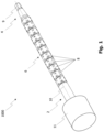
- Fig. 1 shows an embodiment of a surgical instrument 1000 in accordance with the present disclosure.
- the surgical instrument 1000 is adapted for transmitting torque.
- the surgical instrument 1000 comprises a torque receiving portion 2 at a proximal end of the surgical instrument 1000 and a torque delivering portion 4 at a distal end of the surgical instrument 1000.
- the surgical instrument 1000 further comprises a flexible shaft 6 extending between the torque receiving portion 2 and the torque delivering portion 4.
- the flexible shaft 6 comprises a plurality of torque transmitting elements 8.
- the plurality of torque transmitting elements 8 are coupled in series along a longitudinal direction 10 of the shaft 6 such that each of the torque transmitting elements 8 is rotationally fixed and tiltable relative to an adjacent one of the plurality of torque transmitting elements 8.
- the shaft 6 may comprise between 4 and 40 (e.g., between 10 and 25) torque transmitting elements 8.
- the shaft 6 may be formed by the plurality of coupled or interlinked torque transmitting elements 8.
- the shaft 6 may be flexible in that it is (e.g., reversibly) bendable. That is, an extension of the shaft may be changed from a linear extension to a curved extension and vice versa. Put differently, the shaft 6 may be reversibly bent from a first shape into a second shape from the first shape.
- the shaft 6 may be bendable by changing a relative orientation between the torque receiving portion 2 and the torque delivering portion 4.
- Each of the plurality of torque transmitting elements 8 may be tiltable relative to an adjacent one of the plurality of torque transmitting elements 8 by changing an angle between an (e.g., central, longitudinal or rotational) axis of the torque transmitting element 8 relative to an (e.g., central, longitudinal or rotational) axis of the adjacent one of the plurality of torque transmitting elements 8.
- the two axes may be part of or define at least a part of the longitudinal direction 10.
- the plurality of torque transmitting elements 8 may be rotationally fixed relative to one another such that a torque applied around the longitudinal direction 10 of the shaft 6 at one of the plurality of torque transmitting elements 8 is transmitted to all others of the plurality of torque transmitting elements 8.
- the flexible shaft 6 may be configured such that the shaft can be bent whilst permitting a transmission of torque between the plurality of torque transmitting elements 8 around the longitudinal direction 10 of the shaft 6.
- the shaft 6 may have an overall cylindrical shape.
- Each of the plurality of torque transmitting elements 8 may have an essentially cylindrical outer surface forming part of an overall cylindrical outer surface of the shaft 6.
- Each of the plurality of torque transmitting elements 8 may have the same geometry.
- Each of the plurality of torque transmitting elements 8 may be rotationally offset from a respective adjacent one of the plurality of torque transmitting elements 8 of the shaft 6.
- a first one of the plurality of torque transmitting elements 8 may be coupled to the torque receiving portion 2 such that the first of the plurality of torque transmitting elements 8 is rotationally fixed and tiltable relative to the torque receiving portion 2.
- a second one of the plurality of torque transmitting elements 8 may be coupled to the torque delivering portion 4 such that the second of the plurality of torque transmitting elements 8 is rotationally fixed and tiltable relative to the torque delivering portion 4.
- the torque receiving portion 2 may be (e.g., fixedly or non-tiltably) attached to the first of the plurality of torque transmitting elements 8 and/or the torque delivering portion 4 may be (e.g., fixedly or non-tiltably) attached to the second of the plurality of torque transmitting elements 8.
- the flexible shaft 6 may be coupled or rigidly attached to both the torque receiving portion 2 and the torque delivering portion 4. This may ensure that a torque applied at the torque receiving portion 2 around the longitudinal direction 10 is transmitted via the plurality of torque transmitting elements 8 to rotate the torque delivering portion 4 around the longitudinal direction 10.
- An input torque applied at the torque receiving portion 2 around a longitudinal axis of the torque receiving portion 2 may result in an output torque at the torque delivering portion 4 around the longitudinal axis of the torque delivering portion 4, even if the longitudinal axis of the torque receiving portion 2 is angled or skew relative to the longitudinal axis of the torque delivering portion 4.
- the torque delivering portion 4 may comprise a screw-driving tool portion 9 adapted for fastening a surgical screw.
- the surgical instrument 1000 may be configured as a screwdriver.
- the screw driving tool portion 9 may be configured as a hexagonal screw-driving portion.
- the screw driving tool portion 9 may be a hexagonal screw-driving portion in the standardized size SW4.
- Other forms of the screw-driving portion are also possible (e.g., slot-type blades, cross-type blades, square or star).
- the torque delivering portion may comprise a surgical drill head (not shown) adapted for drilling holes into bone (i.e., the surgical instrument 1000 may be configured as a drill).
- the torque receiving portion 2 may be configured to be coupled to a handle or an electrical actuator such as a motor.
- the surgical instrument 1000 may further comprise a handle 11 attached or coupled to the torque receiving portion 2.
- the handle 11 may be configured to transmit a torque applied around a longitudinal axis of the handle 11 to the torque receiving portion.
- the handle 11 may thus be rotationally fixed to the torque receiving portion 2.
- the longitudinal axis of the handle 11 may coincide with a longitudinal axis of the torque receiving portion 2.
- the shaft 6 may be configured to transmit torques larger than a predefined torque from the torque receiving portion 2 to the torque delivering portion 4, wherein at least one component chosen from the torque input portion 2 and the torque delivering portion 4 may be configured to deform upon being subjected to a torque larger than the predefined torque.
- the at least one component may be made of a material having a lower hardness than that of the plurality of torque transmitting elements 8.
- the screw driving tool portion 9 or the surgical drill head may be made of a material having a lower hardness than that of the plurality of torque transmitting elements 8.
- the screw driving tool portion 9 or the surgical drill head may be configured to deform, upon being subjected to a torque larger than the predefined torque, such that, while being further subjected to the torque larger than the predefined torque, less torque (e.g., less than a predefined minimal torque) or no torque is transferred from the deformed screw driving tool portion (e.g., to the surgical screw) or from the surgical drill head (e.g., to the bone).
- edges between lateral surfaces forming the screw driving tool portion 9 may deform such that the screw driving tool portion 9 becomes essentially cylindrical. This may avoid breaking of the surgical instrument 1000 or of a surgical implant downstream of the torque delivering portion 4 upon exerting overly large torques onto the torque receiving portion 2.
- Fig. 2a shows a cross-section of the surgical instrument of Fig. 1 along the longitudinal axis 10, and Fig. 2b shows an enlarged portion A of Fig. 2a .
- the handle 11 is not illustrated in these figures.
- each of the torque transmitting elements 8 comprises a through-hole 12.
- the through-hole 12 may extend along the longitudinal direction 10, for example in a center of the shaft 6.
- the through-hole 12 may extend in a radial center and along an axial direction of the respective torque transmitting element 8.
- the through-hole 12 may have a diameter varying along a length of the through-hole 12.
- the through-hole may have a wider diameter at the ends of the through-hole 12 compared with a central portion of the through-hole 12.
- One or both ends of the through-hole 12 may be conical.
- the width of the through-hole 12 may alternatively change non-linearly at one or both ends of the through-hole 12 along the length of the through-hole 12.
- the surgical instrument 1000 comprises an elongate alignment member 14 extending through the through-holes 12 of the plurality of torque transmitting elements 8.
- the alignment member 14 is made from a spring-elastic material.
- the alignment member 14 may be the only component extending through the through-holes 12.
- the spring-elastic material may be a superelastic or pseudoelastic material. Pseudo- or superelasticity may designate an elastic, reversible response to an applied stress, caused by a phase transformation between an austenitic and martensitic phase of the material.
- the spring-elastic material may be a shape memory alloy, for example a nickel titanium alloy such as Nitinol.
- the alignment member 14 consists of a spring wire 16.
- the spring wire 16 in this example does not form a coil, and is not rolled, wrapped or wound.
- the spring wire 16 may be a non-braided wire.
- the spring wire 16 may have a substantially circular or polygonal cross-section.
- the alignment member 14, in particular the spring wire 16, may have a diameter between 0.8 mm and 3 mm.
- the alignment member 14, in particular the spring wire 16, may have a length between 30 mm and 400 mm.
- the spring wire 16 may extend in a linear direction, for example at least within each of the through-holes 12.The spring wire may extend along the longitudinal direction 10 of the shaft 6.
- the alignment member 14 may be configured to be elastically deformed when the shaft 6 is bent, and provide a spring force counteracting the bending of the shaft 6. To this end, the alignment member 14 may be configured to align the torque transmitting elements 8 in a predefined orientation relative to one another (e.g., along the longitudinal direction 10 of the shaft 6). This configuration may enable the shaft 6 to take a predefined shape when no bending torque is applied thereto. For example, the alignment member 14 may provide a spring force aligning the plurality of torque transmitting elements 8 so that the shaft 6 extends in a linear direction (i.e., has a straight extension).
- the alignment member 14 may be configured to, when the torque transmitting elements 8 are in the predefined orientation relative to one another, fulfil at least one of the following criteria: a) the alignment member is in a state of a lowest elastic potential energy; b) the alignment member is free from a shear force; c) the alignment member is free from a bending moment; d) the alignment member is free from a tensile force.
- the surgical instrument 1000 may comprise a recess 18 facing the shaft 6.
- the recess 18 may have an essentially cylindrical shape.
- the recess 18 may be configured as a blind hole.
- the recess 18 is formed in the torque delivering portion 4 and extends along a longitudinal direction of the torque delivering portion 4.
- the recess 18 may be arranged in a radial center of the torque delivering portion 4.
- the torque receiving portion 2 may comprise a further recess configured, in the present variant, as a through-hole 20.
- the through-hole 20 may be directed towards the shaft 6 and may extend along the longitudinal direction 10 of the shaft 6.
- the through-hole 20 may be arranged in a radial center of the torque receiving portion 2 and may have an essentially cylindrical shape.
- the torque receiving portion 2 may comprise a blind hole facing the shaft 6 instead of the through-hole 20.
- the torque delivering portion 4 may comprise a through-hole instead of the recess 18.
- the alignment member 14 may extend at least partially into the torque delivering portion 4.
- the alignment member 14 may extend at least partially into the torque receiving portion 2.
- the alignment member 14 may be configured to align the shaft 6 in a predefined orientation relative to at least one component chosen from the torque delivering portion 4 and the torque receiving portion 2.
- the alignment member 14 in this case may extend at least partially into a through-hole or recess facing the shaft 6 and provided in the respective at least one component.
- this configuration may enable the shaft 6 and the respective at least one component to take a predefined shape when no external bending moment is applied thereon.
- the alignment member 14 may provide a spring force aligning the plurality of torque transmitting elements 8 and the respective at least one component such that both the shaft 6 and the respective at least one component extend in a linear direction.
- the alignment member 14 may be configured to, when the shaft 6 is in the predefined orientation relative to the at least one component, fulfil at least one of the following criteria: a) the alignment member is in a state of a lowest elastic potential energy; b) the alignment member is free from a shear force; c) the alignment member is free from a bending moment; d) the alignment member is free from a tensile force.
- the alignment member 14 may be configured to extend linearly (e.g., in a linear direction) when being in the state of a lowest elastic potential energy.
- the alignment member 14 may "stiffen" the surgical instrument 1000 such that it extends in an essentially linear direction, while providing for a selected degree of flexibility of the shaft 6.
- the surgical instrument 1000 may be more easily handled by a surgeon. For instance, aligning the surgical instrument 1000 using the handle 11 such that the torque delivering portion 4 is at in predefined position may be facilitated.
- At least two of the plurality of torque transmitting elements 8 may be manufactured, by additive manufacturing, being coupled to one another in series.
- the at least one component (chosen from the torque delivering portion 4 and the torque receiving portion 2) may be manufactured, by additive manufacturing, being coupled to one of the plurality of torque transmitting elements 8.
- the additive manufacturing may comprise or consist of three-dimensional printing, for example VAT photopolymerization, material jetting, binder jetting, powder bed fusion, material extrusion, directed energy deposition or sheet lamination.
- the additive manufacturing may comprise selective laser sintering.
- At least two of the plurality of torque transmitting elements 8 may be manufactured by at least one process selected from forming, pressing, molding and machining, and may be coupled to an adjacent one of the plurality of torque transmitting elements 8 by assembling.
- the assembled torque transmitting elements 8 may then be hardened, for example using a heat treatment.
- the at least one component (chosen from the torque delivering portion 4 and the torque receiving portion 2) may be manufactured, by the at least one process, and may be coupled to one of the plurality of torque transmitting elements 8 by assembling.
- the assembled component and torque transmitting element(s) 8 may then be hardened, for example using a heat treatment.
- the above manufacturing variants may decrease manufacturing costs of the surgical instrument 1000 and enable coupling torque transmitting elements 8 having advantageous geometrical forms as will be described further below with reference to Figs. 3a-3d .
- the alignment member 14 may be translationally movable along at least one direction chosen from the longitudinal direction 10 of the shaft 6, a first longitudinal axis of the torque delivering portion 4 and a second longitudinal axis of the torque receiving portion 2.
- the alignment member 14 may not be attached (e.g., not be welded, soldered, clamped or otherwise fastened) to one or more components of the surgical instrument 1000 chosen from the torque receiving portion 2, the torque delivering portion 4 and the shaft 6.
- the alignment member 14 in in some variants of the first option is arranged as a (e.g., at least axially) free-floating element within the surgical instrument 1000.
- the alignment member 14 may be arranged such that no tensile forces are applied thereon when bending the shaft 6.
- the alignment member 14 may be configured to be bent, but not stretched along a longitudinal axis thereof when bending the shaft 6 (e.g., when bending the shaft 6 such that the plurality of torque transmitting elements 8 are misaligned from the predefined relative orientation).
- Providing the alignment member 14 as a free-floating component may further decrease manufacturing costs, as not attachment between the alignment member 14 and other components of the surgical instrument 1000 may be required. This approach may also increase the lifetime of the surgical instrument 1000, as the alignment member 14 may be subjected to less mechanical stress compared with a configuration in which it is attached to a component of the surgical instrument 1000.
- Figs. 3a-3d show different views of the torque transmitting element 8 of the surgical instrument 1000 of Fig. 1 .
- Each of the torque transmitting elements 8 may be configured to couple to an adjacent one of the plurality of torque transmitting elements 8 of the shaft 6 such that the coupled torque transmitting elements 8 are translationally fixed relative to one another in the longitudinal direction 10 of the shaft 6.
- one torque transmitting element 8 may be configured to couple to an adjacent one of the torque transmitting elements 8 such that the two coupled torque transmitting elements 8 cannot be (e.g., non-destructively) decoupled from one another (e.g., by pulling the two torque transmitting elements 8 apart in the longitudinal direction 10).
- each of the plurality of torque transmitting elements 8 may comprise a female coupling feature 22 and a male coupling feature 24 matching the female coupling feature 22 of an adjacent one of the plurality of torque transmitting elements 8.
- the plurality of torque transmitting elements may be coupled in series by the male coupling features 24 and the female coupling features 22 of the plurality of torque transmitting elements 8.
- the female coupling feature 22 may comprise an essentially bucket-shaped receptacle 26 (e.g., for the male coupling feature 24 of an adjacent one of the plurality of torque transmitting elements 8) that is substantially closed in a circumferential direction around a longitudinal axis of the coupling feature 22.
- the male coupling feature 24 may comprise or consist of a protrusion 28 configured to fit into the receptacle 26 (e.g., of another adjacent one of the plurality of torque transmitting elements 8).
- the receptacle 26 may be configured to house the protrusion 28 of the adjacent one of the plurality of torque transmitting elements 8, and the protrusion 28 may be configured to be received by the receptacle 26 of the another adjacent one of the plurality of torque transmitting elements 8.
- Each of the plurality of torque transmitting elements 8 may have the same geometry. In this case, one may say that the protrusion 28 of a particular torque transmitting element 8 may be sized such that it theoretically fits into the receptacle 26 of that particular torque transmitting element 8.
- the receptacle 26 may have a polygonal inner circumference substantially matching an outer circumference of the protrusion 28.
- the polygonal inner circumference may have the shape of a (e.g., regular) convex polygon, for example a hexagon.
- the outer circumference of the protrusion 28 may have the shape of a (e.g., regular) convex polygon, for example a hexagon.
- the outer circumference may be a circumference around the longitudinal direction 10 of the shaft 6 and the inner circumference may be a circumference around the longitudinal direction 10 of the shaft 6.
- the outer circumference of the protrusion 28 may have a constant geometrical form varying only in size along the longitudinal direction 10.
- the inner circumference of the receptacle 26 may be rotationally offset from the outer circumference of the protrusion 28 (e.g., by 30 degrees).
- the inner circumference of the receptacle 26 may be rotationally offset from the outer circumference of the protrusion 28 such that corners of the inner circumference lie on edges of the outer circumference.
- a first torque transmitting element 8 coupled to a second first torque transmitting element 8 may be tilted along a first set of tilting directions (e.g., in a first set of tilting planes).
- a third torque transmitting element 8 coupled to the second first torque transmitting element 8 may be tilted along a second set of tilting directions (e.g., in a second set of tilting planes).
- the first set of tilting directions or planes may differ from the second set of tilting directions or planes.
- the first set of tilting planes may be rotationally offset from the second set of tilting planes by a predefined angle (e.g., 10°, 15°, 30°, 45° or 60°).
- the male coupling feature 24 and the female coupling feature 22 may be misaligned relative to one another (e.g., rotationally offset). This may lead to an adjacent torque transmitting element 8 being rotationally offset from the torque transmitting element 8 to which it is coupled.
- the receptacle 26 may have the form of a (e.g., right) prism or cylinder.
- the protrusion 28 may comprise a segment having the form of a (e.g., right) prism or cylinder with a rounded top.
- the protrusion 28 may comprise a segment having a plurality convex outer surfaces.
- the protrusion 28 may have a varying thickness along the longitudinal direction 10 of the shaft 6.
- the outer circumference mentioned above may be an outer circumference of a portion of the protrusion 28 having a highest thickness.
- a cross-section of the protrusion in a plane along the longitudinal direction 10 of the shaft 6 may be convexly rounded, for example be at least partially or overall spherical. This shape is apparent when referring to Figs. 3a and 3d , for example.
- the female coupling feature 22 may further comprise a retainment feature 30, such as a retainment lip, extending radially inwards from an inner surface of the receptacle 26.
- the retainment feature 30 may be configured to prevent a (e.g., nondestructive) decoupling of the protrusion 28 of the adjacent one of the plurality of torque transmitting elements 8 coupled to the receptacle 26.
- the retainment feature 30 acts as an axial barrier or stop, preventing a (e.g., nondestructive) decoupling of the protrusion 28 of the adjacent one of the plurality of torque transmitting elements from the receptacle 26.
- the retainment reature 30 may be configured such that an inner circumference thereof at least partially overlaps or lies within the outer circumference of the protrusion 28 of the adjacent one of the plurality of torque transmitting elements coupled to the receptacle 26.
- the receptacle 26 may be radially enclosed or formed by a side wall 32 of the torque transmitting element 8.
- the side wall 32 may have an overall cylindrical outer surface and the polygonal inner surface.
- the side wall 32 may comprise at least one through-hole 34 connecting a space within the receptacle (e.g., close to the longitudinal direction 10) with a space outside the receptacle 26 (e.g., remote from the longitudinal direction 10.
- the at least one through-hole 34 may be cylindrical, prismatic or have another geometrical form.
- the at least one through-hole 34 may extend perpendicular or, alternatively, skewed to the outer surface of the side wall 32.
- the at least one through-hole 34 may extend perpendicular or, alternatively, skewed to the inner surface of the receptacle 26.
- the at least one through-hole 34 may comprise a plurality of through-holes (e.g., arranged symmetrically on the torque transmitting element 8).
- the coupled protrusion 28 may (e.g., temporarily or permanently) contact the inner surface or wall of the receptacle 26 in a contact area 35 of the inner surface or wall (e.g., when the plurality of torque transmitting elements 8 are in the predefined orientations, when the shaft 6 extends in the linear direction and/or when the shaft is bent).
- the at least one through-hole 34 may be arranged distant from the contact area 35.
- the at least one through-hole may be arranged at a longitudinal end of the receptacle 26.
- the at least one through-hole 26 may be configured to allow a fluid medium entering (and, optionally, leaving) the receptacle 26 even if the protrusion 28 of the adjacent one of the plurality of torque transmitting elements 8 is coupled to the receptacle 26. This may help in cleaning or sterilizing the surgical instrument 1000.
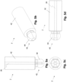
- Figs. 4a-4d show different views of a torque delivering portion 4 of the surgical instrument 1000 of Fig. 1 .
- the torque delivering portion 4 in this example comprises a hexagonal screw driving tool portion 9 at a longitudinal end thereof.
- the torque delivering portion 4 comprises a coupling feature 36 configured to couple to the second of the plurality of torque transmitting elements 8 of the shaft 6.
- the torque delivering portion 4 comprises a receptacle 37 configured to couple to the protrusion 28 of the second of the plurality of torque transmitting elements 8.
- the receptacle 37 may be configured similar to the receptacle 26 described above, and may comprise a corresponding retainment feature 38 and a corresponding at least one through-hole 40.
- the coupling feature 36 may be a male coupling feature such as the protrusion 28 described above.
- Figs. 5a-5d show different views of a torque receiving portion 2 of the surgical instrument 1000 of Fig. 1 .
- the torque receiving portion 2 in this example comprises a handle or actuator coupling portion 42 at a longitudinal end thereof.
- the coupling portion 42 may be essentially cylindrical.
- the torque receiving portion 2 comprises a coupling feature 43 configured to couple to the first of the plurality of torque transmitting elements 8 of the shaft 6.
- the torque receiving portion 2 comprises a protrusion 44 configured to couple to the receptacle 26 of the first of the plurality of torque transmitting elements 8.
- the protrusion 44 may be configured similar to the protrusion 28 described above and may have a polygonal outer circumference.
- the coupling feature 43 may be a female coupling feature such as the receptacle 26 described above.
- the shaft may comprise torque transmitting elements with two female coupling features.
- the shaft may comprise torque transmitting elements with two male coupling features.
- the shaft may comprise at least two elements selected from: (i) one or more torque transmitting elements having a male and a female coupling portion; (ii) one or more torque transmitting elements having two male coupling portions; and (iii) one or more torque transmitting elements having two female coupling portions.
- the shaft may comprise at least one torque transmitting element having different types of (e.g., male or female) coupling portions, for example one (e.g., male or female) coupling portion as described above with reference to Figs.
- torque receiving portion and the torque delivering portion each comprise a (e.g., male or female) coupling portion matching a coupling portion of an adjacent one (e.g., the first or second) of the plurality of torque transmitting elements of the shaft.
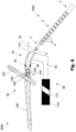
- Fig. 6 shows a system 3000 in accordance with the present disclosure.
- the system 3000 comprises the surgical instrument 1000 as described above.
- the system 3000 further comprises an implant placement instrument 88 comprising a handle 90 and a coupling portion 92 configured to removably couple to an implant.
- the implant placement instrument 88 further comprises a guiding structure 94 configured to guide the torque delivering portion 4 of the surgical instrument 1000 to a predefined position relative to the coupling portion 92.
- the guiding structure 94 comprises a channel 96 extending along a curve.
- the system 3000 may further comprise an implant 98.
- the coupling portion 92 may be configured to couple to (e.g., a corresponding coupling portion of) the implant 98.
- the implant placement instrument 88 may be configured for removably holding the implant 98, for example for positioning the coupled implant 98 at an intended location using the handle 90.
- the implant 98 may comprise two implant portions 100, 102 movably attachable to one another.
- the implant 98 may further comprise a locking mechanism 104 configured to lock the two implant portions 100, 102 relative to one another.
- the locking mechanism 104 may comprise a surgical screw 106.
- the guiding structure 94 may be configured to guide the torque delivering portion 4 of the surgical instrument 1000 to a head 108 of the surgical screw 106.
- the implant portion 100 may be an intramedullary nail and the implant portion 102 may be a bone fastener configured to penetrate a transverse bore of the intramedullary nail 100 to movably attach to the intramedullary nail 100.
- the locking mechanism 104 may further comprise a screw thread 109 extending along a longitudinal axis 110 of the intramedullary nail 100.
- the surgical screw 106 of the locking mechanism 104 may be configured to couple with the screw thread 109.
- the implant placement instrument 88 may further comprise an alignment element 110.
- the alignment element 110 may be spatially fixed relative to the coupling portion 92, and may for example be attached to the handle 90.
- the alignment element 110 may comprise an alignment hole 112 configured to align a surgical instrument (not shown) in a predefined pose relative to the coupling portion 92.
- a drill may be inserted through the alignment hole 112 and a hole may be drilled in the predefined pose. This may enable inserting the bone fastener 102 in the predefined pose relative to the intramedullary nail 100, ensuring a proper (e.g., movable) attachment between these two elements 100, 102.
- Upon fastening the screw 106 using the surgical instrument 1000 a relative movement between the bone fastener 102 and the intramedullary nail 100 may be blocked.
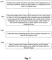
- Fig. 7 is a flow diagram of a method in accordance with the present disclosure.
- the method comprises a step 1202 of positioning the surgical instrument 1000 such that the first a longitudinal axis of the torque delivering portion 4 is tilted relative to a longitudinal screw axis (e.g., coinciding with or corresponding to the axis 90) of a surgical screw (e.g., the screw 106).
- a longitudinal screw axis e.g., coinciding with or corresponding to the axis 90
- the method further comprises a step 1204 of bending the flexible shaft 6 of the surgical instrument 1000 into a bent shape in which (i) the first longitudinal axis coincides with the longitudinal screw axis and (ii) the first longitudinal axis is offset from the second longitudinal axis of the torque receiving portion 2, tilted relative to the second longitudinal axis or skew relative to the second longitudinal axis.
- the method further comprises a step 1206 of coupling the torque delivering portion 4 of the surgical instrument 1000 to a head of the surgical screw, and a step 1208 of applying a torque at the torque receiving portion 2 of the surgical instrument 1000 to turn the surgical screw while the flexible shaft 6 is in the bent shape.
- the longitudinal axis of the torque delivering portion 4 may in an initial state of the surgical instrument 1000 correspond to the longitudinal direction 10 of the shaft 6.
- the instrument 1000 may extend in an essentially linear direction.
- the axis 90 that may coincide with the longitudinal axis of the screw 106, is tilted relative to the direction 10.
- the torque delivering portion 4 of the surgical instrument 1000 comprising the screw driving tool portion 9, must be aligned with the screw axis.
- the system may enable the surgical instrument 1000 to advance from a tilted angle relative to the screw axis of the screw 106.
- the torque delivering portion 4 of the surgical instrument 1000 (e.g., extending linearly as shown in Fig. 6 ) may be inserted into the guiding structure 94 and advanced toward the surgical screw 106.
- the surgical instrument 1000 is in a predefined shape (e.g., in case the shaft 6 is aligned by the alignment member 14), for example a linear shape as shown in Fig. 6 , the insertion of the torque delivering portion 4 into the channel 96 may be facilitated.
- the shaft 6 may be bent to follow the shape of the channel 96.
- the torque delivering portion 4 may reach the screw head 108 of the surgical screw 106.
- Torque may then be applied to the torque receiving portion 2 around a longitudinal axis thereof.
- This torque may then be transmitted by the plurality of torque transmitting elements 8 onto the torque delivering portion 4, which may thereby fasten the screw 106 along the screw thread 109.
- Fastening the screw 106 may exert a force onto the implant portion 102, thereby shifting the locking mechanism 104 into a locked configuration (e.g., locking the two implant portions 100, 102 relative to one another).
- the torque delivering portion 4 or the torque receiving portion 2 may deform, thereby preventing breakage of the surgical instrument 1000. This may avoid broken parts of the surgical instrument 1000 remaining in the channel 96 when retracting the surgical instrument 1000 therefrom.
- the method may be conducted before implanting the implant 98 in a patient's body, or after implanting the implant 98 in the patient's body.
- the method in some variants may be conducted using a cadaver or a dummy instead of a live human or animal body. In some variants, the method does not involve any substantial interaction with the human or animal body, in particular no surgical or therapeutic step.
Abstract
Description
- The present disclosure generally relates to a surgical instrument for transmitting torque, a system comprising the surgical instrument and a method of using the surgical instrument.
- In several surgical scenarios, surgical screws need to be fastened or holes need to be drilled. For this purpose, torque-activated tool portions such as screw-driving blades or surgical drill heads may be used. The screw-driving blade needs to be turned to fasten a surgical screw, and the drill head needs to be turned to drill a hole into bone.
- Commonly used surgical instruments with torque-activated tool portions are rigid and non-flexible. In certain use cases, the surgical screw or the drilling position may be hard or even impossible to reach using such rigid, non-flexible instruments. To address this issue, flexible surgical instruments have been developed that allow for an adjustment of a relative orientation between, for example, a handle of the instrument and the torque-activated tool portion by providing a bendable shaft interconnecting the handle and the torque-activated tool portion.
- Current flexible surgical instruments often suffer from one or more drawbacks. For instance, they may be hard to align relative to a position of interest, and may be hard to clean and sterilize. Known flexible surgical instruments may be prone to breaking upon exertion of high torques, potentially leading to parts of the instruments being left inside a patient's body after surgery. Still further, such known flexible instruments may be hard to manufacture, thereby increasing costs.
- There is a need for a surgical instrument for transmitting torque that solves one or more of the aforementioned or other problems.
- According to a first aspect, a surgical instrument for transmitting torque is provided. The surgical instrument comprises a torque receiving portion at a proximal end of the surgical instrument, and a torque delivering portion at a distal end of the surgical instrument. The surgical instrument further comprises a flexible shaft extending between the torque receiving portion and the torque delivering portion, the flexible shaft comprising torque transmitting elements coupled in series along a longitudinal direction of the shaft such that one of the torque transmitting elements is rotationally fixed and tiltable relative to an adjacent one of the torque transmitting elements, wherein each of the torque transmitting elements comprises a through-hole. The surgical instrument further comprises an elongate alignment member extending through the through-holes of the torque transmitting elements, wherein the alignment member is made from a spring-elastic material.
- In the surgical instrument, the torque transmitting elements may be rotationally fixed with respect to rotation around the longitudinal direction of the shaft. The torque transmitting elements may be coupled such that a torque applied around the longitudinal direction of the shaft at one of the torque transmitting elements is transmitted to all others of the torque transmitting elements.
- The one of the torque transmitting elements may be tiltable relative to the adjacent one of the torque transmitting elements to allow (e.g., a reversible) bending of the flexible shaft. The flexible shaft and the alignment member may be configured such that a relative pose between (e.g., a longitudinal axis of) the torque receiving portion and (e.g., a longitudinal axis of) the torque delivering portion can be reversibly changed. The alignment member may be the only component extending through the through-holes of the torque transmitting elements.
- The spring-elastic material may be a superelastic or pseudoelastic material. The spring-elastic material may be a shape memory material, such as a shape memory alloy. The spring-elastic material may be a nickel titanium alloy, for example Nitinol.
- The alignment member may be made from a single piece of material. The alignment member may comprise or consist of a spring wire. The spring wire may not form a coil. In other words, the spring wire may not be rolled, wrapped or wound. The spring wire may be a non-braided wire. The spring wire may have a substantially polygonal or circular cross-section. The spring wire may extend along the longitudinal direction of the shaft. In its unbiased state, the spring wire may extend in a linear direction, for example at least within each of the through-holes.
- The alignment member, such as the spring wire, may be configured as a bending spring or a leaf spring. The alignment member may be configured to be elastically deformed when the shaft is bent. The alignment member may be configured to, when the shaft is bent, provide a spring force counteracting the bending of the shaft.
- The alignment member may be configured to align the torque transmitting elements in a predefined orientation relative to one another. The alignment member may be configured to align the torque transmitting elements such that the longitudinal direction of the shaft extends in a linear direction.
- The alignment member may be configured to, when the torque transmitting elements are in the predefined orientation relative to one another, fulfil at least one of the following criteria:
- a) the alignment member is in a state of a lowest elastic potential energy;
- b) the alignment member is free from a shear force;
- c) the alignment member is free from a bending moment;
- d) the alignment member is free from a tensile force.
- The surgical instrument may comprise at least one recess facing the shaft, the at least one recess being formed in at least one component of the surgical instrument chosen from the torque receiving portion and the torque delivering portion. The alignment member may extend into the at least one recess. The alignment member may be configured to align the shaft in a predefined orientation relative to the at least one component.
- The alignment member may be configured to, when the shaft is in the predefined orientation relative to the at least one component, fulfil at least one of the following criteria:
- a) the alignment member is in a state of a lowest elastic potential energy;
- b) the alignment member is free from a shear force;
- c) the alignment member is free from a bending moment;
- d) the alignment member is free from a tensile force.
- The alignment member may be configured to extend linearly when being in the state of a lowest elastic potential energy.
- The alignment member may be translationally movable along at least one direction chosen from the longitudinal direction of the shaft, a first longitudinal axis of the torque delivering portion and a second longitudinal axis of the torque receiving portion. The alignment member may not be attached to one or more components of the surgical instrument chosen from the torque receiving portion, the torque delivering portion and the shaft. As an example, the alignment member may loosely abut one or more of these components.
- The through-hole may extend in the longitudinal direction of the shaft. The through-hole may extend in a center of the torque transmitting element comprising the through-hole. The through-hole may have a varying diameter. The through-hole may have a wider diameter at one or both ends of the through hole compared with a portion of the through hole spaced apart from the respective end of the through hole. The wider diameter may be formed by a conical part of the through hole or a rounded surface of the torque transmitting element comprising the through-hole.
- A first one of the torque transmitting elements may be coupled to the torque receiving portion such that the first one of the torque transmitting elements is rotationally fixed and tiltable relative to the torque receiving portion. A second of the torque transmitting elements may be coupled to the torque delivering portion such that the second of the torque transmitting elements is rotationally fixed and tiltable relative to the torque delivering portion. The flexible shaft may be coupled to both the torque receiving portion and the torque delivering portion. A torque applied at the torque receiving portion around a longitudinal axis of the torque receiving portion may be transmitted via the torque transmitting elements to rotate the torque delivering portion around a longitudinal axis of the torque delivering portion. A torque applied at the torque receiving portion around a longitudinal axis of the torque receiving portion may result in a (e.g., essentially similar) torque at the torque delivering portion around the longitudinal axis of the torque delivering portion.
- The shaft may be configured to transmit torques larger than a predefined torque from the torque receiving portion to the torque delivering portion. At least one component chosen from the torque receiving portion and torque delivering portion may be configured to deform upon being subjected to a torque larger than the predefined torque.
- At least two of the torque transmitting elements may be manufactured, by additive manufacturing, being coupled to one another in series. Alternatively or additionally, at least one component of the surgical instrument chosen from the torque receiving portion and the torque delivering portion may be manufactured, by additive manufacturing, being coupled to one (e.g., the first or second) of the torque transmitting elements.
- The torque transmitting elements may be coupled in series such that each of the torque transmitting elements is translationally fixed, at least in the longitudinal direction of the shaft, relative to an adjacent one of the torque transmitting elements.
- One of the torque transmitting elements may comprise a female coupling feature and an adjacent one of the torque transmitting elements (e.g., adjacent to the one of the torque transmitting elements) may comprise a male coupling feature matching the female coupling feature. The one of the torque transmitting elements may be coupled to the adjacent one of the torque transmitting elements via the female coupling feature and the male coupling feature.
- One or more, or all, of the torque transmitting elements may comprise a female coupling feature and a male coupling feature (e.g., matching the female coupling feature). The torque transmitting elements may be identical to one another. Alternatively, at least one of the torque transmitting elements may comprise two female coupling features or two male coupling features. In both variants, the two coupling features of a torque transmitting element may be rotationally offset from one another.
- The torque transmitting elements may be coupled in series by the female coupling features and the male coupling features of the torque transmitting elements.
- In a first variant, the female coupling feature may comprise a receptacle (e.g., for the male coupling feature of the adjacent one of the torque transmitting elements). The receptacle may be circumferentially (e.g., substantially) closed. The receptacle may be (e.g., essentially) bucket-shaped. The male coupling feature may comprise or consist of a protrusion sized to fit into the receptacle (e.g., of the one of the torque transmitting elements). The receptacle may have a polygonal inner circumference matching an outer circumference of the protrusion. The protrusion may have a varying thickness along the longitudinal direction of the shaft. A cross-section of the protrusion in a plane along the longitudinal direction of the shaft may be at least partially spherical. The female coupling feature may further comprise a retainment feature (e.g., a retainment lip) extending radially inwards from an inner surface of the receptacle. The retainment feature may be configured to prevent a decoupling of the protrusion of the adjacent one of the torque transmitting elements coupled to the receptacle. The receptacle may be radially enclosed by a side wall of the torque transmitting element comprising the receptacle. The side wall may comprise at least one through-hole connecting a space within the receptacle with a space outside the receptacle. A contact area of an inner surface of the receptacle may be configured to contact an outer surface of the protrusion of the adjacent one of the torque transmitting elements coupled to the receptacle, wherein the at least one through-hole may be arranged distant from the contact area.
- The torque delivering portion may comprise a screw-driving tool portion (e.g, a blade or Torx-type feature) adapted for fastening a surgical screw. The surgical instrument may be configured as a screw driver. Alternatively, the torque delivering portion may comprise a surgical drill head adapted for drilling holes into bone. The surgical instrument may be configured as a drill.
- The surgical instrument may further comprise a handle attached or coupled to the torque receiving portion. The handle may be configured to transmit a torque applied around the longitudinal axis of the torque receiving portion to the torque receiving portion.
- According to a second aspect, a system is provided. The system comprises the surgical instrument according to the first aspect. The system further comprises an implant placement instrument comprising a handle and a coupling portion configured to removably couple to an implant, the implant placement instrument further comprising a guiding structure configured to guide the torque delivering portion of the surgical instrument to a predefined position relative to the coupling portion, the guiding structure comprising a channel extending along a curve. The channel may be circumferentially closed or may have an opening along its longitudinal extension.
- The system may further comprise the implant. The implant may comprise two implant portions movably attachable to one another. The implant may further comprise a locking mechanism configured to lock the two implant portions relative to one another. The locking mechanism may comprise a surgical screw. The guiding structure may be configured to guide the torque delivering portion of the surgical instrument to a head of the surgical screw for enabling screw fastening or loosening.
- A first of the two implant portions may be an intramedullary nail and a second of the two implant portions may be a bone fastener configured to penetrate a transverse bore of the intramedullary nail to movably attach to the intramedullary nail. The locking mechanism may further comprise a screw thread extending along a longitudinal axis of the intramedullary nail. The surgical screw of the locking mechanism may be configured to couple with the screw thread.
- According to a third aspect, a method of using a surgical instrument is provided. The method comprises positioning the surgical instrument according to the first aspect such that first a longitudinal axis of the torque delivering portion is tilted relative to a longitudinal screw axis of a surgical screw. The method further comprises bending the flexible shaft of the surgical instrument into a bent shape in which (i) the first longitudinal axis coincides with the longitudinal screw axis and (ii) the first longitudinal axis is offset from a second longitudinal axis of the torque receiving portion, tilted relative to the second longitudinal axis or skew relative to the second longitudinal axis. The method further comprises coupling the torque delivering portion of the surgical instrument to a head of the surgical screw, and applying a torque at the torque receiving portion of the surgical instrument to turn the surgical screw while the flexible shaft is in the bent shape.
- The surgical instrument used in the method according the third aspect may be part of the system according to the second aspect. Bending the shaft may comprise at least one action chosen from bending the shaft to conform with at least a part of the curve and advancing the torque delivering portion of the surgical instrument along the guiding structure. Bending the shaft may comprise advancing the torque delivering portion of the surgical instrument along the guiding structure, thereby bending the shaft to conform with at least a part of the curve. The surgical screw may be part of the implant of the system according to the second aspect.
- The method in a first example may optionally further comprise implanting the implant in the patient's body before bending the flexible shaft of the surgical instrument.
- It is to be noted that the step of implanting the implant may not be part of the method. The method may not involve any significant interaction with a human or animal body and in particular not comprise a surgical step.
- The instrument disclosed herein may be not be limited for use in surgery. The instrument disclosed herein may be usable in non-surgical scenarios. In one particular variant, the instrument disclosed herein may be referred to as "torque-transmitting" instrument, instead of "surgical" instrument.
- Further details, advantages and aspects of the present disclosure will become apparent from the following embodiments taken in conjunction with the drawings, wherein:
- Fig. 1
- shows an embodiment of a surgical instrument in accordance with the present disclosure;
- Fig. 2a
- shows a longitudinal cross-section of the surgical instrument of
Fig. 1 ; - Fig. 2b
- shows an enlarged portion A of the cross-section of
Fig. 2a ; - Figs. 3a-3d
- show different views of a torque transmitting element of the surgical instrument of
Fig. 1 ; - Figs. 4a-4d
- show different views of a torque delivering portion of the surgical instrument of
Fig. 1 ; - Figs. 5a-5d
- show different views of a torque receiving portion of the surgical instrument of
Fig. 1 ; - Fig. 6
- shows a system in accordance with the present disclosure; and
- Fig. 7
- shows a method in accordance with the present disclosure.
- In the following description, exemplary embodiments of a surgical instrument, a system comprising the surgical instrument and a method of using same will be explained with reference to the drawings. The same reference numerals will be used to denote the same or similar structural features.
-
Fig. 1 shows an embodiment of asurgical instrument 1000 in accordance with the present disclosure. Thesurgical instrument 1000 is adapted for transmitting torque. Thesurgical instrument 1000 comprises atorque receiving portion 2 at a proximal end of thesurgical instrument 1000 and atorque delivering portion 4 at a distal end of thesurgical instrument 1000. Thesurgical instrument 1000 further comprises aflexible shaft 6 extending between thetorque receiving portion 2 and thetorque delivering portion 4. Theflexible shaft 6 comprises a plurality oftorque transmitting elements 8. The plurality oftorque transmitting elements 8 are coupled in series along alongitudinal direction 10 of theshaft 6 such that each of thetorque transmitting elements 8 is rotationally fixed and tiltable relative to an adjacent one of the plurality oftorque transmitting elements 8. In some variants, theshaft 6 may comprise between 4 and 40 (e.g., between 10 and 25)torque transmitting elements 8. - One may say that the plurality of
torque transmitting elements 8 form a chain along thelongitudinal direction 10 of theshaft 6. In other words, theshaft 6 may be formed by the plurality of coupled or interlinkedtorque transmitting elements 8. Theshaft 6 may be flexible in that it is (e.g., reversibly) bendable. That is, an extension of the shaft may be changed from a linear extension to a curved extension and vice versa. Put differently, theshaft 6 may be reversibly bent from a first shape into a second shape from the first shape. Theshaft 6 may be bendable by changing a relative orientation between thetorque receiving portion 2 and thetorque delivering portion 4. - Each of the plurality of
torque transmitting elements 8 may be tiltable relative to an adjacent one of the plurality oftorque transmitting elements 8 by changing an angle between an (e.g., central, longitudinal or rotational) axis of thetorque transmitting element 8 relative to an (e.g., central, longitudinal or rotational) axis of the adjacent one of the plurality oftorque transmitting elements 8. The two axes may be part of or define at least a part of thelongitudinal direction 10. By tilting thetorque transmitting elements 8 relative to one another, the shape of theshaft 6 may be changed in regard to its extension between thetorque receiving portion 2 and thetorque delivering portion 4. One may say that by bending theshaft 6, at least some of the plurality oftorque transmitting elements 8 are tilted relative to one another. - The plurality of
torque transmitting elements 8 may be rotationally fixed relative to one another such that a torque applied around thelongitudinal direction 10 of theshaft 6 at one of the plurality oftorque transmitting elements 8 is transmitted to all others of the plurality oftorque transmitting elements 8. Theflexible shaft 6 may be configured such that the shaft can be bent whilst permitting a transmission of torque between the plurality oftorque transmitting elements 8 around thelongitudinal direction 10 of theshaft 6. Theshaft 6 may have an overall cylindrical shape. Each of the plurality oftorque transmitting elements 8 may have an essentially cylindrical outer surface forming part of an overall cylindrical outer surface of theshaft 6. Each of the plurality oftorque transmitting elements 8 may have the same geometry. Each of the plurality oftorque transmitting elements 8 may be rotationally offset from a respective adjacent one of the plurality oftorque transmitting elements 8 of theshaft 6. - A first one of the plurality of
torque transmitting elements 8 may be coupled to thetorque receiving portion 2 such that the first of the plurality oftorque transmitting elements 8 is rotationally fixed and tiltable relative to thetorque receiving portion 2. A second one of the plurality oftorque transmitting elements 8 may be coupled to thetorque delivering portion 4 such that the second of the plurality oftorque transmitting elements 8 is rotationally fixed and tiltable relative to thetorque delivering portion 4. In an alternative implementation, thetorque receiving portion 2 may be (e.g., fixedly or non-tiltably) attached to the first of the plurality oftorque transmitting elements 8 and/or thetorque delivering portion 4 may be (e.g., fixedly or non-tiltably) attached to the second of the plurality oftorque transmitting elements 8. - The
flexible shaft 6 may be coupled or rigidly attached to both thetorque receiving portion 2 and thetorque delivering portion 4. This may ensure that a torque applied at thetorque receiving portion 2 around thelongitudinal direction 10 is transmitted via the plurality oftorque transmitting elements 8 to rotate thetorque delivering portion 4 around thelongitudinal direction 10. An input torque applied at thetorque receiving portion 2 around a longitudinal axis of thetorque receiving portion 2 may result in an output torque at thetorque delivering portion 4 around the longitudinal axis of thetorque delivering portion 4, even if the longitudinal axis of thetorque receiving portion 2 is angled or skew relative to the longitudinal axis of thetorque delivering portion 4. - The
torque delivering portion 4 may comprise a screw-drivingtool portion 9 adapted for fastening a surgical screw. In this case, thesurgical instrument 1000 may be configured as a screwdriver. The screwdriving tool portion 9 may be configured as a hexagonal screw-driving portion. The screwdriving tool portion 9 may be a hexagonal screw-driving portion in the standardized size SW4. Other forms of the screw-driving portion are also possible (e.g., slot-type blades, cross-type blades, square or star). Alternatively, the torque delivering portion may comprise a surgical drill head (not shown) adapted for drilling holes into bone (i.e., thesurgical instrument 1000 may be configured as a drill). - The
torque receiving portion 2 may be configured to be coupled to a handle or an electrical actuator such as a motor. As illustrated in the example shown inFig. 1 , thesurgical instrument 1000 may further comprise ahandle 11 attached or coupled to thetorque receiving portion 2. Thehandle 11 may be configured to transmit a torque applied around a longitudinal axis of thehandle 11 to the torque receiving portion. Thehandle 11 may thus be rotationally fixed to thetorque receiving portion 2. The longitudinal axis of thehandle 11 may coincide with a longitudinal axis of thetorque receiving portion 2. - The
shaft 6 may be configured to transmit torques larger than a predefined torque from thetorque receiving portion 2 to thetorque delivering portion 4, wherein at least one component chosen from thetorque input portion 2 and thetorque delivering portion 4 may be configured to deform upon being subjected to a torque larger than the predefined torque. For example, the at least one component may be made of a material having a lower hardness than that of the plurality oftorque transmitting elements 8. Alternatively or additionally, the screwdriving tool portion 9 or the surgical drill head may be made of a material having a lower hardness than that of the plurality oftorque transmitting elements 8. Alternatively or additionally, the screwdriving tool portion 9 or the surgical drill head may be configured to deform, upon being subjected to a torque larger than the predefined torque, such that, while being further subjected to the torque larger than the predefined torque, less torque (e.g., less than a predefined minimal torque) or no torque is transferred from the deformed screw driving tool portion (e.g., to the surgical screw) or from the surgical drill head (e.g., to the bone). For example, edges between lateral surfaces forming the screwdriving tool portion 9 may deform such that the screwdriving tool portion 9 becomes essentially cylindrical. This may avoid breaking of thesurgical instrument 1000 or of a surgical implant downstream of thetorque delivering portion 4 upon exerting overly large torques onto thetorque receiving portion 2. -
Fig. 2a shows a cross-section of the surgical instrument ofFig. 1 along thelongitudinal axis 10, andFig. 2b shows an enlarged portion A ofFig. 2a . Thehandle 11 is not illustrated in these figures. As can be seen, each of thetorque transmitting elements 8 comprises a through-hole 12. The through-hole 12 may extend along thelongitudinal direction 10, for example in a center of theshaft 6. The through-hole 12 may extend in a radial center and along an axial direction of the respectivetorque transmitting element 8. - The through-
hole 12 may have a diameter varying along a length of the through-hole 12. The through-hole may have a wider diameter at the ends of the through-hole 12 compared with a central portion of the through-hole 12. One or both ends of the through-hole 12 may be conical. The width of the through-hole 12 may alternatively change non-linearly at one or both ends of the through-hole 12 along the length of the through-hole 12. - As illustrated in
Figs. 2a and 2b , thesurgical instrument 1000 comprises anelongate alignment member 14 extending through the through-holes 12 of the plurality oftorque transmitting elements 8. Thealignment member 14 is made from a spring-elastic material. Thealignment member 14 may be the only component extending through the through-holes 12. - The spring-elastic material may be a superelastic or pseudoelastic material. Pseudo- or superelasticity may designate an elastic, reversible response to an applied stress, caused by a phase transformation between an austenitic and martensitic phase of the material. The spring-elastic material may be a shape memory alloy, for example a nickel titanium alloy such as Nitinol.
- In the illustrated example, the
alignment member 14 consists of aspring wire 16. Thespring wire 16 in this example does not form a coil, and is not rolled, wrapped or wound. Thespring wire 16 may be a non-braided wire. Thespring wire 16 may have a substantially circular or polygonal cross-section. Thealignment member 14, in particular thespring wire 16, may have a diameter between 0.8 mm and 3 mm. Thealignment member 14, in particular thespring wire 16, may have a length between 30 mm and 400 mm. Thespring wire 16 may extend in a linear direction, for example at least within each of the through-holes 12.The spring wire may extend along thelongitudinal direction 10 of theshaft 6. - The
alignment member 14 may be configured to be elastically deformed when theshaft 6 is bent, and provide a spring force counteracting the bending of theshaft 6. To this end, thealignment member 14 may be configured to align thetorque transmitting elements 8 in a predefined orientation relative to one another (e.g., along thelongitudinal direction 10 of the shaft 6). This configuration may enable theshaft 6 to take a predefined shape when no bending torque is applied thereto. For example, thealignment member 14 may provide a spring force aligning the plurality oftorque transmitting elements 8 so that theshaft 6 extends in a linear direction (i.e., has a straight extension). - The
alignment member 14 may be configured to, when thetorque transmitting elements 8 are in the predefined orientation relative to one another, fulfil at least one of the following criteria: a) the alignment member is in a state of a lowest elastic potential energy; b) the alignment member is free from a shear force; c) the alignment member is free from a bending moment; d) the alignment member is free from a tensile force. - The
surgical instrument 1000 may comprise arecess 18 facing theshaft 6. Therecess 18 may have an essentially cylindrical shape. Therecess 18 may be configured as a blind hole. In the example shown inFig. 2a , therecess 18 is formed in thetorque delivering portion 4 and extends along a longitudinal direction of thetorque delivering portion 4. Therecess 18 may be arranged in a radial center of thetorque delivering portion 4. - As can be seen in
Fig. 2a , thetorque receiving portion 2 may comprise a further recess configured, in the present variant, as a through-hole 20. The through-hole 20 may be directed towards theshaft 6 and may extend along thelongitudinal direction 10 of theshaft 6. The through-hole 20 may be arranged in a radial center of thetorque receiving portion 2 and may have an essentially cylindrical shape. - It is noted that the
torque receiving portion 2 may comprise a blind hole facing theshaft 6 instead of the through-hole 20. Similarly, thetorque delivering portion 4 may comprise a through-hole instead of therecess 18. In each scenario, thealignment member 14 may extend at least partially into thetorque delivering portion 4. Alternatively or additionally, thealignment member 14 may extend at least partially into thetorque receiving portion 2. - The
alignment member 14 may be configured to align theshaft 6 in a predefined orientation relative to at least one component chosen from thetorque delivering portion 4 and thetorque receiving portion 2. Thealignment member 14 in this case may extend at least partially into a through-hole or recess facing theshaft 6 and provided in the respective at least one component. As described above for the plurality oftorque transmitting elements 8, this configuration may enable theshaft 6 and the respective at least one component to take a predefined shape when no external bending moment is applied thereon. For example, thealignment member 14 may provide a spring force aligning the plurality oftorque transmitting elements 8 and the respective at least one component such that both theshaft 6 and the respective at least one component extend in a linear direction. - The
alignment member 14 may be configured to, when theshaft 6 is in the predefined orientation relative to the at least one component, fulfil at least one of the following criteria: a) the alignment member is in a state of a lowest elastic potential energy; b) the alignment member is free from a shear force; c) the alignment member is free from a bending moment; d) the alignment member is free from a tensile force. Thealignment member 14 may be configured to extend linearly (e.g., in a linear direction) when being in the state of a lowest elastic potential energy. - The
alignment member 14 may "stiffen" thesurgical instrument 1000 such that it extends in an essentially linear direction, while providing for a selected degree of flexibility of theshaft 6. Thus, thesurgical instrument 1000 may be more easily handled by a surgeon. For instance, aligning thesurgical instrument 1000 using thehandle 11 such that thetorque delivering portion 4 is at in predefined position may be facilitated. - In a first variant, at least two of the plurality of
torque transmitting elements 8 may be manufactured, by additive manufacturing, being coupled to one another in series. Alternatively or additionally, the at least one component (chosen from thetorque delivering portion 4 and the torque receiving portion 2) may be manufactured, by additive manufacturing, being coupled to one of the plurality oftorque transmitting elements 8. The additive manufacturing may comprise or consist of three-dimensional printing, for example VAT photopolymerization, material jetting, binder jetting, powder bed fusion, material extrusion, directed energy deposition or sheet lamination. The additive manufacturing may comprise selective laser sintering. - In a second variant, at least two of the plurality of
torque transmitting elements 8 may be manufactured by at least one process selected from forming, pressing, molding and machining, and may be coupled to an adjacent one of the plurality oftorque transmitting elements 8 by assembling. The assembledtorque transmitting elements 8 may then be hardened, for example using a heat treatment. Alternatively or additionally, the at least one component (chosen from thetorque delivering portion 4 and the torque receiving portion 2) may be manufactured, by the at least one process, and may be coupled to one of the plurality oftorque transmitting elements 8 by assembling. The assembled component and torque transmitting element(s) 8 may then be hardened, for example using a heat treatment. - The above manufacturing variants, especially the first variant, may decrease manufacturing costs of the
surgical instrument 1000 and enable couplingtorque transmitting elements 8 having advantageous geometrical forms as will be described further below with reference toFigs. 3a-3d . - The
alignment member 14 may be translationally movable along at least one direction chosen from thelongitudinal direction 10 of theshaft 6, a first longitudinal axis of thetorque delivering portion 4 and a second longitudinal axis of thetorque receiving portion 2. Thealignment member 14 may not be attached (e.g., not be welded, soldered, clamped or otherwise fastened) to one or more components of thesurgical instrument 1000 chosen from thetorque receiving portion 2, thetorque delivering portion 4 and theshaft 6. One may say that thealignment member 14 in in some variants of the first option is arranged as a (e.g., at least axially) free-floating element within thesurgical instrument 1000. Thealignment member 14 may be arranged such that no tensile forces are applied thereon when bending theshaft 6. Thealignment member 14 may be configured to be bent, but not stretched along a longitudinal axis thereof when bending the shaft 6 (e.g., when bending theshaft 6 such that the plurality oftorque transmitting elements 8 are misaligned from the predefined relative orientation). - It has been found that certain attachment techniques, such as welding or clamping, disadvantageously affect the spring-elastic properties of the alignment member 14 (e.g., due to the heat used in the attachment process or the mechanic stress resulting from clamping). It has further been found that certain spring-elastic materials such as Nitinol can easily get damaged upon application of tensile forces.
- Providing the
alignment member 14 as a free-floating component may further decrease manufacturing costs, as not attachment between thealignment member 14 and other components of thesurgical instrument 1000 may be required. This approach may also increase the lifetime of thesurgical instrument 1000, as thealignment member 14 may be subjected to less mechanical stress compared with a configuration in which it is attached to a component of thesurgical instrument 1000. -
Figs. 3a-3d show different views of thetorque transmitting element 8 of thesurgical instrument 1000 ofFig. 1 . Each of thetorque transmitting elements 8 may be configured to couple to an adjacent one of the plurality oftorque transmitting elements 8 of theshaft 6 such that the coupledtorque transmitting elements 8 are translationally fixed relative to one another in thelongitudinal direction 10 of theshaft 6. In other words, onetorque transmitting element 8 may be configured to couple to an adjacent one of thetorque transmitting elements 8 such that the two coupledtorque transmitting elements 8 cannot be (e.g., non-destructively) decoupled from one another (e.g., by pulling the twotorque transmitting elements 8 apart in the longitudinal direction 10). To this end, each of the plurality oftorque transmitting elements 8 may comprise afemale coupling feature 22 and amale coupling feature 24 matching thefemale coupling feature 22 of an adjacent one of the plurality oftorque transmitting elements 8. The plurality of torque transmitting elements may be coupled in series by the male coupling features 24 and the female coupling features 22 of the plurality oftorque transmitting elements 8. - As illustrated in
Figs. 3a-3d , thefemale coupling feature 22 may comprise an essentially bucket-shaped receptacle 26 (e.g., for themale coupling feature 24 of an adjacent one of the plurality of torque transmitting elements 8) that is substantially closed in a circumferential direction around a longitudinal axis of thecoupling feature 22. - The
male coupling feature 24 may comprise or consist of aprotrusion 28 configured to fit into the receptacle 26 (e.g., of another adjacent one of the plurality of torque transmitting elements 8). Thereceptacle 26 may be configured to house theprotrusion 28 of the adjacent one of the plurality oftorque transmitting elements 8, and theprotrusion 28 may be configured to be received by thereceptacle 26 of the another adjacent one of the plurality oftorque transmitting elements 8. Each of the plurality oftorque transmitting elements 8 may have the same geometry. In this case, one may say that theprotrusion 28 of a particulartorque transmitting element 8 may be sized such that it theoretically fits into thereceptacle 26 of that particulartorque transmitting element 8. - The
receptacle 26 may have a polygonal inner circumference substantially matching an outer circumference of theprotrusion 28. The polygonal inner circumference may have the shape of a (e.g., regular) convex polygon, for example a hexagon. Similarly, the outer circumference of theprotrusion 28 may have the shape of a (e.g., regular) convex polygon, for example a hexagon. The outer circumference may be a circumference around thelongitudinal direction 10 of theshaft 6 and the inner circumference may be a circumference around thelongitudinal direction 10 of theshaft 6. The outer circumference of theprotrusion 28 may have a constant geometrical form varying only in size along thelongitudinal direction 10. - The inner circumference of the
receptacle 26 may be rotationally offset from the outer circumference of the protrusion 28 (e.g., by 30 degrees). The inner circumference of thereceptacle 26 may be rotationally offset from the outer circumference of theprotrusion 28 such that corners of the inner circumference lie on edges of the outer circumference. Thereby, a firsttorque transmitting element 8 coupled to a second firsttorque transmitting element 8 may be tilted along a first set of tilting directions (e.g., in a first set of tilting planes). Furthermore, a thirdtorque transmitting element 8 coupled to the second firsttorque transmitting element 8 may be tilted along a second set of tilting directions (e.g., in a second set of tilting planes). The first set of tilting directions or planes may differ from the second set of tilting directions or planes. For instance, the first set of tilting planes may be rotationally offset from the second set of tilting planes by a predefined angle (e.g., 10°, 15°, 30°, 45° or 60°). Themale coupling feature 24 and thefemale coupling feature 22 may be misaligned relative to one another (e.g., rotationally offset). This may lead to an adjacenttorque transmitting element 8 being rotationally offset from thetorque transmitting element 8 to which it is coupled. - The
receptacle 26 may have the form of a (e.g., right) prism or cylinder. Theprotrusion 28 may comprise a segment having the form of a (e.g., right) prism or cylinder with a rounded top. Theprotrusion 28 may comprise a segment having a plurality convex outer surfaces. Theprotrusion 28 may have a varying thickness along thelongitudinal direction 10 of theshaft 6. The outer circumference mentioned above may be an outer circumference of a portion of theprotrusion 28 having a highest thickness. A cross-section of the protrusion in a plane along thelongitudinal direction 10 of theshaft 6 may be convexly rounded, for example be at least partially or overall spherical. This shape is apparent when referring toFigs. 3a and 3d , for example. - The
female coupling feature 22 may further comprise aretainment feature 30, such as a retainment lip, extending radially inwards from an inner surface of thereceptacle 26. Theretainment feature 30 may be configured to prevent a (e.g., nondestructive) decoupling of theprotrusion 28 of the adjacent one of the plurality oftorque transmitting elements 8 coupled to thereceptacle 26. One may say that theretainment feature 30 acts as an axial barrier or stop, preventing a (e.g., nondestructive) decoupling of theprotrusion 28 of the adjacent one of the plurality of torque transmitting elements from thereceptacle 26. The retainment reature 30 may be configured such that an inner circumference thereof at least partially overlaps or lies within the outer circumference of theprotrusion 28 of the adjacent one of the plurality of torque transmitting elements coupled to thereceptacle 26. When manufacturing theshaft 6, using additive manufacturing as described above may be advantageous as it allows manufacturing theshaft 6 as a whole, with thetorque transmitting elements 8 being coupled to one another and held in place by the retainment features 30. - The
receptacle 26 may be radially enclosed or formed by aside wall 32 of thetorque transmitting element 8. Theside wall 32 may have an overall cylindrical outer surface and the polygonal inner surface. Theside wall 32 may comprise at least one through-hole 34 connecting a space within the receptacle (e.g., close to the longitudinal direction 10) with a space outside the receptacle 26 (e.g., remote from thelongitudinal direction 10. - The at least one through-
hole 34 may be cylindrical, prismatic or have another geometrical form. The at least one through-hole 34 may extend perpendicular or, alternatively, skewed to the outer surface of theside wall 32. Alternatively or additionally, the at least one through-hole 34 may extend perpendicular or, alternatively, skewed to the inner surface of thereceptacle 26. The at least one through-hole 34 may comprise a plurality of through-holes (e.g., arranged symmetrically on the torque transmitting element 8). - When the
protrusion 28 of the adjacent one of the plurality oftorque transmitting elements 8 is coupled to thereceptacle 26, the coupledprotrusion 28 may (e.g., temporarily or permanently) contact the inner surface or wall of thereceptacle 26 in acontact area 35 of the inner surface or wall (e.g., when the plurality oftorque transmitting elements 8 are in the predefined orientations, when theshaft 6 extends in the linear direction and/or when the shaft is bent). The at least one through-hole 34 may be arranged distant from thecontact area 35. For example, the at least one through-hole may be arranged at a longitudinal end of thereceptacle 26. - The at least one through-
hole 26 may be configured to allow a fluid medium entering (and, optionally, leaving) thereceptacle 26 even if theprotrusion 28 of the adjacent one of the plurality oftorque transmitting elements 8 is coupled to thereceptacle 26. This may help in cleaning or sterilizing thesurgical instrument 1000. -
Figs. 4a-4d show different views of atorque delivering portion 4 of thesurgical instrument 1000 ofFig. 1 . As can be seen, thetorque delivering portion 4 in this example comprises a hexagonal screwdriving tool portion 9 at a longitudinal end thereof. At an opposite longitudinal end, thetorque delivering portion 4 comprises acoupling feature 36 configured to couple to the second of the plurality oftorque transmitting elements 8 of theshaft 6. In the illustrated example, thetorque delivering portion 4 comprises areceptacle 37 configured to couple to theprotrusion 28 of the second of the plurality oftorque transmitting elements 8. Thereceptacle 37 may be configured similar to thereceptacle 26 described above, and may comprise acorresponding retainment feature 38 and a corresponding at least one through-hole 40. It is noted that in an alternative implementation, thecoupling feature 36 may be a male coupling feature such as theprotrusion 28 described above. -
Figs. 5a-5d show different views of atorque receiving portion 2 of thesurgical instrument 1000 ofFig. 1 . As can be seen, thetorque receiving portion 2 in this example comprises a handle oractuator coupling portion 42 at a longitudinal end thereof. Thecoupling portion 42 may be essentially cylindrical. At an opposite longitudinal end, thetorque receiving portion 2 comprises acoupling feature 43 configured to couple to the first of the plurality oftorque transmitting elements 8 of theshaft 6. In the illustrated example, thetorque receiving portion 2 comprises aprotrusion 44 configured to couple to thereceptacle 26 of the first of the plurality oftorque transmitting elements 8. Theprotrusion 44 may be configured similar to theprotrusion 28 described above and may have a polygonal outer circumference. It is noted that in an alternative implementation, thecoupling feature 43 may be a female coupling feature such as thereceptacle 26 described above. - In the embodiment of the
surgical instrument 1000 described herein, the shaft may comprise torque transmitting elements with two female coupling features. Alternatively or additionally, the shaft may comprise torque transmitting elements with two male coupling features. Various combinations are possible. For instance, the shaft may comprise at least two elements selected from: (i) one or more torque transmitting elements having a male and a female coupling portion; (ii) one or more torque transmitting elements having two male coupling portions; and (iii) one or more torque transmitting elements having two female coupling portions. The shaft may comprise at least one torque transmitting element having different types of (e.g., male or female) coupling portions, for example one (e.g., male or female) coupling portion as described above with reference toFigs. 3a-3d and another (e.g., male or female) coupling portion. Similar modifications are possible with regard to the torque receiving portion and the torque delivering portion, as long as these each comprise a (e.g., male or female) coupling portion matching a coupling portion of an adjacent one (e.g., the first or second) of the plurality of torque transmitting elements of the shaft. -
Fig. 6 shows asystem 3000 in accordance with the present disclosure. Thesystem 3000 comprises thesurgical instrument 1000 as described above. - The
system 3000 further comprises animplant placement instrument 88 comprising ahandle 90 and a coupling portion 92 configured to removably couple to an implant. Theimplant placement instrument 88 further comprises a guidingstructure 94 configured to guide thetorque delivering portion 4 of thesurgical instrument 1000 to a predefined position relative to the coupling portion 92. The guidingstructure 94 comprises achannel 96 extending along a curve. - The
system 3000 may further comprise animplant 98. The coupling portion 92 may be configured to couple to (e.g., a corresponding coupling portion of) theimplant 98. Theimplant placement instrument 88 may be configured for removably holding theimplant 98, for example for positioning the coupledimplant 98 at an intended location using thehandle 90. - The
implant 98 may comprise twoimplant portions implant 98 may further comprise alocking mechanism 104 configured to lock the twoimplant portions locking mechanism 104 may comprise asurgical screw 106. The guidingstructure 94 may be configured to guide thetorque delivering portion 4 of thesurgical instrument 1000 to ahead 108 of thesurgical screw 106. - The
implant portion 100 may be an intramedullary nail and theimplant portion 102 may be a bone fastener configured to penetrate a transverse bore of theintramedullary nail 100 to movably attach to theintramedullary nail 100. Thelocking mechanism 104 may further comprise ascrew thread 109 extending along alongitudinal axis 110 of theintramedullary nail 100. Thesurgical screw 106 of thelocking mechanism 104 may be configured to couple with thescrew thread 109. - The
implant placement instrument 88 may further comprise analignment element 110. Thealignment element 110 may be spatially fixed relative to the coupling portion 92, and may for example be attached to thehandle 90. Thealignment element 110 may comprise analignment hole 112 configured to align a surgical instrument (not shown) in a predefined pose relative to the coupling portion 92. For example, a drill may be inserted through thealignment hole 112 and a hole may be drilled in the predefined pose. This may enable inserting thebone fastener 102 in the predefined pose relative to theintramedullary nail 100, ensuring a proper (e.g., movable) attachment between these twoelements screw 106 using thesurgical instrument 1000, a relative movement between thebone fastener 102 and theintramedullary nail 100 may be blocked. -
Fig. 7 is a flow diagram of a method in accordance with the present disclosure. The method comprises astep 1202 of positioning thesurgical instrument 1000 such that the first a longitudinal axis of thetorque delivering portion 4 is tilted relative to a longitudinal screw axis (e.g., coinciding with or corresponding to the axis 90) of a surgical screw (e.g., the screw 106). The method further comprises astep 1204 of bending theflexible shaft 6 of thesurgical instrument 1000 into a bent shape in which (i) the first longitudinal axis coincides with the longitudinal screw axis and (ii) the first longitudinal axis is offset from the second longitudinal axis of thetorque receiving portion 2, tilted relative to the second longitudinal axis or skew relative to the second longitudinal axis. The method further comprises astep 1206 of coupling thetorque delivering portion 4 of thesurgical instrument 1000 to a head of the surgical screw, and astep 1208 of applying a torque at thetorque receiving portion 2 of thesurgical instrument 1000 to turn the surgical screw while theflexible shaft 6 is in the bent shape. - Referring again to
Fig. 6 , the longitudinal axis of thetorque delivering portion 4 may in an initial state of thesurgical instrument 1000 correspond to thelongitudinal direction 10 of theshaft 6. Theinstrument 1000 may extend in an essentially linear direction. As can be seen, theaxis 90, that may coincide with the longitudinal axis of thescrew 106, is tilted relative to thedirection 10. Thus, in order for thescrew 106 to be fastened, thetorque delivering portion 4 of thesurgical instrument 1000, comprising the screwdriving tool portion 9, must be aligned with the screw axis. - One way achieve this would be simply tilting the
overall instrument 1000 relative to thescrew 106. Nevertheless, this might not be possible due to restricted operating room. Especially in case of hip surgery, where theintramedullary nail 100 is to be inserted into a femoral bone of a patient, the space above thescrew head 108 in thedirection 110 might be quite limited (e.g., below 5 cm or below 10 cm). - The system may enable the
surgical instrument 1000 to advance from a tilted angle relative to the screw axis of thescrew 106. Thetorque delivering portion 4 of the surgical instrument 1000 (e.g., extending linearly as shown inFig. 6 ) may be inserted into the guidingstructure 94 and advanced toward thesurgical screw 106. In case thesurgical instrument 1000 is in a predefined shape (e.g., in case theshaft 6 is aligned by the alignment member 14), for example a linear shape as shown inFig. 6 , the insertion of thetorque delivering portion 4 into thechannel 96 may be facilitated. By advancing thetorque delivering portion 4 of thesurgical instrument 1000 inside thechannel 96 along the curve of the guidingstructure 94, theshaft 6 may be bent to follow the shape of thechannel 96. At some point, thetorque delivering portion 4 may reach thescrew head 108 of thesurgical screw 106. Torque may then be applied to thetorque receiving portion 2 around a longitudinal axis thereof. This torque may then be transmitted by the plurality oftorque transmitting elements 8 onto thetorque delivering portion 4, which may thereby fasten thescrew 106 along thescrew thread 109. Fastening thescrew 106 may exert a force onto theimplant portion 102, thereby shifting thelocking mechanism 104 into a locked configuration (e.g., locking the twoimplant portions - In case a torque exceeding a predefined maximal torque is applied onto the
torque receiving portion 2, thetorque delivering portion 4 or thetorque receiving portion 2 may deform, thereby preventing breakage of thesurgical instrument 1000. This may avoid broken parts of thesurgical instrument 1000 remaining in thechannel 96 when retracting thesurgical instrument 1000 therefrom. - The method may be conducted before implanting the
implant 98 in a patient's body, or after implanting theimplant 98 in the patient's body. The method in some variants may be conducted using a cadaver or a dummy instead of a live human or animal body. In some variants, the method does not involve any substantial interaction with the human or animal body, in particular no surgical or therapeutic step. - Numerous modifications of the
surgical instrument 1000, thesystem 3000 and the method described herein may be possible. The method may be used with a system differing from that described with reference toFig. 6 . Other variations will be apparent to those skilled in the art. Although numerous advantages have been described herein, the claimed subject matter is not limited thereto. Those skilled in the art will be aware of additional or alternative advantages and technical effects that may be obtained with the subject matter disclosed herein.
Claims (17)
- A surgical instrument (1000; 2000) for transmitting torque, the surgical instrument comprising:a torque receiving portion (2; 46) at a proximal end of the surgical instrument (1000; 2000);a torque delivering portion (4; 54) at a distal end of the surgical instrument (1000; 2000);a flexible shaft (6; 48) extending between the torque receiving portion (2; 46) and the torque delivering portion (4; 54), the flexible shaft (6; 48) comprising torque transmitting elements (8; 52) coupled in series along a longitudinal direction (10; 50) of the shaft (6; 48) such that one of the torque transmitting elements (8; 52) is rotationally fixed and tiltable relative to an adjacent one of the torque transmitting elements (8; 52), wherein each of the torque transmitting elements (8; 52) comprises a through-hole (12; 59); andan elongate alignment member (14) extending through the through-holes (12; 59) of the torque transmitting elements (8; 52), wherein the alignment member (14) is made from a spring-elastic material.
- The surgical instrument (1000; 2000) of claim 1, wherein
the alignment member (14) comprises or consists of a spring wire. - The surgical instrument (1000; 2000) of claim 2, wherein
the spring wire is a non-braided wire. - The surgical instrument (1000; 2000) of any one of claims 1 to 3, wherein the spring-elastic material is a superelastic or pseudoelastic material.
- The surgical instrument (1000; 2000) of any one of claims 1 to 4, wherein
the alignment member (14) is configured to align the torque transmitting elements (8; 52) in a predefined orientation relative to one another. - The surgical instrument (1000; 2000) of any one of claims 1 to 5, wherein the alignment member (14) is configured to, when the torque transmitting elements (8; 52) are in the predefined orientation relative to one another, fulfil at least one of the following criteria:a) the alignment member (14) is in a state of a lowest elastic potential energy;b) the alignment member (14) is free from a shear force;c) the alignment member (14) is free from a bending moment;d) the alignment member (14) is free from a tensile force.
- The surgical instrument (1000; 2000) of any one of claims 1 to 6, wherein
the alignment member (14) is translationally movable along at least one direction chosen from the longitudinal direction (10; 50) of the shaft (6; 48), a first longitudinal axis of the torque delivering portion (4; 54) and a second longitudinal axis of the torque receiving portion (2; 46). - The surgical instrument (1000; 2000) of any one of claims 1 to 7, wherein
the alignment member (14) is not attached to one or more components of the surgical instrument (1000; 2000) chosen from the torque receiving portion (2; 46), the torque delivering portion (4; 54) and the shaft (6; 48). - The surgical instrument (1000; 2000) of any one of claims 1 to 8, wherein the through-hole (12; 59) has a varying diameter.
- The surgical instrument (1000; 2000) of claim 9, wherein
the through-hole (12; 59) has a wider diameter at one or both ends of the through hole (12; 59) compared with a portion of the through hole (12; 59) spaced apart from the respective end of the through hole (12; 59). - The surgical instrument (1000; 2000) of any one of claims 1 to 10, whereinthe shaft (6; 48) is configured to transmit torques larger than a predefined torque from the torque receiving portion (2; 46) to the torque delivering portion (4; 54),wherein at least one component chosen from the torque receiving portion (2; 46) and torque delivering portion (4; 54) is configured to deform upon being subjected to a torque larger than the predefined torque.
- The surgical instrument (1000; 2000) of any one of claims 1 to 11, wherein
at least two of the torque transmitting elements (8; 52) are manufactured, by additive manufacturing, being coupled to one another in series. - The surgical instrument (1000; 2000) of any one of claims 1 to 12, whereinone of the torque transmitting elements (8) comprises a female coupling feature (22) and an adjacent one of the torque transmitting elements (8) comprises a male coupling feature (24) matching the female coupling feature (22), wherein the one of the torque transmitting elements (8) is coupled to the adjacent one of the torque transmitting elements (8) via the female coupling feature (22) and the male coupling feature (24), whereinthe female coupling feature (22) comprises a receptacle (26), and the male coupling feature (24) comprises a protrusion (28) sized to fit into the receptacle (26).
- The surgical instrument (1000; 2000) of claim 13, wherein
the female coupling feature (22) further comprises a retainment feature (30) extending radially inwards from an inner surface of the receptacle (26), the retainment feature (30) configured to prevent a decoupling of the protrusion (28) of the adjacent one of the plurality of torque transmitting elements (8) coupled to the receptacle (26). - The surgical instrument (1000; 2000) of claim 13 or 14, wherein
the receptacle (26) is radially enclosed by a side wall (32) of the torque transmitting element (8) comprising the receptacle (26), the side wall (32) comprising at least one through-hole (34) connecting a space within the receptacle (26) with a space outside the receptacle (26). - The surgical instrument (1000; 2000) of claim 15, wherein
a contact area (35) of an inner surface of the receptacle (26) of the one of the torque transmitting elements (8) is configured to contact an outer surface of the protrusion (28) of the adjacent one of the torque transmitting elements (8) coupled to the receptacle (26), wherein the at least one through-hole (34) is arranged distant from the contact area (35). - A system (3000) comprising:the surgical instrument (1000; 2000) according to any one of claims 1 to 16; andan implant placement instrument (88) comprising a handle (90) and a coupling portion (92) configured to removably couple to an implant (98), the implant placement instrument (88) further comprising a guiding structure (94) configured to guide the torque delivering portion (4; 54) of the surgical instrument (1000; 2000) to a predefined position relative to the coupling portion (92), the guiding structure (94) comprising a channel (96) extending along a curve.
Priority Applications (2)
| Application Number | Priority Date | Filing Date | Title |
|---|---|---|---|
| EP21203378.1A EP4169459A1 (en) | 2021-10-19 | 2021-10-19 | Surgical instrument for transmitting torque |
| US17/968,445 US20230121028A1 (en) | 2021-10-19 | 2022-10-18 | Surgical Instrument For Transmitting Torque |
Applications Claiming Priority (1)
| Application Number | Priority Date | Filing Date | Title |
|---|---|---|---|
| EP21203378.1A EP4169459A1 (en) | 2021-10-19 | 2021-10-19 | Surgical instrument for transmitting torque |
Publications (1)
| Publication Number | Publication Date |
|---|---|
| EP4169459A1 true EP4169459A1 (en) | 2023-04-26 |
Family
ID=78528625
Family Applications (1)
| Application Number | Title | Priority Date | Filing Date |
|---|---|---|---|
| EP21203378.1A Pending EP4169459A1 (en) | 2021-10-19 | 2021-10-19 | Surgical instrument for transmitting torque |
Country Status (2)
| Country | Link |
|---|---|
| US (1) | US20230121028A1 (en) |
| EP (1) | EP4169459A1 (en) |
Citations (5)
| Publication number | Priority date | Publication date | Assignee | Title |
|---|---|---|---|---|
| US4706659A (en) * | 1984-12-05 | 1987-11-17 | Regents Of The University Of Michigan | Flexible connecting shaft for intramedullary reamer |
| US5797918A (en) * | 1991-12-13 | 1998-08-25 | David A. McGuire | Flexible surgical screwdriver and methods of arthroscopic ligament reconstruction |
| WO2013033478A2 (en) * | 2011-08-30 | 2013-03-07 | Zwirkoski Paul A | Medial osteotome assembly |
| WO2015121869A1 (en) * | 2014-02-17 | 2015-08-20 | T.A.G. Medical Devices - Agriculture Cooperative Ltd. | Flexible bone tool |
| WO2015134750A1 (en) * | 2014-03-06 | 2015-09-11 | University Of British Columbia | Shape adaptable intramedullary fixation device |
-
2021
- 2021-10-19 EP EP21203378.1A patent/EP4169459A1/en active Pending
-
2022
- 2022-10-18 US US17/968,445 patent/US20230121028A1/en active Pending
Patent Citations (5)
| Publication number | Priority date | Publication date | Assignee | Title |
|---|---|---|---|---|
| US4706659A (en) * | 1984-12-05 | 1987-11-17 | Regents Of The University Of Michigan | Flexible connecting shaft for intramedullary reamer |
| US5797918A (en) * | 1991-12-13 | 1998-08-25 | David A. McGuire | Flexible surgical screwdriver and methods of arthroscopic ligament reconstruction |
| WO2013033478A2 (en) * | 2011-08-30 | 2013-03-07 | Zwirkoski Paul A | Medial osteotome assembly |
| WO2015121869A1 (en) * | 2014-02-17 | 2015-08-20 | T.A.G. Medical Devices - Agriculture Cooperative Ltd. | Flexible bone tool |
| WO2015134750A1 (en) * | 2014-03-06 | 2015-09-11 | University Of British Columbia | Shape adaptable intramedullary fixation device |
Also Published As
| Publication number | Publication date |
|---|---|
| US20230121028A1 (en) | 2023-04-20 |
Similar Documents
| Publication | Publication Date | Title |
|---|---|---|
| US4706659A (en) | Flexible connecting shaft for intramedullary reamer | |
| TWI406649B (en) | Bone anchoring element | |
| US9308035B2 (en) | Bone anchoring device | |
| EP1741400B1 (en) | Bone anchoring element | |
| US8100916B2 (en) | Instrument for inserting, adjusting and removing a surgical implant | |
| JP4495989B2 (en) | Bone anchoring element | |
| US7604640B2 (en) | Device and system for applying rotary impact | |
| US20080110957A1 (en) | Variable angle surgical staple inserter | |
| JP5181199B2 (en) | Bone anchoring element and manufacturing method thereof | |
| US10314631B2 (en) | Transdiscal screw | |
| AU767908B2 (en) | Shape-memory coupling especially for spinal fixator | |
| EP1474050B1 (en) | An apparatus for connecting a longitudinal member to a bone portion | |
| EP1185208B1 (en) | Device selectively preventing locking of shape-memory couplings | |
| US8425563B2 (en) | Spinal rod support kit | |
| US20090287249A1 (en) | Orthopedic implant | |
| US20080255619A1 (en) | Posterior spinal fixation with colinear facet screw | |
| WO2006073646A1 (en) | Occipital plate and guide systems | |
| US20020198534A1 (en) | Surgical driver | |
| EP2528524B1 (en) | Pre-assembled construct for insertion into a patient | |
| EP4169459A1 (en) | Surgical instrument for transmitting torque | |
| WO2020186239A1 (en) | Driver for the insertion and removal of flexible fastening devices | |
| EP3223733B1 (en) | Flexible surgical screw driver | |
| EP4169460A1 (en) | Instrument for transmitting torque | |
| US10034699B2 (en) | Stand-alone fusion implant secured by in-line fixation | |
| JP2005279140A (en) | Intramedullary nail |
Legal Events
| Date | Code | Title | Description |
|---|---|---|---|
| PUAI | Public reference made under article 153(3) epc to a published international application that has entered the european phase |
Free format text: ORIGINAL CODE: 0009012 |
|
| STAA | Information on the status of an ep patent application or granted ep patent |
Free format text: STATUS: THE APPLICATION HAS BEEN PUBLISHED |
|
| AK | Designated contracting states |
Kind code of ref document: A1 Designated state(s): AL AT BE BG CH CY CZ DE DK EE ES FI FR GB GR HR HU IE IS IT LI LT LU LV MC MK MT NL NO PL PT RO RS SE SI SK SM TR |
|
| STAA | Information on the status of an ep patent application or granted ep patent |
Free format text: STATUS: REQUEST FOR EXAMINATION WAS MADE |
|
| 17P | Request for examination filed |
Effective date: 20231024 |
|
| RBV | Designated contracting states (corrected) |
Designated state(s): AL AT BE BG CH CY CZ DE DK EE ES FI FR GB GR HR HU IE IS IT LI LT LU LV MC MK MT NL NO PL PT RO RS SE SI SK SM TR |