EP4169398A1 - Aerosol atomization device, test device, control method therefor, and control apparatus thereof - Google Patents
Aerosol atomization device, test device, control method therefor, and control apparatus thereof Download PDFInfo
- Publication number
- EP4169398A1 EP4169398A1 EP21825056.1A EP21825056A EP4169398A1 EP 4169398 A1 EP4169398 A1 EP 4169398A1 EP 21825056 A EP21825056 A EP 21825056A EP 4169398 A1 EP4169398 A1 EP 4169398A1
- Authority
- EP
- European Patent Office
- Prior art keywords
- signal
- vaporization device
- operating parameter
- pulse
- display level
- Prior art date
- Legal status (The legal status is an assumption and is not a legal conclusion. Google has not performed a legal analysis and makes no representation as to the accuracy of the status listed.)
- Pending
Links
Images



Classifications
-
- G—PHYSICS
- G01—MEASURING; TESTING
- G01R—MEASURING ELECTRIC VARIABLES; MEASURING MAGNETIC VARIABLES
- G01R31/00—Arrangements for testing electric properties; Arrangements for locating electric faults; Arrangements for electrical testing characterised by what is being tested not provided for elsewhere
-
- A—HUMAN NECESSITIES
- A24—TOBACCO; CIGARS; CIGARETTES; SIMULATED SMOKING DEVICES; SMOKERS' REQUISITES
- A24F—SMOKERS' REQUISITES; MATCH BOXES; SIMULATED SMOKING DEVICES
- A24F40/00—Electrically operated smoking devices; Component parts thereof; Manufacture thereof; Maintenance or testing thereof; Charging means specially adapted therefor
- A24F40/50—Control or monitoring
- A24F40/53—Monitoring, e.g. fault detection
-
- A—HUMAN NECESSITIES
- A24—TOBACCO; CIGARS; CIGARETTES; SIMULATED SMOKING DEVICES; SMOKERS' REQUISITES
- A24F—SMOKERS' REQUISITES; MATCH BOXES; SIMULATED SMOKING DEVICES
- A24F40/00—Electrically operated smoking devices; Component parts thereof; Manufacture thereof; Maintenance or testing thereof; Charging means specially adapted therefor
- A24F40/80—Testing
-
- A—HUMAN NECESSITIES
- A24—TOBACCO; CIGARS; CIGARETTES; SIMULATED SMOKING DEVICES; SMOKERS' REQUISITES
- A24F—SMOKERS' REQUISITES; MATCH BOXES; SIMULATED SMOKING DEVICES
- A24F40/00—Electrically operated smoking devices; Component parts thereof; Manufacture thereof; Maintenance or testing thereof; Charging means specially adapted therefor
- A24F40/40—Constructional details, e.g. connection of cartridges and battery parts
-
- A—HUMAN NECESSITIES
- A24—TOBACCO; CIGARS; CIGARETTES; SIMULATED SMOKING DEVICES; SMOKERS' REQUISITES
- A24F—SMOKERS' REQUISITES; MATCH BOXES; SIMULATED SMOKING DEVICES
- A24F40/00—Electrically operated smoking devices; Component parts thereof; Manufacture thereof; Maintenance or testing thereof; Charging means specially adapted therefor
- A24F40/40—Constructional details, e.g. connection of cartridges and battery parts
- A24F40/46—Shape or structure of electric heating means
-
- A—HUMAN NECESSITIES
- A24—TOBACCO; CIGARS; CIGARETTES; SIMULATED SMOKING DEVICES; SMOKERS' REQUISITES
- A24F—SMOKERS' REQUISITES; MATCH BOXES; SIMULATED SMOKING DEVICES
- A24F40/00—Electrically operated smoking devices; Component parts thereof; Manufacture thereof; Maintenance or testing thereof; Charging means specially adapted therefor
- A24F40/50—Control or monitoring
-
- A—HUMAN NECESSITIES
- A24—TOBACCO; CIGARS; CIGARETTES; SIMULATED SMOKING DEVICES; SMOKERS' REQUISITES
- A24F—SMOKERS' REQUISITES; MATCH BOXES; SIMULATED SMOKING DEVICES
- A24F40/00—Electrically operated smoking devices; Component parts thereof; Manufacture thereof; Maintenance or testing thereof; Charging means specially adapted therefor
- A24F40/50—Control or monitoring
- A24F40/57—Temperature control
-
- A—HUMAN NECESSITIES
- A24—TOBACCO; CIGARS; CIGARETTES; SIMULATED SMOKING DEVICES; SMOKERS' REQUISITES
- A24F—SMOKERS' REQUISITES; MATCH BOXES; SIMULATED SMOKING DEVICES
- A24F40/00—Electrically operated smoking devices; Component parts thereof; Manufacture thereof; Maintenance or testing thereof; Charging means specially adapted therefor
- A24F40/60—Devices with integrated user interfaces
-
- G—PHYSICS
- G01—MEASURING; TESTING
- G01M—TESTING STATIC OR DYNAMIC BALANCE OF MACHINES OR STRUCTURES; TESTING OF STRUCTURES OR APPARATUS, NOT OTHERWISE PROVIDED FOR
- G01M11/00—Testing of optical apparatus; Testing structures by optical methods not otherwise provided for
-
- G—PHYSICS
- G05—CONTROLLING; REGULATING
- G05B—CONTROL OR REGULATING SYSTEMS IN GENERAL; FUNCTIONAL ELEMENTS OF SUCH SYSTEMS; MONITORING OR TESTING ARRANGEMENTS FOR SUCH SYSTEMS OR ELEMENTS
- G05B15/00—Systems controlled by a computer
- G05B15/02—Systems controlled by a computer electric
-
- G—PHYSICS
- G05—CONTROLLING; REGULATING
- G05B—CONTROL OR REGULATING SYSTEMS IN GENERAL; FUNCTIONAL ELEMENTS OF SUCH SYSTEMS; MONITORING OR TESTING ARRANGEMENTS FOR SUCH SYSTEMS OR ELEMENTS
- G05B19/00—Program-control systems
- G05B19/02—Program-control systems electric
- G05B19/04—Program control other than numerical control, i.e. in sequence controllers or logic controllers
-
- H—ELECTRICITY
- H05—ELECTRIC TECHNIQUES NOT OTHERWISE PROVIDED FOR
- H05B—ELECTRIC HEATING; ELECTRIC LIGHT SOURCES NOT OTHERWISE PROVIDED FOR; CIRCUIT ARRANGEMENTS FOR ELECTRIC LIGHT SOURCES, IN GENERAL
- H05B1/00—Details of electric heating devices
- H05B1/02—Automatic switching arrangements specially adapted to apparatus ; Control of heating devices
- H05B1/0227—Applications
-
- H—ELECTRICITY
- H05—ELECTRIC TECHNIQUES NOT OTHERWISE PROVIDED FOR
- H05B—ELECTRIC HEATING; ELECTRIC LIGHT SOURCES NOT OTHERWISE PROVIDED FOR; CIRCUIT ARRANGEMENTS FOR ELECTRIC LIGHT SOURCES, IN GENERAL
- H05B1/00—Details of electric heating devices
- H05B1/02—Automatic switching arrangements specially adapted to apparatus ; Control of heating devices
- H05B1/0227—Applications
- H05B1/023—Industrial applications
- H05B1/0244—Heating of fluids
Definitions
- This application relates to the field of vaporization technologies, and in particular, to an aerosol vaporization device, a test device, and a control method and a control apparatus thereof.
- vaporization devices applied to various scenarios are provided, including a medical vaporization device, a household vaporization device, a coal-burning vaporization device, and an e-cigarette.
- a vaporization device During production of a vaporization device, parameter tests need to be performed to detect the quality of the product, to ensure the quality of the manufactured product.
- An existing method is to test the vaporization device by using an external test instrument (for example, a multimeter) through a test fixture, but there are problems such as a low test efficiency and measurement accuracy affected by a contact error.
- an external test instrument for example, a multimeter
- problems such as a low test efficiency and measurement accuracy affected by a contact error.
- a product form thereof does not include an interface for testing, only basic functions can be tested and basic parameters cannot be tested after the product is assembled, which has a quality risk.
- An aerosol vaporization device including:
- the operating parameter of the aerosol vaporization device detected by the detection unit is obtained by the control unit when a trigger signal is received, and a pulse signal is output to the LED unit after the operating parameter is encoded, to modulate a display level of the LED unit that represents the operating state of the aerosol vaporization device, so that the LED unit is caused to output a pulse display level to a test device for detection. Therefore, the test device can obtain the operating parameter according to the pulse display level without detecting by means of an interface, so that the operating parameter of the aerosol vaporization device can be detected conveniently and accurately.
- the aerosol vaporization device further includes:
- control unit is further configured to control the LED unit to output the display level when receiving the trigger signal.
- the pulse signal is a high-frequency pulse signal.
- the operating parameter further includes a resistance value of the heat generation component and/or an output power of the heating circuit, the resistance value of the heat generation component and the output power of the heating circuit being calculated by the control unit according to the operating parameter fed back by the detection unit.
- the trigger signal receiving unit includes a microphone.
- test device configured to test the aerosol vaporization device according to any one of the foregoing embodiments, the test device including:
- the pulse display level output by the LED unit of the aerosol vaporization device is detected by the optical detection module, and a detection signal is output to the test control module according to the pulse display level.
- the operating parameter of the aerosol vaporization device is obtained by the test control module after the detection signal is processed without detecting by means of an interface, so that the operating parameter of the aerosol vaporization device can be detected conveniently and accurately.
- test device further includes:
- the test device further includes: a display module, configured to display the operating parameter transmitted by the test control module.
- An aerosol vaporization device control method is provided, applicable to the aerosol vaporization device according to any one of the foregoing embodiments, the method including:
- the aerosol vaporization device control method when a trigger signal is received, an operating parameter detected by the detection unit is obtained, a pulse signal is obtained after the operating parameter is encoded, the pulse signal is transmitted to the LED unit to control the LED unit to modulate a display level output by the LED unit, so that the LED unit outputs a pulse display level to a test device for detection, and the test device obtains the operating parameter according to the pulse display level.
- the operating parameter further includes a resistance value of the heat generation component and/or an output power of the heating circuit
- the method further includes: calculating the resistance value of the heat generation component and the output power of the heating circuit according to the operating parameter fed back by the detection unit.
- An aerosol vaporization device test method is provided, applicable to the test device according to any one of the foregoing embodiments, the method including:
- a detection signal output according to the pulse display level output by the LED unit of the aerosol vaporization device is obtained through the optical detection module; and the detection signal is demodulated to obtain a pulse signal corresponding to the pulse display level, and the pulse signal is then decoded to obtain the operating parameter of the aerosol vaporization device.
- the method before the obtaining a detection signal, the method further includes: transmitting a trigger control signal to the trigger module, where the trigger control signal is used for controlling the trigger module to input a trigger signal to the trigger signal receiving unit of the aerosol vaporization device.
- An aerosol vaporization device control apparatus is provided, applicable to the aerosol vaporization device according to any one of the foregoing embodiments, the apparatus including:
- An aerosol vaporization device test apparatus is provided, applicable to the test device according to any one of the foregoing embodiments, the apparatus including:
- a computer device including a memory and a processor, the memory storing a computer program, the processor, when executing the computer program, implementing the steps of the foregoing method.
- a computer-readable storage medium storing a computer program, the computer program, when executed by a processor, causing the processor to implement the steps of the foregoing method.
- first, second and the like used in this application may be used to describe various elements in this specification, but the elements are not limited by the terms. The terms are merely used for distinguishing a first element from another element.
- a first light-emitting diode (LED) and a second LED may be the same LED or may be different LEDs.
- the first LED may be referred to as the second LED, and similarly, the second LED may be referred to as the first LED.
- an aerosol vaporization device 100 including a battery core 110, a heating circuit 120, and a heat generation component 130.
- the aerosol vaporization device 100 further includes:
- the LED unit 170 may be set to output the display level after startup or output the display level after heating is started as required, or may be set to output the display level after a preset heating time.
- the preset time is a duration from the startup/heating of the aerosol vaporization device 100 to a time at which aerosols start to be generated.
- the control unit 160 controls the LED unit 170 to output the display level when recognizes that the aerosol vaporization device is in the operating state. After the control unit 160 outputs the pulse signal to the LED unit 170, the LED unit 170 outputs a pulse display level obtained by modulating the display level.
- the test device has a capability of converting a recognized pulse optical signal into an electrical signal, so that the operating parameter of the aerosol vaporization device 100 can be extracted by recognizing the pulse display level.
- the operating parameter of the aerosol vaporization device detected by the detection unit 150 is obtained by the control unit 160 when a trigger signal is received, and a pulse signal is output to the LED unit 170 after the operating parameter is encoded, to modulate a display level of the LED unit 170 that represents the operating state of the aerosol vaporization device 100, so that the LED unit 170 is caused to output a pulse display level to a test device for detection. Therefore, the test device can obtain the operating parameter according to the pulse display level without detecting by means of an interface, so that the operating parameter of the aerosol vaporization device 100 can be detected conveniently and accurately.
- the aerosol vaporization device further includes:
- the control unit 160 outputs a drive signal when receiving the trigger signal, and the drive signal is a pulse width modulation (PWM) signal used for driving the heating circuit 120 to control the heat generation component 130 to generate heat according to the PWM signal.
- PWM pulse width modulation
- control unit 160 is further configured to control the LED unit to output the display level when receiving the trigger signal.
- the pulse signal is a high-frequency pulse signal.
- a frequency of the high-frequency pulse signal is greater than a frequency that can be recognized by human eyes, so that the user cannot observe flashes of the pulse display level output by the LED unit 170, visual perception during use of the user is not affected, and the user can still normally recognize the operating state of the aerosol vaporization device 100 according to the pulse display level output by the LED unit 170.
- the operating parameter further includes a resistance value of the heat generation component 130 and/or an output power of the heating circuit 120.
- the resistance value of the heat generation component 130 and the output power of the heating circuit 120 are calculated by the control unit 160 according to the operating parameter fed back by the detection unit 150.
- the control unit 160 may calculate the resistance value and the output power according to the operating parameter fed back by the detection unit 150. Therefore, according to a test requirement, the control unit 160 may calculate the resistance value of the heat generation component 130 and the output power of the heating circuit 120 according to the measured parameters of the battery core 110 and the heat generation component 130.
- the trigger signal receiving unit 140 includes a microphone.
- the trigger signal receiving unit 140 includes a microphone.
- the microphone obtains a trigger signal through an airflow generated when the device is inhaled by the user during inhalation or breathing.
- test device 200 is provided, applicable to the aerosol vaporization device 100 according to any one of the foregoing embodiments.
- the test device 200 includes:
- the optical detection module 210 is configured to detect the pulse display level, convert the pulse display level in an optical signal form into a detection signal in an electrical signal form, and output the detection signal to the test control module 220.
- the optical detection module 210 may be an automated optical inspection (AOI) optical test instrument.
- the test control module 220 is an operating module having data processing and signal receiving and transmission capabilities, which can demodulate and decode the detection signal, to extract the operating parameter of the aerosol vaporization device 100.
- the test control module 220 demodulates the detection signal to obtain a pulse signal and then decodes the pulse signal to obtain the operating parameter of the aerosol vaporization device 100.
- the test control module 220 may be a MCU or an ASIC.
- the pulse display level output by the LED unit 170 of the aerosol vaporization device 100 is detected by the optical detection module 210, and a detection signal is then output to the test control module 220 according to the pulse display level.
- the operating parameter of the aerosol vaporization device 100 is obtained after the detection signal is processed by the test control module 220. In this way, the operating parameter of the aerosol vaporization device 100 can be conveniently and accurately detected without detecting by means of an interface.
- the test device 200 further includes: a trigger module 230, configured to input a trigger signal to the trigger signal receiving unit 140 of the aerosol vaporization device 100.
- the test control module 220 is further configured to control the trigger module 230 to input the trigger signal to the trigger signal receiving unit 140.
- the trigger module 230 is set to automatically trigger the aerosol vaporization device 100 to start vaporization.
- the test control module 220 controls the trigger module 230 to input the trigger signal to the trigger signal receiving unit 140.
- a type of the trigger module 230 may be selected according to a type of the trigger signal receiving unit 140 in the aerosol vaporization device 100.
- the trigger module 230 may be an apparatus that can change airflows, such as an automatic inhalation device.
- the test device 200 further includes: a display module 240, configured to display the operating parameter transmitted by the test control module 220.
- the display module 240 can intuitively display the operating parameter of the aerosol vaporization device 100 obtained through detection, to help a tester to obtain a test result.
- an aerosol vaporization device control method is provided, applicable to the aerosol vaporization device 100 according to any one of the foregoing embodiments.
- the method includes the following steps.
- step S 110 an operating parameter fed back by the detection unit 150 is obtained when receiving a trigger signal.
- the detection unit 150 is configured to detect the operating parameter of the aerosol vaporization device 100, and the operating parameter includes at least one measured parameter of the aerosol vaporization device 100.
- step S120 the operating parameter is encoded to obtain a pulse signal.
- step S130 the pulse signal is transmitted to the LED unit 170.
- the pulse signal is used for controlling the LED unit 170 to modulate a display level and output a pulse display level.
- the display level is used for representing an operating state of the aerosol vaporization device 100.
- the pulse display level is provided to the test device 200 for detection and the test device 200 obtains the operating parameter according to the pulse display level.
- the aerosol vaporization device control method when a trigger signal is received, an operating parameter detected by the detection unit 150 is obtained, a pulse signal is obtained after the operating parameter is encoded, the pulse signal is transmitted to the LED unit 170 to control the LED unit 170 to modulate a display level output by the LED unit, so that the LED unit 170 outputs a pulse display level to the test device 200 for detection, and the test device 200 obtains the operating parameter according to the pulse display level.
- tests on the operating parameter can be implemented without additionally setting a set of specific test software for the aerosol vaporization device. That is, an operating parameter transmission function may be superimposed on the LED display function of the aerosol vaporization device.
- a first LED of the aerosol vaporization device may light up, and after the inhalation stops, the first LED lights off. Therefore, the pulse signal corresponding to the operating parameter may be superimposed in the stage that the first LED lights up.
- the first LED may light up gradually when the user performs inhalation and maintain highlighted for a period of time, and light off gradually after the inhalation is stopped.
- the pulse signal may be superimposed in the stage that the first LED is highlighted.
- the aerosol vaporization device further includes a charging state LED display function.
- a second LED may light up when the aerosol vaporization device is charged.
- the second LED flashes in a charging state, the second LED is always on after the aerosol vaporization device is fully charged, and the second LED lights off after charging is stopped. Therefore, the pulse signal corresponding to the operating parameter may be superimposed on the stage that the second LED lights up.
- the operating parameter further includes a resistance value of the heat generation component 130 and/or an output power of the heating circuit 120.
- the aerosol vaporization device control method further includes the following step.
- step S140 the resistance value of the heat generation component 130 and the output power of the heating circuit 120 are calculated according to the operating parameter fed back by the detection unit 150, and the operating parameter is updated.
- an aerosol vaporization device test method is further provided, applicable to the test device 200 according to any one of the foregoing embodiments.
- the test method includes the following steps.
- a detection signal is obtained.
- the detection signal is an electrical signal output by the optical detection module 210 according to the pulse display level output by the LED unit 170 of the aerosol vaporization device 100.
- step S220 the detection signal is demodulated to obtain a pulse signal corresponding to the pulse display level.
- step S230 the pulse signal is decoded to obtain the operating parameter of the aerosol vaporization device 100.
- a detection signal output according to the pulse display level output by the LED unit 170 of the aerosol vaporization device 100 is obtained through the optical detection module 210.
- the detection signal is demodulated to obtain a pulse signal corresponding to the pulse display level, and the pulse signal is then decoded to obtain the operating parameter of the aerosol vaporization device 100.
- the test method before the obtaining a detection signal, the test method further includes the following step.
- a trigger control signal is transmitted to the trigger module.
- the trigger control signal is used for controlling the trigger module to input a trigger signal to the trigger signal receiving unit 140 of the aerosol vaporization device 100.
- an aerosol vaporization device control apparatus 300 is provided, applicable to the aerosol vaporization device 100 according to any one of the foregoing embodiments.
- the control apparatus 300 includes:
- the operating parameter further includes a resistance value of the heat generation component 130 and/or an output power of the heating circuit 120.
- the aerosol vaporization device control apparatus 300 further includes: a calculation module, configured to calculate the resistance value of the heat generation component 130 and the output power of the heating circuit 120 according to the operating parameter fed back by the detection unit, and update the operating parameter.
- the modules in the foregoing aerosol vaporization device control apparatus may be implemented entirely or partially by software, hardware, or a combination thereof.
- the foregoing modules may be built in or independent of a processor of a computer device in a hardware form, or may be stored in a memory of the computer device in a software form, so that the processor invokes and performs an operation corresponding to each of the foregoing modules.
- the module division is an example, and is merely logical function division, and there may be other division manners during actual implementation.
- an aerosol vaporization device test apparatus is further provided, applicable to the test device 200 according to any one of the foregoing embodiments.
- the test apparatus includes:
- the aerosol vaporization device 100 test apparatus further includes: a trigger control signal transmission module, configured to transmit a trigger control signal to the trigger module, the trigger control signal being used for controlling the trigger module to input a trigger signal to the trigger signal receiving unit 140 of the aerosol vaporization device 100.
- a trigger control signal transmission module configured to transmit a trigger control signal to the trigger module, the trigger control signal being used for controlling the trigger module to input a trigger signal to the trigger signal receiving unit 140 of the aerosol vaporization device 100.
- the modules in the foregoing aerosol vaporization device 100 test apparatus may be implemented entirely or partially by software, hardware, or a combination thereof.
- the foregoing modules may be built in or independent of a processor of a computer device in a hardware form, or may be stored in a memory of the computer device in a software form, so that the processor invokes and performs an operation corresponding to each of the foregoing modules.
- the module division is an example, and is merely logical function division, and there may be other division manners during actual implementation.
- a computer device including a memory and a processor, the memory storing a computer program, the processor, when executing the computer program, implementing the following steps.
- step S110 an operating parameter fed back by the detection unit 150 is obtained when receiving a trigger signal.
- the detection unit 150 is configured to detect the operating parameter of the aerosol vaporization device 100, and the operating parameter includes at least one measured parameter of the aerosol vaporization device.
- step S120 the operating parameter is encoded to obtain a pulse signal.
- step S130 the pulse signal is transmitted to the LED unit 170.
- the pulse signal is used for controlling the LED unit 170 to modulate a display level and output a pulse display level.
- the pulse display level is provided to the test device 200 for detection and the test device 200 obtains the operating parameter according to the pulse display level.
- the processor when executing the computer program, further implements the following steps.
- step S140 the resistance value of the heat generation component 130 and the output power of the heating circuit 120 are calculated according to the operating parameter fed back by the detection unit, and update the operating parameter.
- a computer device including a memory and a processor, the memory storing a computer program, the processor, when executing the computer program, implementing the following steps.
- a detection signal is obtained.
- the detection signal is an electrical signal output by the optical detection module 210 according to the pulse display level output by the LED unit 170 of the aerosol vaporization device 100.
- step S220 the detection signal is demodulated to obtain a pulse signal corresponding to the pulse display level.
- step S230 the pulse signal is decoded to obtain the operating parameter of the aerosol vaporization device 100.
- the computer device may be an independent computer, or may include an actual operating device applying one or more methods or the apparatus in one or more embodiments of this specification, and a diagram of an internal structure thereof is shown in FIG. 13 .
- the computer device includes a processor, a memory, a communication interface, a display screen, and an input apparatus that are connected through a system bus.
- the processor of the computer device is configured to provide computing and control capabilities.
- the memory of the computer device includes a non-volatile storage medium and an internal memory.
- the non-volatile storage medium stores an operating system and a computer program.
- the internal memory provides an environment for running of the operating system and the computer program in the non-volatile storage medium.
- the communication interface of the computer device is configured to communicate with an external terminal in a wired or wireless manner.
- the wireless communication may be implemented by WI-FI, an operator network, near field communication (NFC), or other technologies.
- the display screen of the computer device may be a liquid crystal display screen or an electronic ink display screen.
- the input apparatus of the computer device may be a touch layer covering the display screen, or may be a key, a trackball, or a touch pad disposed on a housing of the computer device, and may further be an external keyboard, a touch pad, or a mouse.
- FIG. 13 is merely a block diagram of a part of a structure related to a solution of this application and does not limit the computer device to which the solution of this application is applied.
- the computer device may include more or fewer components than those in the figure, or some components may be combined, or a different component deployment may be used.
- the processor when executing the computer program, further implements the following steps.
- a trigger control signal is transmitted to the trigger module.
- the trigger control signal is used for controlling the trigger module to input a trigger signal to the trigger signal receiving unit 140 of the aerosol vaporization device 100.
- a computer-readable storage medium storing a computer program, the computer program, when executed by a processor, causing the processor to implement the following steps.
- step S110 an operating parameter fed back by the detection unit 150 is obtained when receiving a trigger signal.
- the detection unit 150 is configured to detect the operating parameter of the aerosol vaporization device 100; and the operating parameter includes at least one measured parameter of the aerosol vaporization device.
- step S120 the operating parameter is encoded to obtain a pulse signal.
- step S130 the pulse signal is transmitted to the LED unit 170.
- the pulse signal is used for controlling the LED unit 170 to modulate a display level and output a pulse display level.
- the display level is used for representing an operating state of the aerosol vaporization device.
- the pulse display level is provided to the test device 200 for detection and to obtain the operating parameter according to the pulse display level.
- the computer program when executed by a processor, further causes the processor to implement the following steps.
- step S140 the resistance value of the heat generation component 130 and the output power of the heating circuit 120 are calculated according to the operating parameter fed back by the detection unit 150, and update the operating parameter.
- a computer-readable storage medium storing a computer program, the computer program, when executed by a processor, causing the processor to implement the following steps:
- a detection signal is obtained.
- the detection signal is an electrical signal output by the optical detection module 210 according to the pulse display level output by the LED unit 170 of the aerosol vaporization device 100.
- step S220 the detection signal is demodulated to obtain a pulse signal corresponding to the pulse display level.
- step S230 the pulse signal is decoded to obtain the operating parameter of the aerosol vaporization device 100.
- the computer program when executed by a processor, further causes the processor to implement the following steps:
- a trigger control signal is transmitted to the trigger module.
- the trigger control signal is used for controlling the trigger module to input a trigger signal to the trigger signal receiving unit of the aerosol vaporization device.
- the computer program may be stored in a non-volatile computer-readable storage medium.
- Any reference to a memory, a storage, a database, or another medium used in the embodiments provided in this application may include at least one of a non-volatile memory and a volatile memory.
- the non-volatile memory may include a read-only memory (ROM), a magnetic tape, a floppy disk, a flash memory, or an optical memory.
- the volatile memory may include a random access memory (RAM) or an external cache.
- the RAM is available in a plurality of forms, such as a static RAM (SRAM) or a dynamic RAM (DRAM).
Landscapes
- Engineering & Computer Science (AREA)
- Physics & Mathematics (AREA)
- General Physics & Mathematics (AREA)
- Human Computer Interaction (AREA)
- Automation & Control Theory (AREA)
- General Engineering & Computer Science (AREA)
- Chemical & Material Sciences (AREA)
- Analytical Chemistry (AREA)
- Containers And Packaging Bodies Having A Special Means To Remove Contents (AREA)
- Investigating Or Analysing Materials By Optical Means (AREA)
Abstract
Description
- This application claims priority to
Chinese Patent Application No. 202010559531.X, entitled "AEROSOL VAPORIZATION DEVICE, TEST DEVICE, AND CONTROL METHOD AND CONTROL APPARATUS THEREOF" and filed on June 18, 2020 - This application relates to the field of vaporization technologies, and in particular, to an aerosol vaporization device, a test device, and a control method and a control apparatus thereof.
- With the development of vaporization technologies, vaporization devices applied to various scenarios are provided, including a medical vaporization device, a household vaporization device, a coal-burning vaporization device, and an e-cigarette.
- During production of a vaporization device, parameter tests need to be performed to detect the quality of the product, to ensure the quality of the manufactured product. An existing method is to test the vaporization device by using an external test instrument (for example, a multimeter) through a test fixture, but there are problems such as a low test efficiency and measurement accuracy affected by a contact error. Specifically, for a disposable vaporization device, because a product form thereof does not include an interface for testing, only basic functions can be tested and basic parameters cannot be tested after the product is assembled, which has a quality risk.
- Based on this, it is necessary to provide an aerosol vaporization device, a test device, and a control method and a control apparatus thereof that can facilitate basic parameter tests for the foregoing technical problems.
- An aerosol vaporization device is provided, including:
- a trigger signal receiving unit, configured to receive a trigger signal;
- a detection unit, configured to detect an operating parameter, where the operating parameter includes at least one measured parameter of the aerosol vaporization device;
- a control unit, configured to obtain the operating parameter fed back by the detection unit when receiving the trigger signal transmitted by the trigger signal receiving unit and output a pulse signal after encoding the operating parameter; and
- a light-emitting diode (LED) unit, configured to modulate a display level according to the pulse signal transmitted by the control unit and output a pulse display level, the display level being used for representing an operating state of the aerosol vaporization device, the pulse display level being provided to a test device for detection and the test device obtaining the operating parameter according to the pulse display level.
- According to the aerosol vaporization device, the operating parameter of the aerosol vaporization device detected by the detection unit is obtained by the control unit when a trigger signal is received, and a pulse signal is output to the LED unit after the operating parameter is encoded, to modulate a display level of the LED unit that represents the operating state of the aerosol vaporization device, so that the LED unit is caused to output a pulse display level to a test device for detection. Therefore, the test device can obtain the operating parameter according to the pulse display level without detecting by means of an interface, so that the operating parameter of the aerosol vaporization device can be detected conveniently and accurately.
- In an embodiment, the aerosol vaporization device further includes:
- a heating circuit, configured to drive a heat generation component to generate heat,
- the control unit being further configured to output a heating signal to the heating circuit when receiving the trigger signal, the heating signal being used for controlling the heating circuit to drive the heat generation component to generate heat.
- In an embodiment, the control unit is further configured to control the LED unit to output the display level when receiving the trigger signal.
- In an embodiment, the pulse signal is a high-frequency pulse signal.
- In an embodiment, the operating parameter further includes a resistance value of the heat generation component and/or an output power of the heating circuit,
the resistance value of the heat generation component and the output power of the heating circuit being calculated by the control unit according to the operating parameter fed back by the detection unit. - In an embodiment, the trigger signal receiving unit includes a microphone.
- A test device is provided, configured to test the aerosol vaporization device according to any one of the foregoing embodiments, the test device including:
- an optical detection module, configured to detect the pulse display level output by the LED unit of the aerosol vaporization device and output a detection signal according to the pulse display level; and
- a test control module, configured to receive the detection signal transmitted by the optical detection module and obtain the operating parameter of the aerosol vaporization device according to the detection signal.
- According to the test device, the pulse display level output by the LED unit of the aerosol vaporization device is detected by the optical detection module, and a detection signal is output to the test control module according to the pulse display level. The operating parameter of the aerosol vaporization device is obtained by the test control module after the detection signal is processed without detecting by means of an interface, so that the operating parameter of the aerosol vaporization device can be detected conveniently and accurately.
- In an embodiment, the test device further includes:
- a trigger module, configured to input a trigger signal to the trigger signal receiving unit of the aerosol vaporization device,
- the test control module being further configured to control the trigger module to input the trigger signal to the trigger signal receiving unit.
- In an embodiment, the test device further includes:
a display module, configured to display the operating parameter transmitted by the test control module. - An aerosol vaporization device control method is provided, applicable to the aerosol vaporization device according to any one of the foregoing embodiments, the method including:
- obtaining an operating parameter fed back by the detection unit when receiving a trigger signal, where the detection unit is configured to detect the operating parameter of the aerosol vaporization device; and the operating parameter includes at least one measured parameter of the aerosol vaporization device;
- encoding the operating parameter to obtain a pulse signal; and
- transmitting the pulse signal to the LED unit, the pulse signal being used for controlling the LED unit to modulate a display level and output a pulse display level, the display level being used for representing an operating state of the aerosol vaporization device, the pulse display level being provided to a test device for detection and the test device obtaining the operating parameter according to the pulse display level.
- According to the aerosol vaporization device control method, when a trigger signal is received, an operating parameter detected by the detection unit is obtained, a pulse signal is obtained after the operating parameter is encoded, the pulse signal is transmitted to the LED unit to control the LED unit to modulate a display level output by the LED unit, so that the LED unit outputs a pulse display level to a test device for detection, and the test device obtains the operating parameter according to the pulse display level.
- In an embodiment, the operating parameter further includes a resistance value of the heat generation component and/or an output power of the heating circuit, and the method further includes:
calculating the resistance value of the heat generation component and the output power of the heating circuit according to the operating parameter fed back by the detection unit. - An aerosol vaporization device test method is provided, applicable to the test device according to any one of the foregoing embodiments, the method including:
- obtaining a detection signal, where the detection signal is an electrical signal output by the optical detection module according to the pulse display level output by the LED unit of the aerosol vaporization device;
- demodulating the detection signal to obtain a pulse signal corresponding to the pulse display level; and
- decoding the pulse signal to obtain the operating parameter of the aerosol vaporization device.
- According to the aerosol vaporization device test method, a detection signal output according to the pulse display level output by the LED unit of the aerosol vaporization device is obtained through the optical detection module; and the detection signal is demodulated to obtain a pulse signal corresponding to the pulse display level, and the pulse signal is then decoded to obtain the operating parameter of the aerosol vaporization device.
- In an embodiment, before the obtaining a detection signal, the method further includes:
transmitting a trigger control signal to the trigger module, where the trigger control signal is used for controlling the trigger module to input a trigger signal to the trigger signal receiving unit of the aerosol vaporization device. - An aerosol vaporization device control apparatus is provided, applicable to the aerosol vaporization device according to any one of the foregoing embodiments, the apparatus including:
- an operating parameter obtaining module, configured to obtain an operating parameter fed back by the detection unit when receiving a trigger signal, where the detection unit is configured to detect the operating parameter of the aerosol vaporization device; and the operating parameter includes at least one measured parameter of the aerosol vaporization device;
- an encoding module, configured to encode the operating parameter to obtain a pulse signal; and
- a pulse signal transmission module, configured to transmit the pulse signal to the LED unit, the pulse signal being used for controlling the LED unit to modulate a display level and output a pulse display level, the display level being used for representing an operating state of the aerosol vaporization device, the pulse display level being provided to a test device for detection and the test device obtaining the operating parameter according to the pulse display level.
- An aerosol vaporization device test apparatus is provided, applicable to the test device according to any one of the foregoing embodiments, the apparatus including:
- a detection signal obtaining module, configured to obtain a detection signal, where the detection signal is an electrical signal output by the optical detection module according to the pulse display level output by the LED unit of the aerosol vaporization device;
- a demodulation module, configured to demodulate the detection signal to obtain a pulse signal corresponding to the pulse display level; and
- a decoding module, configured to decode the pulse signal to obtain the operating parameter of the aerosol vaporization device.
- A computer device is provided, including a memory and a processor, the memory storing a computer program, the processor, when executing the computer program, implementing the steps of the foregoing method.
- A computer-readable storage medium is provided, storing a computer program, the computer program, when executed by a processor, causing the processor to implement the steps of the foregoing method.
- To describe the technical solutions in the embodiments of this application or in the conventional technologies more clearly, the following briefly introduces the accompanying drawings required for describing the embodiments or the conventional technologies. Apparently, the accompanying drawings described below are merely some embodiments of this application, and a person of ordinary skill in the art may further obtain other accompanying drawings according to the accompanying drawings without creative efforts.
-
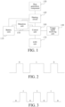
FIG. 1 is a schematic structural diagram of an aerosol vaporization device according to an embodiment of this application. -
FIG. 2 is a schematic diagram of a pulse signal according to an embodiment of this application. -
FIG. 3 is a schematic diagram of a pulse signal according to another embodiment of this application. -
FIG. 4 is a schematic structural diagram of a test device according to an embodiment of this application. -
FIG. 5 is a schematic structural diagram of a test device according to another embodiment of this application. -
FIG. 6 is a schematic structural diagram of a test device according to still another embodiment of this application. -
FIG. 7 is a schematic flowchart of an aerosol vaporization device control method according to an embodiment of this application. -
FIG. 8 is a schematic flowchart of an aerosol vaporization device control method according to another embodiment of this application. -
FIG. 9 is a schematic flowchart of an aerosol vaporization device test method according to an embodiment of this application. -
FIG. 10 is a schematic flowchart of an aerosol vaporization device test method according to another embodiment of this application. -
FIG. 11 is a structural block diagram of an aerosol vaporization device control apparatus according to an embodiment of this application. -
FIG. 12 is a structural block diagram of an aerosol vaporization device test apparatus according to an embodiment of this application. -
FIG. 13 is a diagram of an internal structure of a computer device according to an embodiment of this application. - To help understand this application, the following describes this application more fully with reference to the related accompanying drawings. Embodiments of this application are provided in the accompanying drawings. However, this application may be implemented in many different forms, and is not limited to the embodiments described in this specification. On the contrary, the embodiments are provided to make the disclosed content of this application more comprehensive and thorough.
- Unless otherwise defined, meanings of all technical and scientific terms used in this specification are the same as that usually understood by a person skilled in the technical field to which this application belongs. In this application, terms used in the specification of this application are merely intended to describe objectives of the specific embodiments, but are not intended to limit this application.
- It may be understood that terms "first", "second" and the like used in this application may be used to describe various elements in this specification, but the elements are not limited by the terms. The terms are merely used for distinguishing a first element from another element. For example, a first light-emitting diode (LED) and a second LED may be the same LED or may be different LEDs. Without departing from the scope of this application, the first LED may be referred to as the second LED, and similarly, the second LED may be referred to as the first LED.
- When used herein, the singular forms "a", "an" and "the" may also include the plural forms, unless otherwise clearly indicated in the context. It should be further understood that, the terms "include/contain" and "comprise" specify the presence of stated features, entireties, steps, operations, components, parts, or a combination thereof, but do not exclude the presence or addition of one or more other features, entireties, steps, operations, components, parts, or a combination thereof. In addition, the term "and/or" used in this specification includes any and all combinations of related listed items.
- In an embodiment, as shown in
FIG. 1 , anaerosol vaporization device 100 is provided, including abattery core 110, aheating circuit 120, and aheat generation component 130. Theaerosol vaporization device 100 further includes: - a trigger
signal receiving unit 140, configured to receive a trigger signal; - a
detection unit 150, configured to detect an operating parameter, where the operating parameter includes at least one measured parameter of the aerosol vaporization device; - a
control unit 160, configured to obtain the operating parameter fed back by thedetection unit 150 when receiving the trigger signal transmitted by the triggersignal receiving unit 140 and output a pulse signal after encoding the operating parameter; and - an
LED unit 170, configured to modulate a display level according to the pulse signal transmitted by thecontrol unit 160 and output a pulse display level. The display level is used for representing an operating state of the aerosol vaporization device. The pulse display level is provided to atest device 200 for detection and thetest device 200 obtains the operating parameter according to the pulse display level. Thebattery core 110 is configured to supply power to the vaporization device. The trigger signal is a signal trigger operation of theaerosol vaporization device 100, which may be a signal triggering startup of theaerosol vaporization device 100 or the beginning of vaporization. Specifically, the trigger signal may be inputted by a user or may be inputted by the test device. Thedetection unit 150 is configured to detect the operating parameter of theaerosol vaporization device 100, namely, measured parameters of elements and circuits in theaerosol vaporization device 100. Specifically, the operating parameter may include a measured parameter of thebattery core 110 and/or a measured parameter of theheat generation component 130, for example, a temperature of thebattery core 110, a voltage of thebattery core 110, and a resistance value, a current, or a voltage of theheat generation component 130. According to parameters that need to be measured, thedetection unit 150 may include one or more measurement modules. When thecontrol unit 160 receives the trigger signal, theheat generation component 130 starts to generate heat, and thecontrol unit 160 obtains the operating parameter detected by thedetection unit 150 and encodes the operating parameter to obtain a pulse signal and outputs the pulse signal to theLED unit 170. In some embodiments, in a process that thecontrol unit 160 encodes the operating parameter, 0 or 1 may be represented by using different time lengths of a level (as shown inFIG. 2 ), or 0 or 1 may be represented by using a conversion direction between high and low levels (as shown inFIG. 3 ). In some embodiments, the triggersignal receiving unit 140 may be a mems sensor. Thedetection unit 150 may be a temperature detection circuit, a voltage detection circuit, or a current detection circuit. Thecontrol unit 160 may be a microcontroller (MCU) or an application-specific integrated circuit (ASIC). - In some embodiments, the
LED unit 170 may be set to output the display level after startup or output the display level after heating is started as required, or may be set to output the display level after a preset heating time. The preset time is a duration from the startup/heating of theaerosol vaporization device 100 to a time at which aerosols start to be generated. According to a set operating state corresponding to outputting a display level, thecontrol unit 160 controls theLED unit 170 to output the display level when recognizes that the aerosol vaporization device is in the operating state. After thecontrol unit 160 outputs the pulse signal to theLED unit 170, theLED unit 170 outputs a pulse display level obtained by modulating the display level. - The test device has a capability of converting a recognized pulse optical signal into an electrical signal, so that the operating parameter of the
aerosol vaporization device 100 can be extracted by recognizing the pulse display level. - According to the
aerosol vaporization device 100, the operating parameter of the aerosol vaporization device detected by thedetection unit 150 is obtained by thecontrol unit 160 when a trigger signal is received, and a pulse signal is output to theLED unit 170 after the operating parameter is encoded, to modulate a display level of theLED unit 170 that represents the operating state of theaerosol vaporization device 100, so that theLED unit 170 is caused to output a pulse display level to a test device for detection. Therefore, the test device can obtain the operating parameter according to the pulse display level without detecting by means of an interface, so that the operating parameter of theaerosol vaporization device 100 can be detected conveniently and accurately. - In an embodiment, the aerosol vaporization device further includes:
- a
heating circuit 120, configured to drive aheat generation component 130 to generate heat; and - the
control unit 160 being further configured to output a heating signal to theheating circuit 120 when receiving the trigger signal, where the heating signal is used for controlling theheating circuit 120 to drive theheat generation component 130 to generate heat. - The
control unit 160 outputs a drive signal when receiving the trigger signal, and the drive signal is a pulse width modulation (PWM) signal used for driving theheating circuit 120 to control theheat generation component 130 to generate heat according to the PWM signal. - In an embodiment, the
control unit 160 is further configured to control the LED unit to output the display level when receiving the trigger signal. - In an embodiment, the pulse signal is a high-frequency pulse signal.
- A frequency of the high-frequency pulse signal is greater than a frequency that can be recognized by human eyes, so that the user cannot observe flashes of the pulse display level output by the
LED unit 170, visual perception during use of the user is not affected, and the user can still normally recognize the operating state of theaerosol vaporization device 100 according to the pulse display level output by theLED unit 170. - In an embodiment, the operating parameter further includes a resistance value of the
heat generation component 130 and/or an output power of theheating circuit 120. - The resistance value of the
heat generation component 130 and the output power of theheating circuit 120 are calculated by thecontrol unit 160 according to the operating parameter fed back by thedetection unit 150. - Because the resistance value of the
heat generation component 130 and the output power of theheating circuit 120 can be hardly directly obtained through detection of thedetection unit 150 of theaerosol vaporization device 100, thecontrol unit 160 may calculate the resistance value and the output power according to the operating parameter fed back by thedetection unit 150. Therefore, according to a test requirement, thecontrol unit 160 may calculate the resistance value of theheat generation component 130 and the output power of theheating circuit 120 according to the measured parameters of thebattery core 110 and theheat generation component 130. - In an embodiment, the trigger
signal receiving unit 140 includes a microphone. - If the
aerosol vaporization device 100 is an e-cigarette or a respirable medical vaporization device, the triggersignal receiving unit 140 includes a microphone. The microphone obtains a trigger signal through an airflow generated when the device is inhaled by the user during inhalation or breathing. - In an embodiment, as shown in
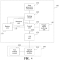
FIG. 4 , atest device 200 is provided, applicable to theaerosol vaporization device 100 according to any one of the foregoing embodiments. Thetest device 200 includes: - an
optical detection module 210, configured to detect the pulse display level output by theLED unit 170 of theaerosol vaporization device 100 and output a detection signal according to the pulse display level; and - a
test control module 220, configured to receive the detection signal transmitted by theoptical detection module 210 and obtain the operating parameter of theaerosol vaporization device 100 according to the detection signal. - The
optical detection module 210 is configured to detect the pulse display level, convert the pulse display level in an optical signal form into a detection signal in an electrical signal form, and output the detection signal to thetest control module 220. In an embodiment, theoptical detection module 210 may be an automated optical inspection (AOI) optical test instrument. Thetest control module 220 is an operating module having data processing and signal receiving and transmission capabilities, which can demodulate and decode the detection signal, to extract the operating parameter of theaerosol vaporization device 100. Thetest control module 220 demodulates the detection signal to obtain a pulse signal and then decodes the pulse signal to obtain the operating parameter of theaerosol vaporization device 100. In some embodiments, thetest control module 220 may be a MCU or an ASIC. - According to the
test device 200, the pulse display level output by theLED unit 170 of theaerosol vaporization device 100 is detected by theoptical detection module 210, and a detection signal is then output to thetest control module 220 according to the pulse display level. The operating parameter of theaerosol vaporization device 100 is obtained after the detection signal is processed by thetest control module 220. In this way, the operating parameter of theaerosol vaporization device 100 can be conveniently and accurately detected without detecting by means of an interface. - In an embodiment, as shown in
FIG. 5 , thetest device 200 further includes:
atrigger module 230, configured to input a trigger signal to the triggersignal receiving unit 140 of theaerosol vaporization device 100. - The
test control module 220 is further configured to control thetrigger module 230 to input the trigger signal to the triggersignal receiving unit 140. - To facilitate testing, the
trigger module 230 is set to automatically trigger theaerosol vaporization device 100 to start vaporization. When a test needs to be performed, thetest control module 220 controls thetrigger module 230 to input the trigger signal to the triggersignal receiving unit 140. - A type of the
trigger module 230 may be selected according to a type of the triggersignal receiving unit 140 in theaerosol vaporization device 100. For example, if a main part of the triggersignal receiving unit 140 is a microphone, thetrigger module 230 may be an apparatus that can change airflows, such as an automatic inhalation device. - In an embodiment, as shown in
FIG. 6 , thetest device 200 further includes:
adisplay module 240, configured to display the operating parameter transmitted by thetest control module 220. - The
display module 240 can intuitively display the operating parameter of theaerosol vaporization device 100 obtained through detection, to help a tester to obtain a test result. - In an embodiment, as shown in
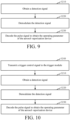
FIG. 7 , an aerosol vaporization device control method is provided, applicable to theaerosol vaporization device 100 according to any one of the foregoing embodiments. The method includes the following steps. - In
step S 110, an operating parameter fed back by thedetection unit 150 is obtained when receiving a trigger signal. Thedetection unit 150 is configured to detect the operating parameter of theaerosol vaporization device 100, and the operating parameter includes at least one measured parameter of theaerosol vaporization device 100. - In step S120, the operating parameter is encoded to obtain a pulse signal.
- In step S130, the pulse signal is transmitted to the
LED unit 170. The pulse signal is used for controlling theLED unit 170 to modulate a display level and output a pulse display level. The display level is used for representing an operating state of theaerosol vaporization device 100. The pulse display level is provided to thetest device 200 for detection and thetest device 200 obtains the operating parameter according to the pulse display level. - According to the aerosol vaporization device control method, when a trigger signal is received, an operating parameter detected by the
detection unit 150 is obtained, a pulse signal is obtained after the operating parameter is encoded, the pulse signal is transmitted to theLED unit 170 to control theLED unit 170 to modulate a display level output by the LED unit, so that theLED unit 170 outputs a pulse display level to thetest device 200 for detection, and thetest device 200 obtains the operating parameter according to the pulse display level. By utilizing an LED display function owned by the aerosol vaporization device including the LED unit in combination with the operating parameter fed back by the detection unit, tests on the operating parameter can be implemented without additionally setting a set of specific test software for the aerosol vaporization device. That is, an operating parameter transmission function may be superimposed on the LED display function of the aerosol vaporization device. - For example, for an aerosol vaporization device including an inhalation state LED display function, when the user performs inhalation, a first LED of the aerosol vaporization device may light up, and after the inhalation stops, the first LED lights off. Therefore, the pulse signal corresponding to the operating parameter may be superimposed in the stage that the first LED lights up. In an embodiment, the first LED may light up gradually when the user performs inhalation and maintain highlighted for a period of time, and light off gradually after the inhalation is stopped. To help the test device to obtain the operating parameter according to the pulse display level, the pulse signal may be superimposed in the stage that the first LED is highlighted.
- In another embodiment, the aerosol vaporization device further includes a charging state LED display function. A second LED may light up when the aerosol vaporization device is charged. For example, the second LED flashes in a charging state, the second LED is always on after the aerosol vaporization device is fully charged, and the second LED lights off after charging is stopped. Therefore, the pulse signal corresponding to the operating parameter may be superimposed on the stage that the second LED lights up.
- In an embodiment, the operating parameter further includes a resistance value of the
heat generation component 130 and/or an output power of theheating circuit 120. As shown inFIG. 8 , the aerosol vaporization device control method further includes the following step. - In step S140, the resistance value of the
heat generation component 130 and the output power of theheating circuit 120 are calculated according to the operating parameter fed back by thedetection unit 150, and the operating parameter is updated. - For a specific limitation on the aerosol vaporization device control method, reference may be made to the limitation on the
aerosol vaporization device 100 above. Details are not described herein again. - In an embodiment, as shown in
FIG. 9 , an aerosol vaporization device test method is further provided, applicable to thetest device 200 according to any one of the foregoing embodiments. The test method includes the following steps. - In step S210, a detection signal is obtained. The detection signal is an electrical signal output by the
optical detection module 210 according to the pulse display level output by theLED unit 170 of theaerosol vaporization device 100. - In step S220, the detection signal is demodulated to obtain a pulse signal corresponding to the pulse display level.
- In step S230, the pulse signal is decoded to obtain the operating parameter of the
aerosol vaporization device 100. - According to the aerosol vaporization device test method, a detection signal output according to the pulse display level output by the
LED unit 170 of theaerosol vaporization device 100 is obtained through theoptical detection module 210. The detection signal is demodulated to obtain a pulse signal corresponding to the pulse display level, and the pulse signal is then decoded to obtain the operating parameter of theaerosol vaporization device 100. - In an embodiment, as shown in
FIG. 10 , before the obtaining a detection signal, the test method further includes the following step. - In step S240, a trigger control signal is transmitted to the trigger module. The trigger control signal is used for controlling the trigger module to input a trigger signal to the trigger
signal receiving unit 140 of theaerosol vaporization device 100. - For a specific limitation on the aerosol vaporization device test method, reference may be made to the limitation on the
test device 200 above. Details are not described herein again. It should be understood that although the steps in the flowcharts ofFIG. 7 to FIG. 10 are sequentially displayed according to indication of arrows, the steps are not necessarily sequentially performed in the sequence indicated by the arrows. Unless clearly specified in this specification, there is no strict sequence limitation on the execution of the steps, and the steps may be performed in another sequence. In addition, at least some steps inFIG. 7 to FIG. 10 may include a plurality of substeps or a plurality of stages. The substeps or the stages are not necessarily performed at the same moment, and instead may be performed at different moments. The substeps or the stages are not necessarily performed sequentially, and instead may be performed in turn or alternately with another step or at least some of substeps or stages of the another step. - In an embodiment, as shown in
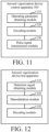
FIG. 11 , an aerosol vaporization device control apparatus 300 is provided, applicable to theaerosol vaporization device 100 according to any one of the foregoing embodiments. The control apparatus 300 includes: - an operating
parameter obtaining module 310, configured to obtain an operating parameter fed back by thedetection unit 150 when receiving a trigger signal, where thedetection unit 150 is configured to detect the operating parameter of theaerosol vaporization device 100; and the operating parameter includes at least one measured parameter of theaerosol vaporization device 100; - an
encoding module 320, configured to encode the operating parameter to obtain a pulse signal; and - a pulse
signal transmission module 330, configured to transmit the pulse signal to theLED unit 170, the pulse signal being used for controlling theLED unit 170 to modulate a display level and output a pulse display level, the display level being used for representing an operating state of the aerosol vaporization device, the pulse display level being provided to thetest device 200 for detection and thetest device 200 obtaining the operating parameter according to the pulse display level. - In an embodiment, the operating parameter further includes a resistance value of the
heat generation component 130 and/or an output power of theheating circuit 120. The aerosol vaporization device control apparatus 300 further includes:
a calculation module, configured to calculate the resistance value of theheat generation component 130 and the output power of theheating circuit 120 according to the operating parameter fed back by the detection unit, and update the operating parameter. - For a specific limitation on the aerosol vaporization device control apparatus, reference may be made to the limitation on the aerosol vaporization device control method above. Details are not described herein again. The modules in the foregoing aerosol vaporization device control apparatus may be implemented entirely or partially by software, hardware, or a combination thereof. The foregoing modules may be built in or independent of a processor of a computer device in a hardware form, or may be stored in a memory of the computer device in a software form, so that the processor invokes and performs an operation corresponding to each of the foregoing modules. It should be noted that, in the embodiments of this application, the module division is an example, and is merely logical function division, and there may be other division manners during actual implementation.
- In an embodiment, as shown in
FIG. 12 , an aerosol vaporization device test apparatus is further provided, applicable to thetest device 200 according to any one of the foregoing embodiments. The test apparatus includes: - a detection
signal obtaining module 410, configured to obtain a detection signal, where the detection signal is an electrical signal output by theoptical detection module 210 according to the pulse display level output by theLED unit 170 of theaerosol vaporization device 100; - a
demodulation module 420, configured to demodulate the detection signal to obtain a pulse signal corresponding to the pulse display level; and - a
decoding module 430, configured to decode the pulse signal to obtain the operating parameter of theaerosol vaporization device 100. - In an embodiment, the
aerosol vaporization device 100 test apparatus further includes:
a trigger control signal transmission module, configured to transmit a trigger control signal to the trigger module, the trigger control signal being used for controlling the trigger module to input a trigger signal to the triggersignal receiving unit 140 of theaerosol vaporization device 100. - For a specific limitation on the
aerosol vaporization device 100 test apparatus, reference may be made to the limitation on the aerosol vaporization device test method above. Details are not described herein again. The modules in the foregoingaerosol vaporization device 100 test apparatus may be implemented entirely or partially by software, hardware, or a combination thereof. The foregoing modules may be built in or independent of a processor of a computer device in a hardware form, or may be stored in a memory of the computer device in a software form, so that the processor invokes and performs an operation corresponding to each of the foregoing modules. It should be noted that, in this embodiment of this application, the module division is an example, and is merely logical function division, and there may be other division manners during actual implementation. - In an embodiment, a computer device is provided, including a memory and a processor, the memory storing a computer program, the processor, when executing the computer program, implementing the following steps.
- In step S110, an operating parameter fed back by the
detection unit 150 is obtained when receiving a trigger signal. Thedetection unit 150 is configured to detect the operating parameter of theaerosol vaporization device 100, and the operating parameter includes at least one measured parameter of the aerosol vaporization device. - In step S120, the operating parameter is encoded to obtain a pulse signal.
- In step S130, the pulse signal is transmitted to the
LED unit 170. The pulse signal is used for controlling theLED unit 170 to modulate a display level and output a pulse display level. The pulse display level is provided to thetest device 200 for detection and thetest device 200 obtains the operating parameter according to the pulse display level. - In an embodiment, the processor, when executing the computer program, further implements the following steps.
- In step S140, the resistance value of the
heat generation component 130 and the output power of theheating circuit 120 are calculated according to the operating parameter fed back by the detection unit, and update the operating parameter. - In an embodiment, as shown in
FIG. 13 , a computer device is further provided, including a memory and a processor, the memory storing a computer program, the processor, when executing the computer program, implementing the following steps. - In step S210, a detection signal is obtained. The detection signal is an electrical signal output by the
optical detection module 210 according to the pulse display level output by theLED unit 170 of theaerosol vaporization device 100. - In step S220, the detection signal is demodulated to obtain a pulse signal corresponding to the pulse display level.
- In step S230, the pulse signal is decoded to obtain the operating parameter of the
aerosol vaporization device 100. - In this embodiment, the computer device may be an independent computer, or may include an actual operating device applying one or more methods or the apparatus in one or more embodiments of this specification, and a diagram of an internal structure thereof is shown in
FIG. 13 . The computer device includes a processor, a memory, a communication interface, a display screen, and an input apparatus that are connected through a system bus. The processor of the computer device is configured to provide computing and control capabilities. The memory of the computer device includes a non-volatile storage medium and an internal memory. The non-volatile storage medium stores an operating system and a computer program. The internal memory provides an environment for running of the operating system and the computer program in the non-volatile storage medium. The communication interface of the computer device is configured to communicate with an external terminal in a wired or wireless manner. The wireless communication may be implemented by WI-FI, an operator network, near field communication (NFC), or other technologies. The display screen of the computer device may be a liquid crystal display screen or an electronic ink display screen. The input apparatus of the computer device may be a touch layer covering the display screen, or may be a key, a trackball, or a touch pad disposed on a housing of the computer device, and may further be an external keyboard, a touch pad, or a mouse. - A person skilled in the art may understand that, the structure shown in
FIG. 13 is merely a block diagram of a part of a structure related to a solution of this application and does not limit the computer device to which the solution of this application is applied. Specifically, the computer device may include more or fewer components than those in the figure, or some components may be combined, or a different component deployment may be used. - In an embodiment, the processor, when executing the computer program, further implements the following steps.
- In step S240, a trigger control signal is transmitted to the trigger module. The trigger control signal is used for controlling the trigger module to input a trigger signal to the trigger
signal receiving unit 140 of theaerosol vaporization device 100. - In an embodiment, a computer-readable storage medium is provided, storing a computer program, the computer program, when executed by a processor, causing the processor to implement the following steps.
- In step S110, an operating parameter fed back by the
detection unit 150 is obtained when receiving a trigger signal. Thedetection unit 150 is configured to detect the operating parameter of theaerosol vaporization device 100; and the operating parameter includes at least one measured parameter of the aerosol vaporization device. - In step S120, the operating parameter is encoded to obtain a pulse signal.
- In step S130, the pulse signal is transmitted to the
LED unit 170. The pulse signal is used for controlling theLED unit 170 to modulate a display level and output a pulse display level. The display level is used for representing an operating state of the aerosol vaporization device. The pulse display level is provided to thetest device 200 for detection and to obtain the operating parameter according to the pulse display level. - In an embodiment, the computer program, when executed by a processor, further causes the processor to implement the following steps.
- In step S140, the resistance value of the
heat generation component 130 and the output power of theheating circuit 120 are calculated according to the operating parameter fed back by thedetection unit 150, and update the operating parameter. - In an embodiment, a computer-readable storage medium is provided, storing a computer program, the computer program, when executed by a processor, causing the processor to implement the following steps:
In step S210, a detection signal is obtained. The detection signal is an electrical signal output by theoptical detection module 210 according to the pulse display level output by theLED unit 170 of theaerosol vaporization device 100. - In step S220, the detection signal is demodulated to obtain a pulse signal corresponding to the pulse display level.
- In step S230, the pulse signal is decoded to obtain the operating parameter of the
aerosol vaporization device 100. - In an embodiment, the computer program, when executed by a processor, further causes the processor to implement the following steps:
In step S240, a trigger control signal is transmitted to the trigger module. The trigger control signal is used for controlling the trigger module to input a trigger signal to the trigger signal receiving unit of the aerosol vaporization device. - A person of ordinary skill in the art may understand that all or some of procedures of the method in the foregoing embodiments may be implemented by a computer program instructing relevant hardware. The computer program may be stored in a non-volatile computer-readable storage medium. When the computer program is executed, the procedures of the foregoing method embodiments may be implemented. Any reference to a memory, a storage, a database, or another medium used in the embodiments provided in this application may include at least one of a non-volatile memory and a volatile memory. The non-volatile memory may include a read-only memory (ROM), a magnetic tape, a floppy disk, a flash memory, or an optical memory. The volatile memory may include a random access memory (RAM) or an external cache. For the purpose of description instead of limitation, the RAM is available in a plurality of forms, such as a static RAM (SRAM) or a dynamic RAM (DRAM).
- In the description of this specification, description of reference terms such as "some embodiments", "other embodiments", or "ideal embodiments", means including specific features, structures, materials, or features described in the embodiment or example in at least one embodiment or example of this application. In this specification, exemplary descriptions of the foregoing terms do not necessarily refer to the same embodiment or example.
- The technical features in the foregoing embodiments may be randomly combined. For concise description, not all possible combinations of the technical features in the embodiments are described. However, provided that combinations of the technical features do not conflict with each other, the combinations of the technical features are considered as falling within the scope described in this specification.
- The foregoing embodiments only describe several implementations of this application, which are described specifically and in detail, but cannot be construed as a limitation to the patent scope of the present disclosure. It should be noted that, a person of ordinary skill in the art may further make several variations and improvements without departing from the concept of this application, and such variations and improvements all fall within the protection scope of this application. Therefore, the protection scope of the patent of this application shall be subject to the appended claims.
Claims (17)
- An aerosol vaporization device, comprising:a trigger signal receiving unit, configured to receive a trigger signal;a detection unit, configured to detect an operating parameter, wherein the operating parameter comprises at least one measured parameter of the aerosol vaporization device;a control unit, configured to obtain the operating parameter fed back by the detection unit when receiving the trigger signal transmitted by the trigger signal receiving unit and output a pulse signal after encoding the operating parameter; anda light-emitting diode (LED) unit, configured to modulate a display level according to the pulse signal transmitted by the control unit and output a pulse display level, wherein the display level is used for representing an operating state of the aerosol vaporization device, the pulse display level is provided to a test device for detection and the test device obtains the operating parameter according to the pulse display level.
- The aerosol vaporization device according to claim 1, further comprising:a heating circuit, configured to drive a heat generation component to generate heat,wherein the control unit is further configured to output a heating signal to the heating circuit when receiving the trigger signal, the heating signal being used for controlling the heating circuit to drive the heat generation component to generate heat.
- The aerosol vaporization device according to claim 1, wherein the control unit is further configured to control the LED unit to output the display level when receiving the trigger signal.
- The aerosol vaporization device according to any one of claims 1 to 3, wherein the pulse signal is a high-frequency pulse signal.
- The aerosol vaporization device according to claim 4, wherein the operating parameter further comprises a resistance value of the heat generation component and/or an output power of the heating circuit, and
wherein the resistance value of the heat generation component and the output power of the heating circuit are calculated by the control unit according to the operating parameter fed back by the detection unit. - The aerosol vaporization device according to claim 4, wherein the trigger signal receiving unit comprises a microphone.
- A test device, configured to test the aerosol vaporization device according to any one of claims 1 to 6, the test device comprising:an optical detection module, configured to detect the pulse display level output by the LED unit of the aerosol vaporization device and output a detection signal according to the pulse display level; anda test control module, configured to receive the detection signal transmitted by the optical detection module and obtain the operating parameter of the aerosol vaporization device according to the detection signal.
- The test device according to claim 7, further comprising:a trigger module, configured to input a trigger signal to the trigger signal receiving unit of the aerosol vaporization device,wherein the test control module is further configured to control the trigger module to input the trigger signal to the trigger signal receiving unit.
- The test device according to claim 7, further comprising:
a display module, configured to display the operating parameter transmitted by the test control module. - An aerosol vaporization device control method, applicable to the aerosol vaporization device according to any one of claims 1 to 6, the method comprising:obtaining an operating parameter fed back by the detection unit when receiving a trigger signal, wherein the detection unit is configured to detect the operating parameter of the aerosol vaporization device, and the operating parameter comprises at least one measured parameter of the aerosol vaporization device;encoding the operating parameter to obtain a pulse signal; andtransmitting the pulse signal to the LED unit, wherein the pulse signal is used for controlling the LED unit to modulate a display level and output a pulse display level, the display level is used for representing an operating state of the aerosol vaporization device, and the pulse display level is provided to a test device for detection and the test device obtains the operating parameter according to the pulse display level.
- The aerosol vaporization device control method according to claim 10, wherein the operating parameter further comprises a resistance value of the heat generation component and/or an output power of the heating circuit, and
wherein the method further comprises:
calculating the resistance value of the heat generation component and the output power of the heating circuit according to the operating parameter fed back by the detection unit. - An aerosol vaporization device test method, applicable to the test device according to any one of claims 7 to 9, the method comprising:obtaining a detection signal, wherein the detection signal is an electrical signal output by the optical detection module according to the pulse display level output by the LED unit of the aerosol vaporization device;demodulating the detection signal to obtain a pulse signal corresponding to the pulse display level; anddecoding the pulse signal to obtain the operating parameter of the aerosol vaporization device.
- The aerosol vaporization device test method according to claim 12, wherein before the obtaining a detection signal, the method further comprises:
transmitting a trigger control signal to the trigger module, wherein the trigger control signal is used for controlling the trigger module to input a trigger signal to the trigger signal receiving unit of the aerosol vaporization device. - An aerosol vaporization device control apparatus, applicable to the aerosol vaporization device according to any one of claims 1 to 6, the apparatus comprising:an operating parameter obtaining module, configured to obtain an operating parameter fed back by the detection unit when receiving a trigger signal, wherein the detection unit is configured to detect the operating parameter of the aerosol vaporization device, and the operating parameter comprises at least one measured parameter of the aerosol vaporization device;an encoding module, configured to encode the operating parameter to obtain a pulse signal; anda pulse signal transmission module, configured to transmit the pulse signal to the LED unit, wherein the pulse signal is used for controlling the LED unit to modulate a display level and output a pulse display level, the display level is used for representing an operating state of the aerosol vaporization device, the pulse display level is provided to a test device for detection and the test device obtains the operating parameter according to the pulse display level.
- An aerosol vaporization device test apparatus, applicable to the test device according to any one of claims 7 to 9, the apparatus comprising:a detection signal obtaining module, configured to obtain a detection signal, wherein the detection signal is an electrical signal output by the optical detection module according to the pulse display level output by the LED unit of the aerosol vaporization device;a demodulation module, configured to demodulate the detection signal to obtain a pulse signal corresponding to the pulse display level; anda decoding module, configured to decode the pulse signal to obtain the operating parameter of the aerosol vaporization device.
- A computer device, comprising a memory and a processor, the memory storing a computer program, and the processor, when executing the computer program, implementing the steps of the method according to any one of claims 10 to 13.
- A computer-readable storage medium, storing a computer program, the computer program, when executed by a processor, causing the processor to implement the steps of the method according to any one of claims 10 to 13.
Applications Claiming Priority (2)
| Application Number | Priority Date | Filing Date | Title |
|---|---|---|---|
| CN202010559531.XA CN111913058A (en) | 2020-06-18 | 2020-06-18 | Aerosol atomization equipment, test equipment, control method and control device of aerosol atomization equipment and test equipment |
| PCT/CN2021/084327 WO2021253920A1 (en) | 2020-06-18 | 2021-03-31 | Aerosol atomization device, test device, control method therefor, and control apparatus thereof |
Publications (2)
| Publication Number | Publication Date |
|---|---|
| EP4169398A1 true EP4169398A1 (en) | 2023-04-26 |
| EP4169398A4 EP4169398A4 (en) | 2024-10-23 |
Family
ID=73237824
Family Applications (1)
| Application Number | Title | Priority Date | Filing Date |
|---|---|---|---|
| EP21825056.1A Pending EP4169398A4 (en) | 2020-06-18 | 2021-03-31 | AEROSOL ATOMIZATION DEVICE, TEST DEVICE, CONTROL METHOD THEREFOR AND CONTROL DEVICE THEREFOR |
Country Status (4)
| Country | Link |
|---|---|
| US (1) | US12075845B2 (en) |
| EP (1) | EP4169398A4 (en) |
| CN (1) | CN111913058A (en) |
| WO (1) | WO2021253920A1 (en) |
Families Citing this family (5)
| Publication number | Priority date | Publication date | Assignee | Title |
|---|---|---|---|---|
| CN111913058A (en) | 2020-06-18 | 2020-11-10 | 深圳麦克韦尔科技有限公司 | Aerosol atomization equipment, test equipment, control method and control device of aerosol atomization equipment and test equipment |
| CN113050513A (en) * | 2021-03-29 | 2021-06-29 | 深圳市吉迩科技有限公司 | Aerosol generating device and control system and control method thereof |
| CN114403513A (en) * | 2022-01-27 | 2022-04-29 | 深圳市吉迩技术有限公司 | Dual-waveform-based atomization output method and related equipment thereof |
| WO2024103361A1 (en) * | 2022-11-17 | 2024-05-23 | 思摩尔国际控股有限公司 | Aerosol forming apparatus and control method therefor |
| CN117958498B (en) * | 2024-04-01 | 2024-06-14 | 深圳市酷斯达科技有限公司 | Control method and system for self-protection of output of electronic atomizer |
Family Cites Families (18)
| Publication number | Priority date | Publication date | Assignee | Title |
|---|---|---|---|---|
| DE3267979D1 (en) * | 1981-04-27 | 1986-01-30 | Sumitomo Electric Industries | A method of and a system for pulse communication |
| US8680892B2 (en) * | 2011-06-29 | 2014-03-25 | Stmicroelectronics Asia Pacific Pte Ltd. | Reset pulse encoding and decoding scheme with no internal clock |
| CN203597405U (en) * | 2013-11-28 | 2014-05-21 | 胡朝群 | Intelligent electronic cigarette with wireless Bluetooth low-power-consumption connecting communication function |
| CN104664605A (en) * | 2013-11-28 | 2015-06-03 | 胡朝群 | Intelligent electronic cigarette with wireless Bluetooth low-power-consumption communication function |
| US10004269B2 (en) * | 2014-06-30 | 2018-06-26 | Huizhou Kimree Technology Co., Ltd. Shenzhen Branch | Control circuit, electronic cigarette and method for controlling electronic cigarette |
| US9609895B2 (en) | 2014-08-21 | 2017-04-04 | Rai Strategic Holdings, Inc. | System and related methods, apparatuses, and computer program products for testing components of an aerosol delivery device |
| GB201517088D0 (en) * | 2015-09-28 | 2015-11-11 | Nicoventures Holdings Ltd | Electronic aerosol provision systems and methods |
| US10231486B2 (en) * | 2016-03-10 | 2019-03-19 | Pax Labs, Inc. | Vaporization device having integrated games |
| FR3050618B1 (en) * | 2016-05-02 | 2023-12-15 | Sarl Gaiatrend | METHOD FOR CONTROLLING A VAPING DEVICE AND VAPING DEVICE FOR IMPLEMENTING THE METHOD |
| CN107231192A (en) * | 2017-02-28 | 2017-10-03 | 华南师范大学 | The data transmission method and LED visible light communication system of double level pulse widths codings |
| US12326794B2 (en) * | 2017-09-20 | 2025-06-10 | Rai Strategic Holdings, Inc. | Product use and behavior monitoring instrument |
| GB201721821D0 (en) * | 2017-12-22 | 2018-02-07 | Nicoventures Holdings Ltd | Electronic aerosol provision system |
| US10769038B2 (en) * | 2018-08-23 | 2020-09-08 | Arm Limited | Counter circuitry and methods including a master counter providing initialization data and fault detection data and wherein a threshold count difference of a fault detection count is dependent upon the fault detection data |
| JP6636117B1 (en) * | 2018-10-30 | 2020-01-29 | 日本たばこ産業株式会社 | Power supply unit of aerosol generation device, method of controlling power supply unit of aerosol generation device, and program for power supply unit of aerosol generation device |
| CN110037356B (en) * | 2019-05-24 | 2024-01-23 | 深圳达钿科技有限公司 | Control system and encryption method of split electronic cigarette |
| DE102019208612B4 (en) * | 2019-06-13 | 2024-09-05 | Siemens Healthineers Ag | Method for operating a magnetic resonance device with a patient bed and magnetic resonance device |
| CN110801055B (en) * | 2019-10-29 | 2023-03-31 | 歌尔微电子股份有限公司 | Electron cigarette circuit and electron cigarette |
| CN111913058A (en) * | 2020-06-18 | 2020-11-10 | 深圳麦克韦尔科技有限公司 | Aerosol atomization equipment, test equipment, control method and control device of aerosol atomization equipment and test equipment |
-
2020
- 2020-06-18 CN CN202010559531.XA patent/CN111913058A/en active Pending
-
2021
- 2021-03-31 WO PCT/CN2021/084327 patent/WO2021253920A1/en not_active Ceased
- 2021-03-31 EP EP21825056.1A patent/EP4169398A4/en active Pending
-
2022
- 2022-12-12 US US18/079,280 patent/US12075845B2/en active Active
Also Published As
| Publication number | Publication date |
|---|---|
| US20230106748A1 (en) | 2023-04-06 |
| US12075845B2 (en) | 2024-09-03 |
| EP4169398A4 (en) | 2024-10-23 |
| WO2021253920A1 (en) | 2021-12-23 |
| CN111913058A (en) | 2020-11-10 |
Similar Documents
| Publication | Publication Date | Title |
|---|---|---|
| US12075845B2 (en) | Aerosol atomization device, test device, control method therefor, and control apparatus thereof | |
| CN109062745B (en) | A test terminal with a test server hardware temperature | |
| CN111240973B (en) | Equipment testing method and system based on simulation and readable storage medium | |
| CN103793306A (en) | Testing method and device for automatic startup and shutdown of electronic products | |
| CN115079675B (en) | ECU test device, test method and test system | |
| CN106897219B (en) | Method and device for testing stability of mobile terminal system | |
| CN108645532B (en) | A temperature test device and temperature test method with a test temperature alarm function | |
| CN112328467B (en) | Embedded system program testing method and device | |
| CN215867583U (en) | Controller fault diagnosis test system | |
| CN112198861A (en) | Application program testing method of vehicle-mounted terminal | |
| WO2022095611A1 (en) | Battery rod, electronic atomization apparatus, detection device, and working method therefor | |
| CN112986805B (en) | Intelligent VPX board card testing method and system | |
| CN110209335A (en) | Control method and device of intelligent terminal | |
| CN101455568A (en) | Fatigue detection device | |
| CN117236931B (en) | Equipment management method and computer equipment | |
| CN115083387A (en) | Test system, test method, electronic device, and computer storage medium | |
| CN117138261A (en) | Control method of beauty instrument, beauty instrument and computer-readable storage medium | |
| JP2020087397A (en) | Method, device and system for reading intelligence information | |
| CN106126110B (en) | Terminal service control method, control device and terminal | |
| CN110308321A (en) | Dynamic current detection method and device | |
| CN114205277A (en) | Equipment fault monitoring method, device and equipment based on Modbus protocol | |
| CN108507617A (en) | Temperature-humidity detecting device and its detection method | |
| US10429451B2 (en) | Apparatus for testing luminaire based on USB and method using the same | |
| CN208999825U (en) | A kind of detection device and system of battery thermal management controller | |
| CN217521106U (en) | Multifunctional aging device acting on MEMS sensor |
Legal Events
| Date | Code | Title | Description |
|---|---|---|---|
| STAA | Information on the status of an ep patent application or granted ep patent |
Free format text: STATUS: THE INTERNATIONAL PUBLICATION HAS BEEN MADE |
|
| PUAI | Public reference made under article 153(3) epc to a published international application that has entered the european phase |
Free format text: ORIGINAL CODE: 0009012 |
|
| STAA | Information on the status of an ep patent application or granted ep patent |
Free format text: STATUS: REQUEST FOR EXAMINATION WAS MADE |
|
| 17P | Request for examination filed |
Effective date: 20230106 |
|
| AK | Designated contracting states |
Kind code of ref document: A1 Designated state(s): AL AT BE BG CH CY CZ DE DK EE ES FI FR GB GR HR HU IE IS IT LI LT LU LV MC MK MT NL NO PL PT RO RS SE SI SK SM TR |
|
| DAV | Request for validation of the european patent (deleted) | ||
| DAX | Request for extension of the european patent (deleted) | ||
| A4 | Supplementary search report drawn up and despatched |
Effective date: 20240920 |
|
| RIC1 | Information provided on ipc code assigned before grant |
Ipc: H05B 1/02 20060101ALI20240916BHEP Ipc: A24F 40/60 20200101ALI20240916BHEP Ipc: A24F 40/53 20200101ALI20240916BHEP Ipc: G01M 11/00 20060101ALI20240916BHEP Ipc: G01R 31/00 20060101ALI20240916BHEP Ipc: A24F 40/40 20200101AFI20240916BHEP |
|
| RAP3 | Party data changed (applicant data changed or rights of an application transferred) |
Owner name: SHENZHEN SMOORE TECHNOLOGY LIMITED |
|
| RAP3 | Party data changed (applicant data changed or rights of an application transferred) |
Owner name: SHENZHEN SMOORE TECHNOLOGY LIMITED |