EP4169384A1 - Attachment for dough mixers - Google Patents
Attachment for dough mixers Download PDFInfo
- Publication number
- EP4169384A1 EP4169384A1 EP22382969.8A EP22382969A EP4169384A1 EP 4169384 A1 EP4169384 A1 EP 4169384A1 EP 22382969 A EP22382969 A EP 22382969A EP 4169384 A1 EP4169384 A1 EP 4169384A1
- Authority
- EP
- European Patent Office
- Prior art keywords
- tool
- attachment
- dough mixers
- dough
- mixers
- Prior art date
- Legal status (The legal status is an assumption and is not a legal conclusion. Google has not performed a legal analysis and makes no representation as to the accuracy of the status listed.)
- Withdrawn
Links
Images


Classifications
-
- B—PERFORMING OPERATIONS; TRANSPORTING
- B01—PHYSICAL OR CHEMICAL PROCESSES OR APPARATUS IN GENERAL
- B01F—MIXING, e.g. DISSOLVING, EMULSIFYING OR DISPERSING
- B01F27/00—Mixers with rotary stirring devices in fixed receptacles; Kneaders
- B01F27/05—Stirrers
- B01F27/07—Stirrers characterised by their mounting on the shaft
- B01F27/071—Fixing of the stirrer to the shaft
-
- A—HUMAN NECESSITIES
- A21—BAKING; EDIBLE DOUGHS
- A21C—MACHINES OR EQUIPMENT FOR MAKING OR PROCESSING DOUGHS; HANDLING BAKED ARTICLES MADE FROM DOUGH
- A21C1/00—Mixing or kneading machines for the preparation of dough
- A21C1/14—Structural elements of mixing or kneading machines; Parts; Accessories
- A21C1/1405—Tools
-
- B—PERFORMING OPERATIONS; TRANSPORTING
- B01—PHYSICAL OR CHEMICAL PROCESSES OR APPARATUS IN GENERAL
- B01F—MIXING, e.g. DISSOLVING, EMULSIFYING OR DISPERSING
- B01F27/00—Mixers with rotary stirring devices in fixed receptacles; Kneaders
- B01F27/21—Mixers with rotary stirring devices in fixed receptacles; Kneaders characterised by their rotating shafts
- B01F27/2121—Mixers with rotary stirring devices in fixed receptacles; Kneaders characterised by their rotating shafts composed of interconnected parts
-
- F—MECHANICAL ENGINEERING; LIGHTING; HEATING; WEAPONS; BLASTING
- F16—ENGINEERING ELEMENTS AND UNITS; GENERAL MEASURES FOR PRODUCING AND MAINTAINING EFFECTIVE FUNCTIONING OF MACHINES OR INSTALLATIONS; THERMAL INSULATION IN GENERAL
- F16D—COUPLINGS FOR TRANSMITTING ROTATION; CLUTCHES; BRAKES
- F16D1/00—Couplings for rigidly connecting two coaxial shafts or other movable machine elements
- F16D1/06—Couplings for rigidly connecting two coaxial shafts or other movable machine elements for attachment of a member on a shaft or on a shaft-end
- F16D1/08—Couplings for rigidly connecting two coaxial shafts or other movable machine elements for attachment of a member on a shaft or on a shaft-end with clamping hub; with hub and longitudinal key
- F16D1/0852—Couplings for rigidly connecting two coaxial shafts or other movable machine elements for attachment of a member on a shaft or on a shaft-end with clamping hub; with hub and longitudinal key with radial clamping between the mating surfaces of the hub and shaft
- F16D1/0864—Couplings for rigidly connecting two coaxial shafts or other movable machine elements for attachment of a member on a shaft or on a shaft-end with clamping hub; with hub and longitudinal key with radial clamping between the mating surfaces of the hub and shaft due to tangential loading of the hub, e.g. a split hub
-
- F—MECHANICAL ENGINEERING; LIGHTING; HEATING; WEAPONS; BLASTING
- F16—ENGINEERING ELEMENTS AND UNITS; GENERAL MEASURES FOR PRODUCING AND MAINTAINING EFFECTIVE FUNCTIONING OF MACHINES OR INSTALLATIONS; THERMAL INSULATION IN GENERAL
- F16B—DEVICES FOR FASTENING OR SECURING CONSTRUCTIONAL ELEMENTS OR MACHINE PARTS TOGETHER, e.g. NAILS, BOLTS, CIRCLIPS, CLAMPS, CLIPS OR WEDGES; JOINTS OR JOINTING
- F16B7/00—Connections of rods or tubes, e.g. of non-circular section, mutually, including resilient connections
- F16B7/04—Clamping or clipping connections
- F16B7/0406—Clamping or clipping connections for rods or tubes being coaxial
- F16B7/0426—Clamping or clipping connections for rods or tubes being coaxial for rods or for tubes without using the innerside thereof
Definitions
- This invention is thus an attachment for dough mixers comprising a stop which is complementary to the shape of the end of the arm where the tool is installed and numerous fasteners which allow for the disassembly and extraction of tools in a quick way without having to disassemble large parts of the machine.
- At least one guide ensures that the tool does not move or shift out of its working position during operation.
Landscapes
- Engineering & Computer Science (AREA)
- General Engineering & Computer Science (AREA)
- Chemical & Material Sciences (AREA)
- Chemical Kinetics & Catalysis (AREA)
- Mechanical Engineering (AREA)
- Life Sciences & Earth Sciences (AREA)
- Food Science & Technology (AREA)
- Food-Manufacturing Devices (AREA)
- Manufacturing And Processing Devices For Dough (AREA)
Abstract
Description
- The purpose of this invention, as its name suggests, is to serve as an attachment for dough mixers which enables the kneading tool to be removed in a quick and simple manner, without having to disassemble a large portion of the machine. This is an innovation that, among the current technology, provides advantages unknown until now.
- This invention belongs to the food industry sector, more specifically to the bakery industry.
- This invention is an attachment for dough mixers, which allows the kneading tool to be changed quickly.
- As a reference to the current state of the art, it should be noted that, although a great variety and many models of dough mixers are known, the kneading tools or blades of these machines are inserted into the arm longitudinally and are held by a clamping device. This causes the changing of these tools to be a tedious and complicated process for users since practically the entire arm has to be disassembled, and the whole process keeps the machine inoperative for a considerable amount of time. To the applicant's knowledge, there does not exist any other invention with structural and constitutive technical characteristics equal or similar to those of the one claimed here.
- This invention is thus an attachment for dough mixers comprising a stop which is complementary to the shape of the end of the arm where the tool is installed and numerous fasteners which allow for the disassembly and extraction of tools in a quick way without having to disassemble large parts of the machine.
- In addition, at least one guide ensures that the tool does not move or shift out of its working position during operation.
- In order to complete the description being made and with the purpose of helping to better understand the characteristics of the invention, figures of an illustrative and nonlimiting nature, which are integral to this description, are included. The following has been depicted:
-
Figure 1 is a perspective drawing of a dough mixer. -
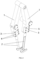
Figure 2 is a perspective drawing of both the arms (1) and tools (2) showing the attachment for dough mixers. -
Figure 3 is a perspective drawing of the arms (1) and the tools (2) where the attachment for dough mixers is shown, and one of the stops (3) is hidden. -
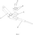
Figure 4 is a perspective drawing of an exploded view of the arms (1) and tools (2) showing the attachment for dough mixers. - In view of the figures, a preferred, but not limiting, embodiment of the proposed invention, which consists of an attachment for dough mixers, is described below. As can be seen in the figures, the attachment for dough mixers comprises one or more arms (1) which are part of the dough mixer at the end of which the tool (2) is coupled and fastened by a stop (3) which is configured to lock the tool (2) on the arm (1) by means of a numerous fasteners (4). At least one guide (5) is configured to prevent the tool (2) from slipping and being able to move from its working position during operation.
Claims (2)
- Attachment for dough mixers that comprises one or more arms (1) which are part of the mixer and at the end of which the tool (2) is coupled and fastened by means of a stop (3) which is configured to lock the tool (2) onto the arm (1) by means of numerous fasteners (4).
- Attachment for dough mixers according to claim 1, characterised by at least one guide (5) that is configured to prevent the tool (2) from slipping and moving from its working position during operation.
Applications Claiming Priority (1)
| Application Number | Priority Date | Filing Date | Title |
|---|---|---|---|
| ES202132052U ES1283329Y (en) | 2021-10-20 | 2021-10-20 | FIXATION FOR KNEADING MACHINES |
Publications (1)
| Publication Number | Publication Date |
|---|---|
| EP4169384A1 true EP4169384A1 (en) | 2023-04-26 |
Family
ID=78819699
Family Applications (1)
| Application Number | Title | Priority Date | Filing Date |
|---|---|---|---|
| EP22382969.8A Withdrawn EP4169384A1 (en) | 2021-10-20 | 2022-10-12 | Attachment for dough mixers |
Country Status (2)
| Country | Link |
|---|---|
| EP (1) | EP4169384A1 (en) |
| ES (1) | ES1283329Y (en) |
Citations (5)
| Publication number | Priority date | Publication date | Assignee | Title |
|---|---|---|---|---|
| DE464148C (en) * | 1928-08-10 | Albert Necke | Dough kneading machine with kneading arm moving vertically up and down in a driven kneading trough | |
| DE202010003490U1 (en) * | 2010-03-11 | 2010-06-10 | Teka Maschinenbau Gmbh | Tool for mixing device |
| EP2392396A2 (en) * | 2010-06-01 | 2011-12-07 | SANCASSIANO S.p.A. | System for fastening a kneading tool |
| US9381479B1 (en) * | 2013-05-17 | 2016-07-05 | The Boeing Company | Tool coupling and method for multi-component composition mixing |
| US20200124110A1 (en) * | 2018-10-18 | 2020-04-23 | Nebraska Irrigation, Inc. | Inline coupler |
-
2021
- 2021-10-20 ES ES202132052U patent/ES1283329Y/en active Active
-
2022
- 2022-10-12 EP EP22382969.8A patent/EP4169384A1/en not_active Withdrawn
Patent Citations (5)
| Publication number | Priority date | Publication date | Assignee | Title |
|---|---|---|---|---|
| DE464148C (en) * | 1928-08-10 | Albert Necke | Dough kneading machine with kneading arm moving vertically up and down in a driven kneading trough | |
| DE202010003490U1 (en) * | 2010-03-11 | 2010-06-10 | Teka Maschinenbau Gmbh | Tool for mixing device |
| EP2392396A2 (en) * | 2010-06-01 | 2011-12-07 | SANCASSIANO S.p.A. | System for fastening a kneading tool |
| US9381479B1 (en) * | 2013-05-17 | 2016-07-05 | The Boeing Company | Tool coupling and method for multi-component composition mixing |
| US20200124110A1 (en) * | 2018-10-18 | 2020-04-23 | Nebraska Irrigation, Inc. | Inline coupler |
Also Published As
| Publication number | Publication date |
|---|---|
| ES1283329Y (en) | 2022-02-25 |
| ES1283329U (en) | 2021-12-03 |
Similar Documents
| Publication | Publication Date | Title |
|---|---|---|
| EP1369210B1 (en) | Power tool accessory system | |
| EP4169384A1 (en) | Attachment for dough mixers | |
| GB1537089A (en) | Surgical staple extractor | |
| CN110405819B (en) | Glossy ganoderma is section device for production and processing | |
| EP3251797B1 (en) | Pliers | |
| CN203578778U (en) | Lathe device and clamping mechanism thereof | |
| US20020000044A1 (en) | Force-saving pruner with a guiding roller arrangement | |
| CN108724300B (en) | A portable processing device for large-diameter PP pipe | |
| CN109352699B (en) | An intermittent sheet cutting mechanism | |
| US20150086291A1 (en) | Adapter device for ceramic cutting machines | |
| US2595541A (en) | Tool for shaping the ends of conduits | |
| WO2005115702A2 (en) | Cutting device for tubular objects | |
| CN208445223U (en) | Conducting wire peeling component | |
| JP6366065B2 (en) | Sliding hammer | |
| JP5816103B2 (en) | Holder removal tool | |
| CN206403833U (en) | Foreskin rifle | |
| EP3277458B1 (en) | A cutting jig | |
| CN104409295A (en) | Clutch device for electric operating mechanism of circuit breaker | |
| US20210283796A1 (en) | Apparatus and Method for Causing Oscillating Motion of a Saw Blade, a Saw Blade, and a Method of Attaching a Saw Blade | |
| CN204929746U (en) | Pruning shears with variable operating modes | |
| CN105588727A (en) | Clamp type detecting and sampling device for animal skin sample | |
| US1597460A (en) | Wire-stripping machine | |
| CN207613817U (en) | The Quick assembling-disassembling structure of the execution head of surgery circular staplers | |
| JP3145878U (en) | Tube cutting shears | |
| CN112692793B (en) | Handheld device with replaceable working tool |
Legal Events
| Date | Code | Title | Description |
|---|---|---|---|
| PUAI | Public reference made under article 153(3) epc to a published international application that has entered the european phase |
Free format text: ORIGINAL CODE: 0009012 |
|
| STAA | Information on the status of an ep patent application or granted ep patent |
Free format text: STATUS: THE APPLICATION HAS BEEN PUBLISHED |
|
| AK | Designated contracting states |
Kind code of ref document: A1 Designated state(s): AL AT BE BG CH CY CZ DE DK EE ES FI FR GB GR HR HU IE IS IT LI LT LU LV MC ME MK MT NL NO PL PT RO RS SE SI SK SM TR |
|
| STAA | Information on the status of an ep patent application or granted ep patent |
Free format text: STATUS: REQUEST FOR EXAMINATION WAS MADE |
|
| 17P | Request for examination filed |
Effective date: 20231024 |
|
| RBV | Designated contracting states (corrected) |
Designated state(s): AL AT BE BG CH CY CZ DE DK EE ES FI FR GB GR HR HU IE IS IT LI LT LU LV MC ME MK MT NL NO PL PT RO RS SE SI SK SM TR |
|
| STAA | Information on the status of an ep patent application or granted ep patent |
Free format text: STATUS: EXAMINATION IS IN PROGRESS |
|
| 17Q | First examination report despatched |
Effective date: 20231201 |
|
| 17Q | First examination report despatched |
Effective date: 20240221 |
|
| STAA | Information on the status of an ep patent application or granted ep patent |
Free format text: STATUS: THE APPLICATION IS DEEMED TO BE WITHDRAWN |
|
| 18D | Application deemed to be withdrawn |
Effective date: 20250501 |