EP4169233B1 - Verfahren und entsprechendes telekommunikationsnetz zur gesicherten datenübertragung - Google Patents
Verfahren und entsprechendes telekommunikationsnetz zur gesicherten datenübertragung Download PDFInfo
- Publication number
- EP4169233B1 EP4169233B1 EP21743568.4A EP21743568A EP4169233B1 EP 4169233 B1 EP4169233 B1 EP 4169233B1 EP 21743568 A EP21743568 A EP 21743568A EP 4169233 B1 EP4169233 B1 EP 4169233B1
- Authority
- EP
- European Patent Office
- Prior art keywords
- node
- data packet
- data
- transmission
- block
- Prior art date
- Legal status (The legal status is an assumption and is not a legal conclusion. Google has not performed a legal analysis and makes no representation as to the accuracy of the status listed.)
- Active
Links
Images



Classifications
-
- H—ELECTRICITY
- H04—ELECTRIC COMMUNICATION TECHNIQUE
- H04L—TRANSMISSION OF DIGITAL INFORMATION, e.g. TELEGRAPHIC COMMUNICATION
- H04L9/00—Cryptographic mechanisms or cryptographic arrangements for secret or secure communications; Network security protocols
- H04L9/32—Cryptographic mechanisms or cryptographic arrangements for secret or secure communications; Network security protocols including means for verifying the identity or authority of a user of the system or for message authentication, e.g. authorization, entity authentication, data integrity or data verification, non-repudiation, key authentication or verification of credentials
- H04L9/3236—Cryptographic mechanisms or cryptographic arrangements for secret or secure communications; Network security protocols including means for verifying the identity or authority of a user of the system or for message authentication, e.g. authorization, entity authentication, data integrity or data verification, non-repudiation, key authentication or verification of credentials using cryptographic hash functions
-
- H—ELECTRICITY
- H04—ELECTRIC COMMUNICATION TECHNIQUE
- H04L—TRANSMISSION OF DIGITAL INFORMATION, e.g. TELEGRAPHIC COMMUNICATION
- H04L67/00—Network arrangements or protocols for supporting network services or applications
- H04L67/01—Protocols
- H04L67/10—Protocols in which an application is distributed across nodes in the network
- H04L67/104—Peer-to-peer [P2P] networks
-
- H—ELECTRICITY
- H04—ELECTRIC COMMUNICATION TECHNIQUE
- H04L—TRANSMISSION OF DIGITAL INFORMATION, e.g. TELEGRAPHIC COMMUNICATION
- H04L63/00—Network architectures or network communication protocols for network security
- H04L63/12—Applying verification of the received information
- H04L63/123—Applying verification of the received information received data contents, e.g. message integrity
-
- H—ELECTRICITY
- H04—ELECTRIC COMMUNICATION TECHNIQUE
- H04L—TRANSMISSION OF DIGITAL INFORMATION, e.g. TELEGRAPHIC COMMUNICATION
- H04L9/00—Cryptographic mechanisms or cryptographic arrangements for secret or secure communications; Network security protocols
- H04L9/32—Cryptographic mechanisms or cryptographic arrangements for secret or secure communications; Network security protocols including means for verifying the identity or authority of a user of the system or for message authentication, e.g. authorization, entity authentication, data integrity or data verification, non-repudiation, key authentication or verification of credentials
- H04L9/3236—Cryptographic mechanisms or cryptographic arrangements for secret or secure communications; Network security protocols including means for verifying the identity or authority of a user of the system or for message authentication, e.g. authorization, entity authentication, data integrity or data verification, non-repudiation, key authentication or verification of credentials using cryptographic hash functions
- H04L9/3239—Cryptographic mechanisms or cryptographic arrangements for secret or secure communications; Network security protocols including means for verifying the identity or authority of a user of the system or for message authentication, e.g. authorization, entity authentication, data integrity or data verification, non-repudiation, key authentication or verification of credentials using cryptographic hash functions involving non-keyed hash functions, e.g. modification detection codes [MDCs], MD5, SHA or RIPEMD
-
- H—ELECTRICITY
- H04—ELECTRIC COMMUNICATION TECHNIQUE
- H04L—TRANSMISSION OF DIGITAL INFORMATION, e.g. TELEGRAPHIC COMMUNICATION
- H04L9/00—Cryptographic mechanisms or cryptographic arrangements for secret or secure communications; Network security protocols
- H04L9/32—Cryptographic mechanisms or cryptographic arrangements for secret or secure communications; Network security protocols including means for verifying the identity or authority of a user of the system or for message authentication, e.g. authorization, entity authentication, data integrity or data verification, non-repudiation, key authentication or verification of credentials
- H04L9/3297—Cryptographic mechanisms or cryptographic arrangements for secret or secure communications; Network security protocols including means for verifying the identity or authority of a user of the system or for message authentication, e.g. authorization, entity authentication, data integrity or data verification, non-repudiation, key authentication or verification of credentials involving time stamps, e.g. generation of time stamps
-
- H—ELECTRICITY
- H04—ELECTRIC COMMUNICATION TECHNIQUE
- H04L—TRANSMISSION OF DIGITAL INFORMATION, e.g. TELEGRAPHIC COMMUNICATION
- H04L9/00—Cryptographic mechanisms or cryptographic arrangements for secret or secure communications; Network security protocols
- H04L9/50—Cryptographic mechanisms or cryptographic arrangements for secret or secure communications; Network security protocols using hash chains, e.g. blockchains or hash trees
Definitions
- the present invention to the field of telecommunications.
- the embodiments of the present invention present a method and a relevant telecommunications network configured for secure data transmissions.
- TOR network as well as virtual private network (VPN) systems allow data packets to be exchanged while maintaining the privacy of the entities accessing these networks and of the data exchanged.
- VPN virtual private network
- US 2015/0058933 proposes a technique for establishing a secure communication channel between a first computer and a second computer via a computer network.
- the technique comprises initially enabling a secure communication mode at the first computer without the user having to enter any encryption information to establish the secure communication channel.
- the secure communication channel between the first computer and the second computer is established via the computer network.
- the secure communication channel is a channel of a virtual private network established through the computer network in which one or more data values varying according to a semi-random sequence are inserted in each of the data packets.
- US 2018/0048738 proposes that devices in a wireless telecommunications network implement a blockchain distributed among the devices.
- a base station of the network receives, from a mobile device, a radio communication containing information associated with a blockchain transaction.
- the base station converts this information on the transition of a blockchain into a format based on an internet protocol.
- the base station updates the blockchain by propagating the Internet protocol-formatted information to the other base stations of the wireless telecommunications network via an Internet protocol-based network internal to the wireless telecommunications network.
- US 2017/0324738 proposes an Internet security system configured to provide security resources based on an 'Internet Blockchain'.
- the Internet Blockchain can be used to allow internet 'actors' such as internet ledgers, DNS entities, autonomous systems (ASes) and the like, to verify the ownership of internet resources such as IP addresses, AS numbers, IP prefixes, DNS domain names and the like by a specific internet actor.
- the Internet Blockchain makes it possible to verify transitions relating to Internet resources such as the allocation of IP addresses, AS numbers, IP prefixes, DNS domain names and the like requested by Internet actors.
- This system generally operates at the upper levels of the ISO/OSI model - generally from the transport level or higher - and thus relies on the TCP/IP structure for transferring data packets to the lower levels.
- WO 2019/229612 of the same Applicant proposes methods and systems for transferring data in an encrypted and certified manner by means of a protocol comprising a distributed digital ledger that generates sender and recipient addresses to establish a communication in which both the content and the channel are encrypted.
- US 2019/334697 describes a method for monitoring the communication and IT security in a distributed communication network.
- the distributed communication network comprises communication nodes. Each node is configured to communicate with another node and to store a local copy of a blockchain ledger. The method requires each communication node to be configured to generate a record to be added to the local copy of the blockchain ledger each time the communication node communicates with any other communication node in the distributed communication network.
- each communication node verifies and monitors the blockchain by means of the consensus between the communication nodes and by comparing the hashes of the previous blocks in the blockchain.
- An object of the present invention is to overcome the drawbacks of the prior art.
- a further scope of the present invention is to propose a method of communication between nodes of the telecommunication network which allows to associate to the data packets transmitted by the nodes of the network a substantially unalterable timestamp in a dynamic way, in particular in a decentralised way, i.e. without the need to implement a certifying node or other similar entity in the telecommunication network.
- a further purpose of the present invention is to propose a method of communication between nodes in a telecommunications network that enables the transfer of data packets securely over an encrypted communication channel with low computational cost and latency.
- the present invention is directed to a method of communication between nodes of a telecommunications network, wherein each node maintains a copy of a shared digital log.
- the method comprises that each sending node of a plurality of data packets, for each data packet to be transmitted, executes the steps of:
- the method further comprises:
- the generation of the hash value by means of the hashing algorithm with sequential operations guarantees that it is not possible to predict or anticipate the hashing value using hardware with higher performance than the nodes of the network.
- the method thus makes it possible to order a sequence comprising a plurality of data packets independently of the content of the data packet and/or the protocol used to transmit that data packet.
- the step of ordering the data packets comprises ordering the data packets according to count values comprised in a data block header that contains a record of the transmission of the corresponding data packet, said count value increasing as the position of the data block in the digital ledger increases.
- the record of the transmission of the data packet comprises a timestamp associated with the corresponding data packet
- the step of ordering the data packets comprises ordering those two or more data packets according to the time stamps comprises in the corresponding records of the transmission.
- the step of ordering the data packets comprises ordering said two or more data packets according to hash values associated with the corresponding transmission records calculated by the hashing algorithm.
- the hashing algorithm comprises performing a predetermined number of iterations of an encryption algorithm, each iteration of the encryption algorithm receiving as input the result of the previous iteration.
- the hashing algorithm may receive as input a value associated with the data packet whose transmission is to be recorded in the data block being processed.
- the encryption algorithm is a SHA-2 encryption algorithm or, even more preferably, it is a SHA-3 encryption algorithm.
- the step of recursively generating a shared digital ledger data block comprises each node:
- the verification procedure By implementing the verification procedure as indicated, it is possible to quickly check the correctness of the data blocks to be inserted in the shared digital ledger.
- the verification procedure does not require the use of multiple processors in parallel to be performed quickly, so it can be performed quickly even on portable devices with limited hardware capabilities.
- each data block can be quickly verified by the nodes of the network.
- the encryption algorithm and the verification algorithm allow data blocks to be processed with sufficient timing to handle a flow of data packets suitable for establishing an instant messaging service, voice or video communication.
- the hashing algorithm and the verification algorithm are algorithms of a verifiable delay function.
- the hashing algorithm provides an unalterable proof of history (PoH) indicating a temporal order of generation of the blocks of the digital ledger.
- PoH unalterable proof of history
- PoH shared digital ledger based on PoH.
- This makes it possible to obtain both a secure and unalterable timestamp of the instant of generation of the digital ledger blocks and, therefore, of the payload data contained in the blocks.
- the use of PoH makes it possible to generate and verify ledger blocks much faster than algorithms that implement a proof of work or even a proof of stake. This makes it possible to adequately handle high data flows, such as data exchanged between terminals in a telecommunications network.
- each sender node for each data packet to be transmitted, further performs the step of acquiring a timestamp certified by a timestamp authority at the generation of the data packet to be transmitted.
- the quest to record said data packet transmission comprises said certified timestamp.
- any data packet transmitted in the network and recorded in the digital ledger can be reliably synchronised.
- the certified timestamp as a time reference, it is possible to avoid inconsistencies due to the lack of synchronisation between the clocks of each node in the telecommunications network, thus reducing the possibility of alteration of data packets by third parties.
- the request for registration of the data packet transmission includes:
- the method comprises storing in a portion of the data block said at least one information on the transmitted data packet.
- the method comprises:
- the request for registration of the data packet transmission comprises:
- Including the hash value associated with the last data block in the shared digital ledger allows for an additional certification to that provided by the hash value in which the transmission of the data packet is recorded. Thanks to this double information, it is possible to guarantee an even more precise and reliable time order of the data packets. At the same time, the robustness against alteration attempts by third parties is also increased.
- the method further comprises that each node:
- each transmission information contained in the data blocks is encrypted by means of a first encryption code of the recipient and/or digitally signed by means of a second encryption code of the sender.
- the step of from its copy of the distributed ledger transmission information contained in the data blocks relating to transmissions of a data packet for which said node is not the sending node or the receiving provides that said node:
- a different aspect of the present invention concerns a telecommunications network comprising a plurality of nodes.
- Each node comprises at least one data processing module, a memory module and a transceiver module.
- each node is configured for:
- each node of the telecommunications network comprises a smartphone, a tablet, a computer, a radio base station, an evolution Node B, a WiFi modem or router or another similar device.
- reference 1 indicates a telecommunications network - abbreviated to 'network' in the following - according to an embodiment of the present invention.
- the network 1 comprises a plurality of network nodes, nine network nodes N1-N9 in the non-limiting example considered, capable of exchanging information through electromagnetic signals, preferably - albeit not limited - by means of electromagnetic waves.
- the generic node Nx of the network 1 (with x comprised between 1 and 9 in the example considered) comprises a processing module 10 configured for implementing one or more data processing algorithms, a memory module 20 configured for storing data, and a transceiver module 30 configured for establishing and managing one or more connections with at least one node of the network 1.
- the processing module 10 comprises one or more processors, microprocessors, microcontrollers, ASICs, FPGAs, DSPs or the like.
- the memory module 20 comprises one or more nonvolatile and volatile memory elements suitable for storing data, preferably in a binary format.
- the transceiver module 30 comprises at least one modem for communications via electromagnetic radiations (Wi-Fi, Bluetooth, GSM, UMTS, LTE/LTE-A, 5G, etc.) and optionally a modem for wired communications.
- the processing module 10 comprises one or more additional modules 40, for example, the node Nx may comprise an interface module configured for supplying data and/or receiving instructions from an external entity such as a user or other device, and additionally or alternatively a sensing module comprising one or more sensors, selected among motion sensors - such as one or more among accelerometers, gyroscopes, gravity sensors, etc. -, position sensors - such as one or more among magnetometers, a GNSS sensing system, etc. - and environmental sensors - such as one or more among barometers, photometers, thermometers, microphones, cameras, proximity sensors, etc., and biometric sensors - such as a fingerprint reader.
- motion sensors such as one or more among accelerometers, gyroscopes, gravity sensors, etc. -
- position sensors - such as one or more among magnetometers, a GNSS sensing system, etc.
- environmental sensors - such as one or more among barometers, photometers, thermometers, microphones,
- the generic node Nx of the network 1 comprises a power circuitry (not illustrated) configured for powering modules 10- 40 of the node Nx and, if applicable, ancillary circuitry required for the proper operation of the modules 10 - 40.
- the generic node Nx of the network 1 comprises, but is not limited to: a smartphone, a tablet, a personal computer, a radio base station, an eNodeB, a wireless modem and the like.
- the generic node Nx of the network 1 memorizes an identification code IDx that allows the node Nx to be uniquely identified in the network.
- the identification code IDx is a hash value representing a public address associated with a private encryption key corresponding to a second hash value - similar to the public address and to the private key of a cryptocurrency wallet.
- the identification code attributed to the node Nx by a registration entity IDx and the corresponding private encryption key are generated and assigned to the node Nx by a registration entity ER when a network insertion request 1 is executed by the node Nx.
- the registration entity ER is also configured for operating as a network node 1.
- the registration entity ER is implemented by a remote server accessible via a connection based on secure TCP/IP protocol.
- the generic node Nx stores a list Rx of one or more identification codes associated with respective nodes of the network 1 with which it exchanged data in the past and/or habitually exchanges data.
- the generic node Nx of the network 1 maintains - stores and updates - a copy of a shared digital ledger Lx, which will be referred to as 'ledger' in the following for brevity's sake.
- the generic node Nx runs a software application AS configured for managing the exchange of information across a peer-to-peer (P2P) network in order to enable the exchange of information between nodes of the network 1 by transmitting data packets and maintaining the ledger Lx according to the procedures described below.
- P2P peer-to-peer
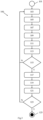
- the nodes N1-N9 of the network 1 are configured for exchanging data with each other, preferably grouped in data packets dp, by executing a transceiving procedure 100 in accordance with an embodiment of the present invention and illustrated schematically by the flowchart of Figure 3 .
- one piece of information to be communicated is represented by a plurality of binary data which are subdivided into sequential pieces of information, each of which is transmitted in a corresponding data packet. Information can then be reconstructed by extracting the portions of information from the received data packets and by ordering them in the correct order.
- the procedure 100 begins when an application running on a first node of the network 1 - node N1 in the example under consideration - requests a transfer of information to a second node of the network 1 - node N9 in the example at issue (start block 101).
- the procedure 100 comprises selecting a node N1-N9 of the network 1 to which to transfer the data packet dp (block 103) among the nodes comprised whose identification code ID1-ID9 is comprised in the list R1 of the sender node N1.
- the selection allows obtaining a sequence of nodes of the network that allows delivering a data packet to the recipient node N9 through a corresponding sequence of transmissions of the data packet dp from one node to another node that ensures low latency and low energy consumption.
- the procedure 100 allows using the minimum sequence of nodes of the network that allows delivering the data packet dp to the recipient node N9 through a minimum number of transmissions of the data packet dp from one node to another node.
- the node to which the above mentioned data packet dp is to be transferred is identified by means of a graph database DBG1-DGB9 referred to the corresponding node N1-N9, of which the graph databases DBG1 and DBG3 relating to the nodes N1 and N3 are schematically illustrated in Figures 4a and 4b .
- the node N1-N9 to which to transmit the packet dp is selected by implementing a node selection procedure 200 (illustrated in Figure 5 ).
- the procedure 200 once started (start block 201) comprises populating the graph database DBG1 referred to the sender node N1 - or, in subsequent iterations, a graph database DBG2-DBG8 of an intermediary receiver node N2-N8 - which must transmit the data packet dp.
- the generic graph database DBGx is populated in such a way that each node of the graph database DBGx comprises a node N1-N9 whose identification code ID1-ID9 code is stored in the list Rx of the generic node Nx considered and that each arc connects the generic node Nx to a respective node N1-N9 whose identification code ID1-ID9 is stored in the list Rx of the generic node Nx (block 203).
- the graph database DBG1 of the sender node N1 comprises the nodes N2, N3, N5, N7 and N8 whose identification codes ID2, ID3, ID5, ID7 and ID8 are contained stored in the list R1 of the sender node N1, while in Figure 4b the graph database DBG3 of the receiver node N3 comprises the nodes N1, N4, N6 and N9 whose identification codes ID1, ID4, ID6 and ID9 are stored in the list R3 of the receiver node N3.
- the procedure 200 comprises detecting an indication of the current position P1-P9 of the corresponding node N2-N9 of network 1 associated with a graph database DBG1 of the node N1 (block 205).
- the position indication P1-P9 is added to the corresponding node of the graph database DBG1.
- the position indication comprises one or more among: a geographic position measured by a global navigation satellite system (GNSS), information relating to a cellular network cell to which the node N1-N9 is connected (in the case of a mobile device), an IP address associated with the node N1-N9, an Access Point Name (APN) to which the network node is connected, geolocation data (geolocation or geotag) associated with the node N1-N9 by geomessaging, geomarketing services etc. used.
- GNSS global navigation satellite system
- APN Access Point Name
- geolocation data geolocation or geotag
- the instances of the software application AS running on the generic node Nx is configured for acquiring the position indication P1-P9 referred to the respective node Nx and making it available to another node N1-N9 of the network 1 that requests it.
- the software application AS running on the generic node Nx is configured for detecting and transmitting, preferably periodically, the current position indication P1-P9 to each node N1-N9 whose identification code ID1-ID9 is stored in the list Rx of the generic node Nx considered.
- the procedure 200 comprises detecting a current capability S1-S9 to establish a communication channel to receive and/or forward the data packet dp from each node N1-N9 of the network 1 associated with a corresponding node of the graph database DBG1 (block 207).
- this capacity indication S1-S9 is added to the corresponding node of the graph database DBG1.
- the procedure 200 comprises selecting a receiver node among the database nodes DBG1 to which to transfer the data packet dp (block 209).
- the node with the shortest distance from the central node - i.e. the sender node N1 - of the graph database DBG1 is selected as the receiver node.
- the node with the shortest distance corresponds to network node N3.
- the minimum distance node is identified by comparing the position indications P2-P9 associated with the nodes of the graph database DBG1 with the position indication P1 associated with the central node of the graph database DBG1, i.e. the sender node N1, and identifying the node at a shorter distance than the others.
- Distance herein means a measure (e.g. a linear measure) or a set of measures (e.g. a set of measures/vectors in a Cartesian or polar coordinate system) that allows a spatial separation between two network nodes to be determined. More generally, “distance” refers to a separation between two nodes that requires a non-zero time to transmit a data packet from one node to the other. In this case, the node with the shortest distance is the node with the shortest time delay to be reached by a data packet. However, the minimum distance ensures that the transmission of the data packet from one node to another occurs within a timeout interval, i.e., without requiring retransmissions of the data packet.
- a measure e.g. a linear measure
- measures e.g. a set of measures/vectors in a Cartesian or polar coordinate system
- the procedure 200 comprises checking that a communication channel can actually be established with the selected node (decision block 211).
- the procedure 200 comprises checking the capacity S3 to establish a communication channel of the node N3 at a shorter distance.
- the node with the shortest distance is discarded (block 213) and the procedure 200 comprises selecting a new minimum path by repeating the steps described above from block 209.
- the procedure 200 provides, first, for outputting the identification code associated with the node N3 of the network 1 (block 215) for the continuation of the procedure 100 and then to terminate (at the end block 217).
- the procedure 100 comprises generating the data packet dp (illustrated schematically in Figure 6 ) comprising at least a portion of the information to be transmitted to the recipient node N9 (block 105).
- the data packet dp comprises a header, or header HR, and a payload, or payload PL.
- the header HR comprises a sender field ID-M in which there is reported the identification code ID1 of the sender node N1 of the data packet dp, a recipient field ID-D in which it is reported the identification code ID9 of the recipient node N9 of the data packet dp, a receiver field ID-R in which it is reported the identification code of the node to which the packet is actually to be transmitted and, optionally, a timestamp TS indicating an instant of time of the generation of the data packet dp as measured by the node N1 in question - for example, through an internal clock of the relative processing module 10.
- the timestamp TS is a certified timestamp, to be acquired/provided by the Registration Entity ER or a Time Stamping Authority (or TSA) rather than a timestamp generated locally by the sender node N1.
- the certified timestamp is obtained at the request of the sender node N1 in conjunction with the generation of the data packet dp.
- the procedure 100 comprises inserting in the receiver field ID-R the identification code of the node N3 selected by means of the procedure 200 described above.
- the payload PL of the data packet dp comprises the information or, more typically, a portion of the information to be transmitted.
- at least the payload PL of the data packet dp is encrypted with the identification code of the recipient node N9 so that its content is decryptable to the recipient node N9 only.
- the data packet dp By generating the data packet dp, it is transmitted from the sender node N1 to the node, N3 in the example considered, whose identification code ID3 is comprised in the receiver node field ID-R (block 107).
- the data packet is encoded in an electromagnetic radiation radiated by the transceiver module 30 of the sender node N1.
- the procedure 100 comprises that a request to record the transmission of the data packet dp in a data block Bn of the ledger copies L1-L9 maintained by the nodes N1-N9 of the network 1 is carried out (block 109).
- the nodes N1-N9 of the network 1 share the data contained in the ledger copies L1-L9 by establishing a peer-to-peer (P2P) structure substantially in accordance with the Distributed Ledger Technology (DLT), as follows.
- P2P peer-to-peer
- DLT Distributed Ledger Technology
- the nodes N1-N9 of the network 1 Upon receipt of such a registration request, the nodes N1-N9 of the network 1 record the transmission of the data packet dp within the data block Bn being generated at the time of receipt of the registration request by the node N1 (block 111).
- the generic copy of the ledger Lx comprises a plurality of data blocks Bn, Bn-1, Bn-2, Bn-3, etc. from a source data block B0, which are concatenated together in chronological order to form an unalterable data structure, as illustrated schematically in Figure 7 .
- each block is marked by a header HB that contains a unique hash value Hn associated with the Bn data block, a hash value Hn-1 associated with the previous data block Bn-1 in the chain of blocks forming the distributed ledger Lx, and a count value Cn that increases as the position of the data block Bn in the block chain of the ledger Lx increases.
- the data block Bn comprises a body BD in which one or more transmission records rdp are stored.
- the registration of the transactions within the data blocks Bn of the ledger L1 - L9 takes place through a recording procedure 300 - of which Figure 8 is a flow chart.
- the procedure 300 comprises generating a new data block Bn of the ledger Lx by applying a proof-of-history protocol, which makes it possible to certify a temporal order of creation and addition of the data block Bn to the ledger Lx (block 301).
- each block is generated when a generic node Nx of the network 1 calculates the hash value Hn of the data block Bn by means of a hashing algorithm f H (e.g. based on the SHA-2 or SHA-3 family of encryption algorithms) from a hash value Hn-1 associated with the previous data block Bn-1 in the chain of blocks forming the distributed ledger Lx and, possibly, one or more additional values.
- f H e.g. based on the SHA-2 or SHA-3 family of encryption algorithms
- the hashing algorithm f H requires at least a minimum hashing time t H to be performed on a parallel random-access machine (PRAM) having a predetermined number of processors p.
- the hashing function f H implemented comprises the sequential execution - which cannot be parallelised - of a predetermined number of operations.
- the hashing algorithm f H comprises N iterations of an encryption algorithm SHA-2, more preferably SHA-3, each iteration of the algorithm receiving as input at least the hashing value calculated at the previous iteration. Consequently, the hashing time t H required for the execution of the hashing function f H from any node N1-N9 of the network 1 is the sum of the times needed to execute each of these operations.
- the hash Hn can be verified by means of a verification algorithm v H in a verification time t v which is much shorter than the hashing time t H .
- the verification algorithm v H can be executed using parallel processing on multiple processors.
- the hashing algorithm f H and the verification algorithm v H suitable for use in the embodiments can be defined as algorithms for the evaluation and verification, respectively, of a Verifiable Delay Function defined in accordance with Dan Boneh, Joseph Bonneau, Benedikt Bünz, Ben Fisch: "Verifiable Delay Functions” Advances in Cryptology - CRYPTO 2018, Volume 10991 .
- the procedure 300 comprises inserting in the body BD of the data block Bn, which is being generated, one or more transmission records for which a request is received during the hashing time t H of the data block Bn (block 303).
- the request for recording the transmission of the data packet dp comprises information on the data packet dp and, optionally, the hash value Hn-1 of the last data block Bn-1 comprised in the copies of the ledger L1-L9 at the time of transmission of the data packet dp.
- the information on the data packet dp comprises one of, preferably both, the identification codes ID1 and ID9 of the sender node N1 and the recipient node N9, and additionally or alternatively an identification code of the data packet dp and/or of a sequence of data packets to which the data packet dp belongs.
- the information contained in the registration request shall be encrypted by means of the identification code ID9 of the recipient node N9 and/or signed by means of the identification code ID1 of the sender node N1.
- each transmission record rdp stored in the body BD is associated in an unalterable way with the hash value Hn and the count value Cn of the data block Bn, thus providing a certain time indication of the transmission of the corresponding data packet dp.
- the request for recording the transmission of the data packet dp also comprises the certified timestamp, mentioned above.
- the data block Bn thus generated is added to the copies of the ledger L1-L9 after having been verified - by means of the verification algorithm v H - by the nodes N1-N9 of the network 1 (block 305).
- the procedure 300 then comprises repeating the steps described above from block 301 to generate a new data block Bn+1 whose hash value Hn+1 is calculated from the hash value Hn of the data block Bn.
- the transmitted data packet dp is received by the node indicated in the receiver field ID-R - the node N3 in the case under consideration - (block 113) and it is verified whether this node of the network 1 corresponds to the recipient node N9 (decision block 115).
- the procedure 100 comprises repeating the previous steps starting from the determination of a graph database DBG3 - illustrated in Figure 4b - of which the receiver node N3 is the central node so as to determine a new node N1-N9 to which to transmit the packet (block 103, procedure 200), to modify the receiver field ID-R of the data packet dp by inserting the identification code ID1-ID9 associated with the identified node N1-N9 (block 105) and then to transmit the data packet dp to the same (block 107) while requesting (block 109) the registration of the transmission in a new block of the ledger L1-L9 (which is done as described in relation to block 111 and procedure 300) and to verify again whether the data packet dp has been received by the recipient node N9 (blocks 113 and 115).
- the procedure 100 provides that a time information associated with the packet dp is identified through the copy of the ledger L9 stored by the recipient node N9 (block 117).
- a time information associated with the packet dp is identified through the copy of the ledger L9 stored by the recipient node N9 (block 117).
- the procedure 100 requires the recipient node N9 to generate and transmit a reply packet rp to acknowledge receipt of the data packet dp (block 119).
- the reply packet rp (illustrated schematically in Figure 9 ) comprises a header, or header HR, and a payload, or payload PL.
- the header HR comprises a sender field ID-M in which there is reported the identification code ID1 of the sender node N9 of the reply packet rp, a recipient field ID-D in which it is reported the identification code ID1 of the recipient node N1 of the reply packet rp, a receiver field ID-R in which it is reported the identification code of a receiver node to which the packet is actually to be transmitted and, optionally, a timestamp TS indicating an instant of time of the generation of the reply packet dp as measured by the node N9.
- the payload PL of the data packet dp comprises a reference to the received data packet dp.
- the procedure 100 comprises inserting in the receiver field ID-R the identification code of a node N1-N9 of the network 1 selected by means of procedure 200 described above - which may be different from the node N3 used for transmission of the data packet dp.
- the reply packet rp will be transmitted between one or more nodes until reaching the sender node N1 of the data packet dp in a manner analogous to that described above in relation to blocks 103 - 107 and not repeated here for brevity's sake.
- the reply packet rp is not required to be recorded on the transmission in the copies of the ledger L1-L9.
- the procedure 100 comprises checking whether there are one or more other data packets dp' to be transmitted (decision block 123). In the affirmative case (Y branch of block 123), the procedure 100 comprises repeating the steps described above from what is described in relation to block 103 to transfer a new data packet dp' . Otherwise, if there are no more data packets dp' to transmit (branch N of block 123), the procedure 100 ends (termination block 125.)
- each node N1-N9 deletes from the body of data blocks B0, ..., Bn+1 of its copy of the shared digital ledger L1-L9 the transmission records referring to transmissions in which it did not act as sender node or recipient node.
- each node is configured to delete transmission records that it is unable to decipher by means of its private key or that are not signed by means of its identification code.
- the registration entity ER comprises executing a procedure 400 of population of the list Rx of identification codes stored by the generic node Nx at the time of the registration of the latter in the network 1.
- the procedure 400 is initiated when the generic node Nx requests insertion into network 1 and, at the same time, generation of its identification code IDx and associated private encryption key (start block 401).
- the procedure comprises analysing a list of contacts stored in the node Nx (block 403) - for example, the telephone book and/or a list of known e-mail addresses in the case of a mobile device - and checking whether one of the contacts recorded in this list is associated with a node of the network 1 (block 405).
- the registration entity ER is configured to check whether one or more of the contacts comprised in the contact list of the node Nx is associated with a corresponding identification code ID1-ID9 of the network.
- the registration entity ER maintains and updates a list of nodes of the network 1; preferably, each entry in the list comprises an identification code ID1-ID9 and at least one other identifier element of the network node Nx - for example, an e-mail address, a telephone number/IMSI code, a telephone IMEI code or a modem MAC code, or other similar identifier elements associated with the node N1-N9 of the network 1.
- the registration entity ER is configured to check for the presence of one of these identifier elements in the contact list of the node Nx.
- the identification code ID1-ID9 associated with a node N1-N9 that can be traced back to a contact in the contact list of the node Nx to be communicated to the node Nx (block 407) and then the procedure ends (at termination block 409).
- the procedure 400 allows communication channels to be set up easily in the network 1 and enables effective communication to a generic node Nx as soon as the latter becomes part of the network 1.
- optional steps may be envisaged to enable on-demand access to the contact list comprised in the various nodes of the network and/or to enable the distribution of the identification codes so as to guarantee the control to the node owner of the data analysed or provided by the registration entity ER.
- a generic temporary node is a device with characteristics similar to those of the nodes described above and equipped with the software application AS, but which has not been assigned a corresponding identification code.
- the device D is configured to operate as a generic network node Nx of the network 1, but is not yet enabled to exchange data with the other nodes N1-N9 of the network 1.
- the variant of the procedure 100 in the event that a node N2-N8 of the network 1 is not found within the useful distance from a sender node N1, it is envisaged to check whether one of the contacts comprised in the contact list of the sender node is able to operate as a temporary node and whether it is within the useful distance. In the affirmative case, the variant of the procedure 100 requires a temporary identification code IDt to be assigned to the temporary node Nt in order to enable it to transceive data packets. Once the data packet has been transceived, the temporary node Nt is removed from the network - and the temporary identification code IDt is removed from the list of the registration entity.
- the procedure of alternative node selection 200' comprises checking (decision block 219) whether there is an alternative node N2-N8 in the list R1 of the sender node N1, each time a node at a shorter distance is discarded (at block 213 as described above).
- the contact list stored by the sender node N1 is analysed to identify the presence of a contact associated with a device D capable of operating as a temporary node Nt of the network 1 (decision block 221).
- the registration entity ER is configured to check if one or more of the contact codes comprised in the contact list of the sender node N1 are associated with a device D on which the software application AS has been installed.
- the data packet dp cannot be transmitted and the transmission is aborted or, preferably, delayed for a predetermined time interval (block 223), before repeating the procedure 200' starting from the selection of a new minimum path (block 209).
- a temporary identification code IDt is assigned to the device D - for example, by the registration entity ER - enabling it to transceive data packets dp as a temporary node Nt (block 225).
- the temporary identification code IDt associated with the temporary node Nt is provided at the output (block 215 described above) for the continuation of procedure 100.
- temporary node Nt is disabled once the transmission of the data packet dp by the sender node N1 is completed and/or upon completion of a transmission of a plurality of data packets dp by the sender node N1.
- the procedure 400 of population of the list Rt of identification codes stored by the temporary node Nt is executed.
- the network 1 can handle economic transactions in parallel with the transmission of data packets, without the need to implement major changes.
- the encryption of information in the data packets and/or of information of the shared digital ledger blocks, as well as the digital signature thereof may be executed using encryption codes that differ from each other and, in general, differ in the identification code of the network node for which they are intended or which generates such information.
- each data block in the shared digital ledger records the transmission of only one data packet belonging to the same sequence of data packets generated and transmitted by a sender node to the same recipient node.
- the same block in alternative embodiments (not illustrated), from recording two or more transmissions of the same number of data packets from the same sender node to the same recipient node.
- the recipient node will order these data packets - whose registration is comprised in the same data block - according to the value of the timestamp contained in the header of these packets.
- each recorded transmission of a data packet may be associated with the last hash value calculated by an iteration of the hashing algorithm at the time the transmission was recorded.
- the recipient node of a plurality of data packets is configured to order the received data packets according to the position in the shared ledger of the data block in which the transmission of each data packet by the sender block is recorded.
- a data block comprises several data packets transmitted from the same sender node to the same recipient node
- these packets are ordered by the timestamp and/or hash value associated with the corresponding transmission record comprised in the relevant block of the digital ledger.
- nodes of the network can transmit data packets in parallel and, similarly, several nodes of the network can receive data packets in parallel.
- several instances of the procedures 100 and 200 may be executed in parallel within the network each to handle the transmission of one or more data packets between corresponding sender nodes and recipient nodes.
- the modified procedure comprises checking that the recipient node is within a useful distance from the sender node - for example, within a maximum range at which the sender node can transmit the data packet - and transmitting the packet to the data recipient node in the affirmative case. If, on the other hand, the recipient node is not within the distance of the sender node, the modified procedure executes the same steps as described above in relation to procedure 200.
- an alternative embodiment comprises implementing an alternative node selection procedure 500 (illustrated by the flowchart in Figure 11 ) which comprises identifying the minimum node path that allows to connect the sender node to the recipient node.
- the procedure 500 once started (start block 501) comprises generating a network graph database DBGr - illustrated schematically in Figure 12 - in which each node of the graph database DBGr corresponds to a node N1-N9 of the network 1 and each arc connects two nodes together when their respective identification codes ID1-ID9 are stored in the corresponding lists R1-R9 (block 503).
- node N1 when a sender node, node N1 in the example in Figure 12 , needs to transmit one or more data packets dp to a recipient node, node N9 in the example in Figure 12 , it first checks whether the node N9 is directly reachable and, in the affirmative case, it initiates a direct transmission of the data packets dp. In the negative case, the node N1 sends a request message comprising the identification code ID9 of the recipient node N9 to one or more of the known nodes N1-N8. Preferably, the node N1 initially sends the request message to node N1-N8 at minimum distance, node N3 in the example in Figure 12 - selected as described above.
- the receiver node N3 of the request message checks if the identification code ID9 of the recipient node N9 is comprised in its list R3 of identification codes. In the affirmative case, the receiver node N3 sends an acknowledgement message to the sender node N1 which comprises an indication that the recipient node is reachable.
- the acknowledgement message comprises a list of the identifiers ID2-ID8 - in the case considered the identification code ID3 only - that each data packet dp will have to cross to reach the recipient node N9 and/or possibly an estimated transmission time.
- the receiver node selects a node comprised in its list, preferably the node with the shortest distance, such as node N6 in the example in Figure 12 , to which it transmits a copy of the request message. Consequently, the transmission of the request message is repeated until a sequence of nodes N2-N8 is defined, which allows the sender node N1 to transmit the data packets dp to the recipient node N9.
- the steps described above are repeated at least one more time, by selecting a new receiver node from among the nodes N2-N8, whose identifier ID2-ID8 is contained in the list R1 of the sender node N1, and different from the receiver node N3 selected during the previous iteration.
- the sender node is configured to send a copy of the request message to each of the nodes N2-N8 whose identifier ID2-ID8 is contained in the list R1. Even more preferably, copies of the request message and the steps described above are performed in parallel.
- the alternative procedure 500 comprises determining the shortest path in the graph database DBG to connect the sender node N1 to the recipient node N9 (block 505). In other words, the path crossing the smallest number of arcs and nodes in the graph database DBG connecting the sender node N1 to the recipient node N9 is selected.
- the minimum path is identified by iteratively verifying, starting from the sender node N1, if there is an arc of the graph database DBGr that connects the considered node N1-N8 with the recipient node N9 and, in the negative case, it will examine the connected nodes N2-N8 by means of arcs connected to the nodes N2-N8 in turn connected to the node considered previously until identifying an arc that connects a node N2-N8 of the network 1 with the recipient node N9.
- the path comprising the smallest number of nodes and arcs connecting the sender node N1 to the recipient node N9 is selected as the minimum path - the path N1-N3-N9 in the example considered, indicated by arcs made with continuous lines in Figure 12 .
- the alternative procedure 500 comprises verifying that it is actually possible to establish a communication channel through the nodes N1-N9 of the network 1 comprised in the minimum path (decision block 507).
- the alternative procedure 500 comprises verifying that the nodes N1-N9 of the network 1 comprised in the minimum path are comprised in a useful communication region. For example, it is verified that each node N1-N9 of the network 1 comprised in the minimum path is within the useful distance of the previous node N1-N9 of the network 1 of the minimum path - based on the acquired P1-P9 position indications.
- the procedure 400 also comprises checking that each node N1-N9 of the network 1 comprised in the minimum path is available to establish a communication channel - based on the S1-S9 capacity indications acquired.
- the minimum path determined is discarded (block 509) and the alternative procedure 500 comprises selecting a new minimum path by repeating the steps described above from block 505.
- the minimum path is considered usable (output branch Y of block 507) and the alternative procedure 500 comprises outputting the identification code ID2-ID9 of the first receiver node - the node N3 in the example considered - subsequent to the sender node N1 in the minimum node sequence thus determined (block 511) for the continuation of the procedure 100 and then terminating (at the end block 513).
- the procedure 200 or the alternative procedure 500 instead of generating each time the graph database DBG1-9 of each node or the overall graph database DBGr comprise - during iterations following a first iteration - updating such graph databases DBG1-9 or DBGr, in order to add or remove nodes and modifying the position or capacity indications according to the current state of the nodes of the network 1.
- one or more of the steps of the procedures 100, 200, 300, 400 and 500 described above may be executed in parallel with each other - such as the steps relating to blocks 107 and 109; 203, 205 and/or 209, and 301 and 303 - or in a different order from that presented above.
- the procedure 300 is implemented substantially in parallel with the steps of the procedure 100 and the procedure 200/500 during the operation of the telecommunications network.
- the sender node can be configured to transmit a connection request to the recipient node, which contains the identification code ID9, to the nodes of the graph database to which it is connected. This request is propagated in the graph until it reaches the node N9 which issues a reply message.
- the sender node receives a first reply message, it transmits the data packet to the neighbouring node that sent the reply message to it.
- the procedure 100 may comprise additional steps in which a timeout time is monitored from a transmission instant of a corresponding data packet, in the event that a corresponding reply packet is not received within this timeout time, the transmission of the packet is considered to have failed and the data packet must be retransmitted.
- a generic data packet may initially be transmitted according to the LTE standard between a first pair of nodes, then according to the WiFi Direct or Bluetooth standard between one or more second pairs of intermediate receiver nodes, and finally according to the UMTS standard between a receiver node and the recipient node.
- such transmissions generally comprise both device-to-device (mobile) transmissions, (referred to as D2D), and transmissions from a mobile device to a radio base station, router, or the like.
- the procedures 100, 200, 300, 300 and 500 in accordance with various embodiments of the present invention are suitably combinable so as to constitute substantially a method which guarantees the reception-transmission of data packets among nodes of the network in a secure manner with a P2P type structure, in particular substantially invulnerable to man-in-the-middle attacks and capable of maintaining the confidentiality of the information exchanged.
- the method according to the present invention is capable of effectively supporting one or more of instant messaging, voice and video communications services.
Landscapes
- Engineering & Computer Science (AREA)
- Computer Security & Cryptography (AREA)
- Computer Networks & Wireless Communication (AREA)
- Signal Processing (AREA)
- Computer Hardware Design (AREA)
- Computing Systems (AREA)
- General Engineering & Computer Science (AREA)
- Data Exchanges In Wide-Area Networks (AREA)
- Radio Relay Systems (AREA)
- Management, Administration, Business Operations System, And Electronic Commerce (AREA)
- Mobile Radio Communication Systems (AREA)
Claims (13)
- Verfahren (100, 200, 300, 400, 500) zur Kommunikation zwischen Knoten eines Telekommunikationsnetzwerks, wobei jeder Knoten eine Kopie eines Distributed-Ledgers unterhält,wobei das Verfahren (100, 200, 300, 400, 500) umfasst, dass jeder Sendeknoten einer Vielzahl von Datenpaketen für jedes zu übertragende Datenpaket die folgenden Schritte ausführt:a. Identifizieren (103; 200, 500) eines Empfängerknotens, an den das Datenpaket übertragen werden soll,b. Generieren (105) des Datenpakets, das an einen Empfängerknoten geschickt werden soll,c. Übermitteln (107) des Datenpakets an den Empfängerknoten,d. Ausgeben (109) einer Aufforderung an die Knoten des Telekommunikationsnetzwerks, um die Datenpaketübertragung auf dem Distributed-Ledger aufzuzeichnen, undwobei, wenn ein Datenpaket empfangen wird, das Verfahren erfordert, dass jeder Empfängerknoten, der nicht der Empfängerknoten des Datenpakets ist, mindestens die Schritte a. und c. wiederholt, undwobei jeder Knoten des Telekommunikationsnetzwerks die Schritte durchführt:e. rekursives Generieren (111, 301) eines Datenblocks des Distributed-Ledgers, wobei jeder Datenblock durch eine fortlaufende Zählnummer und durch einen Hash-Wert identifiziert wird, der durch einen Hash-Algorithmus berechnet wird, der die sequentielle Ausführung einer vorbestimmten Anzahl von Operationen zur Folge hat, undf. Aufzeichnen (111, 305) der Übertragung des Datenpakets in dem Datenblock, für den der Hash-Wert zum Zeitpunkt der Ausgabe der Aufforderung zur Aufzeichnung der Datenpaketübertragung berechnet wird, dadurch gekennzeichnet, dassder Empfängerknoten der Vielzahl von Datenpaketen den Schritt durchführt:- Ordnen (117) der empfangenen Datenpakete auf der Grundlage der Position im Distributed-Ledger des Datenblocks, in dem die Übertragung jedes Datenpakets durch den Sendeknoten aufgezeichnet ist.
- Verfahren (100, 200, 300, 400, 500) gemäß Anspruch 1, wobei der Schritt des Ordnens (117) der Datenpakete das Ordnen der Datenpakete auf der Grundlage eines Zählwerts umfasst, der in einem Header des Datenblocks umfasst ist, der die Aufzeichnung der Übertragung des entsprechenden Datenpakets umfasst, wobei der Zählwert mit der Position des Datenblocks in dem Distributed-Ledger zunimmt.
- Verfahren (100, 200, 300, 400, 500) gemäß Anspruch 1 oder 2, wobei die Aufzeichnung der Datenpaketübertragung einen Zeitstempel umfasst, der mit dem entsprechenden Datenpaket verbunden ist, und wenn ein Datenblock die Aufzeichnung der Übertragung von zwei oder mehr Datenpaketen umfasst, die für denselben Empfängerknoten bestimmt sind, wobei der Schritt des Ordnens (117) der Datenpakete das Ordnen der zwei oder mehr Datenpakete auf der Grundlage der Zeitstempel umfasst, die in den entsprechenden Aufzeichnungen der Übertragung umfasst sind.
- Verfahren (100, 200, 300, 400, 500) gemäß einem der vorhergehenden Ansprüche, wobei, wenn ein Datenblock die Aufzeichnung der Übertragung von zwei oder mehr Datenpaketen umfasst, die für denselben Empfängerknoten bestimmt sind, wobei der Schritt des Ordnens (117) der Datenpakete das Ordnen der zwei oder mehr Datenpakete auf der Grundlage von Hash-Werten umfasst, die mit den entsprechenden Aufzeichnungen der Übertragung verbunden sind, die durch den Hash-Algorithmus berechnet werden.
- Verfahren (100, 200, 300, 400, 500) gemäß einem der vorhergehenden Ansprüche, wobei der Hash-Algorithmus das Durchführen einer vorbestimmten Anzahl von Iterationen eines Verschlüsselungsalgorithmus umfasst, wobei jede Iteration der Algorithmusverschlüsselung als Eingabe das Ergebnis der vorhergehenden Iteration erhält.
- Verfahren (100, 200, 300, 400, 500) gemäß einem der vorhergehenden Ansprüche, wobei der Schritt des rekursiven Generierens (111, 301) eines Datenblocks des Distributed-Ledgers umfasst, dass jeder Knoten:- einen neuen Datenblock in seine Kopie des Distributed-Ledgers einfügt, nachdem es die Übereinstimmung des neuen Datenblocks mit den vorherigen Datenblöcken überprüft hat, indem es den mit dem neuen Block verbundenen Hash-Wert als Eingabe für einen Verifizierungsalgorithmus bereitstellt, wobei der Verifizierungsalgorithmus in einer Verifizierungszeit ausführbar ist, die niedriger ist als eine Ausführungszeit des Hash-Algorithmus, wobei der Hash-Algorithmus und der Verifizierungsalgorithmus Algorithmen einer verifizierbaren Verzögerungsfunktion sind.
- Verfahren (100, 200, 300, 400, 500) gemäß Anspruch 6, wobei der Hash-Algorithmus einen unveränderlichen Historiennachweis liefert, der die zeitliche Reihenfolge des Generierens der Blöcke des Distributed-Ledgers angibt.
- Verfahren (100, 200, 300, 400, 500) gemäß einem der vorhergehenden Ansprüche, wobei jeder Sendeknoten für jedes zu übertragende Datenpaket ferner die Schritte eines Erwerbens eines zertifizierten Zeitstempels von einer Zeitstempelstelle bei der Erzeugung des Datenpakets, und eines Verwendens des zertifizierten Zeitstempels als Zeitstempel des Datenpakets durchführt, und
wobei die Aufforderung zur Aufzeichnung der Übertragung des Datenpakets den zertifizierten Zeitstempel umfasst. - Verfahren (100, 200, 300, 400, 500) gemäß einem der vorhergehenden Ansprüche, wobei die Registrierungsaufforderung der Datenpaketübertragung umfasst:- mindestens eine Übertragungsinformation, die sich auf das übertragene Datenpaket bezieht, die mindestens umfasst aus:- einem Identifikationscode des Sendeknotens;- einem Identifikationscode des Empfängerknotens;- einem Identifizierungscode des übertragenen Datenpakets, und- eine Sequenz von Datenpaketen, zu der das übertragene Datenpaket gehört, und wobei das Verfahren ein Speichern der mindestens einen Information auf dem übertragenen Datenpaket in einem Teil des Datenblocks umfasst.
- Verfahren (100, 200, 300, 400, 500) gemäß Anspruch 9, wobei das Verfahren umfasst:- Verschlüsseln mindestens einer Übertragungsinformation unter Verwendung eines öffentlichen Verschlüsselungsschlüssels des Empfängerknotens und/oder- digitales Signieren mindestens einer Übertragungsinformation unter Verwendung eines privaten Verschlüsselungsschlüssels des Sendeknotens.
- Verfahren (100, 200, 300, 400, 500) gemäß Anspruch 9 oder 10, wobei die Registrierungsaufforderung der Datenpaketübertragung umfasst:- einen Hash-Wert, der mit dem letzten Datenblock verbunden ist, der zum Zeitpunkt der Übertragung des Datenpakets in den Kopien des Distributed-Ledgers enthalten ist.
- Verfahren (100, 200, 300, 400, 500) gemäß einem der vorhergehenden Ansprüche, ferner umfassend, dass jeder Knoten des Netzwerks:- aus seiner Kopie des Distributed-Ledgers Übermittlungsinformationen entfernt, die sich auf ein Datenpaket beziehen, für das der genannte Knoten nicht der Sendeknoten oder der Empfangsknoten ist.
- Telekommunikationsnetzwerk (1), umfassend eine Vielzahl von Knoten (N1-N9), wobei jeder Knoten mindestens ein Datenverarbeitungsmodul (10), ein Speichermodul (20) und ein Transceiver-Modul (30) umfasst, wobei jeder Knoten (N1-N9) konfiguriert ist für:- Unterhalten einer Kopie eines Distributed-Ledgers (L1 -L9), und- Ausführen des Verfahrens (100, 200, 300, 400, 500) gemäß einem der vorhergehenden Ansprüche 1 bis 12.
Applications Claiming Priority (2)
| Application Number | Priority Date | Filing Date | Title |
|---|---|---|---|
| IT102020000014509A IT202000014509A1 (it) | 2020-06-17 | 2020-06-17 | Metodo e relativa rete di telecomunicazione configurata per trasmissioni dati sicure |
| PCT/IB2021/055250 WO2021255630A1 (en) | 2020-06-17 | 2021-06-15 | Method and corresponding telecommunication network for secure data transmissions |
Publications (3)
| Publication Number | Publication Date |
|---|---|
| EP4169233A1 EP4169233A1 (de) | 2023-04-26 |
| EP4169233C0 EP4169233C0 (de) | 2024-05-29 |
| EP4169233B1 true EP4169233B1 (de) | 2024-05-29 |
Family
ID=72801786
Family Applications (1)
| Application Number | Title | Priority Date | Filing Date |
|---|---|---|---|
| EP21743568.4A Active EP4169233B1 (de) | 2020-06-17 | 2021-06-15 | Verfahren und entsprechendes telekommunikationsnetz zur gesicherten datenübertragung |
Country Status (4)
| Country | Link |
|---|---|
| US (1) | US12609828B2 (de) |
| EP (1) | EP4169233B1 (de) |
| IT (1) | IT202000014509A1 (de) |
| WO (1) | WO2021255630A1 (de) |
Families Citing this family (2)
| Publication number | Priority date | Publication date | Assignee | Title |
|---|---|---|---|---|
| IT202000014518A1 (it) * | 2020-06-17 | 2021-12-17 | Bitcorp S R L | Metodo e relativa rete di telecomunicazione configurata per trasmissioni dati sicure basata su database a grafo |
| US12362941B2 (en) * | 2023-03-06 | 2025-07-15 | Verizon Patent And Licensing Inc. | Systems and methods for distributed ledger migration |
Family Cites Families (11)
| Publication number | Priority date | Publication date | Assignee | Title |
|---|---|---|---|---|
| US6826616B2 (en) | 1998-10-30 | 2004-11-30 | Science Applications International Corp. | Method for establishing secure communication link between computers of virtual private network |
| US11223598B2 (en) | 2016-05-03 | 2022-01-11 | Nokia Of America Corporation | Internet security |
| US10834238B2 (en) | 2016-08-15 | 2020-11-10 | Red Hat, Inc. | Blockchain management using a device in a wireless telecommunication system |
| US11107048B2 (en) * | 2017-04-17 | 2021-08-31 | International Business Machines Corporation | Providing out-of-band verification for blockchain transactions |
| US11838034B2 (en) * | 2017-10-30 | 2023-12-05 | AtomBeam Technologies Inc. | System and method for blockchain data compaction |
| US10728019B2 (en) * | 2018-04-27 | 2020-07-28 | Gulfstream Aerospace Corporation | Communication nodes, distributed communication networks, and methods for monitoring communication in a communication network using blockchains |
| IT201800005763A1 (it) | 2018-05-28 | 2019-11-28 | Tirozzi Gianluca | Metodo, apparati e sistema per la realizzazione di un protocollo criptato di trasmissione di pacchetti dati criptati denoniminato "transport encrypted protocol" (tep) |
| US11368286B1 (en) * | 2019-05-24 | 2022-06-21 | Jiaping Wang | Txilm: lossy block compression with salted short hashing |
| US11563585B1 (en) * | 2019-07-30 | 2023-01-24 | Wells Fargo Bank, N.A. | Systems and methods for smart contracts including arbitration attributes |
| US11563679B1 (en) * | 2019-12-12 | 2023-01-24 | Architecture Technology Corporation | Distributed ledger adjustment in response to disconnected peer |
| US11789922B1 (en) * | 2019-12-13 | 2023-10-17 | Amazon Technologies, Inc. | Admitting for performance ordered operations of atomic transactions across a distributed database |
-
2020
- 2020-06-17 IT IT102020000014509A patent/IT202000014509A1/it unknown
-
2021
- 2021-06-15 EP EP21743568.4A patent/EP4169233B1/de active Active
- 2021-06-15 US US18/001,939 patent/US12609828B2/en active Active
- 2021-06-15 WO PCT/IB2021/055250 patent/WO2021255630A1/en not_active Ceased
Also Published As
| Publication number | Publication date |
|---|---|
| EP4169233C0 (de) | 2024-05-29 |
| US12609828B2 (en) | 2026-04-21 |
| US20230239155A1 (en) | 2023-07-27 |
| WO2021255630A1 (en) | 2021-12-23 |
| EP4169233A1 (de) | 2023-04-26 |
| IT202000014509A1 (it) | 2021-12-17 |
Similar Documents
| Publication | Publication Date | Title |
|---|---|---|
| US12563392B2 (en) | Apparatus and method | |
| US10091175B2 (en) | Authenticating a device in a network | |
| US8559633B2 (en) | Method and device for generating local interface key | |
| CN111771390A (zh) | 自组织网络 | |
| US12207091B1 (en) | Systems and methods for protecting cellular network messages | |
| EP4169233B1 (de) | Verfahren und entsprechendes telekommunikationsnetz zur gesicherten datenübertragung | |
| WO2018205148A1 (zh) | 一种数据包校验方法及设备 | |
| EP4169234B1 (de) | Verfahren und entsprechendes telekommunikationsnetz zur gesicherten datenübertragung auf basis einer graphendatenbank | |
| US20240184769A1 (en) | Systems and methods for simultaneous recordation of multiple records to a distributed ledger | |
| US11849032B2 (en) | Systems and methods for blockchain-based secure key exchange | |
| CN110912871A (zh) | 一种低功耗物联网防止入网攻击的方法和系统 | |
| US12413565B2 (en) | Systems and methods for group messaging using blockchain-based secure key exchange | |
| US20240187245A1 (en) | Systems and methods for on-demand validation of distributed ledger records | |
| KR102134429B1 (ko) | 컨텐츠 검증 방법 및 장치 | |
| US12621143B2 (en) | Systems and methods for blockchain-based secure key exchange with key escrow fallback | |
| US11902270B2 (en) | Method for preparing usage data for relays used during a communication between two devices and for searching for the data and associated devices | |
| US20220368524A1 (en) | Systems and methods for blockchain-based secure key exchange with key escrow fallback | |
| CN115348046A (zh) | 一种报文传输方法及装置 | |
| US12309281B1 (en) | Systems and methods for protecting cellular network messages | |
| CN117714203B (zh) | 一种无线安全保密网关的实现方法 | |
| US12413429B2 (en) | Systems and methods for group messaging using blockchain-based secure key exchange with key escrow fallback | |
| US20220368683A1 (en) | Systems and methods for collaborative blockchain establishment for blockchain-based secure key exchange | |
| WO2025222421A1 (zh) | 通信方法和设备 | |
| WO2025035843A1 (zh) | 跨节点数据传输方法及相关装置 | |
| Tsaoussidis et al. | Network Working Group P. Mendes, Ed. Internet-Draft Airbus Intended status: Experimental R. Sofia Expires: September 16, 2020 fortiss GmbH |
Legal Events
| Date | Code | Title | Description |
|---|---|---|---|
| STAA | Information on the status of an ep patent application or granted ep patent |
Free format text: STATUS: UNKNOWN |
|
| STAA | Information on the status of an ep patent application or granted ep patent |
Free format text: STATUS: THE INTERNATIONAL PUBLICATION HAS BEEN MADE |
|
| PUAI | Public reference made under article 153(3) epc to a published international application that has entered the european phase |
Free format text: ORIGINAL CODE: 0009012 |
|
| STAA | Information on the status of an ep patent application or granted ep patent |
Free format text: STATUS: REQUEST FOR EXAMINATION WAS MADE |
|
| 17P | Request for examination filed |
Effective date: 20230109 |
|
| AK | Designated contracting states |
Kind code of ref document: A1 Designated state(s): AL AT BE BG CH CY CZ DE DK EE ES FI FR GB GR HR HU IE IS IT LI LT LU LV MC MK MT NL NO PL PT RO RS SE SI SK SM TR |
|
| DAV | Request for validation of the european patent (deleted) | ||
| DAX | Request for extension of the european patent (deleted) | ||
| REG | Reference to a national code |
Ref country code: DE Ref legal event code: R079 Free format text: PREVIOUS MAIN CLASS: H04L0029080000 Ipc: H04L0009320000 Ref document number: 602021013888 Country of ref document: DE |
|
| GRAP | Despatch of communication of intention to grant a patent |
Free format text: ORIGINAL CODE: EPIDOSNIGR1 |
|
| STAA | Information on the status of an ep patent application or granted ep patent |
Free format text: STATUS: GRANT OF PATENT IS INTENDED |
|
| RIC1 | Information provided on ipc code assigned before grant |
Ipc: H04L 9/00 20220101ALI20231130BHEP Ipc: H04L 9/40 20220101ALI20231130BHEP Ipc: H04L 67/104 20220101ALI20231130BHEP Ipc: H04L 9/32 20060101AFI20231130BHEP |
|
| INTG | Intention to grant announced |
Effective date: 20240103 |
|
| GRAS | Grant fee paid |
Free format text: ORIGINAL CODE: EPIDOSNIGR3 |
|
| GRAA | (expected) grant |
Free format text: ORIGINAL CODE: 0009210 |
|
| STAA | Information on the status of an ep patent application or granted ep patent |
Free format text: STATUS: THE PATENT HAS BEEN GRANTED |
|
| AK | Designated contracting states |
Kind code of ref document: B1 Designated state(s): AL AT BE BG CH CY CZ DE DK EE ES FI FR GB GR HR HU IE IS IT LI LT LU LV MC MK MT NL NO PL PT RO RS SE SI SK SM TR |
|
| REG | Reference to a national code |
Ref country code: CH Ref legal event code: EP |
|
| REG | Reference to a national code |
Ref country code: IE Ref legal event code: FG4D |
|
| REG | Reference to a national code |
Ref country code: DE Ref legal event code: R096 Ref document number: 602021013888 Country of ref document: DE |
|
| U01 | Request for unitary effect filed |
Effective date: 20240628 |
|
| U07 | Unitary effect registered |
Designated state(s): AT BE BG DE DK EE FI FR IT LT LU LV MT NL PT SE SI Effective date: 20240708 |
|
| U20 | Renewal fee for the european patent with unitary effect paid |
Year of fee payment: 4 Effective date: 20240718 |
|
| PG25 | Lapsed in a contracting state [announced via postgrant information from national office to epo] |
Ref country code: IS Free format text: LAPSE BECAUSE OF FAILURE TO SUBMIT A TRANSLATION OF THE DESCRIPTION OR TO PAY THE FEE WITHIN THE PRESCRIBED TIME-LIMIT Effective date: 20240929 |
|
| PG25 | Lapsed in a contracting state [announced via postgrant information from national office to epo] |
Ref country code: HR Free format text: LAPSE BECAUSE OF FAILURE TO SUBMIT A TRANSLATION OF THE DESCRIPTION OR TO PAY THE FEE WITHIN THE PRESCRIBED TIME-LIMIT Effective date: 20240529 |
|
| PG25 | Lapsed in a contracting state [announced via postgrant information from national office to epo] |
Ref country code: GR Free format text: LAPSE BECAUSE OF FAILURE TO SUBMIT A TRANSLATION OF THE DESCRIPTION OR TO PAY THE FEE WITHIN THE PRESCRIBED TIME-LIMIT Effective date: 20240830 |
|
| PG25 | Lapsed in a contracting state [announced via postgrant information from national office to epo] |
Ref country code: ES Free format text: LAPSE BECAUSE OF FAILURE TO SUBMIT A TRANSLATION OF THE DESCRIPTION OR TO PAY THE FEE WITHIN THE PRESCRIBED TIME-LIMIT Effective date: 20240529 |
|
| PG25 | Lapsed in a contracting state [announced via postgrant information from national office to epo] |
Ref country code: PL Free format text: LAPSE BECAUSE OF FAILURE TO SUBMIT A TRANSLATION OF THE DESCRIPTION OR TO PAY THE FEE WITHIN THE PRESCRIBED TIME-LIMIT Effective date: 20240529 |
|
| PG25 | Lapsed in a contracting state [announced via postgrant information from national office to epo] |
Ref country code: PL Free format text: LAPSE BECAUSE OF FAILURE TO SUBMIT A TRANSLATION OF THE DESCRIPTION OR TO PAY THE FEE WITHIN THE PRESCRIBED TIME-LIMIT Effective date: 20240529 Ref country code: NO Free format text: LAPSE BECAUSE OF FAILURE TO SUBMIT A TRANSLATION OF THE DESCRIPTION OR TO PAY THE FEE WITHIN THE PRESCRIBED TIME-LIMIT Effective date: 20240829 Ref country code: IS Free format text: LAPSE BECAUSE OF FAILURE TO SUBMIT A TRANSLATION OF THE DESCRIPTION OR TO PAY THE FEE WITHIN THE PRESCRIBED TIME-LIMIT Effective date: 20240929 Ref country code: HR Free format text: LAPSE BECAUSE OF FAILURE TO SUBMIT A TRANSLATION OF THE DESCRIPTION OR TO PAY THE FEE WITHIN THE PRESCRIBED TIME-LIMIT Effective date: 20240529 Ref country code: GR Free format text: LAPSE BECAUSE OF FAILURE TO SUBMIT A TRANSLATION OF THE DESCRIPTION OR TO PAY THE FEE WITHIN THE PRESCRIBED TIME-LIMIT Effective date: 20240830 Ref country code: ES Free format text: LAPSE BECAUSE OF FAILURE TO SUBMIT A TRANSLATION OF THE DESCRIPTION OR TO PAY THE FEE WITHIN THE PRESCRIBED TIME-LIMIT Effective date: 20240529 Ref country code: RS Free format text: LAPSE BECAUSE OF FAILURE TO SUBMIT A TRANSLATION OF THE DESCRIPTION OR TO PAY THE FEE WITHIN THE PRESCRIBED TIME-LIMIT Effective date: 20240829 |
|
| PG25 | Lapsed in a contracting state [announced via postgrant information from national office to epo] |
Ref country code: CZ Free format text: LAPSE BECAUSE OF FAILURE TO SUBMIT A TRANSLATION OF THE DESCRIPTION OR TO PAY THE FEE WITHIN THE PRESCRIBED TIME-LIMIT Effective date: 20240529 |
|
| PG25 | Lapsed in a contracting state [announced via postgrant information from national office to epo] |
Ref country code: RO Free format text: LAPSE BECAUSE OF FAILURE TO SUBMIT A TRANSLATION OF THE DESCRIPTION OR TO PAY THE FEE WITHIN THE PRESCRIBED TIME-LIMIT Effective date: 20240529 Ref country code: SK Free format text: LAPSE BECAUSE OF FAILURE TO SUBMIT A TRANSLATION OF THE DESCRIPTION OR TO PAY THE FEE WITHIN THE PRESCRIBED TIME-LIMIT Effective date: 20240529 |
|
| PG25 | Lapsed in a contracting state [announced via postgrant information from national office to epo] |
Ref country code: SM Free format text: LAPSE BECAUSE OF FAILURE TO SUBMIT A TRANSLATION OF THE DESCRIPTION OR TO PAY THE FEE WITHIN THE PRESCRIBED TIME-LIMIT Effective date: 20240529 |
|
| PG25 | Lapsed in a contracting state [announced via postgrant information from national office to epo] |
Ref country code: SM Free format text: LAPSE BECAUSE OF FAILURE TO SUBMIT A TRANSLATION OF THE DESCRIPTION OR TO PAY THE FEE WITHIN THE PRESCRIBED TIME-LIMIT Effective date: 20240529 Ref country code: SK Free format text: LAPSE BECAUSE OF FAILURE TO SUBMIT A TRANSLATION OF THE DESCRIPTION OR TO PAY THE FEE WITHIN THE PRESCRIBED TIME-LIMIT Effective date: 20240529 Ref country code: RO Free format text: LAPSE BECAUSE OF FAILURE TO SUBMIT A TRANSLATION OF THE DESCRIPTION OR TO PAY THE FEE WITHIN THE PRESCRIBED TIME-LIMIT Effective date: 20240529 Ref country code: CZ Free format text: LAPSE BECAUSE OF FAILURE TO SUBMIT A TRANSLATION OF THE DESCRIPTION OR TO PAY THE FEE WITHIN THE PRESCRIBED TIME-LIMIT Effective date: 20240529 |
|
| REG | Reference to a national code |
Ref country code: CH Ref legal event code: PL |
|
| PG25 | Lapsed in a contracting state [announced via postgrant information from national office to epo] |
Ref country code: MC Free format text: LAPSE BECAUSE OF FAILURE TO SUBMIT A TRANSLATION OF THE DESCRIPTION OR TO PAY THE FEE WITHIN THE PRESCRIBED TIME-LIMIT Effective date: 20240529 |
|
| PLBE | No opposition filed within time limit |
Free format text: ORIGINAL CODE: 0009261 |
|
| STAA | Information on the status of an ep patent application or granted ep patent |
Free format text: STATUS: NO OPPOSITION FILED WITHIN TIME LIMIT |
|
| PG25 | Lapsed in a contracting state [announced via postgrant information from national office to epo] |
Ref country code: IE Free format text: LAPSE BECAUSE OF NON-PAYMENT OF DUE FEES Effective date: 20240615 |
|
| PG25 | Lapsed in a contracting state [announced via postgrant information from national office to epo] |
Ref country code: CH Free format text: LAPSE BECAUSE OF NON-PAYMENT OF DUE FEES Effective date: 20240630 |
|
| 26N | No opposition filed |
Effective date: 20250303 |
|
| U20 | Renewal fee for the european patent with unitary effect paid |
Year of fee payment: 5 Effective date: 20250617 |
|
| PGFP | Annual fee paid to national office [announced via postgrant information from national office to epo] |
Ref country code: GB Payment date: 20250808 Year of fee payment: 5 |
|
| PG25 | Lapsed in a contracting state [announced via postgrant information from national office to epo] |
Ref country code: CY Free format text: LAPSE BECAUSE OF FAILURE TO SUBMIT A TRANSLATION OF THE DESCRIPTION OR TO PAY THE FEE WITHIN THE PRESCRIBED TIME-LIMIT; INVALID AB INITIO Effective date: 20210615 |
|
| PG25 | Lapsed in a contracting state [announced via postgrant information from national office to epo] |
Ref country code: HU Free format text: LAPSE BECAUSE OF FAILURE TO SUBMIT A TRANSLATION OF THE DESCRIPTION OR TO PAY THE FEE WITHIN THE PRESCRIBED TIME-LIMIT; INVALID AB INITIO Effective date: 20210615 |