EP4169142B1 - Installation electromecanique d'aeronef avec turbogenerateur, procede d'arret d'urgence d'un turbogenerateur d'aeronef et programme d'ordinateur correspondant - Google Patents
Installation electromecanique d'aeronef avec turbogenerateur, procede d'arret d'urgence d'un turbogenerateur d'aeronef et programme d'ordinateur correspondant Download PDFInfo
- Publication number
- EP4169142B1 EP4169142B1 EP21737111.1A EP21737111A EP4169142B1 EP 4169142 B1 EP4169142 B1 EP 4169142B1 EP 21737111 A EP21737111 A EP 21737111A EP 4169142 B1 EP4169142 B1 EP 4169142B1
- Authority
- EP
- European Patent Office
- Prior art keywords
- electrical
- network
- phase group
- designed
- electrical sub
- Prior art date
- Legal status (The legal status is an assumption and is not a legal conclusion. Google has not performed a legal analysis and makes no representation as to the accuracy of the status listed.)
- Active
Links
Images


Classifications
-
- H—ELECTRICITY
- H02—GENERATION; CONVERSION OR DISTRIBUTION OF ELECTRIC POWER
- H02J—ELECTRIC POWER NETWORKS; CIRCUIT ARRANGEMENTS OR SYSTEMS FOR SUPPLYING OR DISTRIBUTING ELECTRIC POWER; SYSTEMS FOR STORING ELECTRIC ENERGY
- H02J4/00—Circuit arrangements for mains or distribution networks not specified as AC or DC; Circuit arrangements for mains or distribution networks combining AC and DC sections or sub-networks
-
- B—PERFORMING OPERATIONS; TRANSPORTING
- B64—AIRCRAFT; AVIATION; COSMONAUTICS
- B64D—EQUIPMENT FOR FITTING IN OR TO AIRCRAFT; FLIGHT SUITS; PARACHUTES; ARRANGEMENT OR MOUNTING OF POWER PLANTS OR PROPULSION TRANSMISSIONS IN AIRCRAFT
- B64D27/00—Arrangement or mounting of power plants in aircraft; Aircraft characterised by the type or position of power plants
- B64D27/02—Aircraft characterised by the type or position of power plants
- B64D27/30—Aircraft characterised by electric power plants
- B64D27/33—Hybrid electric aircraft
-
- B—PERFORMING OPERATIONS; TRANSPORTING
- B64—AIRCRAFT; AVIATION; COSMONAUTICS
- B64D—EQUIPMENT FOR FITTING IN OR TO AIRCRAFT; FLIGHT SUITS; PARACHUTES; ARRANGEMENT OR MOUNTING OF POWER PLANTS OR PROPULSION TRANSMISSIONS IN AIRCRAFT
- B64D31/00—Power plant control systems; Arrangement of power plant control systems in aircraft
- B64D31/16—Power plant control systems; Arrangement of power plant control systems in aircraft for electric power plants
- B64D31/18—Power plant control systems; Arrangement of power plant control systems in aircraft for electric power plants for hybrid-electric power plants
-
- B—PERFORMING OPERATIONS; TRANSPORTING
- B64—AIRCRAFT; AVIATION; COSMONAUTICS
- B64D—EQUIPMENT FOR FITTING IN OR TO AIRCRAFT; FLIGHT SUITS; PARACHUTES; ARRANGEMENT OR MOUNTING OF POWER PLANTS OR PROPULSION TRANSMISSIONS IN AIRCRAFT
- B64D41/00—Power installations for auxiliary purposes
-
- F—MECHANICAL ENGINEERING; LIGHTING; HEATING; WEAPONS; BLASTING
- F01—MACHINES OR ENGINES IN GENERAL; ENGINE PLANTS IN GENERAL; STEAM ENGINES
- F01D—NON-POSITIVE DISPLACEMENT MACHINES OR ENGINES, e.g. STEAM TURBINES
- F01D21/00—Shutting-down of machines or engines, e.g. in emergency; Regulating, controlling, or safety means not otherwise provided for
- F01D21/14—Shutting-down of machines or engines, e.g. in emergency; Regulating, controlling, or safety means not otherwise provided for responsive to other specific conditions
-
- H—ELECTRICITY
- H02—GENERATION; CONVERSION OR DISTRIBUTION OF ELECTRIC POWER
- H02H—EMERGENCY PROTECTIVE CIRCUIT ARRANGEMENTS
- H02H7/00—Emergency protective circuit arrangements specially adapted for specific types of electric machines or apparatus or for sectionalised protection of cable or line systems, and effecting automatic switching in the event of an undesired change from normal working conditions
- H02H7/06—Emergency protective circuit arrangements specially adapted for specific types of electric machines or apparatus or for sectionalised protection of cable or line systems, and effecting automatic switching in the event of an undesired change from normal working conditions for dynamo-electric generators; for synchronous capacitors
-
- H—ELECTRICITY
- H02—GENERATION; CONVERSION OR DISTRIBUTION OF ELECTRIC POWER
- H02P—CONTROL OR REGULATION OF ELECTRIC MOTORS, ELECTRIC GENERATORS OR DYNAMO-ELECTRIC CONVERTERS; CONTROLLING TRANSFORMERS, REACTORS OR CHOKE COILS
- H02P9/00—Arrangements for controlling electric generators for the purpose of obtaining a desired output
- H02P9/48—Arrangements for obtaining a constant output value at varying speed of the generator, e.g. on vehicle
-
- B—PERFORMING OPERATIONS; TRANSPORTING
- B64—AIRCRAFT; AVIATION; COSMONAUTICS
- B64D—EQUIPMENT FOR FITTING IN OR TO AIRCRAFT; FLIGHT SUITS; PARACHUTES; ARRANGEMENT OR MOUNTING OF POWER PLANTS OR PROPULSION TRANSMISSIONS IN AIRCRAFT
- B64D2221/00—Electric power distribution systems onboard aircraft
-
- B—PERFORMING OPERATIONS; TRANSPORTING
- B64—AIRCRAFT; AVIATION; COSMONAUTICS
- B64D—EQUIPMENT FOR FITTING IN OR TO AIRCRAFT; FLIGHT SUITS; PARACHUTES; ARRANGEMENT OR MOUNTING OF POWER PLANTS OR PROPULSION TRANSMISSIONS IN AIRCRAFT
- B64D27/00—Arrangement or mounting of power plants in aircraft; Aircraft characterised by the type or position of power plants
- B64D27/02—Aircraft characterised by the type or position of power plants
- B64D27/026—Aircraft characterised by the type or position of power plants comprising different types of power plants, e.g. combination of a piston engine and a gas-turbine
-
- F—MECHANICAL ENGINEERING; LIGHTING; HEATING; WEAPONS; BLASTING
- F01—MACHINES OR ENGINES IN GENERAL; ENGINE PLANTS IN GENERAL; STEAM ENGINES
- F01D—NON-POSITIVE DISPLACEMENT MACHINES OR ENGINES, e.g. STEAM TURBINES
- F01D15/00—Adaptations of machines or engines for special use; Combinations of engines with devices driven thereby
- F01D15/10—Adaptations for driving, or combinations with, electric generators
-
- F—MECHANICAL ENGINEERING; LIGHTING; HEATING; WEAPONS; BLASTING
- F01—MACHINES OR ENGINES IN GENERAL; ENGINE PLANTS IN GENERAL; STEAM ENGINES
- F01D—NON-POSITIVE DISPLACEMENT MACHINES OR ENGINES, e.g. STEAM TURBINES
- F01D21/00—Shutting-down of machines or engines, e.g. in emergency; Regulating, controlling, or safety means not otherwise provided for
-
- F—MECHANICAL ENGINEERING; LIGHTING; HEATING; WEAPONS; BLASTING
- F05—INDEXING SCHEMES RELATING TO ENGINES OR PUMPS IN VARIOUS SUBCLASSES OF CLASSES F01-F04
- F05D—INDEXING SCHEME FOR ASPECTS RELATING TO NON-POSITIVE-DISPLACEMENT MACHINES OR ENGINES, GAS-TURBINES OR JET-PROPULSION PLANTS
- F05D2220/00—Application
- F05D2220/70—Application in combination with
- F05D2220/76—Application in combination with an electrical generator
- F05D2220/768—Application in combination with an electrical generator equipped with permanent magnets
-
- H—ELECTRICITY
- H02—GENERATION; CONVERSION OR DISTRIBUTION OF ELECTRIC POWER
- H02J—ELECTRIC POWER NETWORKS; CIRCUIT ARRANGEMENTS OR SYSTEMS FOR SUPPLYING OR DISTRIBUTING ELECTRIC POWER; SYSTEMS FOR STORING ELECTRIC ENERGY
- H02J2105/00—Networks for supplying or distributing electric power characterised by their spatial reach or by the load
- H02J2105/30—Networks for supplying or distributing electric power characterised by their spatial reach or by the load the load networks being external to vehicles, i.e. exchanging power with vehicles
- H02J2105/32—Networks for supplying or distributing electric power characterised by their spatial reach or by the load the load networks being external to vehicles, i.e. exchanging power with vehicles for aircrafts
-
- H—ELECTRICITY
- H02—GENERATION; CONVERSION OR DISTRIBUTION OF ELECTRIC POWER
- H02P—CONTROL OR REGULATION OF ELECTRIC MOTORS, ELECTRIC GENERATORS OR DYNAMO-ELECTRIC CONVERTERS; CONTROLLING TRANSFORMERS, REACTORS OR CHOKE COILS
- H02P2101/00—Special adaptation of control arrangements for generators
- H02P2101/30—Special adaptation of control arrangements for generators for aircraft
-
- H—ELECTRICITY
- H02—GENERATION; CONVERSION OR DISTRIBUTION OF ELECTRIC POWER
- H02P—CONTROL OR REGULATION OF ELECTRIC MOTORS, ELECTRIC GENERATORS OR DYNAMO-ELECTRIC CONVERTERS; CONTROLLING TRANSFORMERS, REACTORS OR CHOKE COILS
- H02P2103/00—Controlling arrangements characterised by the type of generator
- H02P2103/20—Controlling arrangements characterised by the type of generator of the synchronous type
Definitions
- the present invention relates to an aircraft electromechanical installation with a turbogenerator, a method for emergency shutdown of an aircraft turbogenerator and a corresponding computer program.
- control device is designed to initiate a shutdown procedure consisting of controlling all the isolation devices to disconnect all the groups of phases, defective and healthy, from the sub -electrical networks.
- the purpose of this disconnection is to avoid the propagation of the fault downstream, towards the electrical network.
- a problem of the aircraft propulsion system according to the state of the art is that, when a short circuit is detected in the electric generator, the shutdown procedure is triggered but the deceleration time of the gas turbine is long. , for example of the order of several tens of seconds. All this time, the electric generator is rotated by the gas turbine and therefore continues to supply current. There is then a very significant risk of local heating which could cause a fire to start in the electric generator.
- an electrical and/or thermal insulator is generally provided in the electric generator and local heating can cause it to catch fire. Also, when the electric generator is cooled with oil, the latter can catch fire.
- the PCT application published under number WO 2020/021214 A1 describes an electrical power generation system for aircraft
- the PCT application published under number WO 2011/069801 A1 describes an electrical machine
- the US patent application published under number US 2008/0079401 A1 describes an architecture of an electrical machine
- the EP patent application published under number EP 2 197 082 A1 describes an electric machine with a regulated permanent magnet
- the EP patent application published under number EP 3 522 362 A1 describes a control of a permanent magnet electric machine with several sets of windings
- the US patent published under the number US 10,006,375 B1 describes a propulsion system for an aircraft.
- the subject of the invention is therefore an aircraft propulsion system of the aforementioned type, characterized in that the control device is further designed, in response to the detection of the short circuit, to maintain each healthy phase group connected to its electrical subnetwork.
- the inventors have noted that the main problem of completely disconnecting the electrical network from the electrical generator in response to the detection of a short circuit, is that the electrical generator no longer has a load and therefore no longer provides power. braking torque to decelerate the gas turbine. Thanks to the invention, the healthy phase group(s) remain connected to their respective subnetworks, which makes it possible to maintain a load for the electric generator and therefore to slow down the gas turbine.
- control device is advantageously designed, after having maintained for a certain time each healthy phase group connected to its electrical subnetwork, to disconnect all the phase groups from the electrical subnetworks by controlling the isolation device associated with each healthy phase group to disconnect this healthy phase group from its associated electrical subnetwork.
- control device is further designed to receive a measurement of a rotation speed of the electric generator, to detect if a predefined condition relating to the received rotation speed is achieved, this predefined condition being for example that the rotation speed falls below a predefined threshold, and, in response to the detection of the achievement of the predefined condition, to carry out the step of disconnecting all the phase groups of the electrical subnetworks.
- control device is designed, in response to the detection of the short circuit, to increase electrical power consumption of at least one piece of equipment in an electrical subnetwork connected to one of the one or more devices. healthy phase groups.
- one of the electrical subnetworks includes a battery, and, to increase the electrical power consumption of the battery, the control device is designed to increase an electrical voltage applied to the battery by its electrical subnetwork in order to for the battery to recharge.
- control device is designed to increase an electrical voltage applied to the battery by its electrical subnetwork so that the battery recharges and/or, to increase electric power consumption of an electric motor, the control device is designed for controlling the electric motor to increase a rotational speed of the electric motor and/or for controlling the electric motor so that the electric motor generates a reactive current.
- the installation further comprises a device for connecting the electrical subnetworks and the control device is designed, in response to the detection of the short circuit, to control the connection device to connect the electrical subnetwork associated with each defective phase group to the electrical subnetwork associated with one of the healthy phase group(s).
- the installation further comprises an electrical charging device and a connection system designed to selectively connect the electrical charging device to one or more of the electrical subnetworks and the control device is designed, in response to detecting the short circuit, to connect the electrical charging device to an electrical subnetwork associated with a healthy phase group.
- the invention also relates to an aircraft comprising an installation according to the invention.
- a computer program downloadable from a communications network and/or recorded on a computer-readable medium, characterized in that it comprises instructions for executing the steps of a method, according to the invention , emergency shutdown of a turbogenerator, when said program is executed on a computer
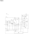
- the installation 100 firstly comprises an electrical network 102 comprising electrical sub-networks, two in the example described, designated by the references 104, 106.
- the electrical sub-networks 104, 106 are electrically disconnected from each other. and each include at least one piece of electrical equipment.
- the first electrical sub-network 104 comprises a battery 108, a device 110 for isolating the battery 108 and other electrical equipment 112, while the second electrical sub-network 106 comprises an electric motor 114 and another piece of electrical equipment 116.
- the electric motor 114 serves for example to drive a propeller (not shown) of the aircraft.
- the installation 100 further comprises a device 117 for connecting the subnetworks.
- the electrical network 102 may further comprise an electrical charging device 119 composed for example of one or more charging resistors, as well as a connection system 121 designed to selectively connect the electrical charging device 119 to a or more of the electrical subnetworks 104, 106.
- the connection system 121 comprises for example switches connecting the electrical charging device 119 respectively to at least some of the electrical subnetworks.
- the connection system 121 is designed to connect the electrical charging device 119 selectively to all the subnetworks 104, 106, and for this purpose comprises two respective switches.
- the installation 100 further comprises a turbogenerator 118 forming a propulsion system of the aircraft.
- the turbogenerator 118 firstly comprises a gas turbine 120 and a valve 123 for supplying fuel to the gas turbine 120.
- the turbogenerator 118 further comprises an electric generator 122 with permanent magnets designed to be mechanically driven by the gas turbine 120 by a rotation shaft 124.
- the electric generator 122 can be associated with a cooling system (not shown), for example forced air for low powers (typically less than 100 kW) and oil for higher powers.
- the electric generator 122 has groups of phases respectively connected to the electrical sub-networks.
- the electric generator 122 comprises two groups of phases 126, 128 respectively connected to the electrical sub-networks 104, 106.
- Each group of phases 126, 128 is carried by a stator of the electric generator 122
- the phases of each group of phases 126, 128 are for example organized in a star or in a triangle.
- Each phase generally includes a winding, also called a coil, designed to carry a phase current and to present a phase voltage.
- the turbogenerator 118 further comprises a system 129 for measuring operating parameters of the electric generator 122, such as the currents phase, phase voltages, phase temperatures and/or an oil temperature, in the case where the electric generator 122 is oil cooled.
- the electrical subnetworks 104, 106 use a direct voltage, called HVDC (from English “High Voltage Direct Current”), while the phase groups 126, 128 each provide alternating phase voltages .
- HVDC direct voltage
- the turbogenerator 118 comprises, for each group of phases 126, 128, an AC-DC voltage converter 130, 132 designed to convert the phase voltages of this group of phases 126, 128 into the HVDC voltage of the electrical sub-network 104, 106 associated.
- the turbogenerator 118 further comprises, for each group of phases 126, 128, an isolation device 134, 136 designed to disconnect the group of phases 126, 128 from its associated electrical sub-network 104, 106, and thus isolate this sub-network.
- -electrical network 104, 106 each isolation device 134, 136 comprises an electromechanical contactor, a pyrofuse or a Solid State Power Controller (Solid State Power Controller or SSPC).
- the turbogenerator 118 includes a speed sensor 138 designed to measure a rotational speed of the electric generator 122.
- the speed sensor 128 is for example mounted on the rotation shaft 124.
- the installation 100 further comprises a control device 140.
- control device 140 firstly comprises a unit 142 for controlling in particular the voltage converters 130, 132, generally called a Generator Control Unit (GCU). ).
- GCU Generator Control Unit
- the control device 140 further comprises a unit 144 for controlling in particular the gas turbine 120, generally called an Electronic Engine Control Unit (EECU) or Digital Authority Control. Full Authority Digital Engine Control (FADEC).
- EECU Electronic Engine Control Unit
- FADEC Full Authority Digital Engine Control
- the control device 140 further comprises a unit 146 for controlling in particular the electrical network 102, called the propulsion system supervisor.
- each of the modules 142, 144, 146 of the control device 140 comprises a computer system comprising a processing unit. processing (such as a microprocessor) and memory (such as main memory) into which a computer program is intended to be loaded, the computer program containing computer program instructions designed to be executed by the processing unit.
- processing such as a microprocessor
- memory such as main memory
- the functions implemented by the control device 140 which will be described subsequently, with reference to the method of figure 2 , are implemented in the example described in the computer program, in the form of software bricks.
- several of the modules 142, 144, 146 could be consolidated into a single computer system.
- all or part of these software bricks could be implemented in the form of hardware bricks, that is to say in the form of an electronic circuit, for example micro-wired, not involving a computer program.
- the GCU 142 detects a short circuit in at least one of the phase groups 126, 128.
- each phase group 126, 128 in which a short circuit is detected will be said to be defective and each other group of phases will be said to be healthy.
- each group of phases 126, 128 has the “healthy” status as long as the GCU 142 has not detected a short circuit in this group of phases 126, 128.
- a short circuit in a group of phases 126, 128 is most often due to an insulation fault in one or more windings.
- This short circuit results in a significant increase in the electric current circulating in the phases leading to very significant heating of the stator phases locally which can lead to the initiation of a fire, for example in the electrical and/or thermal insulation , and/or the ignition of the oil in the case where the electric generator 122 is cooled with oil.
- the risk of short circuit being generally constant per group of phases, the more groups of phases there are, the greater the overall risk.
- the GCU 142 detects a short circuit from measurements of phase currents, phase voltages and/or phase temperatures.
- the GCU 142 can also take into account the oil temperature measurement in order to avoid false short circuit detections (when the oil temperature measurement does not reveal abnormal oil heating) .
- the GCU 142 controls the isolation device associated with each defective phase group to disconnect this defective phase group from its associated electrical subnetwork. This electrical subnetwork thus becomes isolated from the defective group of phases. Additionally, the GCU 142 keeps each healthy phase group connected to its electrical subnetwork, leaving every other isolation device conducting (closed state).
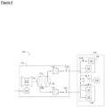
- the GCU 142 detects a short circuit in the phase group 126, we obtain the following situation illustrated in Figure 3 : the isolation device 134 is activated in the open state (insulating state) to isolate the electrical subnetwork 104 from the defective phase group 126 while the isolation device 136 is left in the closed state to maintain the healthy phase group 128 connected to its electrical subnetwork 106.
- the GCU 142 monitors the measurement of the rotation speed of the electric generator 122 provided by the sensor 138, to detect when the rotation speed is low enough to completely disconnect the electric generator 122 from the network electrical 102. For this, the GCU 142 detects for example if a predefined condition relating to the received rotation speed is met. This predefined condition is for example that the rotation speed falls below a predefined threshold or that it becomes zero.
- the GCU 142 disconnects all the phase groups 126, 128 from the electrical subnetworks 104, 106 by commanding the isolation device associated with each healthy phase group to disconnect this healthy phase group from its associated electrical subnetwork.
- the GCU 142 disconnects the healthy phase group 128 in step 208 by controlling the isolation device 136 to the state open (insulating state), as shown in the Figure 4 .
- the time during which each healthy group of phases is kept connected to its electrical subnetwork corresponds to the time that the rotation speed of the electrical generator 122 takes to reach the predefined condition.
- step 206 could be omitted and the hold time could be a fixed, predefined time.
- the GCU 142 sends an emergency stop request to the FADEC 144.
- the FADEC 144 commands a shutdown of the gas turbine 120.
- the FADEC 144 commands the closing of the fuel supply valve 123.
- step 204 of isolating one or more of the electrical sub-networks 104, 106 the electrical network 102 is modified, during a step 215, so that the electrical power that 'it takes from the electric generator 122 increases.
- Step 215 includes for example one or more of steps 216, 217 218 which will now be described.
- step 216 the Supervisor 146 (for example in response to an emergency stop request from the GCU) and/or the GCU 142 increases the electrical load of at least one piece of equipment. an electrical subnetwork associated with a healthy phase group, in order to increase the electrical power taken by the electrical network 102 from the electrical generator 122. Thus, if the healthy phase group(s) are not fully charged before the procedure emergency stop, step 216 has the effect of loading them more to further slow down the electric generator 122.
- the GCU 142 increases the HVDC voltage of the electrical subnetwork 104 to which the battery 108 belongs, so that the HVDC voltage becomes sufficiently higher than that of the battery 108 to impose a significant recharge current on it.
- This increase in voltage is for example achieved by appropriately controlling the voltage converter 130 of the electrical subnetwork 104 to which the battery 108 belongs.
- the increase in voltage 130 is preferably calculated by the GCU 142 so that the recharge current remains within the limits of operation of the battery 108 in particular lower than a maximum admissible recharge current, and to respect a maximum charge level of the battery 108.
- the Supervisor 146 controls the electric motor 114 in order to increase its rotation speed.
- Supervisor 146 controls the electric motor so that it generates a reactive current.
- this reactive current generates heating of the electric motor 114 without modifying its rotation speed.
- the additional electrical power consumed by the electric motor 114 is thus dissipated in the form of heat in the electric motor 114.
- the generation of the reactive current could be carried out in addition to the increase in the rotation speed.
- the electrical charging device 119 is used, for example in the case where the healthy phase group(s) are already charged to the maximum, in particular if for example the battery 108 is already charged to the maximum and that we do not want to modify the load of the electric motor 114 so as not to modify the aerodynamics of the flight.
- the connection system 119 is thus controlled by the control device 140 to connect the electrical charging device 119 to at least one electrical subnetwork associated with a healthy group of phases in order to increase the electrical power taken by this subnetwork electric.
- connection system 121 is controlled during step 217 to connect the electrical charging device 119 to the electrical subnetwork 106 associated with the healthy phase group 128.
- step 218 at least one electrical subnetwork isolated in step 204 is used to increase the electrical power taken from the electrical generator 122.
- the Supervisor 146 controls the connection device 117 to connect this isolated electrical subnetwork to the electrical subnetwork associated with a healthy phase group.
- the isolated electrical subnetwork is connected to the electrical generator 122 through the healthy phase group and can thus draw electrical power from the electrical generator 122.
- connection device 117 connects the isolated electrical sub-network 104 to the electrical generator 122 through the electrical sub-network 106, to be able to draw electrical power from it.
- the electrical load of the equipment in the previously isolated electrical subnetwork can then be increased, for example in the same manner as that described in step 216.
- the electrical load of the equipment 112, 108 of the electrical subnetwork 104 is for example increased during this step 220.
- the method 200 further comprises a step 222 prior to step 218, during which the Supervisor 146 controls the isolation device 110 of the battery 108 to isolate the battery 108 from the rest of the electrical subnetwork 104.
- the equipment(s) 112 other than the battery 108 can be used to increase the electrical power taken from the electrical generator 122.
- the isolation device 110 can be replaced by an accommodation device, which makes it possible to use the battery 108 to increase the electrical power taken from the electrical generator 122.
- the accommodation device includes, for example, a precharging resistor which limits the electrical current of the battery 108 until the voltages of the battery 108 and the electrical subnetwork 104 equalize.
- This precharging resistor is connected temporarily at the time of connection of the electrical subnetwork 104 to the electrical subnetwork 106, then disconnected when the voltages are equalized.
- the accommodation device comprises for example a DC-DC voltage converter which carries out the voltage adaptation between the battery 108 and the electrical sub-network 104.
- the voltage converter is generally present and active in permanence.
- the electric generator could have more than two groups of phases, connected to as many electrical sub-networks.
Landscapes
- Engineering & Computer Science (AREA)
- Aviation & Aerospace Engineering (AREA)
- Power Engineering (AREA)
- Mechanical Engineering (AREA)
- General Engineering & Computer Science (AREA)
- Control Of Eletrric Generators (AREA)
- Control Of Turbines (AREA)
Applications Claiming Priority (2)
| Application Number | Priority Date | Filing Date | Title |
|---|---|---|---|
| FR2006328A FR3111751B1 (fr) | 2020-06-17 | 2020-06-17 | Installation electromecanique d’aeronef avec turbogenerateur, procede d’arret d’urgence d’un turbogenerateur d’aeronef et programme d’ordinateur correspondant |
| PCT/FR2021/051055 WO2021255371A1 (fr) | 2020-06-17 | 2021-06-14 | Installation electromecanique d'aeronef avec turbogenerateur, procede d'arret d'urgence d'un turbogenerateur d'aeronef et programme d'ordinateur correspondant |
Publications (2)
| Publication Number | Publication Date |
|---|---|
| EP4169142A1 EP4169142A1 (fr) | 2023-04-26 |
| EP4169142B1 true EP4169142B1 (fr) | 2024-02-21 |
Family
ID=72356192
Family Applications (1)
| Application Number | Title | Priority Date | Filing Date |
|---|---|---|---|
| EP21737111.1A Active EP4169142B1 (fr) | 2020-06-17 | 2021-06-14 | Installation electromecanique d'aeronef avec turbogenerateur, procede d'arret d'urgence d'un turbogenerateur d'aeronef et programme d'ordinateur correspondant |
Country Status (7)
| Country | Link |
|---|---|
| US (1) | US20230138626A1 (pl) |
| EP (1) | EP4169142B1 (pl) |
| CN (1) | CN115699499A (pl) |
| CA (1) | CA3182186A1 (pl) |
| FR (1) | FR3111751B1 (pl) |
| PL (1) | PL4169142T3 (pl) |
| WO (1) | WO2021255371A1 (pl) |
Families Citing this family (1)
| Publication number | Priority date | Publication date | Assignee | Title |
|---|---|---|---|---|
| FR3149042B1 (fr) * | 2023-05-23 | 2025-10-10 | Safran Helicopter Engines | Procede d’arret d’une turbomachine d’aeronef en cas d’incendie dans le compartiment de la turbomachine |
Family Cites Families (8)
| Publication number | Priority date | Publication date | Assignee | Title |
|---|---|---|---|---|
| US7583063B2 (en) * | 2003-05-27 | 2009-09-01 | Pratt & Whitney Canada Corp. | Architecture for electric machine |
| US7876542B2 (en) * | 2007-08-16 | 2011-01-25 | Hamilton Sundstrand Corporation | Generator for gas turbine engine having DC bus fault short circuit control using a battery |
| US8237416B2 (en) * | 2008-12-09 | 2012-08-07 | Hamilton Sundstrand Corporation | More electric engine with regulated permanent magnet machines |
| GB0921323D0 (en) * | 2009-12-07 | 2010-01-20 | Rolls Royce Plc | An electrical machine |
| US9698593B2 (en) * | 2012-11-20 | 2017-07-04 | Vestas Wind Systems A/S | Methods and systems for reducing the impact of a generator short circuit in a wind turbine |
| US10006375B1 (en) * | 2017-07-11 | 2018-06-26 | General Electric Company | Propulsion system for an aircraft |
| EP3522362B1 (en) * | 2018-02-01 | 2023-12-20 | Siemens Gamesa Renewable Energy A/S | Controlling a multi winding set permanent magnet electrical machine |
| FR3084340B1 (fr) * | 2018-07-27 | 2022-05-06 | Safran | Systeme de generation de puissance electrique pour aeronef |
-
2020
- 2020-06-17 FR FR2006328A patent/FR3111751B1/fr active Active
-
2021
- 2021-06-14 EP EP21737111.1A patent/EP4169142B1/fr active Active
- 2021-06-14 PL PL21737111.1T patent/PL4169142T3/pl unknown
- 2021-06-14 CN CN202180042228.5A patent/CN115699499A/zh active Pending
- 2021-06-14 CA CA3182186A patent/CA3182186A1/en active Pending
- 2021-06-14 US US18/000,885 patent/US20230138626A1/en active Pending
- 2021-06-14 WO PCT/FR2021/051055 patent/WO2021255371A1/fr not_active Ceased
Also Published As
| Publication number | Publication date |
|---|---|
| PL4169142T3 (pl) | 2024-05-06 |
| EP4169142A1 (fr) | 2023-04-26 |
| FR3111751A1 (fr) | 2021-12-24 |
| CA3182186A1 (en) | 2021-12-23 |
| CN115699499A (zh) | 2023-02-03 |
| FR3111751B1 (fr) | 2022-06-03 |
| WO2021255371A1 (fr) | 2021-12-23 |
| US20230138626A1 (en) | 2023-05-04 |
Similar Documents
| Publication | Publication Date | Title |
|---|---|---|
| EP3365970B1 (fr) | Démarreur-générateur de turbomachine a machine électrique asynchrone multi-enroulements | |
| FR2719170A1 (fr) | Système et procédé de recharge de batterie. | |
| EP3700053A1 (fr) | Système et procédé de précharge d'un condensateur par une batterie comportant une résistance de précharge et un dispositif hacheur | |
| EP4169142B1 (fr) | Installation electromecanique d'aeronef avec turbogenerateur, procede d'arret d'urgence d'un turbogenerateur d'aeronef et programme d'ordinateur correspondant | |
| FR2825852A1 (fr) | Systeme de commande de moteur a combustion interne pour vehicule et procede de commande associe | |
| FR3099134A1 (fr) | Procédé d’alimentation électrique d’un réseau électrique et architecture électrique | |
| EP3956227B1 (fr) | Procéde de commande d'un réseau d'alimentation électrique d'un aéronef | |
| EP4441862B1 (fr) | Procede de refroidissement optimise d'une batterie de vehicule electrique ou hybride | |
| EP4476806B1 (fr) | Unité de commande de la puissance d'au moins une batterie, aéronef comprenant ladite unité de commande et procédé de commande correspondant | |
| WO2017109323A1 (fr) | Dispositif de contrôle d'un convertisseur dc/dc en présence d'une surtension ou sous-tension dans un circuit électrique | |
| FR2896105B1 (fr) | Systeme de commande d'entrainement pour un moteur-generateur de vehicule | |
| WO2024121485A1 (fr) | Système propulsif électrique d'aéronef à tolérance de pannes | |
| FR3011132A3 (fr) | Dispositif de chauffage d'une batterie dans une chaine de traction electrique pour vehicule automobile hybride | |
| FR3127201A1 (fr) | Système de turbomachine hybride | |
| EP3694091A1 (fr) | Procédé et système de protection d'un circuit d'alimentation électrique | |
| EP2622206A2 (fr) | Procede de gestion de l'arret et du redemarrage automatique d'un moteur thermique de vehicule automobile et vehicule automobile correspondant | |
| FR2963766A1 (fr) | Procede de fonctionnement d'un systeme de charge de batteries d'alimentation de moteurs d'entrainement de vehicules automobiles. | |
| WO2015091222A1 (fr) | Pompe primaire d'un reacteur nucleaire | |
| EP4567266A1 (fr) | Installation motrice munie d'un turbomoteur et d'un circuit de demarrage adaptatif et procede de demarrage adaptatif d'un turbomoteur | |
| FR3132601A1 (fr) | Procede d’arret d’une generatrice electrique a aimants permanents par demagnetisation | |
| FR3150313A1 (fr) | Procede de gestion du courant d’alimentation d’un actionneur electrique | |
| FR3143912A1 (fr) | Système de commande d’un convertisseur de tension | |
| WO2026074239A1 (fr) | Système de distribution électrique pour aéronef | |
| WO2020157394A1 (fr) | Procede de pilotage d'un generateur couple a une roue-libre d'un vehicule automobile | |
| FR3000850A1 (fr) | Procede et dispositif de controle d'une consigne interne de courant d'un producteur d'energie electrique pendant un mode de fonctionnement degrade |
Legal Events
| Date | Code | Title | Description |
|---|---|---|---|
| STAA | Information on the status of an ep patent application or granted ep patent |
Free format text: STATUS: UNKNOWN |
|
| STAA | Information on the status of an ep patent application or granted ep patent |
Free format text: STATUS: THE INTERNATIONAL PUBLICATION HAS BEEN MADE |
|
| PUAI | Public reference made under article 153(3) epc to a published international application that has entered the european phase |
Free format text: ORIGINAL CODE: 0009012 |
|
| STAA | Information on the status of an ep patent application or granted ep patent |
Free format text: STATUS: REQUEST FOR EXAMINATION WAS MADE |
|
| 17P | Request for examination filed |
Effective date: 20221212 |
|
| AK | Designated contracting states |
Kind code of ref document: A1 Designated state(s): AL AT BE BG CH CY CZ DE DK EE ES FI FR GB GR HR HU IE IS IT LI LT LU LV MC MK MT NL NO PL PT RO RS SE SI SK SM TR |
|
| DAV | Request for validation of the european patent (deleted) | ||
| DAX | Request for extension of the european patent (deleted) | ||
| GRAP | Despatch of communication of intention to grant a patent |
Free format text: ORIGINAL CODE: EPIDOSNIGR1 |
|
| STAA | Information on the status of an ep patent application or granted ep patent |
Free format text: STATUS: GRANT OF PATENT IS INTENDED |
|
| RIC1 | Information provided on ipc code assigned before grant |
Ipc: B64D 27/02 20060101ALN20230929BHEP Ipc: F01D 21/00 20060101ALN20230929BHEP Ipc: F01D 15/10 20060101ALN20230929BHEP Ipc: H02P 9/48 20060101ALI20230929BHEP Ipc: H02H 7/06 20060101ALI20230929BHEP Ipc: B64D 41/00 20060101ALI20230929BHEP Ipc: H02J 4/00 20060101AFI20230929BHEP |
|
| INTG | Intention to grant announced |
Effective date: 20231016 |
|
| GRAS | Grant fee paid |
Free format text: ORIGINAL CODE: EPIDOSNIGR3 |
|
| GRAA | (expected) grant |
Free format text: ORIGINAL CODE: 0009210 |
|
| STAA | Information on the status of an ep patent application or granted ep patent |
Free format text: STATUS: THE PATENT HAS BEEN GRANTED |
|
| AK | Designated contracting states |
Kind code of ref document: B1 Designated state(s): AL AT BE BG CH CY CZ DE DK EE ES FI FR GB GR HR HU IE IS IT LI LT LU LV MC MK MT NL NO PL PT RO RS SE SI SK SM TR |
|
| RAP3 | Party data changed (applicant data changed or rights of an application transferred) |
Owner name: SAFRAN HELICOPTER ENGINES |
|
| REG | Reference to a national code |
Ref country code: GB Ref legal event code: FG4D Free format text: NOT ENGLISH |
|
| REG | Reference to a national code |
Ref country code: CH Ref legal event code: EP |
|
| REG | Reference to a national code |
Ref country code: IE Ref legal event code: FG4D Free format text: LANGUAGE OF EP DOCUMENT: FRENCH |
|
| REG | Reference to a national code |
Ref country code: DE Ref legal event code: R096 Ref document number: 602021009663 Country of ref document: DE |
|
| REG | Reference to a national code |
Ref country code: LT Ref legal event code: MG9D |
|
| REG | Reference to a national code |
Ref country code: NL Ref legal event code: MP Effective date: 20240221 |
|
| PG25 | Lapsed in a contracting state [announced via postgrant information from national office to epo] |
Ref country code: IS Free format text: LAPSE BECAUSE OF FAILURE TO SUBMIT A TRANSLATION OF THE DESCRIPTION OR TO PAY THE FEE WITHIN THE PRESCRIBED TIME-LIMIT Effective date: 20240621 |
|
| PG25 | Lapsed in a contracting state [announced via postgrant information from national office to epo] |
Ref country code: LT Free format text: LAPSE BECAUSE OF FAILURE TO SUBMIT A TRANSLATION OF THE DESCRIPTION OR TO PAY THE FEE WITHIN THE PRESCRIBED TIME-LIMIT Effective date: 20240221 |
|
| PG25 | Lapsed in a contracting state [announced via postgrant information from national office to epo] |
Ref country code: GR Free format text: LAPSE BECAUSE OF FAILURE TO SUBMIT A TRANSLATION OF THE DESCRIPTION OR TO PAY THE FEE WITHIN THE PRESCRIBED TIME-LIMIT Effective date: 20240522 |
|
| REG | Reference to a national code |
Ref country code: AT Ref legal event code: MK05 Ref document number: 1659962 Country of ref document: AT Kind code of ref document: T Effective date: 20240221 |
|
| PG25 | Lapsed in a contracting state [announced via postgrant information from national office to epo] |
Ref country code: NL Free format text: LAPSE BECAUSE OF FAILURE TO SUBMIT A TRANSLATION OF THE DESCRIPTION OR TO PAY THE FEE WITHIN THE PRESCRIBED TIME-LIMIT Effective date: 20240221 Ref country code: RS Free format text: LAPSE BECAUSE OF FAILURE TO SUBMIT A TRANSLATION OF THE DESCRIPTION OR TO PAY THE FEE WITHIN THE PRESCRIBED TIME-LIMIT Effective date: 20240521 Ref country code: HR Free format text: LAPSE BECAUSE OF FAILURE TO SUBMIT A TRANSLATION OF THE DESCRIPTION OR TO PAY THE FEE WITHIN THE PRESCRIBED TIME-LIMIT Effective date: 20240221 |
|
| PG25 | Lapsed in a contracting state [announced via postgrant information from national office to epo] |
Ref country code: ES Free format text: LAPSE BECAUSE OF FAILURE TO SUBMIT A TRANSLATION OF THE DESCRIPTION OR TO PAY THE FEE WITHIN THE PRESCRIBED TIME-LIMIT Effective date: 20240221 |
|
| PG25 | Lapsed in a contracting state [announced via postgrant information from national office to epo] |
Ref country code: AT Free format text: LAPSE BECAUSE OF FAILURE TO SUBMIT A TRANSLATION OF THE DESCRIPTION OR TO PAY THE FEE WITHIN THE PRESCRIBED TIME-LIMIT Effective date: 20240221 |
|
| PG25 | Lapsed in a contracting state [announced via postgrant information from national office to epo] |
Ref country code: RS Free format text: LAPSE BECAUSE OF FAILURE TO SUBMIT A TRANSLATION OF THE DESCRIPTION OR TO PAY THE FEE WITHIN THE PRESCRIBED TIME-LIMIT Effective date: 20240521 Ref country code: NO Free format text: LAPSE BECAUSE OF FAILURE TO SUBMIT A TRANSLATION OF THE DESCRIPTION OR TO PAY THE FEE WITHIN THE PRESCRIBED TIME-LIMIT Effective date: 20240521 Ref country code: NL Free format text: LAPSE BECAUSE OF FAILURE TO SUBMIT A TRANSLATION OF THE DESCRIPTION OR TO PAY THE FEE WITHIN THE PRESCRIBED TIME-LIMIT Effective date: 20240221 Ref country code: LT Free format text: LAPSE BECAUSE OF FAILURE TO SUBMIT A TRANSLATION OF THE DESCRIPTION OR TO PAY THE FEE WITHIN THE PRESCRIBED TIME-LIMIT Effective date: 20240221 Ref country code: IS Free format text: LAPSE BECAUSE OF FAILURE TO SUBMIT A TRANSLATION OF THE DESCRIPTION OR TO PAY THE FEE WITHIN THE PRESCRIBED TIME-LIMIT Effective date: 20240621 Ref country code: HR Free format text: LAPSE BECAUSE OF FAILURE TO SUBMIT A TRANSLATION OF THE DESCRIPTION OR TO PAY THE FEE WITHIN THE PRESCRIBED TIME-LIMIT Effective date: 20240221 Ref country code: GR Free format text: LAPSE BECAUSE OF FAILURE TO SUBMIT A TRANSLATION OF THE DESCRIPTION OR TO PAY THE FEE WITHIN THE PRESCRIBED TIME-LIMIT Effective date: 20240522 Ref country code: FI Free format text: LAPSE BECAUSE OF FAILURE TO SUBMIT A TRANSLATION OF THE DESCRIPTION OR TO PAY THE FEE WITHIN THE PRESCRIBED TIME-LIMIT Effective date: 20240221 Ref country code: ES Free format text: LAPSE BECAUSE OF FAILURE TO SUBMIT A TRANSLATION OF THE DESCRIPTION OR TO PAY THE FEE WITHIN THE PRESCRIBED TIME-LIMIT Effective date: 20240221 Ref country code: BG Free format text: LAPSE BECAUSE OF FAILURE TO SUBMIT A TRANSLATION OF THE DESCRIPTION OR TO PAY THE FEE WITHIN THE PRESCRIBED TIME-LIMIT Effective date: 20240221 Ref country code: AT Free format text: LAPSE BECAUSE OF FAILURE TO SUBMIT A TRANSLATION OF THE DESCRIPTION OR TO PAY THE FEE WITHIN THE PRESCRIBED TIME-LIMIT Effective date: 20240221 |
|
| PG25 | Lapsed in a contracting state [announced via postgrant information from national office to epo] |
Ref country code: PT Free format text: LAPSE BECAUSE OF FAILURE TO SUBMIT A TRANSLATION OF THE DESCRIPTION OR TO PAY THE FEE WITHIN THE PRESCRIBED TIME-LIMIT Effective date: 20240621 |
|
| PG25 | Lapsed in a contracting state [announced via postgrant information from national office to epo] |
Ref country code: SE Free format text: LAPSE BECAUSE OF FAILURE TO SUBMIT A TRANSLATION OF THE DESCRIPTION OR TO PAY THE FEE WITHIN THE PRESCRIBED TIME-LIMIT Effective date: 20240221 Ref country code: PT Free format text: LAPSE BECAUSE OF FAILURE TO SUBMIT A TRANSLATION OF THE DESCRIPTION OR TO PAY THE FEE WITHIN THE PRESCRIBED TIME-LIMIT Effective date: 20240621 Ref country code: LV Free format text: LAPSE BECAUSE OF FAILURE TO SUBMIT A TRANSLATION OF THE DESCRIPTION OR TO PAY THE FEE WITHIN THE PRESCRIBED TIME-LIMIT Effective date: 20240221 |
|
| PG25 | Lapsed in a contracting state [announced via postgrant information from national office to epo] |
Ref country code: DK Free format text: LAPSE BECAUSE OF FAILURE TO SUBMIT A TRANSLATION OF THE DESCRIPTION OR TO PAY THE FEE WITHIN THE PRESCRIBED TIME-LIMIT Effective date: 20240221 |
|
| PG25 | Lapsed in a contracting state [announced via postgrant information from national office to epo] |
Ref country code: SM Free format text: LAPSE BECAUSE OF FAILURE TO SUBMIT A TRANSLATION OF THE DESCRIPTION OR TO PAY THE FEE WITHIN THE PRESCRIBED TIME-LIMIT Effective date: 20240221 |
|
| PG25 | Lapsed in a contracting state [announced via postgrant information from national office to epo] |
Ref country code: EE Free format text: LAPSE BECAUSE OF FAILURE TO SUBMIT A TRANSLATION OF THE DESCRIPTION OR TO PAY THE FEE WITHIN THE PRESCRIBED TIME-LIMIT Effective date: 20240221 |
|
| PG25 | Lapsed in a contracting state [announced via postgrant information from national office to epo] |
Ref country code: SK Free format text: LAPSE BECAUSE OF FAILURE TO SUBMIT A TRANSLATION OF THE DESCRIPTION OR TO PAY THE FEE WITHIN THE PRESCRIBED TIME-LIMIT Effective date: 20240221 |
|
| PG25 | Lapsed in a contracting state [announced via postgrant information from national office to epo] |
Ref country code: SM Free format text: LAPSE BECAUSE OF FAILURE TO SUBMIT A TRANSLATION OF THE DESCRIPTION OR TO PAY THE FEE WITHIN THE PRESCRIBED TIME-LIMIT Effective date: 20240221 Ref country code: SK Free format text: LAPSE BECAUSE OF FAILURE TO SUBMIT A TRANSLATION OF THE DESCRIPTION OR TO PAY THE FEE WITHIN THE PRESCRIBED TIME-LIMIT Effective date: 20240221 Ref country code: RO Free format text: LAPSE BECAUSE OF FAILURE TO SUBMIT A TRANSLATION OF THE DESCRIPTION OR TO PAY THE FEE WITHIN THE PRESCRIBED TIME-LIMIT Effective date: 20240221 Ref country code: EE Free format text: LAPSE BECAUSE OF FAILURE TO SUBMIT A TRANSLATION OF THE DESCRIPTION OR TO PAY THE FEE WITHIN THE PRESCRIBED TIME-LIMIT Effective date: 20240221 Ref country code: DK Free format text: LAPSE BECAUSE OF FAILURE TO SUBMIT A TRANSLATION OF THE DESCRIPTION OR TO PAY THE FEE WITHIN THE PRESCRIBED TIME-LIMIT Effective date: 20240221 |
|
| REG | Reference to a national code |
Ref country code: DE Ref legal event code: R097 Ref document number: 602021009663 Country of ref document: DE |
|
| PLBE | No opposition filed within time limit |
Free format text: ORIGINAL CODE: 0009261 |
|
| STAA | Information on the status of an ep patent application or granted ep patent |
Free format text: STATUS: NO OPPOSITION FILED WITHIN TIME LIMIT |
|
| 26N | No opposition filed |
Effective date: 20241122 |
|
| PG25 | Lapsed in a contracting state [announced via postgrant information from national office to epo] |
Ref country code: MC Free format text: LAPSE BECAUSE OF FAILURE TO SUBMIT A TRANSLATION OF THE DESCRIPTION OR TO PAY THE FEE WITHIN THE PRESCRIBED TIME-LIMIT Effective date: 20240221 |
|
| REG | Reference to a national code |
Ref country code: CH Ref legal event code: PL |
|
| PG25 | Lapsed in a contracting state [announced via postgrant information from national office to epo] |
Ref country code: LU Free format text: LAPSE BECAUSE OF NON-PAYMENT OF DUE FEES Effective date: 20240614 |
|
| PG25 | Lapsed in a contracting state [announced via postgrant information from national office to epo] |
Ref country code: IE Free format text: LAPSE BECAUSE OF NON-PAYMENT OF DUE FEES Effective date: 20240614 |
|
| PG25 | Lapsed in a contracting state [announced via postgrant information from national office to epo] |
Ref country code: SI Free format text: LAPSE BECAUSE OF FAILURE TO SUBMIT A TRANSLATION OF THE DESCRIPTION OR TO PAY THE FEE WITHIN THE PRESCRIBED TIME-LIMIT Effective date: 20240221 Ref country code: BE Free format text: LAPSE BECAUSE OF NON-PAYMENT OF DUE FEES Effective date: 20240630 Ref country code: CH Free format text: LAPSE BECAUSE OF NON-PAYMENT OF DUE FEES Effective date: 20240630 |
|
| REG | Reference to a national code |
Ref country code: BE Ref legal event code: MM Effective date: 20240630 |
|
| PGFP | Annual fee paid to national office [announced via postgrant information from national office to epo] |
Ref country code: PL Payment date: 20250604 Year of fee payment: 5 Ref country code: DE Payment date: 20250618 Year of fee payment: 5 |
|
| PGFP | Annual fee paid to national office [announced via postgrant information from national office to epo] |
Ref country code: GB Payment date: 20250625 Year of fee payment: 5 |
|
| PGFP | Annual fee paid to national office [announced via postgrant information from national office to epo] |
Ref country code: FR Payment date: 20250620 Year of fee payment: 5 |
|
| PGFP | Annual fee paid to national office [announced via postgrant information from national office to epo] |
Ref country code: CZ Payment date: 20250530 Year of fee payment: 5 |
|
| PGFP | Annual fee paid to national office [announced via postgrant information from national office to epo] |
Ref country code: IT Payment date: 20250630 Year of fee payment: 5 |
|
| PG25 | Lapsed in a contracting state [announced via postgrant information from national office to epo] |
Ref country code: CY Free format text: LAPSE BECAUSE OF FAILURE TO SUBMIT A TRANSLATION OF THE DESCRIPTION OR TO PAY THE FEE WITHIN THE PRESCRIBED TIME-LIMIT; INVALID AB INITIO Effective date: 20210614 |
|
| PG25 | Lapsed in a contracting state [announced via postgrant information from national office to epo] |
Ref country code: HU Free format text: LAPSE BECAUSE OF FAILURE TO SUBMIT A TRANSLATION OF THE DESCRIPTION OR TO PAY THE FEE WITHIN THE PRESCRIBED TIME-LIMIT; INVALID AB INITIO Effective date: 20210614 |