EP4168656B1 - Anlage und verfahren zur energieverwaltung - Google Patents
Anlage und verfahren zur energieverwaltung Download PDFInfo
- Publication number
- EP4168656B1 EP4168656B1 EP21737493.3A EP21737493A EP4168656B1 EP 4168656 B1 EP4168656 B1 EP 4168656B1 EP 21737493 A EP21737493 A EP 21737493A EP 4168656 B1 EP4168656 B1 EP 4168656B1
- Authority
- EP
- European Patent Office
- Prior art keywords
- working fluid
- combustion
- plant
- heat
- tank
- Prior art date
- Legal status (The legal status is an assumption and is not a legal conclusion. Google has not performed a legal analysis and makes no representation as to the accuracy of the status listed.)
- Active
Links
Images


Classifications
-
- F—MECHANICAL ENGINEERING; LIGHTING; HEATING; WEAPONS; BLASTING
- F01—MACHINES OR ENGINES IN GENERAL; ENGINE PLANTS IN GENERAL; STEAM ENGINES
- F01K—STEAM ENGINE PLANTS; STEAM ACCUMULATORS; ENGINE PLANTS NOT OTHERWISE PROVIDED FOR; ENGINES USING SPECIAL WORKING FLUIDS OR CYCLES
- F01K13/00—General layout or general methods of operation of complete plants
- F01K13/02—Controlling, e.g. stopping or starting
-
- F—MECHANICAL ENGINEERING; LIGHTING; HEATING; WEAPONS; BLASTING
- F01—MACHINES OR ENGINES IN GENERAL; ENGINE PLANTS IN GENERAL; STEAM ENGINES
- F01K—STEAM ENGINE PLANTS; STEAM ACCUMULATORS; ENGINE PLANTS NOT OTHERWISE PROVIDED FOR; ENGINES USING SPECIAL WORKING FLUIDS OR CYCLES
- F01K25/00—Plants or engines characterised by use of special working fluids, not otherwise provided for; Plants operating in closed cycles and not otherwise provided for
- F01K25/06—Plants or engines characterised by use of special working fluids, not otherwise provided for; Plants operating in closed cycles and not otherwise provided for using mixtures of different fluids
-
- F—MECHANICAL ENGINEERING; LIGHTING; HEATING; WEAPONS; BLASTING
- F01—MACHINES OR ENGINES IN GENERAL; ENGINE PLANTS IN GENERAL; STEAM ENGINES
- F01K—STEAM ENGINE PLANTS; STEAM ACCUMULATORS; ENGINE PLANTS NOT OTHERWISE PROVIDED FOR; ENGINES USING SPECIAL WORKING FLUIDS OR CYCLES
- F01K25/00—Plants or engines characterised by use of special working fluids, not otherwise provided for; Plants operating in closed cycles and not otherwise provided for
- F01K25/08—Plants or engines characterised by use of special working fluids, not otherwise provided for; Plants operating in closed cycles and not otherwise provided for using special vapours
- F01K25/10—Plants or engines characterised by use of special working fluids, not otherwise provided for; Plants operating in closed cycles and not otherwise provided for using special vapours the vapours being cold, e.g. ammonia, carbon dioxide, ether
-
- F—MECHANICAL ENGINEERING; LIGHTING; HEATING; WEAPONS; BLASTING
- F01—MACHINES OR ENGINES IN GENERAL; ENGINE PLANTS IN GENERAL; STEAM ENGINES
- F01K—STEAM ENGINE PLANTS; STEAM ACCUMULATORS; ENGINE PLANTS NOT OTHERWISE PROVIDED FOR; ENGINES USING SPECIAL WORKING FLUIDS OR CYCLES
- F01K3/00—Plants characterised by the use of steam or heat accumulators, or intermediate steam heaters, therein
- F01K3/12—Plants characterised by the use of steam or heat accumulators, or intermediate steam heaters, therein having two or more accumulators
-
- F—MECHANICAL ENGINEERING; LIGHTING; HEATING; WEAPONS; BLASTING
- F01—MACHINES OR ENGINES IN GENERAL; ENGINE PLANTS IN GENERAL; STEAM ENGINES
- F01K—STEAM ENGINE PLANTS; STEAM ACCUMULATORS; ENGINE PLANTS NOT OTHERWISE PROVIDED FOR; ENGINES USING SPECIAL WORKING FLUIDS OR CYCLES
- F01K3/00—Plants characterised by the use of steam or heat accumulators, or intermediate steam heaters, therein
- F01K3/14—Plants characterised by the use of steam or heat accumulators, or intermediate steam heaters, therein having both steam accumulator and heater, e.g. superheating accumulator
-
- F—MECHANICAL ENGINEERING; LIGHTING; HEATING; WEAPONS; BLASTING
- F01—MACHINES OR ENGINES IN GENERAL; ENGINE PLANTS IN GENERAL; STEAM ENGINES
- F01K—STEAM ENGINE PLANTS; STEAM ACCUMULATORS; ENGINE PLANTS NOT OTHERWISE PROVIDED FOR; ENGINES USING SPECIAL WORKING FLUIDS OR CYCLES
- F01K7/00—Steam engine plants characterised by the use of specific types of engine; Plants or engines characterised by their use of special steam systems, cycles or processes; Control means specially adapted for such systems, cycles or processes; Use of withdrawn or exhaust steam for feed-water heating
- F01K7/32—Steam engine plants characterised by the use of specific types of engine; Plants or engines characterised by their use of special steam systems, cycles or processes; Control means specially adapted for such systems, cycles or processes; Use of withdrawn or exhaust steam for feed-water heating the engines using steam of critical or overcritical pressure
-
- F—MECHANICAL ENGINEERING; LIGHTING; HEATING; WEAPONS; BLASTING
- F02—COMBUSTION ENGINES; HOT-GAS OR COMBUSTION-PRODUCT ENGINE PLANTS
- F02C—GAS-TURBINE PLANTS; AIR INTAKES FOR JET-PROPULSION PLANTS; CONTROLLING FUEL SUPPLY IN AIR-BREATHING JET-PROPULSION PLANTS
- F02C1/00—Gas-turbine plants characterised by the use of hot gases or unheated pressurised gases, as the working fluid
- F02C1/04—Gas-turbine plants characterised by the use of hot gases or unheated pressurised gases, as the working fluid the working fluid being heated indirectly
- F02C1/10—Closed cycles
-
- Y—GENERAL TAGGING OF NEW TECHNOLOGICAL DEVELOPMENTS; GENERAL TAGGING OF CROSS-SECTIONAL TECHNOLOGIES SPANNING OVER SEVERAL SECTIONS OF THE IPC; TECHNICAL SUBJECTS COVERED BY FORMER USPC CROSS-REFERENCE ART COLLECTIONS [XRACs] AND DIGESTS
- Y02—TECHNOLOGIES OR APPLICATIONS FOR MITIGATION OR ADAPTATION AGAINST CLIMATE CHANGE
- Y02E—REDUCTION OF GREENHOUSE GAS [GHG] EMISSIONS, RELATED TO ENERGY GENERATION, TRANSMISSION OR DISTRIBUTION
- Y02E20/00—Combustion technologies with mitigation potential
- Y02E20/34—Indirect CO2mitigation, i.e. by acting on non CO2directly related matters of the process, e.g. pre-heating or heat recovery
Definitions
- the object of the present invention is a plant and a process for energy management, where with management it is intended the generation, the transformation, the absorption and the storage of energy.
- the object of the present invention is a system capable of generating energy, absorbing/using energy, maintaining the energy stored over time and capable of retransforming it into energy, for example thermal, mechanical and/or electrical.
- the present invention relates to a system for generating energy by means of oxy-combustion and from possible further sources and for storing energy in the form of potential energy (pressure) and thermal/thermodynamic energy, through the actuation of a thermodynamic cycle and/or of a cyclic thermodynamic transformation.
- the present invention is also situated in the field of systems for capture and sequester (CCS) of the carbon dioxide (CO 2 ) from oxy-combustion or from other sources.
- CCS capture and sequester
- the present invention is situated for example in the field of systems of generation from various sources and for storing energy of medium and large scale, for both land and sea applications, typically with powers ranging from hundreds of kW to tens of MW (e.g. 20-25MW), but also hundreds of MW, and with storage capacities ranging from a few hundred kWh to hundreds of MWh and even up to several GWh.
- powers ranging from hundreds of kW to tens of MW (e.g. 20-25MW), but also hundreds of MW, and with storage capacities ranging from a few hundred kWh to hundreds of MWh and even up to several GWh.
- the present invention can also be situated in the field of systems of generation from various sources and for storing energy of small scale, for home and commercial applications, both land and sea, typically with powers ranging from a few kW to several hundred kW and with storage capacity from a few kWh up to hundreds of kWh.
- the public document WO/2020/039416 in the name of the same Applicant, illustrates an energy storage plant and process.
- the plant comprises a casing for the storage of a working fluid other than atmospheric air, in gaseous phase and in equilibrium of pressure with the atmosphere; a tank for the storage of such working fluid in liquid or supercritical phase with a temperature close to the critical temperature, in which the critical temperature is close to the ambient temperature.
- the plant is configured to perform a closed cyclic thermodynamic transformation, first in one direction in a charge configuration and then in an opposite direction in a discharge configuration, between the casing and the tank. In the charge configuration the plant stores heat and pressure and in the discharge configuration the plant generates energy.
- the Applicant has in particular felt the need to make a system (plant and process) for generation, absorption, transformation and storage of energy (Energy Storage) such to allow managing (generating, accumulating, absorbing, transforming, switching) the energy coming from various sources (non-renewable sources and fuels, such as fossil fuels, and renewable and even synthetic sources and fuels) in a flexible, efficient and effective manner.
- sources non-renewable sources and fuels, such as fossil fuels, and renewable and even synthetic sources and fuels
- the Applicant has also set as objective to ideate and make a system that allows generating and converting energy without introducing carbon dioxide CO 2 into the atmosphere or even contributing to the reduction thereof, i.e. absorbing CO 2 produced by other industrial processes.
- the present invention regards a plant for energy management, comprising:
- the present invention regards a process for energy management, comprising:
- the process is actuated with the plant according to the preceding aspect and/or according to one or more of the following aspects.
- the working fluid has the following chemical-physical properties: critical temperature comprised between 0°C and 200°C, density a 25°C comprised between 0.5 kg/m 3 and 10 kg/m 3 .
- the working fluid comprises or consists of CO 2 and/or N 2 O.
- the working fluid is a mixture of gas comprising CO 2 and/or N 2 O.
- the products generated by the oxy-combustion comprise CO 2 and/or N 2 O.
- the Applicant has verified that the plant and the process according to the invention allow obtaining the pre-established objectives.
- the Applicant has verified that the invention allows managing the absorbed, stored, returned and generated energy in a flexible and effective manner.
- the Applicant has verified that the invention allows using and/or storing products, like carbon dioxide CO 2 or nitrogen oxide N 2 O, coming from other processes.
- the Applicant has in particular verified that the invention allows automatically capturing CO 2 from an existing process and it makes it available for storage or other aims and simultaneously generates energy with the possibility of storing it.
- the plant and process according to the invention can be integrated with pre-existing plants/industrial processes, rendering the capture of CO 2 intrinsic.
- the Applicant has verified that the invention allows generating and converting energy without introducing carbon dioxide into the atmosphere or even contributing to the reduction thereof.
- the Applicant has in particular verified that the plant and/or process according to the present invention can be integrated with plants/industrial processes which produce gas and can use and/or capture such gas products.
- the expander comprises at least one expansion turbine.
- the compressor comprises at least one turbocharger.
- said at least one expander comprises a plurality of expanders arranged in series.
- said at least one compressor is of the type with or without inter-cooling.
- said at least one compressor comprises a plurality of compressors arranged in series, with or without inter-cooling between said compressors.
- said at least one combustion chamber is placed upstream of the expanders and/or between the expanders.
- said at least one combustion chamber is part of a turbomachine comprising said turbine and said turbocharger.
- the combustion chamber is configured to receive, directly or indirectly, a fuel and oxygen.
- provision is made for introducing fuel and oxygen directly or indirectly into the combustion chamber in which the working fluid flows.
- the combustion chamber has an inlet for the fuel and/or for the oxygen.
- the fuel is introduced in a suction of said at least one compressor or of an auxiliary compressor dedicated for such purpose, optionally at atmospheric pressure.
- the oxygen is compressed, optionally by means of a dedicated compressor, before being introduced.
- the fuel comprises products containing carbon.
- the fuel comprises products containing nitrogen.
- the fuel is selected from the group comprising: methane and other fossil fuels, LNG, synthetic fuels such as SNG (Synthetic Natural Gas), LSF, ammonia NH 3 , hydrazine, urea.
- LNG synthetic fuels
- SNG Synthetic Natural Gas
- LSF ammonia NH 3
- hydrazine urea
- the fuel comprises gas resulting from industrial processes, e.g. steel-making processes such as BFG (Blast Furnace Gas), Converter Gas like LDG (Linz-Donawitz Converter Gas), or process gas from Direct Reduce Iron.
- BFG Blast Furnace Gas
- Converter Gas like LDG (Linz-Donawitz Converter Gas)
- process gas from Direct Reduce Iron.
- another object of the present invention is a steel plant comprising or operationally associated with a plant for energy management according to the present invention and/or a steel-making process comprising or operationally associated with a process for energy management according to the present invention, in which the gases produced by said steel plant and/or resulting from said steel-making process are at least partly used as fuel in the plant and/or in the process for energy management according to the present invention.
- the combustion chamber is configured to introduce products generated by the oxy-combustion into the ducts, like carbon dioxide or nitrogen oxide.
- the products generated by the oxy-combustion like carbon dioxide produced by the oxy-combustion or nitrogen oxide produced by the oxy-combustion come to be part of the working fluid and of the closed cyclic thermodynamic transformation and/or of the closed thermodynamic cycle.
- the oxy-combustion occurs with an excess of fuel or oxygen, so that a part of fuel or of oxygen becomes part of the working fluid and circulates in the ducts.
- a mixer is provided which is arranged on the ducts, optionally upstream of the combustion chamber.
- the mixer has an inlet for the oxygen and/or for the fuel.
- the working fluid passes through the mixer.
- said mixer is configured to mix the oxygen and/or the fuel and the working fluid before entering into the combustion chamber.
- the products generated by the oxy-combustion e.g. carbon dioxide or nitrogen oxide
- a separator of at least one of the products generated by the oxy-combustion e.g. of carbon dioxide or nitrogen oxide, is arranged downstream of an outlet of the expander and is configured to separate said at least one of the products generated by the oxy-combustion from other products of the oxy-combustion, such as for example water.
- the separator is configured to extract said other products (such as for example water) from the ducts.
- At least one extraction duct is provided, in fluid communication with the ducts and/or with the tank and/or with the casing to enable extracting the working fluid from the plant in a controlled manner.
- the products generated by the oxy-combustion such as carbon dioxide
- said extraction duct is connected to a system of capture and sequestration of the carbon dioxide.
- At least one inlet duct is provided in fluid communication with the ducts and/or with the tank and/or with the casing in order to allow introducing the working fluid in the plant in a controlled manner.
- provision is made for introducing from outside and in a controlled manner a product coming from other industrial processes, such as for example carbon dioxide, in the closed cyclic thermodynamic transformation and/or in the closed thermodynamic cycle.
- said introduced carbon dioxide derives from industrial processes or from the gasification of biomasses.
- said introduced carbon dioxide derives from industrial processes of transformation of minerals into non-ferrous and/or more precious materials.
- said inlet duct is connected to a system of capture and sequestration of the carbon dioxide.
- the sequestered carbon dioxide is stored in tanks or underground, e.g. through re-injection wells.
- a recuperator is operationally active on the closed circuit to recover heat from the working fluid exiting from the expander and transfer it to the working fluid entering the combustion chamber.
- said heat exchangers comprise: a first heat exchanger placed, on the charge path, between an outlet of the expander and the tank and/or placed, on the discharge path, between the tank and the combustion chamber.
- the first heat exchanger is placed near the tank.
- said first heat exchanger is configured to absorb heat from the working fluid in the charge configuration and/or to transfer heat to the working fluid in the discharge configuration.
- said heat exchangers comprise: a second heat exchanger placed, on the discharge path, between an outlet of the expander and the casing and/or placed, in the closed circuit, between the outlet of the expander and an inlet of the compressor.
- said second heat exchanger is configured to absorb heat from the working fluid in the discharge configuration and/or to absorb heat from the working fluid in the closed thermodynamic cycle.
- the second heat exchanger is placed, on the discharge path and in the closed circuit, between the recuperator and the separator.
- the second heat exchanger is placed, on the discharge path, between the separator and the casing and, in the closed circuit, between the separator and the compressor.
- said heat exchangers comprise a thermal accumulator placed, on the charge path, between an outlet of the compressor and the tank and/or placed, on the discharge path, between the tank and the combustion chamber and/or placed in the closed circuit.
- said thermal accumulator is configured to absorb heat from the working fluid and to store thermal energy in the charge configuration and/or to transfer heat to the working fluid in the discharge configuration.
- the first heat exchanger is placed between the tank and the thermal accumulator.
- a further heat exchanger is provided, operationally associated with an additional external heat source, in order to receive heat from said additional external heat source, and operationally placed on the discharge path and in the closed circuit and upstream of the combustion chamber.
- At least one pump is configured to increase an inlet pressure in the expander.
- provision is made for extracting from the working fluid non-condensable gases.
- a device for the extraction of non-condensable gases, optionally of continuous or batch operating type.
- the device for the extraction of non-condensable gases is connected to the tank.
- the device for the extraction of non-condensable gases comprises an expander and/or a heater and/or a cooler (in order to increase the condensation efficiency).
- the non-condensable gases are heated before expansion.
- the closed thermodynamic cycle is recuperative.
- the closed thermodynamic cycle works between a maximum pressure and a minimum pressure.
- the maximum pressure of the closed thermodynamic cycle is equal to or lower than a maximum pressure of the process, i.e. of a storage pressure.
- the maximum pressure of the closed thermodynamic cycle is greater than a maximum pressure of the process, i.e. of a storage pressure.
- the maximum pressure of the closed thermodynamic cycle is lower than a condensation pressure of the working fluid, optionally comprised between 15 bar and 45 bar.
- the minimum pressure of the closed thermodynamic cycle is comprised between 1 bar and 5 bar.
- the minimum pressure of the closed thermodynamic cycle is equal to or greater than a minimum pressure of the process.
- the ducts connect the casing with an inlet of the compressor.
- the ducts connect an outlet of the compressor with the tank and/or with an inlet of the combustion chamber.
- the ducts connect an outlet of the combustion chamber with an inlet of the expander.
- the ducts connect an outlet of the expander with an inlet of the compressor and/or with the casing.
- the ducts comprise a first connector and/or bypass duct configured for channeling the working fluid coming from the compressor towards the tank and/or towards the combustion chamber and in order to channel the working fluid coming from the tank towards the combustion chamber.
- the first heat exchanger and the possible thermal accumulator are placed on one section of the ducts extended between the first connector and/or bypass duct and the tank.
- the first heat exchanger is placed between an outlet of the compressor and the first connector and/or bypass duct, while the thermal accumulator is placed between the first connector and/or bypass duct and an inlet of the combustion chamber.
- the recuperator is interposed between an outlet of the compressor and the first connector and/or bypass duct and is interposed between an outlet of the expander and the second heat exchanger.
- the recuperator is interposed between the first connector and/or bypass duct and an inlet of the combustion chamber and is interposed between an outlet of the expander and the second heat exchanger.
- At least one auxiliary compressor is provided that is operating on the charge path and not on the closed circuit in order to obtain a maximum pressure of the closed thermodynamic cycle lower than the maximum pressure of the process, i.e. lower than the storage pressure.
- the ducts comprise a second connector and/or bypass duct configured for channeling the working fluid coming from the expander towards the casing and/or towards the compressor and for channeling the working fluid coming from the casing towards the compressor.
- the compressor, the first heat exchanger and/or the thermal accumulator are operationally active in the charge path.
- the first heat exchanger and/or the thermal accumulator, the combustion chamber, the expander, optionally the recuperator, optionally the separator, optionally the pump, the second heat exchanger are operationally active in the discharge path.
- the expander optionally the recuperator, optionally the separator, optionally the pump, the second heat exchanger, the compressor and the combustion chamber are operationally active in the closed circuit.
- said at least one expander comprises an expander at high pressure and an expander at low pressure connected in series and optionally an expander at medium pressure interposed between the expander at high pressure and the expander at low pressure.
- said at least one combustion chamber with the possible mixer is operationally interposed between the expander at high pressure and the expander at low pressure and/or between the expander at high pressure and the expander at medium pressure and/or between the expander at medium pressure and the expander at low pressure and/or upstream of the expander at low pressure.
- the first heat exchanger, the second heat exchanger, optionally heat exchangers of the inter-coolings are connected to the same fluid circuit.
- connection/disconnection devices e.g. of friction type, are operationally interposed between the compressor and the motor or motor generator and/or between the expander and the operating machine, the electrical generator or the motor generator.
- the operating machine is an air division/separation unit.
- the casing has variable volume, preferably defined by a pressure-balloon or a gasometer.
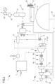
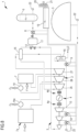
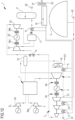
- reference number 1 overall indicates a plant for energy management according to the present invention.
- the plant 1 operates with a working fluid other than atmospheric air and comprising a working fluid which has the following chemical-physical properties: critical temperature comprised between 0°C and 200°C, density at 25°C comprised between 0.5 kg/m 3 and 10 kg/m 3 .
- a working fluid comprises carbon dioxide CO 2 .
- the working fluid comprises for example nitrogen oxide N 2 O or a mixture of CO 2 and N 2 O.
- the plant 1 is configured to actuate a closed cyclic thermodynamic transformation (CTT), first in one direction in a charge configuration/phase and then in the opposite direction in a discharge configuration/phase, in which in the charge configuration the plant 1 accumulates heat and pressure and in the discharge configuration it generates electrical and/or mechanical energy.
- CCT closed cyclic thermodynamic transformation
- the plant 1 is also configured to define/delimit a closed circuit and to actuate a closed thermodynamic cycle (TC) in said closed circuit with at least a part of the same working fluid, also while said plant 1 is in the charge configuration or in the discharge configuration.
- TC thermodynamic cycle
- the plant 1 comprises an expander defined by a turbine 2, configured to expand the working fluid, and a compressor 3 of rotary type (turbocharger), configured to compress the working fluid.
- the compressor 3 is schematically illustrated as comprising three stages.
- connection devices 4A, 4B e.g. of friction type, which allow connecting and disconnecting upon command the turbine 2 and/or the compressor 3 to/from the motor generator 4.
- the plant 1 comprises a casing 5 preferably defined by a pressure-balloon made of flexible material, for example made of PVC coated polyester fabric.
- the pressure-balloon is preferably arranged on the surface and not in subterranean caverns, and is externally in contact with the atmospheric air.
- the pressure-balloon delimits, at its interior, a volume configured to contain the working fluid at atmospheric pressure or substantially atmospheric pressure, i.e. in equilibrium of pressure with the atmosphere.
- the casing 5 can also be made as a gasometer or any other storage system for gas at low or zero over-pressure.
- the plant 1 comprises a tank 6 configured to store the working fluid in liquid or super-critical phase with a temperature close to its own critical temperature.
- the tank 6 is preferably made of metal, with an external wall of cylindrical form, as illustrated, or spherical form.
- the plant 1 comprises a combustion chamber 7 configured to actuate an oxy-combustion and to heat the working fluid therewith and heat exchangers 8, 9, 10, 11 configured to transfer heat to the working fluid or to absorb heat from the working fluid.
- Ducts defined for example by a plurality of tubes, are operationally interposed between the casing 5 and the tank 6 and connect together, directly and/or indirectly, the casing 5, the tank 6, the compressor 3, the turbine 2, the combustion chamber 7 and the heat exchangers 8, 9, 10, 11.
- the abovementioned ducts delimit a charge path which is extended from the casing 5 to the tank 6 and along which the compressor 3 and a first heat exchanger 8 are arranged in succession.
- the abovementioned ducts delimit a discharge path which is extended from the tank 6 to the casing 5 and along which the first heat exchanger 8, the combustion chamber 7, the turbine 2 and a second heat exchanger 9 are arranged in succession.
- the abovementioned ducts also delimit a closed circuit in fluid communication with the discharge path and with the charge path and consisting of the abovementioned combustion chamber 7, the abovementioned turbine 2, the abovementioned second heat exchanger 9, the abovementioned compressor 3.
- the combustion chamber 7 is operationally active in the closed circuit and along the discharge path in order to heat the working fluid by means of an oxy-combustion within the closed thermodynamic cycle and the closed cyclic thermodynamic transformation during charging.
- the combustion chamber 7 is part of a turbomachine which comprises the abovementioned turbine 2 and the turbocharger 3.
- the combustion chamber 7 is annular and is situated around a shaft which connects the turbine 2 to the compressor 3.
- passages and/or ducts are present which connect together the compressor 3, the turbine 2 and the combustion chamber 7.
- a third and a fourth heat exchanger 10, 11 are interposed between the stages of the compressor 3 in order to actuate an inter-cooled compression.
- a first section of the ducts is extended between the casing 5 and an inlet 3a of the compressor 3.
- a second section is extended between an outlet 3b of the compressor 3 and an inlet 7a of the combustion chamber 7.
- a first connector 12 is arranged, from which a third section of the ducts departs which is connected to the tank 6.
- a fourth section is extended between an outlet 7b of the combustion chamber 7 and an inlet 2a of the turbine 2.
- a fifth section is extended between an outlet 2b of the turbine 2 and a second connector 13 arranged on the first section at the inlet 3a of the compressor 3.
- a mixer 14 is situated which has an inlet for the oxygen O 2 necessary for the oxy-combustion.
- the working fluid that transits in the ducts passes through the mixer 14 and here it is mixed with the oxygen O 2 before entering into the combustion chamber 7.
- the fuel F is introduced into the mixer together with the oxygen O 2 or fuel F and oxygen O 2 are introduced, together or separately, in one or more points of the closed circuit, for example by means of respective mixers.
- the combustion chamber has an inlet for a fuel F, such as for example methane or other products containing carbon.
- the fuel comprises products containing nitrogen, such as ammonia NH 3 and/or hydrazine and/or urea.
- the fuel F and the oxygen O 2 give rise to an exothermic reaction which produces heat, carbon dioxide and other products.
- CH 4 + 2 O 2 CO 2 + 2 H 2 O + Heat.
- the heat heats the working fluid and the carbon dioxide and further substances, result of the combustion, are mixed with the working fluid (comprising or constituted by carbon dioxide) which transits in the combustion chamber 7.
- the oxy-combustion occurs with an excess of fuel or of oxygen, so that a part of the fuel or of the oxygen becomes part of the working fluid and circulates in the ducts.
- fuel F with CH 4 and production of CO 2
- a recuperator 15 is operationally active on the closed circuit to recover heat from the working fluid exiting from the turbine 2 and transfer it to the working fluid entering the combustion chamber 7.
- the recuperator 15 is situated on the second section between the outlet 3b of the compressor 3 and the first connector 12.
- the recuperator 15 is also situated on the fifth section, between the outlet 2b of the turbine 2 and the second heat exchanger 9 which is placed on said fifth section.
- a separator 16 of carbon dioxide is positioned, configured to separate carbon dioxide from other products of the oxy-combustion, such as for example water, and extracting the latter from the ducts, i.e. from the process.
- the first heat exchanger 8 and a thermal accumulator 17 are also arranged.
- the thermal accumulator 17 is positioned between the first heat exchanger 8 and the first connector 12.
- a device 18 for the extraction of non-condensable gases (NCG) of continuous or batch operating type (as a function of what will be used as fuel) is also connected to the tank 6.
- NCG non-condensable gases
- the plant 1 also comprises a water circuit comprising a tub 19 in equilibrium with the atmospheric pressure and ducts which connect the tub 19 to the first, second, third and fourth heat exchanger 8, 9, 10, 11.
- the abovementioned tub 19 is also coupled to a radiator 20 provided with one or more suckers 21 placed on a recirculation duct which, for example, cools the water during the night and heats it during the day.
- Introduction/extraction ducts 22 (schematized in figure 1 ) in fluid communication with the ducts and/or with the tank 6 and/or with the casing 5 are provided in order to allow introducing the working fluid in the plant 1 in a controlled manner.
- the same ducts 22 can also be used to extract the working fluid from the plant in a controlled manner.
- Said ducts 22 are for example connected to a system of capture and sequestration of the carbon dioxide.
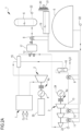
- the variant of figure 2 differs from figure 1 since the recuperator 15 is situated on the second section between the first connector 12 and the mixer 14 instead of between the outlet 3b of the compressor 3 and the first connector 12.
- the carbon dioxide separator 16 is placed on the fifth section between the second heat exchanger 9 and the second connector 13 instead of between the recuperator 15 and the second heat exchanger 9.
- the device 18 for the extraction of non-condensable gases (NCG) is provided with an expander 23 of the non-condensable gases connected to a respective generator.
- the device 18 for the extraction of non-condensable gases (NCG) can be provided with a heater and/or a cooler (in order to increase the condensation efficiency).
- the non-condensable gases NCG if not harmful for the environment, can be expelled directly into atmosphere or through an expander (with independent generator or connected to the rotary machines already present in the system, or which drives an operating machine useful or not useful for the system). Such non-condensable gases NCG can also be preheated before the expansion step in order to prevent reaching cryogenic temperatures. Alternatively, the non-condensable gases NCG can be delivered to an external system for a treatment/storage.
- the device 18 for the extraction of non-condensable gases (NCG) allows extracting components with molecular weight lower than the working fluid (such as N 2 , NO, NO 2 ), extractible from the non-condensable gas system.
- figure 2A differs from figure 1 since, as in figure 2 , the recuperator 15 is situated on the second section between the first connector 12 and the mixer 14 instead of between the outlet 3b of the compressor 3 and the first connector 12.
- the compressor 3 is connected to an electric motor 24 and the turbine 2 is mechanically connected to a motor generator 4, with a friction element 4B interposed, and to a driven/operating machine 25, e.g. a machine train for air division.
- a further variant, not illustrated, differs from figure 1 only because the recuperator 15 is situated on the second section between the first connector 12 and the mixer 14 instead of between the outlet 3b of the compressor 3 and the first connector 12.
- the plant 1 is configured to operate in a charge configuration or in a discharge configuration, i.e. to execute a process comprising an energy charge phase and an energy generation and discharge phase (Cyclic thermodynamic transformation (CTT)).
- CTT Cyclic thermodynamic transformation
- the plant 1 is also configured to actuate the closed thermodynamic cycle (TC) in the closed circuit.
- TC thermodynamic cycle
- the operation of the plant is substantially that described in the patent application WO 2020/039416 on behalf of the same Applicant, except for the fact that the heat transmitted to the working fluid during the discharge is also and mainly provided by the oxy-combustion which occurs in the combustion chamber 7.
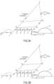
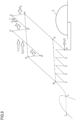
- the working fluid (CO 2 ) in gaseous form is contained in the casing 5 at atmospheric pressure or substantially atmospheric pressure and at a temperature substantially equal to the ambient temperature (point A of the diagram T-S of figure 3A ).
- the casing 5, by means of the valves, is placed in communication with the inlet 3a of the compressor 3.
- the thermal accumulator 17 is placed in fluid communication with the outlet 3b of the compressor 3.
- the motor generator 4 actuates the compressor 3 so as to compress the working fluid coming from the casing 5.
- the working fluid is compressed in the compressor 3 by means of an inter-cooled compression and is heated (from A to B of the diagram T-S of figure 3A ).
- a part of the working fluid (for example 70%) is directed towards the thermal accumulator 17 and the first heat exchanger 8 and another part (for example 30%) flows towards the mixer 14 and the combustion chamber 7.
- the thermal accumulator 17 removes heat from the compressed working fluid, cooling it (point C of the diagram T-S of figure 3A ) and accumulates the thermal energy removed from said working fluid.
- the working fluid is situated at a temperature lower than the critical temperature of said fluid and at a point on the right part of the Andrews curve or slightly outside the curve in slight overheating conditions.
- the abovementioned compression can be adiabatic, inter-cooled or isothermal.
- the working fluid passes through the first heat exchanger 8 which removes further heat from the working fluid and accumulates further thermal energy and is accumulated in the tank 6.
- the working fluid crosses the saturated vapor zone up to reaching the liquid phase (point D of the diagram T-S of figure 3A ).
- the tank 6 therefore accumulates the working fluid in liquid phase at a temperature lower than its own critical temperature Tc.
- the thermal accumulator 17 and the first heat exchanger 8 are therefore configured to operate a sub-critical transformation of the working fluid such that said working fluid is accumulated in the tank 6 in liquid phase.
- the device 18 for the extraction of non-condensable gases (NCG) provides for eliminating the NCGs from the tank 6.
- a temperature of the working fluid (CO 2 ) accumulated in the tank 6 is 24°C and a pressure of the working fluid accumulated in the tank 6 is 65 bar.
- the density of the CO 2 at 25°C and at atmospheric pressure is about 1.8 kg/m 3 .
- the density of the CO 2 in the tank 6 is about 730 kg/m 3 .
- the ratio between the density of the working fluid when it is contained in the tank 6 in the above-indicated conditions and the density of the same working fluid when it is contained in the casing 5 at atmospheric conditions is therefore about 400.
- atmospheric air is used that is stored at 65 bar and 24°C in the tank 6, its density would only be 78 kg/m 3 and the volume of the tank 6 theoretically necessary would be about ten times higher.
- the part of the working fluid (30%) that operates according to the closed thermodynamic cycle (TC) is preheated in the recuperator 15 (point E of the diagram T-S of figure 3A ) and then heated by means of the oxy-combustion in the combustion chamber 7 (point F of the diagram T-S of figure 3A ), then enters into the turbine 2 where it is expanded and is cooled (up to point G of the diagram T-S of figure 3A ).
- the turbine 2 transforms the energy of the working fluid into electrical energy/power Pw ( figures 1 and 2 ) and/or mechanical energy/power ( figure 2A ).
- the part of the working fluid is then cooled first in the recuperator 15 (up to point H of the diagram T-S of figure 3A ) and then in the second heat exchanger 9 (and reported at point A of the diagram T-S of figure 3A ).
- the separator 16 the products of the oxy-combustion like water are separated from carbon dioxide and extracted from the plant at the appropriate position along the ducts and/or from the tanks at high pressure.
- the working fluid is re-introduced into the compressor 3 in order to re-initiate the closed thermodynamic cycle (TC).
- the diagram of figure 3B illustrates a discharge configuration/phase with simultaneous closed thermodynamic cycle (TC).
- the plant 1 departs from the second state (point I of the diagram T-S of figure 3B ).
- the casing 5, by means of the valves, is placed in communication with the outlet 2b of the turbine 2.
- the thermal accumulator 17 and the first heat exchanger 8 are placed in fluid communication with the inlet 2a of the turbine 2.
- the first heat exchanger 8 transfers part of the heat, previously accumulated in the charge configuration, to the working fluid exiting from the tank 6.
- the exchanger 8 is capable, through the tub 19 of water, of transferring the heat coming from the environment, exploiting the effects of "temperature swing" between day and night. In this manner, one obtains an evaporation pressure higher than the condensation pressure, thus increasing the RTE efficiency.
- the working fluid crosses the saturated vapor zone up to reaching the vapor phase (point L of the diagram T-S of figure 3B ).
- the working fluid crosses the thermal accumulator 17 which transfers further heat, previously accumulated in the charge configuration, to the working fluid and heats it (point M of the diagram T-S of figure 3B ).
- the working fluid then crosses the recuperator 15 (point N of the diagram T-S of figure 3B ) and then it is heated (up to point O of the diagram T-S of figure 3B ) in the combustion chamber 7.
- the heated working fluid enters into the turbine 2, is expanded and is cooled (point P of the diagram T-S of figure 3B ) and determines the rotation of the turbine 2 which generates electrical and/or mechanical energy/power Pw.
- the expansion of the working fluid in the turbine 2 can be adiabatic, inter-heated or isothermal.
- the working fluid exiting from the turbine 2 is cooled in the recuperator 15 (point Q of the diagram T-S of figure 3B ) and then in the second heat exchanger 9 (point R of the diagram T-S of figure 3B ).
- a part of the working fluid (for example 70%) is directed towards the casing 5 and returns into the casing 5 at atmospheric pressure or substantially atmospheric pressure.
- Another part (for example 30%) is sent to the compressor 2 in order to execute the closed thermodynamic cycle (points R-M-N-O-P-Q-R of figure 3B or points A-B-E-F-G-HA of figure 3A ) described above.
- the additional carbon dioxide CO 2 produced by the oxy-combustion in the combustion chamber 7 becomes part of the closed cyclic thermodynamic transformation (CTT) and/or of the closed thermodynamic cycle (TC). All or part of the excess carbon dioxide CO 2 can be extracted in a controlled manner from the plant through the introduction/extraction ducts 22. The excess CO 2 can exit from the plant also at separate times due to the accumulations available to the plant. The water is separated and extracted through the separator 16. The non-condensable gases NCG are extracted through the device 18 for the extraction of non-condensable gases.
- the plant 1 allows generating electrical energy with a system that "burns" fuel without introducing CO 2 into the atmosphere but rather storing it, for example in tanks or underground, e.g. through re-injection wells, and/or rendering it available for other uses.
- the plant 1 also allows introducing, through said introduction/extraction ducts 22, carbon dioxide coming from other sources and using it as working fluid.
- the introduced carbon dioxide derives from the gasification of biomasses or from industrial processes.
- the plant/process according to the present invention can be coupled/integrated with the plants/processes that transform minerals into more precious and non-ferrous materials (e.g. aluminum or nickel alloys) by means of reductions/oxidation-reductions.
- Such processes give, as final result, a gas mixture which can be used in the plant/process, object of the invention, as fuel.
- BFG blast furnace outlet gas
- BFG blast furnace outlet gas
- Such gas is mainly composed of 5% H 2 , 20% CO, 25% CO 2 and 50% N 2 .
- LDG gas mainly composed of 60% CO, 10-15% N 2 and the rest CO 2 , which is the gas exiting from the cast iron-steel converter.
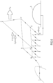
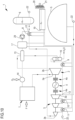
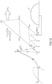
- the variant of figure 4 differs from figure 1 since the expander comprises a turbine 26 at high pressure and turbine 27 at low pressure connected in series.
- the combustion chamber 7 with the mixer 14 is operationally interposed between an outlet 26b of the turbine 26 at high pressure and an inlet 27a of the turbine 27 at low pressure.
- the recuperator 15 is situated on the second section between the first connector 12 and an inlet 26a of the turbine 26 at high pressure.
- An outlet 27b of the turbine 27 at low pressure is connected to the second connector 13.
- the turbines can be of the same or different technology (axial, radial etc.).
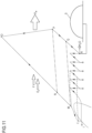
- the diagram of figure 5 illustrates the discharge configuration/phase with simultaneous closed thermodynamic cycle (TC) and differs from the diagram of figure 3B due to the presence of the expansion N-N' in the turbine 26 at high pressure.
- TC thermodynamic cycle
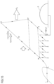
- figure 6 differs from figure 4 due to the presence of a second combustion chamber 7a (reheat) with relative mixer 14a interposed between the recuperator 15 and the inlet 26a of the turbine 26 at high pressure.
- the diagram of figure 7 illustrates the discharge configuration/phase with simultaneous closed thermodynamic cycle (TC) and differs from the diagram of figure 3B due to the presence of the double oxy-combustion N-O' and P'-O and of the double expansion O'-P' and O-P in the turbine 26, 27 at high and low pressure.
- the variant of figure 8 is a combination of those of figures 4 and 6 with a turbine 26 at high pressure, a turbine 28 at medium pressure and a turbine 27 at low pressure in which the combustion chambers 7, 7a with the relative mixers 14, 14a are placed between the turbine 26 at high pressure and the turbine 28 at medium pressure and between the turbine 28 at medium pressure and the turbine 27 at low pressure.
- the diagram of figure 9 illustrates the discharge configuration/phase with simultaneous closed thermodynamic cycle (TC) and has the expansion N-N' in the turbine 26 at high pressure, the double oxy-combustion N'-O' and P'-O and the double expansion O'-P' and O-P in the turbine 28, 27 at medium and low pressure.
- the variant of figure 10 differs from figure 1 since, as in figure 2 , the recuperator 15 is situated on the second section between the first connector 12 and the mixer 14 instead of between the outlet 3b of the compressor 3 and the first connector 12.
- a pump 29 is placed upstream of the mixer 14 and of the combustion chamber 7 in order to increase an inlet pressure in the turbine 2.
- the first connector 12, the first heat exchanger 8 and the thermal accumulator 17 have an arrangement different from that of figure 1 .
- the first heat exchanger 8 is placed between the outlet 3b of the compressor 3 and the first connector 12, the thermal accumulator 17 is placed between the first connector 12 and the mixer 14, the pump 29 is placed between the first connector 12 and the thermal accumulator 17. It follows that the first heat exchanger 8 works in accumulation and in the closed cycle and does not discharge while the thermal accumulator 17 and the pump 29 work in discharge and in the closed cycle but do not accumulate.
- the diagram of figure 11 illustrates the discharge configuration/phase with simultaneous closed thermodynamic cycle (TC) and differs from the diagram of figure 3B due to the fact that the pump 29 increases the pressure (I-L') before the passage into the thermal accumulator 17 (L'-M).
- the working fluid is not made to evaporate once again since the working fluid is brought into super-critical condition with the pump. It is also possible to preheat the working fluid with heat accumulated in a thermal accumulator, using the heat extracted from the compression inter-coolings.
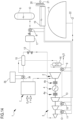
- figure 12 differs from figure 1 since, as in figure 2 , the recuperator 15 is situated on the second section between the first connector 12 and the mixer 14 instead of between the outlet 3b of the compressor 3 and the first connector 12.
- the oxygen O 2 is introduced directly into the combustion chamber 7 (no mixer is present) through a dedicated compressor 30 and also the fuel is introduced into the combustion chamber 7 through an auxiliary compressor 31.
- the variant of figure 12 also comprises an additional machine comprising an auxiliary compressor 31 and an auxiliary turbine 33 mechanically connected to an auxiliary motor generator 32 by means of connection devices 34A, 34B of friction type.
- Such additional machine is connected to the ducts between the first connector 12 and the tank 6 and has the function of working the closed thermodynamic cycle between a maximum pressure and a minimum pressure in which the maximum pressure is lower than a condensation pressure.
- the condensation pressure is reached, due to the auxiliary compressor 31, by the part of working fluid that is accumulated in the tank 6 while the part that circulates in the closed circuit reaches a lower maximum pressure.
- the closed thermodynamic cycle can work between a maximum pressure (e.g. between 5 bar and 45 bar) lower than a maximum pressure of the process, i.e.
- the process comprises a recuperative cycle at medium-low temperature which can work independently from the second transformation, which increases the pressure up to reaching the conditions which allow the storage in liquid phase of the working fluid in the tank 6.
- the auxiliary compressor 31 is arranged along the charge path between the first connector 12 and the thermal accumulator 17.
- the working fluid coming from the first connector 12 enters into the auxiliary compressor 31, is compressed and directed towards the thermal accumulator 17 and then through the first heat exchanger 8.
- the auxiliary turbine 33 is arranged along the discharge path between the thermal accumulator 17 and the first connector 12.
- the diagram of figure 13 illustrates the phases of charge and discharge with simultaneous closed thermodynamic cycle (TC).
- TC thermodynamic cycle
- the auxiliary compressor 31 might not operate and the recuperator 15 could exchange much heat if the temperature of the auxiliary turbine 33 is lower than the delivery temperature of the compressor 3.
- figure 14 differs from figure 1 since, as in figure 2 , the recuperator 15 is situated on the second section between the first connector 12 and the mixer 14 instead of between the outlet 3b of the compressor 3 and the first connector 12.
- the oxygen O 2 is introduced directly into the combustion chamber 7 (no mixer is present) as the fuel.
- the oxygen is introduced into the combustion chamber 7 while the fuel is mixed upstream of the combustion chamber.
- the variant of figure 14 also comprises a further heat exchanger 34 operationally associated with an additional external heat source 35, in order to receive heat from said additional external heat source 35.
- the further heat exchanger 34 is operationally placed on the discharge path between the recuperator 15 and the combustion chamber 7. The heat coming from outside is used to increase the temperature of the working fluid entering the combustion chamber 7 and increase the efficiency.
- the additional external heat source 35 is a methanation plant dedicated to the conversion of hydrogen into Synthetic Natural Gas through the exothermic reaction H +CO 2 - > CH 4 + H 2 O + heat.
- the diagram of figure 15 illustrates the discharge configuration/phase with simultaneous closed thermodynamic cycle (TC) and differs from the diagram of figure 3B due to the fact that after the heating in the recuperator 15 (M-N) and before the oxy-combustion (N'-O), the heating in the further heat exchanger 34 (N'-N) is presence.
- the yield of the plant/process according to the invention can vary due to the use of energy stored in the accumulations (in the form of heat with TES and in the form of potential energy in pressure tanks).
- the plant/process also allows extracting heat at low temperature, typically lower than 100°C, in order to supply external users or cooling circuits of the inter-coolers of the compressor or of the post-cooler of the turbine, i.e. the second heat exchanger 9.
Landscapes
- Engineering & Computer Science (AREA)
- Chemical & Material Sciences (AREA)
- Combustion & Propulsion (AREA)
- Mechanical Engineering (AREA)
- General Engineering & Computer Science (AREA)
- Engine Equipment That Uses Special Cycles (AREA)
- Management, Administration, Business Operations System, And Electronic Commerce (AREA)
Claims (17)
- Anlage zum Energiemanagement, umfassend:ein von atmosphärischer Luft verschiedenes Arbeitsfluid;wenigstens ein Gehäuse (5), welches dazu eingerichtet ist, das Arbeitsfluid in gasförmiger Phase und im Druckgleichgewicht mit der Atmosphäre zu speichern;wenigstens einen Behälter (6), welcher dazu eingerichtet ist, das Arbeitsfluid mit einer seiner eigenen kritischen Temperatur nahen Temperatur in flüssiger oder überkritischer Phase zu speichern;Kanäle, welche betriebsmäßig zwischen dem Gehäuse (5) und dem Behälter (6) eingefügt sind und das Gehäuse (5) direkt und/oder indirekt mit dem Behälter (6) verbinden; wobei die Kanäle begrenzen:wenigstens einen Ladepfad, welcher sich von dem Gehäuse (5) zu dem Behälter (6) erstreckt,wenigstens einen Entladepfad, welcher sich von dem Behälter (6) zu dem Gehäuse (5) erstreckt, undwenigstens einen geschlossenen Kreislauf, welcher in Fluidkommunikation mit dem Entladepfad und mit dem Ladepfad ist;wenigstens eine Expansionseinrichtung (2), welche entlang der Kanäle angeordnet ist und dazu eingerichtet ist, das Arbeitsfluid zu expandieren;wenigstens eine Kompressionseinrichtung (3), welche entlang der Kanäle angeordnet ist und dazu eingerichtet ist, das Arbeitsfluid zu komprimieren;Wärmetauscher (8, 9, 10, 11), welche entlang der Kanäle angeordnet sind und dazu eingerichtet sind, Wärme auf das Arbeitsfluid zu übertragen oder Wärme aus dem Arbeitsfluid zu absorbieren;wobei die Anlage (1) dazu eingerichtet ist, zuerst in einer Richtung in einer Ladekonfiguration und dann in der entgegengesetzten Richtung in einer Entladekonfiguration zwischen dem Gehäuse (5) und dem Behälter (6) eine geschlossene zyklische thermodynamische Umwandlung (CTT) mit dem Arbeitsfluid auszulösen;wobei die Anlage (1) ebenfalls dazu eingerichtet ist, wenigstens einen geschlossenen thermodynamischen Zyklus (TC) in dem geschlossenen Kreislauf mit dem Arbeitsfluid auszulösen, optional während sich die Anlage (1) in der Lade- oder Entladekonfiguration befindet;dadurch gekennzeichnet, dass die Anlage wenigstens eine Brennkammer (7) umfasst, welche entlang der Kanäle angeordnet ist und dazu eingerichtet ist, eine Oxy-Verbrennung auszulösen und das Arbeitsfluid damit zu erwärmen;und dass die Brennkammer (7) wenigstens in dem geschlossenen Kreislauf betriebsmäßig wirksam ist, um das Arbeitsfluid während eines Ladens durch eine Oxy-Verbrennung innerhalb des geschlossenen thermodynamischen Zyklus (TC) und/oder der geschlossenen zyklischen thermodynamischen Umwandlung (CTT) zu erwärmen.
- Anlage nach Anspruch 1, wobei die Brennkammer (7) dazu eingerichtet ist, direkt oder indirekt einen Brennstoff (F) und Sauerstoff (O2) zu empfangen und durch eine Oxy-Verbrennung erzeugte Produkte in die Kanäle einzuführen.
- Anlage nach Anspruch 1 oder 2, umfassend eine Mischeinrichtung (14), welche stromaufwärts der Brennkammer (7) an den Kanälen platziert ist, wobei die Mischeinrichtung (14) einen Einlass für Sauerstoff (O2) und/oder Brennstoff (F) aufweist und wobei das Arbeitsfluid durch die Mischeinrichtung (14) strömt; wobei die Mischeinrichtung (14) dazu eingerichtet ist, Sauerstoff (O2) und/oder Brennstoff (F) und das Arbeitsfluid zu mischen, bevor es in die Brennkammer (7) eindringt.
- Anlage nach den Ansprüchen 1 bis 3, umfassend einen Separator (16) wenigstens eines der durch eine Oxy-Verbrennung erzeugten Produkte, welcher stromabwärts eines Auslasses der Expansionseinrichtung (2) platziert ist und dazu eingerichtet ist, wenigstens eines der durch die Oxy-Verbrennung erzeugten Produkte von anderen Produkten der Oxy-Verbrennung zu separieren und die anderen Produkte aus den Kanälen zu extrahieren.
- Anlage nach einem der Ansprüche 1 bis 4, umfassend wenigstens einen Extraktionskanal (22), welcher in Fluidkommunikation mit den Kanälen und/oder dem Behälter (6) und/oder dem Gehäuse (5) ist, um zu ermöglichen, dass das Arbeitsfluid in einer gesteuerten/geregelten Weise aus der Anlage (1) extrahiert wird; optional wobei der Extraktionskanal (22) mit einem System für das Einfangen und die Sequestrierung wenigstens eines der durch die Oxy-Verbrennung erzeugten Produkte verbunden ist; und/oder umfassend wenigstens einen Einlasskanal (22), welcher mit den Kanälen und/oder dem Behälter (6) und/oder dem Gehäuse (5) in Fluidverbindung ist, um zu erlauben, dass das Arbeitsfluid in einer gesteuerten/geregelten Weise in die Anlage (1) eingeführt wird.
- Anlage nach einem der Ansprüche 1 bis 5, umfassend einen Rekuperator (15), welcher an dem geschlossenen Kreislauf betriebsmäßig wirksam ist, um Wärme aus dem Arbeitsfluid zurückzugewinnen, welches aus der Expansionseinrichtung (2) herauskommt, und sie auf das Arbeitsfluid zu übertragen, welches in die Brennkammer (7) eindringt.
- Anlage nach einem der Ansprüche 1 bis 6, wobei die Wärmetauscher (8, 9, 10, 11, 17) umfassen:einen ersten Wärmetauscher (8), welcher auf dem Ladepfad zwischen einem Auslass der Expansionseinrichtung (2) und dem Behälter (6) platziert ist und/oder auf dem Entladepfad zwischen dem Behälter (6) und der Brennkammer (7) platziert ist; wobei der erste Wärmetauscher (8) dazu eingerichtet ist, in der Ladekonfiguration Wärme aus dem Arbeitsfluid zu absorbieren und/oder in der Entladekonfiguration Wärme auf das Arbeitsfluid zu übertragen;einen zweiten Wärmetauscher (9), welcher auf dem Entladepfad zwischen einem Auslass (2b) der Expansionseinrichtung (2) und dem Gehäuse (5) platziert ist und/oder in dem geschlossenen Kreislauf zwischen dem Auslass (2b) der Expansionseinrichtung (2) und einem Einlass (3a) der Kompressionseinrichtung (3) platziert ist; wobei der zweite Wärmetauscher (9) dazu eingerichtet ist, in der Entladekonfiguration Wärme aus dem Arbeitsfluid zu absorbieren und/oder in dem geschlossenen thermodynamischen Zyklus (TC) Wärme aus dem Arbeitsfluid zu absorbieren.
- Anlage nach einem der Ansprüche 1 bis 7, wobei die Wärmetauscher (8, 9, 10, 11, 17) einen thermischen Akkumulator (17) umfassen, welcher auf dem Ladepfad zwischen einem Auslass (2b) der Expansionseinrichtung (2) und dem Behälter (6) platziert ist und/oder auf dem Entladepfad zwischen dem Behälter (9) und der Brennkammer (7) platziert ist und/oder in dem geschlossenen Kreislauf platziert ist; wobei der thermische Akkumulator (17) dazu eingerichtet ist, in der Ladekonfiguration Wärme aus dem Arbeitsfluid zu absorbieren und thermische Energie zu speichern und/oder in der Entladekonfiguration Wärme auf das Arbeitsfluid zu übertragen.
- Anlage nach einem der Ansprüche 1 bis 8, umfassend einen weiteren Wärmetauscher (34), welcher betriebsmäßig mit einer zusätzlichen Wärmequelle (35) kombiniert ist, um Wärme von dieser zusätzlichen Wärmequelle (35) zu empfangen, und welcher betriebsmäßig auf dem Entladepfad und in dem geschlossenen Kreislauf und stromaufwärts der Brennkammer (7) platziert ist.
- Anlage nach einem der Ansprüche 1 bis 9, umfassend wenigstens eine Pumpe (29), welche dazu eingerichtet ist, einen Eingangsdruck in die Expansionseinrichtung (2) zu erhöhen.
- Anlage nach einem der Ansprüche 1 bis 10, wobei die wenigstens eine Expansionseinrichtung (2) eine Mehrzahl von Expansionseinrichtungen (26, 27, 28) umfasst, welche in Reihe angeordnet sind, wobei die wenigstens eine Brennkammer (7, 7a) stromaufwärts der Expansionseinrichtungen (26, 27, 28) und/oder zwischen den Expansionseinrichtungen (26, 27, 28) platziert ist.
- Anlage nach einem der Ansprüche 1 bis 11, wobei die durch die Oxy-Verbrennung erzeugten Produkte CO2 und/oder N2O umfassen.
- Verfahren zum Energiemanagement, umfassend:Auslösen einer geschlossenen zyklischen thermodynamischen Umwandlung (CTT) zuerst in einer Richtung in einer Ladekonfiguration/-phase und dann in der entgegengesetzten Richtung in einer Entladekonfiguration/-phase zwischen einem Gehäuse (5) für das Speichern eines von atmosphärischer Luft verschiedenen Arbeitsfluids in gasförmiger Phase und im Druckgleichgewicht mit der Atmosphäre und einem Behälter (6) für das Speichern des Arbeitsfluids mit einer seiner eigenen kritischen Temperatur nahen Temperatur in flüssiger oder überkritischer Phase;wobei das Verfahren in der Ladephase Wärme und potentielle Energie in der Form von Druck akkumuliert und es in der Entladephase Energie erzeugt;Auslösen, mit wenigstens einem Teil des Arbeitsfluids, wenigstens eines geschlossenen thermodynamischen Zyklus (TC), optional zu der gleichen Zeit wie die Ladephase oder die Entladephase;dadurch gekennzeichnet, dass das Verfahren umfasst: Erwärmen des Arbeitsfluids durch wenigstens eine Oxy-Verbrennung innerhalb des geschlossenen thermodynamischen Zyklus (TC).
- Verfahren nach Anspruch 13, umfassend: Einführen von Brennstoff (F) und Sauerstoff (O2) direkt oder indirekt in eine Brennkammer (7), in welche das Arbeitsfluid strömt; wobei wenigstens eines der durch die Oxy-Verbrennung erzeugten Produkte ein Teil der geschlossenen zyklischen thermodynamischen Umwandlung (CTT) und/oder des geschlossenen thermodynamischen Zyklus (TC) wird.
- Verfahren nach Anspruch 13 oder 14, umfassend: Extrahieren, in einer gesteuerten/geregelten Weise, des wenigstens einen der durch die Oxy-Verbrennung erzeugten Produkte aus der geschlossenen zyklischen thermodynamischen Umwandlung (CTT) und/oder aus dem geschlossenen thermodynamischen Zyklus (TC), um es zu speichern oder an einen Nutzer zu senden.
- Verfahren nach einem der Ansprüche 13 bis 15, umfassend: Separieren wenigstens eines der durch die Oxy-Verbrennung erzeugten Produkte von anderen Produkten der Oxy-Verbrennung und Extrahieren der anderen Produkte aus dem Verfahren.
- Verfahren nach einem der Ansprüche 13 bis 16, wobei die durch die Oxy-Verbrennung erzeugten Produkte CO2 und/oder N2O umfassen.
Applications Claiming Priority (2)
| Application Number | Priority Date | Filing Date | Title |
|---|---|---|---|
| IT102020000014566A IT202000014566A1 (it) | 2020-06-18 | 2020-06-18 | Impianto e processo per la gestione di energia |
| PCT/IB2021/055024 WO2021255578A1 (en) | 2020-06-18 | 2021-06-08 | Plant and process for energy management |
Publications (3)
| Publication Number | Publication Date |
|---|---|
| EP4168656A1 EP4168656A1 (de) | 2023-04-26 |
| EP4168656B1 true EP4168656B1 (de) | 2024-11-27 |
| EP4168656C0 EP4168656C0 (de) | 2024-11-27 |
Family
ID=72473689
Family Applications (1)
| Application Number | Title | Priority Date | Filing Date |
|---|---|---|---|
| EP21737493.3A Active EP4168656B1 (de) | 2020-06-18 | 2021-06-08 | Anlage und verfahren zur energieverwaltung |
Country Status (7)
| Country | Link |
|---|---|
| US (1) | US11873739B2 (de) |
| EP (1) | EP4168656B1 (de) |
| JP (1) | JP7741103B2 (de) |
| AU (1) | AU2021291793B2 (de) |
| CA (1) | CA3184191A1 (de) |
| IT (1) | IT202000014566A1 (de) |
| WO (1) | WO2021255578A1 (de) |
Families Citing this family (6)
| Publication number | Priority date | Publication date | Assignee | Title |
|---|---|---|---|---|
| PL245891B1 (pl) * | 2021-03-15 | 2024-10-28 | Energoprojekt Spolka Akcyjna | System izobarycznych zbiorników na dwutlenek węgla dla systemów magazynowania energii |
| IT202200013873A1 (it) * | 2022-06-30 | 2023-12-30 | Saipem Spa | Metodo di accumulo e produzione di energia associato a oxy-combustion senza emissioni di gas ad effetto serra |
| IT202200016569A1 (it) | 2022-08-03 | 2024-02-03 | Energy Dome S P A | Apparato di accumulo di energia termica ed impianto per la trasformazione e lo stoccaggio di energia |
| US12160102B1 (en) | 2022-10-06 | 2024-12-03 | Timothy Dean Watson | Energy storage system |
| IT202200022011A1 (it) | 2022-10-25 | 2023-01-25 | Energy Dome S P A | Dispositivo ed apparato per accumulare e rilasciare energia termica e impianto per la trasformazione e lo stoccaggio di energia |
| IT202300006336A1 (it) * | 2023-03-31 | 2023-07-01 | Energy Dome S P A | Impianto per la trasformazione e lo stoccaggio di energia |
Family Cites Families (8)
| Publication number | Priority date | Publication date | Assignee | Title |
|---|---|---|---|---|
| US8596075B2 (en) | 2009-02-26 | 2013-12-03 | Palmer Labs, Llc | System and method for high efficiency power generation using a carbon dioxide circulating working fluid |
| GB2484080A (en) * | 2010-09-28 | 2012-04-04 | Univ Cranfield | Power generation using a pressurised carbon dioxide flow |
| US20130333385A1 (en) * | 2011-05-24 | 2013-12-19 | Kelly Herbst | Supercritical Fluids, Systems and Methods for Use |
| WO2014052927A1 (en) | 2012-09-27 | 2014-04-03 | Gigawatt Day Storage Systems, Inc. | Systems and methods for energy storage and retrieval |
| US10458284B2 (en) * | 2016-12-28 | 2019-10-29 | Malta Inc. | Variable pressure inventory control of closed cycle system with a high pressure tank and an intermediate pressure tank |
| US10082104B2 (en) * | 2016-12-30 | 2018-09-25 | X Development Llc | Atmospheric storage and transfer of thermal energy |
| IT201700015175A1 (it) * | 2017-02-10 | 2018-08-10 | Spada S R L | Motore primo a combustione interna a ciclo semi-chiuso e processo termodinamico semi-chiuso per la produzione di potenza |
| IT201900002385A1 (it) | 2019-02-19 | 2020-08-19 | Energy Dome S P A | Impianto e processo per l’accumulo di energia |
-
2020
- 2020-06-18 IT IT102020000014566A patent/IT202000014566A1/it unknown
-
2021
- 2021-06-08 WO PCT/IB2021/055024 patent/WO2021255578A1/en not_active Ceased
- 2021-06-08 JP JP2022569539A patent/JP7741103B2/ja active Active
- 2021-06-08 AU AU2021291793A patent/AU2021291793B2/en active Active
- 2021-06-08 EP EP21737493.3A patent/EP4168656B1/de active Active
- 2021-06-08 CA CA3184191A patent/CA3184191A1/en active Pending
- 2021-06-08 US US18/001,951 patent/US11873739B2/en active Active
Also Published As
| Publication number | Publication date |
|---|---|
| CA3184191A1 (en) | 2021-12-23 |
| AU2021291793A1 (en) | 2022-12-08 |
| EP4168656A1 (de) | 2023-04-26 |
| IT202000014566A1 (it) | 2021-12-18 |
| EP4168656C0 (de) | 2024-11-27 |
| JP7741103B2 (ja) | 2025-09-17 |
| US20230220788A1 (en) | 2023-07-13 |
| WO2021255578A1 (en) | 2021-12-23 |
| JP2023530825A (ja) | 2023-07-20 |
| AU2021291793B2 (en) | 2025-06-12 |
| US11873739B2 (en) | 2024-01-16 |
Similar Documents
| Publication | Publication Date | Title |
|---|---|---|
| EP4168656B1 (de) | Anlage und verfahren zur energieverwaltung | |
| US11905857B2 (en) | Plant and process for energy generation and storage | |
| KR102738623B1 (ko) | 에너지 저장 플랜트 및 공정 | |
| EP3224458B1 (de) | Elektrothermisches energiespeichersystem und zugehöriges verfahren davon | |
| EP0277777B1 (de) | Kraftanlage mit C02 als Arbeitsfluidum | |
| US20170058768A1 (en) | Method And Device For Storing And Recovering Energy | |
| US9388712B2 (en) | Methods and apparatus for an oxy-fuel based power cycle | |
| McClung et al. | Comparison of supercritical carbon dioxide cycles for oxy-combustion | |
| CN101529055A (zh) | 热力发动机系统 | |
| JP7554920B2 (ja) | エネルギー貯蔵のためのプラント及びプロセス | |
| US12180889B2 (en) | System and method for storing and recovering energy using compressed-gas with recovery liquid | |
| KR20220051911A (ko) | 순산소연소 가스터빈 이산화탄소 포집장치 및 운전방법 | |
| US12486790B2 (en) | Intermediate pressure supercritical CO2 power cycle | |
| OA21339A (en) | Plant and process for energy generation and storage. | |
| EA046333B1 (ru) | Установка и способ генерирования и хранения энергии |
Legal Events
| Date | Code | Title | Description |
|---|---|---|---|
| STAA | Information on the status of an ep patent application or granted ep patent |
Free format text: STATUS: UNKNOWN |
|
| STAA | Information on the status of an ep patent application or granted ep patent |
Free format text: STATUS: THE INTERNATIONAL PUBLICATION HAS BEEN MADE |
|
| PUAI | Public reference made under article 153(3) epc to a published international application that has entered the european phase |
Free format text: ORIGINAL CODE: 0009012 |
|
| STAA | Information on the status of an ep patent application or granted ep patent |
Free format text: STATUS: REQUEST FOR EXAMINATION WAS MADE |
|
| 17P | Request for examination filed |
Effective date: 20221230 |
|
| AK | Designated contracting states |
Kind code of ref document: A1 Designated state(s): AL AT BE BG CH CY CZ DE DK EE ES FI FR GB GR HR HU IE IS IT LI LT LU LV MC MK MT NL NO PL PT RO RS SE SI SK SM TR |
|
| P01 | Opt-out of the competence of the unified patent court (upc) registered |
Effective date: 20230505 |
|
| DAV | Request for validation of the european patent (deleted) | ||
| DAX | Request for extension of the european patent (deleted) | ||
| GRAP | Despatch of communication of intention to grant a patent |
Free format text: ORIGINAL CODE: EPIDOSNIGR1 |
|
| STAA | Information on the status of an ep patent application or granted ep patent |
Free format text: STATUS: GRANT OF PATENT IS INTENDED |
|
| INTG | Intention to grant announced |
Effective date: 20240711 |
|
| GRAS | Grant fee paid |
Free format text: ORIGINAL CODE: EPIDOSNIGR3 |
|
| GRAA | (expected) grant |
Free format text: ORIGINAL CODE: 0009210 |
|
| STAA | Information on the status of an ep patent application or granted ep patent |
Free format text: STATUS: THE PATENT HAS BEEN GRANTED |
|
| AK | Designated contracting states |
Kind code of ref document: B1 Designated state(s): AL AT BE BG CH CY CZ DE DK EE ES FI FR GB GR HR HU IE IS IT LI LT LU LV MC MK MT NL NO PL PT RO RS SE SI SK SM TR |
|
| REG | Reference to a national code |
Ref country code: GB Ref legal event code: FG4D |
|
| REG | Reference to a national code |
Ref country code: CH Ref legal event code: EP |
|
| REG | Reference to a national code |
Ref country code: IE Ref legal event code: FG4D |
|
| REG | Reference to a national code |
Ref country code: DE Ref legal event code: R096 Ref document number: 602021022469 Country of ref document: DE |
|
| U01 | Request for unitary effect filed |
Effective date: 20241217 |
|
| P04 | Withdrawal of opt-out of the competence of the unified patent court (upc) registered |
Free format text: CASE NUMBER: APP_649/2025 Effective date: 20250108 |
|
| U07 | Unitary effect registered |
Designated state(s): AT BE BG DE DK EE FI FR IT LT LU LV MT NL PT RO SE SI Effective date: 20250110 |
|
| PG25 | Lapsed in a contracting state [announced via postgrant information from national office to epo] |
Ref country code: IS Free format text: LAPSE BECAUSE OF FAILURE TO SUBMIT A TRANSLATION OF THE DESCRIPTION OR TO PAY THE FEE WITHIN THE PRESCRIBED TIME-LIMIT Effective date: 20250327 Ref country code: HR Free format text: LAPSE BECAUSE OF FAILURE TO SUBMIT A TRANSLATION OF THE DESCRIPTION OR TO PAY THE FEE WITHIN THE PRESCRIBED TIME-LIMIT Effective date: 20241127 |
|
| PG25 | Lapsed in a contracting state [announced via postgrant information from national office to epo] |
Ref country code: ES Free format text: LAPSE BECAUSE OF FAILURE TO SUBMIT A TRANSLATION OF THE DESCRIPTION OR TO PAY THE FEE WITHIN THE PRESCRIBED TIME-LIMIT Effective date: 20241127 |
|
| PG25 | Lapsed in a contracting state [announced via postgrant information from national office to epo] |
Ref country code: NO Free format text: LAPSE BECAUSE OF FAILURE TO SUBMIT A TRANSLATION OF THE DESCRIPTION OR TO PAY THE FEE WITHIN THE PRESCRIBED TIME-LIMIT Effective date: 20250227 |
|
| PG25 | Lapsed in a contracting state [announced via postgrant information from national office to epo] |
Ref country code: GR Free format text: LAPSE BECAUSE OF FAILURE TO SUBMIT A TRANSLATION OF THE DESCRIPTION OR TO PAY THE FEE WITHIN THE PRESCRIBED TIME-LIMIT Effective date: 20250228 |
|
| PG25 | Lapsed in a contracting state [announced via postgrant information from national office to epo] |
Ref country code: PL Free format text: LAPSE BECAUSE OF FAILURE TO SUBMIT A TRANSLATION OF THE DESCRIPTION OR TO PAY THE FEE WITHIN THE PRESCRIBED TIME-LIMIT Effective date: 20241127 |
|
| PG25 | Lapsed in a contracting state [announced via postgrant information from national office to epo] |
Ref country code: RS Free format text: LAPSE BECAUSE OF FAILURE TO SUBMIT A TRANSLATION OF THE DESCRIPTION OR TO PAY THE FEE WITHIN THE PRESCRIBED TIME-LIMIT Effective date: 20250227 |
|
| PG25 | Lapsed in a contracting state [announced via postgrant information from national office to epo] |
Ref country code: SM Free format text: LAPSE BECAUSE OF FAILURE TO SUBMIT A TRANSLATION OF THE DESCRIPTION OR TO PAY THE FEE WITHIN THE PRESCRIBED TIME-LIMIT Effective date: 20241127 |
|
| PG25 | Lapsed in a contracting state [announced via postgrant information from national office to epo] |
Ref country code: SK Free format text: LAPSE BECAUSE OF FAILURE TO SUBMIT A TRANSLATION OF THE DESCRIPTION OR TO PAY THE FEE WITHIN THE PRESCRIBED TIME-LIMIT Effective date: 20241127 |
|
| PG25 | Lapsed in a contracting state [announced via postgrant information from national office to epo] |
Ref country code: CZ Free format text: LAPSE BECAUSE OF FAILURE TO SUBMIT A TRANSLATION OF THE DESCRIPTION OR TO PAY THE FEE WITHIN THE PRESCRIBED TIME-LIMIT Effective date: 20241127 |
|
| U20 | Renewal fee for the european patent with unitary effect paid |
Year of fee payment: 5 Effective date: 20250624 |
|
| PLBE | No opposition filed within time limit |
Free format text: ORIGINAL CODE: 0009261 |
|
| STAA | Information on the status of an ep patent application or granted ep patent |
Free format text: STATUS: NO OPPOSITION FILED WITHIN TIME LIMIT |
|
| 26N | No opposition filed |
Effective date: 20250828 |