EP4168236B1 - Method of forming a container having a hanging implement - Google Patents
Method of forming a container having a hanging implement Download PDFInfo
- Publication number
- EP4168236B1 EP4168236B1 EP20743791.4A EP20743791A EP4168236B1 EP 4168236 B1 EP4168236 B1 EP 4168236B1 EP 20743791 A EP20743791 A EP 20743791A EP 4168236 B1 EP4168236 B1 EP 4168236B1
- Authority
- EP
- European Patent Office
- Prior art keywords
- tail
- container
- preform
- blow molding
- shaped
- Prior art date
- Legal status (The legal status is an assumption and is not a legal conclusion. Google has not performed a legal analysis and makes no representation as to the accuracy of the status listed.)
- Active
Links
Images




Classifications
-
- B—PERFORMING OPERATIONS; TRANSPORTING
- B29—WORKING OF PLASTICS; WORKING OF SUBSTANCES IN A PLASTIC STATE IN GENERAL
- B29C—SHAPING OR JOINING OF PLASTICS; SHAPING OF MATERIAL IN A PLASTIC STATE, NOT OTHERWISE PROVIDED FOR; AFTER-TREATMENT OF THE SHAPED PRODUCTS, e.g. REPAIRING
- B29C49/00—Blow-moulding, i.e. blowing a preform or parison to a desired shape within a mould; Apparatus therefor
- B29C49/42—Component parts, details or accessories; Auxiliary operations
- B29C49/4273—Auxiliary operations after the blow-moulding operation not otherwise provided for
-
- B—PERFORMING OPERATIONS; TRANSPORTING
- B29—WORKING OF PLASTICS; WORKING OF SUBSTANCES IN A PLASTIC STATE IN GENERAL
- B29C—SHAPING OR JOINING OF PLASTICS; SHAPING OF MATERIAL IN A PLASTIC STATE, NOT OTHERWISE PROVIDED FOR; AFTER-TREATMENT OF THE SHAPED PRODUCTS, e.g. REPAIRING
- B29C49/00—Blow-moulding, i.e. blowing a preform or parison to a desired shape within a mould; Apparatus therefor
- B29C49/02—Combined blow-moulding and manufacture of the preform or the parison
- B29C49/04—Extrusion blow-moulding
- B29C49/04102—Extrusion blow-moulding extruding the material continuously
-
- B—PERFORMING OPERATIONS; TRANSPORTING
- B29—WORKING OF PLASTICS; WORKING OF SUBSTANCES IN A PLASTIC STATE IN GENERAL
- B29C—SHAPING OR JOINING OF PLASTICS; SHAPING OF MATERIAL IN A PLASTIC STATE, NOT OTHERWISE PROVIDED FOR; AFTER-TREATMENT OF THE SHAPED PRODUCTS, e.g. REPAIRING
- B29C49/00—Blow-moulding, i.e. blowing a preform or parison to a desired shape within a mould; Apparatus therefor
- B29C49/02—Combined blow-moulding and manufacture of the preform or the parison
- B29C49/06—Injection blow-moulding
-
- B—PERFORMING OPERATIONS; TRANSPORTING
- B29—WORKING OF PLASTICS; WORKING OF SUBSTANCES IN A PLASTIC STATE IN GENERAL
- B29C—SHAPING OR JOINING OF PLASTICS; SHAPING OF MATERIAL IN A PLASTIC STATE, NOT OTHERWISE PROVIDED FOR; AFTER-TREATMENT OF THE SHAPED PRODUCTS, e.g. REPAIRING
- B29C49/00—Blow-moulding, i.e. blowing a preform or parison to a desired shape within a mould; Apparatus therefor
- B29C49/08—Biaxial stretching during blow-moulding
- B29C49/086—Biaxial stretching during blow-moulding mono-axial stretching, e.g. either length or width
-
- B—PERFORMING OPERATIONS; TRANSPORTING
- B29—WORKING OF PLASTICS; WORKING OF SUBSTANCES IN A PLASTIC STATE IN GENERAL
- B29C—SHAPING OR JOINING OF PLASTICS; SHAPING OF MATERIAL IN A PLASTIC STATE, NOT OTHERWISE PROVIDED FOR; AFTER-TREATMENT OF THE SHAPED PRODUCTS, e.g. REPAIRING
- B29C49/00—Blow-moulding, i.e. blowing a preform or parison to a desired shape within a mould; Apparatus therefor
- B29C49/08—Biaxial stretching during blow-moulding
- B29C49/10—Biaxial stretching during blow-moulding using mechanical means for prestretching
- B29C49/12—Stretching rods
-
- B—PERFORMING OPERATIONS; TRANSPORTING
- B29—WORKING OF PLASTICS; WORKING OF SUBSTANCES IN A PLASTIC STATE IN GENERAL
- B29C—SHAPING OR JOINING OF PLASTICS; SHAPING OF MATERIAL IN A PLASTIC STATE, NOT OTHERWISE PROVIDED FOR; AFTER-TREATMENT OF THE SHAPED PRODUCTS, e.g. REPAIRING
- B29C49/00—Blow-moulding, i.e. blowing a preform or parison to a desired shape within a mould; Apparatus therefor
- B29C49/42—Component parts, details or accessories; Auxiliary operations
- B29C49/4268—Auxiliary operations during the blow-moulding operation
-
- B—PERFORMING OPERATIONS; TRANSPORTING
- B29—WORKING OF PLASTICS; WORKING OF SUBSTANCES IN A PLASTIC STATE IN GENERAL
- B29C—SHAPING OR JOINING OF PLASTICS; SHAPING OF MATERIAL IN A PLASTIC STATE, NOT OTHERWISE PROVIDED FOR; AFTER-TREATMENT OF THE SHAPED PRODUCTS, e.g. REPAIRING
- B29C49/00—Blow-moulding, i.e. blowing a preform or parison to a desired shape within a mould; Apparatus therefor
- B29C49/42—Component parts, details or accessories; Auxiliary operations
- B29C49/4273—Auxiliary operations after the blow-moulding operation not otherwise provided for
- B29C49/4283—Deforming the finished article
-
- B—PERFORMING OPERATIONS; TRANSPORTING
- B29—WORKING OF PLASTICS; WORKING OF SUBSTANCES IN A PLASTIC STATE IN GENERAL
- B29C—SHAPING OR JOINING OF PLASTICS; SHAPING OF MATERIAL IN A PLASTIC STATE, NOT OTHERWISE PROVIDED FOR; AFTER-TREATMENT OF THE SHAPED PRODUCTS, e.g. REPAIRING
- B29C49/00—Blow-moulding, i.e. blowing a preform or parison to a desired shape within a mould; Apparatus therefor
- B29C49/42—Component parts, details or accessories; Auxiliary operations
- B29C49/46—Component parts, details or accessories; Auxiliary operations characterised by using particular environment or blow fluids other than air
-
- B—PERFORMING OPERATIONS; TRANSPORTING
- B29—WORKING OF PLASTICS; WORKING OF SUBSTANCES IN A PLASTIC STATE IN GENERAL
- B29C—SHAPING OR JOINING OF PLASTICS; SHAPING OF MATERIAL IN A PLASTIC STATE, NOT OTHERWISE PROVIDED FOR; AFTER-TREATMENT OF THE SHAPED PRODUCTS, e.g. REPAIRING
- B29C49/00—Blow-moulding, i.e. blowing a preform or parison to a desired shape within a mould; Apparatus therefor
- B29C49/42—Component parts, details or accessories; Auxiliary operations
- B29C49/48—Moulds
- B29C49/4802—Moulds with means for locally compressing part(s) of the parison in the main blowing cavity
-
- B—PERFORMING OPERATIONS; TRANSPORTING
- B29—WORKING OF PLASTICS; WORKING OF SUBSTANCES IN A PLASTIC STATE IN GENERAL
- B29B—PREPARATION OR PRETREATMENT OF THE MATERIAL TO BE SHAPED; MAKING GRANULES OR PREFORMS; RECOVERY OF PLASTICS OR OTHER CONSTITUENTS OF WASTE MATERIAL CONTAINING PLASTICS
- B29B11/00—Making preforms
- B29B11/06—Making preforms by moulding the material
- B29B11/08—Injection moulding
-
- B—PERFORMING OPERATIONS; TRANSPORTING
- B29—WORKING OF PLASTICS; WORKING OF SUBSTANCES IN A PLASTIC STATE IN GENERAL
- B29B—PREPARATION OR PRETREATMENT OF THE MATERIAL TO BE SHAPED; MAKING GRANULES OR PREFORMS; RECOVERY OF PLASTICS OR OTHER CONSTITUENTS OF WASTE MATERIAL CONTAINING PLASTICS
- B29B11/00—Making preforms
- B29B11/06—Making preforms by moulding the material
- B29B11/10—Extrusion moulding
-
- B—PERFORMING OPERATIONS; TRANSPORTING
- B29—WORKING OF PLASTICS; WORKING OF SUBSTANCES IN A PLASTIC STATE IN GENERAL
- B29B—PREPARATION OR PRETREATMENT OF THE MATERIAL TO BE SHAPED; MAKING GRANULES OR PREFORMS; RECOVERY OF PLASTICS OR OTHER CONSTITUENTS OF WASTE MATERIAL CONTAINING PLASTICS
- B29B11/00—Making preforms
- B29B11/14—Making preforms characterised by structure or composition
-
- B—PERFORMING OPERATIONS; TRANSPORTING
- B29—WORKING OF PLASTICS; WORKING OF SUBSTANCES IN A PLASTIC STATE IN GENERAL
- B29C—SHAPING OR JOINING OF PLASTICS; SHAPING OF MATERIAL IN A PLASTIC STATE, NOT OTHERWISE PROVIDED FOR; AFTER-TREATMENT OF THE SHAPED PRODUCTS, e.g. REPAIRING
- B29C49/00—Blow-moulding, i.e. blowing a preform or parison to a desired shape within a mould; Apparatus therefor
- B29C49/42—Component parts, details or accessories; Auxiliary operations
- B29C49/46—Component parts, details or accessories; Auxiliary operations characterised by using particular environment or blow fluids other than air
- B29C2049/4602—Blowing fluids
-
- B—PERFORMING OPERATIONS; TRANSPORTING
- B29—WORKING OF PLASTICS; WORKING OF SUBSTANCES IN A PLASTIC STATE IN GENERAL
- B29C—SHAPING OR JOINING OF PLASTICS; SHAPING OF MATERIAL IN A PLASTIC STATE, NOT OTHERWISE PROVIDED FOR; AFTER-TREATMENT OF THE SHAPED PRODUCTS, e.g. REPAIRING
- B29C49/00—Blow-moulding, i.e. blowing a preform or parison to a desired shape within a mould; Apparatus therefor
- B29C49/42—Component parts, details or accessories; Auxiliary operations
- B29C49/46—Component parts, details or accessories; Auxiliary operations characterised by using particular environment or blow fluids other than air
- B29C2049/4602—Blowing fluids
- B29C2049/465—Blowing fluids being incompressible
- B29C2049/4664—Blowing fluids being incompressible staying in the final article
-
- B—PERFORMING OPERATIONS; TRANSPORTING
- B29—WORKING OF PLASTICS; WORKING OF SUBSTANCES IN A PLASTIC STATE IN GENERAL
- B29C—SHAPING OR JOINING OF PLASTICS; SHAPING OF MATERIAL IN A PLASTIC STATE, NOT OTHERWISE PROVIDED FOR; AFTER-TREATMENT OF THE SHAPED PRODUCTS, e.g. REPAIRING
- B29C49/00—Blow-moulding, i.e. blowing a preform or parison to a desired shape within a mould; Apparatus therefor
- B29C49/42—Component parts, details or accessories; Auxiliary operations
- B29C49/48—Moulds
- B29C2049/4879—Moulds characterised by mould configurations
-
- B—PERFORMING OPERATIONS; TRANSPORTING
- B29—WORKING OF PLASTICS; WORKING OF SUBSTANCES IN A PLASTIC STATE IN GENERAL
- B29C—SHAPING OR JOINING OF PLASTICS; SHAPING OF MATERIAL IN A PLASTIC STATE, NOT OTHERWISE PROVIDED FOR; AFTER-TREATMENT OF THE SHAPED PRODUCTS, e.g. REPAIRING
- B29C49/00—Blow-moulding, i.e. blowing a preform or parison to a desired shape within a mould; Apparatus therefor
- B29C49/42—Component parts, details or accessories; Auxiliary operations
- B29C49/48—Moulds
- B29C2049/4879—Moulds characterised by mould configurations
- B29C2049/4882—Mould cavity geometry
-
- B—PERFORMING OPERATIONS; TRANSPORTING
- B29—WORKING OF PLASTICS; WORKING OF SUBSTANCES IN A PLASTIC STATE IN GENERAL
- B29C—SHAPING OR JOINING OF PLASTICS; SHAPING OF MATERIAL IN A PLASTIC STATE, NOT OTHERWISE PROVIDED FOR; AFTER-TREATMENT OF THE SHAPED PRODUCTS, e.g. REPAIRING
- B29C2791/00—Shaping characteristics in general
- B29C2791/001—Shaping in several steps
-
- B—PERFORMING OPERATIONS; TRANSPORTING
- B29—WORKING OF PLASTICS; WORKING OF SUBSTANCES IN A PLASTIC STATE IN GENERAL
- B29C—SHAPING OR JOINING OF PLASTICS; SHAPING OF MATERIAL IN A PLASTIC STATE, NOT OTHERWISE PROVIDED FOR; AFTER-TREATMENT OF THE SHAPED PRODUCTS, e.g. REPAIRING
- B29C2949/00—Indexing scheme relating to blow-moulding
- B29C2949/07—Preforms or parisons characterised by their configuration
- B29C2949/0715—Preforms or parisons characterised by their configuration the preform having one end closed
-
- B—PERFORMING OPERATIONS; TRANSPORTING
- B29—WORKING OF PLASTICS; WORKING OF SUBSTANCES IN A PLASTIC STATE IN GENERAL
- B29C—SHAPING OR JOINING OF PLASTICS; SHAPING OF MATERIAL IN A PLASTIC STATE, NOT OTHERWISE PROVIDED FOR; AFTER-TREATMENT OF THE SHAPED PRODUCTS, e.g. REPAIRING
- B29C2949/00—Indexing scheme relating to blow-moulding
- B29C2949/07—Preforms or parisons characterised by their configuration
- B29C2949/076—Preforms or parisons characterised by their configuration characterised by the shape
- B29C2949/0768—Preforms or parisons characterised by their configuration characterised by the shape characterised by the shape of specific parts of preform
- B29C2949/078—Preforms or parisons characterised by their configuration characterised by the shape characterised by the shape of specific parts of preform characterised by the bottom
-
- B—PERFORMING OPERATIONS; TRANSPORTING
- B29—WORKING OF PLASTICS; WORKING OF SUBSTANCES IN A PLASTIC STATE IN GENERAL
- B29C—SHAPING OR JOINING OF PLASTICS; SHAPING OF MATERIAL IN A PLASTIC STATE, NOT OTHERWISE PROVIDED FOR; AFTER-TREATMENT OF THE SHAPED PRODUCTS, e.g. REPAIRING
- B29C2949/00—Indexing scheme relating to blow-moulding
- B29C2949/07—Preforms or parisons characterised by their configuration
- B29C2949/076—Preforms or parisons characterised by their configuration characterised by the shape
- B29C2949/0768—Preforms or parisons characterised by their configuration characterised by the shape characterised by the shape of specific parts of preform
- B29C2949/078—Preforms or parisons characterised by their configuration characterised by the shape characterised by the shape of specific parts of preform characterised by the bottom
- B29C2949/0781—Preforms or parisons characterised by their configuration characterised by the shape characterised by the shape of specific parts of preform characterised by the bottom characterised by the sprue, i.e. injection mark
-
- B—PERFORMING OPERATIONS; TRANSPORTING
- B29—WORKING OF PLASTICS; WORKING OF SUBSTANCES IN A PLASTIC STATE IN GENERAL
- B29C—SHAPING OR JOINING OF PLASTICS; SHAPING OF MATERIAL IN A PLASTIC STATE, NOT OTHERWISE PROVIDED FOR; AFTER-TREATMENT OF THE SHAPED PRODUCTS, e.g. REPAIRING
- B29C2949/00—Indexing scheme relating to blow-moulding
- B29C2949/07—Preforms or parisons characterised by their configuration
- B29C2949/079—Auxiliary parts or inserts
- B29C2949/0793—Transport means
-
- B—PERFORMING OPERATIONS; TRANSPORTING
- B29—WORKING OF PLASTICS; WORKING OF SUBSTANCES IN A PLASTIC STATE IN GENERAL
- B29C—SHAPING OR JOINING OF PLASTICS; SHAPING OF MATERIAL IN A PLASTIC STATE, NOT OTHERWISE PROVIDED FOR; AFTER-TREATMENT OF THE SHAPED PRODUCTS, e.g. REPAIRING
- B29C2949/00—Indexing scheme relating to blow-moulding
- B29C2949/20—Preforms or parisons whereby a specific part is made of only one component, e.g. only one layer
- B29C2949/22—Preforms or parisons whereby a specific part is made of only one component, e.g. only one layer at neck portion
-
- B—PERFORMING OPERATIONS; TRANSPORTING
- B29—WORKING OF PLASTICS; WORKING OF SUBSTANCES IN A PLASTIC STATE IN GENERAL
- B29C—SHAPING OR JOINING OF PLASTICS; SHAPING OF MATERIAL IN A PLASTIC STATE, NOT OTHERWISE PROVIDED FOR; AFTER-TREATMENT OF THE SHAPED PRODUCTS, e.g. REPAIRING
- B29C2949/00—Indexing scheme relating to blow-moulding
- B29C2949/20—Preforms or parisons whereby a specific part is made of only one component, e.g. only one layer
- B29C2949/24—Preforms or parisons whereby a specific part is made of only one component, e.g. only one layer at flange portion
-
- B—PERFORMING OPERATIONS; TRANSPORTING
- B29—WORKING OF PLASTICS; WORKING OF SUBSTANCES IN A PLASTIC STATE IN GENERAL
- B29C—SHAPING OR JOINING OF PLASTICS; SHAPING OF MATERIAL IN A PLASTIC STATE, NOT OTHERWISE PROVIDED FOR; AFTER-TREATMENT OF THE SHAPED PRODUCTS, e.g. REPAIRING
- B29C2949/00—Indexing scheme relating to blow-moulding
- B29C2949/20—Preforms or parisons whereby a specific part is made of only one component, e.g. only one layer
- B29C2949/26—Preforms or parisons whereby a specific part is made of only one component, e.g. only one layer at body portion
-
- B—PERFORMING OPERATIONS; TRANSPORTING
- B29—WORKING OF PLASTICS; WORKING OF SUBSTANCES IN A PLASTIC STATE IN GENERAL
- B29C—SHAPING OR JOINING OF PLASTICS; SHAPING OF MATERIAL IN A PLASTIC STATE, NOT OTHERWISE PROVIDED FOR; AFTER-TREATMENT OF THE SHAPED PRODUCTS, e.g. REPAIRING
- B29C2949/00—Indexing scheme relating to blow-moulding
- B29C2949/20—Preforms or parisons whereby a specific part is made of only one component, e.g. only one layer
- B29C2949/28—Preforms or parisons whereby a specific part is made of only one component, e.g. only one layer at bottom portion
-
- B—PERFORMING OPERATIONS; TRANSPORTING
- B29—WORKING OF PLASTICS; WORKING OF SUBSTANCES IN A PLASTIC STATE IN GENERAL
- B29C—SHAPING OR JOINING OF PLASTICS; SHAPING OF MATERIAL IN A PLASTIC STATE, NOT OTHERWISE PROVIDED FOR; AFTER-TREATMENT OF THE SHAPED PRODUCTS, e.g. REPAIRING
- B29C49/00—Blow-moulding, i.e. blowing a preform or parison to a desired shape within a mould; Apparatus therefor
- B29C49/071—Preforms or parisons characterised by their configuration, e.g. geometry, dimensions or physical properties
-
- B—PERFORMING OPERATIONS; TRANSPORTING
- B29—WORKING OF PLASTICS; WORKING OF SUBSTANCES IN A PLASTIC STATE IN GENERAL
- B29C—SHAPING OR JOINING OF PLASTICS; SHAPING OF MATERIAL IN A PLASTIC STATE, NOT OTHERWISE PROVIDED FOR; AFTER-TREATMENT OF THE SHAPED PRODUCTS, e.g. REPAIRING
- B29C49/00—Blow-moulding, i.e. blowing a preform or parison to a desired shape within a mould; Apparatus therefor
- B29C49/42—Component parts, details or accessories; Auxiliary operations
- B29C49/48—Moulds
- B29C49/4802—Moulds with means for locally compressing part(s) of the parison in the main blowing cavity
- B29C49/4817—Moulds with means for locally compressing part(s) of the parison in the main blowing cavity with means for closing off parison ends
-
- B—PERFORMING OPERATIONS; TRANSPORTING
- B29—WORKING OF PLASTICS; WORKING OF SUBSTANCES IN A PLASTIC STATE IN GENERAL
- B29K—INDEXING SCHEME ASSOCIATED WITH SUBCLASSES B29B, B29C OR B29D, RELATING TO MOULDING MATERIALS OR TO MATERIALS FOR MOULDS, REINFORCEMENTS, FILLERS OR PREFORMED PARTS, e.g. INSERTS
- B29K2105/00—Condition, form or state of moulded material or of the material to be shaped
- B29K2105/25—Solid
- B29K2105/253—Preform
- B29K2105/258—Tubular
-
- B—PERFORMING OPERATIONS; TRANSPORTING
- B29—WORKING OF PLASTICS; WORKING OF SUBSTANCES IN A PLASTIC STATE IN GENERAL
- B29L—INDEXING SCHEME ASSOCIATED WITH SUBCLASS B29C, RELATING TO PARTICULAR ARTICLES
- B29L2031/00—Other particular articles
- B29L2031/712—Containers; Packaging elements or accessories, Packages
- B29L2031/7158—Bottles
-
- B—PERFORMING OPERATIONS; TRANSPORTING
- B29—WORKING OF PLASTICS; WORKING OF SUBSTANCES IN A PLASTIC STATE IN GENERAL
- B29L—INDEXING SCHEME ASSOCIATED WITH SUBCLASS B29C, RELATING TO PARTICULAR ARTICLES
- B29L2031/00—Other particular articles
- B29L2031/738—Hooks
-
- B—PERFORMING OPERATIONS; TRANSPORTING
- B65—CONVEYING; PACKING; STORING; HANDLING THIN OR FILAMENTARY MATERIAL
- B65D—CONTAINERS FOR STORAGE OR TRANSPORT OF ARTICLES OR MATERIALS, e.g. BAGS, BARRELS, BOTTLES, BOXES, CANS, CARTONS, CRATES, DRUMS, JARS, TANKS, HOPPERS, FORWARDING CONTAINERS; ACCESSORIES, CLOSURES, OR FITTINGS THEREFOR; PACKAGING ELEMENTS; PACKAGES
- B65D1/00—Rigid or semi-rigid containers having bodies formed in one piece, e.g. by casting metallic material, by moulding plastics, by blowing vitreous material, by throwing ceramic material, by moulding pulped fibrous material or by deep-drawing operations performed on sheet material
- B65D1/02—Bottles or similar containers with necks or like restricted apertures, designed for pouring contents
- B65D1/0223—Bottles or similar containers with necks or like restricted apertures, designed for pouring contents characterised by shape
- B65D1/0261—Bottom construction
-
- B—PERFORMING OPERATIONS; TRANSPORTING
- B65—CONVEYING; PACKING; STORING; HANDLING THIN OR FILAMENTARY MATERIAL
- B65D—CONTAINERS FOR STORAGE OR TRANSPORT OF ARTICLES OR MATERIALS, e.g. BAGS, BARRELS, BOTTLES, BOXES, CANS, CARTONS, CRATES, DRUMS, JARS, TANKS, HOPPERS, FORWARDING CONTAINERS; ACCESSORIES, CLOSURES, OR FITTINGS THEREFOR; PACKAGING ELEMENTS; PACKAGES
- B65D23/00—Details of bottles or jars not otherwise provided for
- B65D23/003—Suspension means
Definitions
- the present technology relates to simultaneously forming and filling a container from a preform using a product, where the preform includes an exterior feature that is configured as a hanging implement in the resultant product-filled container.
- plastic containers such as containers formed from one or more polymers.
- Common polymers used to form containers include polyesters, such as polyethylene terephthalate (PET), high and low density polyethylenes, polycarbonate, and polypropylene, among others.
- PET polyethylene terephthalate
- Plastic containers can be made using various blow molding processes including injection blow molding, liquid or hydraulic blow molding, and extrusion blow molding.
- Injection blow molding can be used to form certain plastic containers in one or more stages and can include use of a stretch rod.
- the plastic is first molded into a preform using an injection molding process.
- the preform can include the neck and finish of the container to be formed, which can include threading thereon, and a closed distal end.
- the preform can then be heated above the plastic glass transition temperature, optionally stretched longitudinally with a stretch rod, and blown using high-pressure gas (e.g., air) into a container conforming to a mold.
- high-pressure gas e.g., air
- Liquid or hydraulic blow molding can form and fill a container in a single operation.
- a liquid product can be used to form and fill a preform into a resultant container, where the liquid product remains thereafter in the finished container.
- a heated preform much like the preform used in injection blow molding, can be placed within a mold, optionally stretched, and rapidly filled using a liquid product instead of a gas to form a container therefrom. Combination of the forming and filling steps can therefore optimize packaging of a liquid product by eliminating the transport of empty containers and time demands related to subsequent filling operations.
- Extrusion blow molding can be used to form certain plastic containers where a continuously extruded hot plastic tube or parison is captured within a mold and inflated against the inner surfaces of the mold to form a container blank.
- the mold can be designed to travel at the speed at which the extruded parison is moving when it closes on the parison so that the process can operate on a continuous basis.
- extrusion blow molding machines including shuttle molds that are designed to travel in a linear motion and extrusion blow molding wheels that travel in a rotary or circular motion.
- Preforms used in injection blow molding and liquid blow molding or parisons used in extrusion blow molding can have a tail extending therefrom.
- a preform can be formed by injection molding, where molten plastic is fed to a preform mold, the inlet to the preform mold including a channel, runner, or sprue delivering molten plastic from an extruder.
- the preform can include a tail extending from a point at which the molten plastic was injected into the preform mold.
- a base where the parison is squeezed can result in a tail extending from the parison and from the subsequently blown container.
- Effort is often made to minimize any tail or extending plastic in making or forming a preform or parison, as such is typically viewed as wasted plastic material.
- Such tail or sprue residue even if minimized in forming the preform or parison, can also require post-forming processing by cutting or trimming to remove what are often viewed as surface imperfections or features that may interfere with the resultant container aesthetic and/or performance.
- the present technology seeks to convert the tail feature of a preform or parison into a useful functionality, such as a coupling point that can serve as an attachment point, hanging point, or hook, for example.
- a useful functionality such as a coupling point that can serve as an attachment point, hanging point, or hook, for example.
- the present technology deliberately provides a tail that can be shaped to complement the function of certain containers.
- the shaped tail can be positioned opposite an opening of the container, so that when the container is hanging from the shaped tail, contents thereof can be pulled by gravity toward the opening.
- JP 2003 080588 A is considered to represent the closest prior art, and its disclosure forms the basis of the preamble of claim 1. Further background information on forming containers can be obtained from US 5 403 538 A , US 4395378 A , US 2016/136867 A1 , EP 2716430 A1 , US 2015/231815 A1 , and JP 3 467300 B2 .
- the present technology includes systems, processes, and articles of manufacture that relate to a container formed and filled from a preform using a product, where the preform included an exterior feature that is formed into a hanging implement in the resultant product-filled container.
- compositions or processes specifically envisions embodiments consisting of, and consisting essentially of, A, B and C, excluding an element D that can be recited in the art, even though element D is not explicitly described as being excluded herein.
- ranges are, unless specified otherwise, inclusive of endpoints and include all distinct values and further divided ranges within the entire range. Thus, for example, a range of "from A to B" or “from about A to about B” is inclusive of A and of B. Disclosure of values and ranges of values for specific parameters (such as amounts, weight percentages, etc.) are not exclusive of other values and ranges of values useful herein. It is envisioned that two or more specific exemplified values for a given parameter can define endpoints for a range of values that can be claimed for the parameter.
- Parameter X is exemplified herein to have value A and also exemplified to have value Z, it is envisioned that Parameter X can have a range of values from about A to about Z.
- disclosure of two or more ranges of values for a parameter (whether such ranges are nested, overlapping or distinct) subsume all possible combination of ranges for the value that might be claimed using endpoints of the disclosed ranges.
- Parameter X is exemplified herein to have values in the range of 1-10, or 2-9, or 3-8, it is also envisioned that Parameter X can have other ranges of values including 1-9, 1-8, 1-3, 1-2, 2-10, 2-8, 2-3, 3-10, 3-9, and so on.
- first, second, third, etc. can be used herein to describe various elements, components, regions, layers and/or sections, these elements, components, regions, layers and/or sections should not be limited by these terms. These terms can be only used to distinguish one element, component, region, layer or section from another region, layer or section. Terms such as “first,” “second,” and other numerical terms when used herein do not imply a sequence or order unless clearly indicated by the context. Thus, a first element, component, region, layer or section discussed below could be termed a second element, component, region, layer or section without departing from the teachings of the example embodiments.
- spatially relative terms such as “inner,” “outer,” “beneath,” “below,” “lower,” “above,” “upper,” and the like, can be used herein for ease of description to describe one element or feature's relationship to another element(s) or feature(s) as illustrated in the figures.
- Spatially relative terms can be intended to encompass different orientations of the device in use or operation in addition to the orientation depicted in the figures. For example, if the device in the figures is turned over, elements described as “below” or “beneath” other elements or features would then be oriented “above” the other elements or features.
- the example term “below” can encompass both an orientation of above and below.
- the device can be otherwise oriented (rotated 90 degrees or at other orientations) and the spatially relative descriptors used herein interpreted accordingly.
- the present technology converts a tail feature of a preform or parison into a useful functionality, such as a coupling point that can serve as an attachment point, hanging point, or hook in the resultant container, for example.
- a preform or parison tail feature whereas the present technology deliberately provides a tail that can be shaped to complement the function of certain containers.
- the shaped tail can be positioned opposite an opening of the container allowing the container to depend from the shaped tail so that contents can be pulled by gravity toward the opening. In this way, the container can be stored in a position where a viscous product contained therein is maintained near the opening to facilitate efficient dispensing of the product.
- a container having a shaped tail is accordingly provided by blow molding a precursor having a tail and shaping the tail to form the shaped tail, to thereby produce the container having the shaped tail.
- Embodiments of the invention employ injection blow molding where the precursor includes a preform having the tail.
- the blow molding operation includes longitudinal stretching of the preform having the tail; e.g., injection stretch blow molding using a stretch rod to longitudinally extend the preform prior or concomitant with expansion of the preform to conform to a container mold.
- Blow molding can include injection of a gas into the preform to inflate the preform or injection of a liquid product to expand the preform, where the liquid product can remain within the container as an end product.
- Shaping the tail to form the shaped tail can include engaging the tail with a tail shaping means.
- the tail shaping means includes a portion of a mold used to produce the container. The tail can be engaged by the tail shaping means while the precursor having the tail is blow molded to produce the container having the shaped tail.
- the tail shaping means includes a channel that receives and directs the tail into the shaped tail to produce the container having the shaped tail.
- the channel can have an open side allowing the shaped tail to be removed therefrom.
- the channel can also be heated or cooled to facilitate shaping and setting the structure of the shaped tail.
- the channel can also take the form of a surface, including a groove or curved surface, against which the tail is contacted so that at least a portion of the tail deviates from a longitudinal axis of the container to form the shaped tail.
- the tail shaping means shapes the tail so that at least a portion of the shaped tail deviates from a longitudinal axis of the container.
- the tail can be shaped into various structures that are hook-shaped, including various coupling means such as a hanging point or a hook.
- the container can be stored depending from the shaped tail to allow any product contained therein to be drawn by gravity toward the opening.
- the opening can be sealed in various ways, including various valves, threaded or snap caps, flip caps, etc. Dispensing efficiency of product can therefore be maximized.
- the container can be filled with various viscous products, such as shampoo or conditioner, adhesives, paste-like foodstuffs, etc., which can then be displayed and/or stored hanging from the shaped tail.
- the present technology further contemplates various containers having shaped tails produced by the processes described herein.
- various blow molding systems for producing a container having a shaped tail and ways of using such systems are provided by the present technology.
- Various articles of manufacture are included, such as molds, tail shaping means, preforms, parisons, and containers.
- the present technology also includes various systems and system components having the features provided herein.
- Various articles of manufacture are provided by the present technology, including various products-by-process.
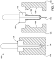
- Figure 1 illustrates a scheme 100 for injection molding a preform 105 having a tail 110 using an injection mold 115 and blowing stick 120, where the preform 105 having the tail 110 along with the blowing stick 120 can be loaded into a blow mold 125 for subsequent blow molding of a container having the tail; e.g., see Figure 3 .
- the blowing stick 120 is loaded into the injection mold 115, where a material (e.g., PET) is injection molded through port 125 to form the preform 105 having the tail 110, the preform 105 formed in-between and about a portion of the blowing stick 120 and the injection mold 115.
- the tail 110 can include part of a sprue at injection gate located at the port 130, for example.
- the blow stick 120 including the preform 105 having the tail 110 is then moved into the blow mold 125, as shown on the right side of Figure 1 , where halves of the blow mold 125 close about the preform 105 on the blowing stick 120, the blow mold 125 having an interior surface 135 determining the configuration of the subsequently blow molded container.
- the blowing stick 120 includes a passage 140 therethrough for introducing a fluid (e.g., a gas or liquid) and blow molding the preform 105 having the tail 110 into a resultant container having the tail 110; e.g., see Figure 3 .
- Figure 2 illustrates a preform 200 having a tail 205 made by injection molding, such as shown in scheme 100 of Figure 1 .
- Preforms 200 can be formed by various injection blow molding methods, employing one or more injection molds 115 and blowing sticks 120 as shown in Figure 1 , and by other injection molding methods that do not include blowing sticks 120.
- the embodiment of the preform 200 shown includes the tail 105, a support ring 210, and a threaded finish 215 proximate an open end 220 thereof.
- the embodiment of the preform 200 depicted is generally a hollow cylinder formed by injection molding from one end having the tail 205 and subsequently blow molded at the other open end 220. It is possible, however, to configure the preform 200 as other shapes, to have the tail 205 located at other positions on the preform, and configure the support ring 210 and finish 215 in other ways.
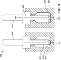
- Figure 3 illustrates a scheme 300 for blow molding of a preform 305 having a tail 310 into a container 315 having the tail 310.
- the left side of scheme 300 shows the preform 305 on a blowing stick 320 loaded into a blow mold 325 closed about the preform 305 and tail 310.
- An interior surface 330 of the blow mold 325 defines the configuration of the resultant blow molded container 315.
- the right side of scheme 300 shows a fluid 335 being injected through a passage 340 in the blowing stick 320 to expand the preform 305 to contact the interior surface 330 of the blow mold 325.
- Halves of the blow mold 325 can be separated, e.g. as shown for blow mold 125 in Figure 1 , and the container 315 having the tail 310 can be removed therefrom.
- Figure 4 illustrates a three-stage rotary injection blow molding system 400 that forms and uses a preform 405 having a tail 410 to produce a container or bottle 415 having the tail 410.
- the system 400 includes a preform injection molding station 420, a blow molding station 425, and a removal station 430 that can be sequentially interfaced using a transfer head 435 to index one or more blowing sticks 440 at each station 420, 425, 430.
- a reciprocating screw extruder 445 is used to injection mold the preform 405 having the tail 410 about a portion of the blowing stick 440 located within an injection mold 450.
- the blowing stick 440 with the preform 405 having the tail 410 is placed within a blow mold 455 and a fluid is injected through a passage 455 within the blowing stick 440 to expand the preform 405 to conform to the blow mold 455 and form the container 415 having the tail 410.
- a removal plate 465 is used to discharge the container 415 having the tail 410 from the blowing stick 440.
- the blowing stick 440 is then returned to the preform injection molding station 420.
- the system 400 can operate progressively, with each station 420, 425, 430 operating substantially simultaneously to produce a container 415 having a tail 410 every cycle following completion of the first cycle.
- the transfer head 435 can have one or more blowing sticks 440 that are rotated thereby so that one or more preforms 405 each having a tail 410 are injection molded, one or more preforms 405 each having a tail 410 are blow molded to form one or more containers 415 each having a tail 410, and one or more containers 415 each having a tail 410 are removed at the respective stations 420, 425, 430.
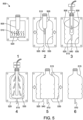
- Figure 5 illustrates a scheme 500 for injection stretch blow molding of a preform 505 having a tail 510 into a container 515 having the tail 510.
- the preform 505 having the tail 510 is heated using a heat source 520.
- the preform 505 having the tail 510 can be formed by injection molding as shown in Figure 1 , for example.
- the heated preform 505 having the tail 510 is disposed within a blow mold 525, where the blow mold 525 includes two halves that are closed about the heated preform 505 having the tail 510.
- the heated preform 505 having the tail 510 is stretched in a longitudinal direction by a stretch rod 530.
- the stretch rod 530 can have a passageway therethrough that can have one or more exit ports allowing a fluid to be injected into the stretched preform having the tail 510, as shown in the fourth stage.
- the injected fluid expands the preform 505 to contact and conform to an interior surface 535 of the blow mold 525, forming the container 515 having the tail 510.
- the tail 510 can be directed to and received within a recess 540 of the blow mold 520. As shown, the recess 540 can be formed between the two halves of the blow mold 525.
- the preform having the tail 510 is fully expanded into the container 515 having the tail 510 and the blow mold 525 halves are separated so that the container 515 can be removed therefrom.
- the sixth stage shows the resultant container 515 having the tail 510 removed from the blow mold 525.
- Figure 6 illustrates a modified scheme 600 of the third and fourth stages of the scheme 500 shown in Figure 5 , where the blow mold 525 for injection stretch blow molding of the preform 505 having the tail 510 includes a tail shaping means 605 configured to receive and shape the tail 510 during the stretch blow molding process.
- the tail shaping means 605 replaces the recess 540 from Figure 5 and serves to shape the tail 510 as the tail 510 is directed and received therein during the third stage and/or the fourth stage.
- the tail shaping means 605 receives and shapes the tail 510 into a shaped tail 610.
- the shaped tail 610 shown generally forms a hook-shape, including where the tail shaping means 605 can be of various sizes and lengths to accommodate various tails 510.
- Figure 7 illustrates a scheme 700 not embodying the invention for extrusion blow molding where a parison 705 is captured in a blow mold 710 in a way that results in the parison 705 having a tail 715 and subsequent blow molding thereof results in a container 720 having the tail 715.
- a material e.g., PET
- a base of the parison 705 is captured and squeezed by the blow mold 710 to close an end of the parison 705 and form the tail 715.
- a fluid e.g., air
- a fluid is injected into the parison 705 at 730 to expand the parison 705 having the tail 715 to conform to an interior surface 735 of the blow mold 710 and form the container 720 having the tail 715.
- the parison 705 is fully expanded to form the container 720 inside the blow mold 710.
- the fourth stage depicts the resultant container 720 having the tail 715 removed from the blow mold 710.
- Figure 8 illustrates one example 800, not embodying the invention, of a tail shaping means 805 engaging a tail 810 on a container 815.
- the container 815 having the tail 810 is moved as depicted by arrow 820 so that the tail 810 is received by the tail shaping means 805.
- the tail shaping means 805 can be moved to engage the container 815 having the tail 810.
- Pressure and/or heat can be applied to the tail 810 and/or the tail shaping means 805 so that the tail 810 conforms to a structure imposed by the tail shaping means 815.
- the tail 810 includes a thermoplastic material such as PET
- application of heat, pressure, and force can cause the tail 810 to conform to a shape or structure imposed by the tail shaping means 805 and retain that shape or structure upon cooling and/or removal of the pressure or force.
- the tail shaping means 805 depicted includes a hook-shaped channel 825 that causes the tail 810 to form a hook-shaped tail.
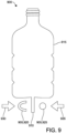
- Figure 9 illustrates another example 900, not embodying the invention, of a tail shaping means 905 engaging a tail 910 on a container 915.
- the tail shaping means 905 includes a multi-part molding operation that presses the tail 910 between a first mold part 920 and a second mold part 925 as indicated by respective arrows 930, 935. Heat and/or pressure can be applied by the first mold part 920 and the second mold part 925 to the tail 910, resulting in the tail conforming to a shaped tail complimentary to contact surfaces of the first mold part 920 and the second mold part 925.
- the tail shaping means 905 shown that includes the first mold part 920 and the second mold part 925 results in a curve being formed in the shaped tail 910, where the shaped tail can hence have a hook-shape imparted thereto.
- the presently described methods and systems can produce a container having a shaped tail by blow molding a precursor having a tail and shaping the tail to form the shaped tail.
- the present technology can be used in conjunction with other container manufacturing methods and can be used with various precursor and container materials including, for example, thermoplastic, high density polyethylene, polypropylene, polyethylene naphthalate (PEN), a PET/PEN blend or copolymer, and various multilayer structures may be suitable for the manufacture of plastic containers and used in connection with the principles described herein.
- PEN polyethylene naphthalate
- PET/PEN blend or copolymer e.g., PET/PEN blend or copolymer
- multilayer structures may be suitable for the manufacture of plastic containers and used in connection with the principles described herein.
- the present disclosure contemplates the production of PET containers, it is understood that other polyolefin materials (e.g., polyethylene, polypropylene, polyester, etc.) as well as a number of other plastics can be processed using the present technology.
- Example embodiments are provided so that this disclosure will be thorough, and will fully convey the scope to those who are skilled in the art. Numerous specific details are set forth such as examples of specific components, devices, and methods, to provide a thorough understanding of embodiments of the present disclosure. It will be apparent to those skilled in the art that specific details need not be employed, that example embodiments can be embodied in many different forms, and that neither should be construed to limit the scope of the disclosure.
Landscapes
- Engineering & Computer Science (AREA)
- Manufacturing & Machinery (AREA)
- Mechanical Engineering (AREA)
- Blow-Moulding Or Thermoforming Of Plastics Or The Like (AREA)
- Moulds For Moulding Plastics Or The Like (AREA)
Description
- The present technology relates to simultaneously forming and filling a container from a preform using a product, where the preform includes an exterior feature that is configured as a hanging implement in the resultant product-filled container.
- This section provides background information related to the present disclosure which is not necessarily prior art.
- Various products are distributed in plastic containers, such as containers formed from one or more polymers. Common polymers used to form containers include polyesters, such as polyethylene terephthalate (PET), high and low density polyethylenes, polycarbonate, and polypropylene, among others. Plastic containers can be made using various blow molding processes including injection blow molding, liquid or hydraulic blow molding, and extrusion blow molding.
- Injection blow molding can be used to form certain plastic containers in one or more stages and can include use of a stretch rod. In a two-stage injection stretch blow molding process, the plastic is first molded into a preform using an injection molding process. The preform can include the neck and finish of the container to be formed, which can include threading thereon, and a closed distal end. The preform can then be heated above the plastic glass transition temperature, optionally stretched longitudinally with a stretch rod, and blown using high-pressure gas (e.g., air) into a container conforming to a mold. As the preform is inflated, it elongates and stretches, taking on the shape of the mold cavity. The plastic solidifies upon contacting the cooler surface of the mold and the finished hollow container is subsequently ejected from the mold.
- Liquid or hydraulic blow molding can form and fill a container in a single operation. A liquid product can be used to form and fill a preform into a resultant container, where the liquid product remains thereafter in the finished container. A heated preform, much like the preform used in injection blow molding, can be placed within a mold, optionally stretched, and rapidly filled using a liquid product instead of a gas to form a container therefrom. Combination of the forming and filling steps can therefore optimize packaging of a liquid product by eliminating the transport of empty containers and time demands related to subsequent filling operations.
- Extrusion blow molding can be used to form certain plastic containers where a continuously extruded hot plastic tube or parison is captured within a mold and inflated against the inner surfaces of the mold to form a container blank. The mold can be designed to travel at the speed at which the extruded parison is moving when it closes on the parison so that the process can operate on a continuous basis. There are several different types of extrusion blow molding machines, including shuttle molds that are designed to travel in a linear motion and extrusion blow molding wheels that travel in a rotary or circular motion.
- Preforms used in injection blow molding and liquid blow molding or parisons used in extrusion blow molding can have a tail extending therefrom. For example, a preform can be formed by injection molding, where molten plastic is fed to a preform mold, the inlet to the preform mold including a channel, runner, or sprue delivering molten plastic from an extruder. Depending on the configuration of the channel and presence or location of one or more gates, the preform can include a tail extending from a point at which the molten plastic was injected into the preform mold. Likewise, when a mold captures and squeezes a hot plastic tube or parison in extrusion blow molding, a base where the parison is squeezed can result in a tail extending from the parison and from the subsequently blown container. Effort is often made to minimize any tail or extending plastic in making or forming a preform or parison, as such is typically viewed as wasted plastic material. Such tail or sprue residue, even if minimized in forming the preform or parison, can also require post-forming processing by cutting or trimming to remove what are often viewed as surface imperfections or features that may interfere with the resultant container aesthetic and/or performance.
- The present technology, conversely, seeks to convert the tail feature of a preform or parison into a useful functionality, such as a coupling point that can serve as an attachment point, hanging point, or hook, for example. Instead of configuring blow molding systems to minimize the presence of a preform or parison tail feature, and/or require post-formation processing of preforms or containers produced therefrom, the present technology deliberately provides a tail that can be shaped to complement the function of certain containers. The shaped tail can be positioned opposite an opening of the container, so that when the container is hanging from the shaped tail, contents thereof can be pulled by gravity toward the opening. In this way, the container can be stored in a position where a viscous product contained therein is maintained near a capped opening to facilitate efficient dispensing of the product.
JP 2003 080588 A claim 1. Further background information on forming containers can be obtained fromUS 5 403 538 A ,US 4395378 A ,US 2016/136867 A1 ,EP 2716430 A1 ,US 2015/231815 A1 , andJP 3 467300 B2 - The present technology includes systems, processes, and articles of manufacture that relate to a container formed and filled from a preform using a product, where the preform included an exterior feature that is formed into a hanging implement in the resultant product-filled container.
- The invention is defined in
claim 1. Optional features are defined in the dependent claims. - Further areas of applicability will become apparent from the description provided herein. The description and specific examples in this summary are intended for purposes of illustration only and are not intended to limit the scope of the present disclosure.
- The drawings described herein are for illustrative purposes only of selected embodiments and not all possible implementations, and are not intended to limit the scope of the present disclosure.
-
Figure 1 illustrates a scheme for injection molding a preform having a tail using a preform mold and blowing stick, where the preform having a tail along with the blowing stick are loaded into a mold for subsequent injection blow molding of a container having the tail. -
Figure 2 illustrates a preform having a tail made by injection molding. -
Figure 3 illustrates a scheme for injection blow molding of a preform having a tail into a container having the tail. -
Figure 4 illustrates a three-stage rotary injection blow molding system that forms and uses a preform having a tail to produce a container or bottle having the tail. -
Figure 5 illustrates a scheme for injection stretch blow molding of a preform having the tail into a container having the tail. -
Figure 6 illustrates a modified version of the scheme shown inFigure 5 , where the mold for stretch blow molding of the preform having the tail includes a tail shaping means configured to receive and shape the tail during the stretch blow molding process. -
Figure 7 illustrates a scheme for extrusion blow molding not forming a part of the present invention where a parison is captured in mold that results in the parison having a tail and subsequent blow molding thereof results in a container having the tail. -
Figure 8 illustrates a tail shaping means engaging a tail on a container. -
Figure 9 illustrates another tail shaping means engaging a tail on a container. - The following description of technology is merely exemplary in nature of the subject matter, manufacture and use of one or more inventions, and is not intended to limit the scope, application, or uses of any specific invention claimed in this application or in such other applications as can be filed claiming priority to this application, or patents issuing therefrom. Regarding methods disclosed, the order of the steps presented is exemplary in nature, and thus, the order of the steps can be different in various embodiments, including where certain steps can be simultaneously performed. "A" and "an" as used herein indicate "at least one" of the item is present; a plurality of such items can be present, when possible. Except where otherwise expressly indicated, all numerical quantities in this description are to be understood as modified by the word "about" and all geometric and spatial descriptors are to be understood as modified by the word "substantially" in describing the broadest scope of the technology. "About" when applied to numerical values indicates that the calculation or the measurement allows some slight imprecision in the value (with some approach to exactness in the value; approximately or reasonably close to the value; nearly). If, for some reason, the imprecision provided by "about" and/or "substantially" is not otherwise understood in the art with this ordinary meaning, then "about" and/or "substantially" as used herein indicates at least variations that can arise from ordinary methods of measuring or using such parameters.
- All documents, including patents, patent applications, and scientific literature cited in this detailed description are incorporated herein by reference, unless otherwise expressly indicated. Where any conflict or ambiguity can exist between a document incorporated by reference and this detailed description, the present detailed description controls.
- Although the open-ended term "comprising," as a synonym of non-restrictive terms such as including, containing, or having, is used herein to describe and claim embodiments of the present technology, embodiments can alternatively be described using more limiting terms such as "consisting of" or "consisting essentially of." Thus, for any given embodiment reciting materials, components, or process steps, the present technology also specifically includes embodiments consisting of, or consisting essentially of, such materials, components, or process steps excluding additional materials, components or processes (for consisting of) and excluding additional materials, components or processes affecting the significant properties of the embodiment (for consisting essentially of), even though such additional materials, components or processes are not explicitly recited in this application. For example, recitation of a composition or process reciting elements A, B and C specifically envisions embodiments consisting of, and consisting essentially of, A, B and C, excluding an element D that can be recited in the art, even though element D is not explicitly described as being excluded herein.
- As referred to herein, disclosures of ranges are, unless specified otherwise, inclusive of endpoints and include all distinct values and further divided ranges within the entire range. Thus, for example, a range of "from A to B" or "from about A to about B" is inclusive of A and of B. Disclosure of values and ranges of values for specific parameters (such as amounts, weight percentages, etc.) are not exclusive of other values and ranges of values useful herein. It is envisioned that two or more specific exemplified values for a given parameter can define endpoints for a range of values that can be claimed for the parameter. For example, if Parameter X is exemplified herein to have value A and also exemplified to have value Z, it is envisioned that Parameter X can have a range of values from about A to about Z. Similarly, it is envisioned that disclosure of two or more ranges of values for a parameter (whether such ranges are nested, overlapping or distinct) subsume all possible combination of ranges for the value that might be claimed using endpoints of the disclosed ranges. For example, if Parameter X is exemplified herein to have values in the range of 1-10, or 2-9, or 3-8, it is also envisioned that Parameter X can have other ranges of values including 1-9, 1-8, 1-3, 1-2, 2-10, 2-8, 2-3, 3-10, 3-9, and so on.
- When an element or layer is referred to as being "on," "engaged to," "connected to," or "coupled to" another element or layer, it can be directly on, engaged, connected or coupled to the other element or layer, or intervening elements or layers can be present. In contrast, when an element is referred to as being "directly on," "directly engaged to," "directly connected to" or "directly coupled to" another element or layer, there can be no intervening elements or layers present. Other words used to describe the relationship between elements should be interpreted in a like fashion (e.g., "between" versus "directly between," "adjacent" versus "directly adjacent," etc.). As used herein, the term "and/or" includes any and all combinations of one or more of the associated listed items.
- Although the terms first, second, third, etc. can be used herein to describe various elements, components, regions, layers and/or sections, these elements, components, regions, layers and/or sections should not be limited by these terms. These terms can be only used to distinguish one element, component, region, layer or section from another region, layer or section. Terms such as "first," "second," and other numerical terms when used herein do not imply a sequence or order unless clearly indicated by the context. Thus, a first element, component, region, layer or section discussed below could be termed a second element, component, region, layer or section without departing from the teachings of the example embodiments.
- Spatially relative terms, such as "inner," "outer," "beneath," "below," "lower," "above," "upper," and the like, can be used herein for ease of description to describe one element or feature's relationship to another element(s) or feature(s) as illustrated in the figures. Spatially relative terms can be intended to encompass different orientations of the device in use or operation in addition to the orientation depicted in the figures. For example, if the device in the figures is turned over, elements described as "below" or "beneath" other elements or features would then be oriented "above" the other elements or features. Thus, the example term "below" can encompass both an orientation of above and below. The device can be otherwise oriented (rotated 90 degrees or at other orientations) and the spatially relative descriptors used herein interpreted accordingly.
- The present technology converts a tail feature of a preform or parison into a useful functionality, such as a coupling point that can serve as an attachment point, hanging point, or hook in the resultant container, for example. The blow molding art has typically sought to minimize the presence of a preform or parison tail feature whereas the present technology deliberately provides a tail that can be shaped to complement the function of certain containers. The shaped tail can be positioned opposite an opening of the container allowing the container to depend from the shaped tail so that contents can be pulled by gravity toward the opening. In this way, the container can be stored in a position where a viscous product contained therein is maintained near the opening to facilitate efficient dispensing of the product. A container having a shaped tail is accordingly provided by blow molding a precursor having a tail and shaping the tail to form the shaped tail, to thereby produce the container having the shaped tail.
- Various types of blow molding operations can be employed. Embodiments of the invention employ injection blow molding where the precursor includes a preform having the tail. The blow molding operation includes longitudinal stretching of the preform having the tail; e.g., injection stretch blow molding using a stretch rod to longitudinally extend the preform prior or concomitant with expansion of the preform to conform to a container mold. Blow molding can include injection of a gas into the preform to inflate the preform or injection of a liquid product to expand the preform, where the liquid product can remain within the container as an end product.
- There are various ways to form the shaped tail. Shaping the tail to form the shaped tail can include engaging the tail with a tail shaping means. In certain embodiments, the tail shaping means includes a portion of a mold used to produce the container. The tail can be engaged by the tail shaping means while the precursor having the tail is blow molded to produce the container having the shaped tail.
- In certain embodiments, the tail shaping means includes a channel that receives and directs the tail into the shaped tail to produce the container having the shaped tail. The channel can have an open side allowing the shaped tail to be removed therefrom. The channel can also be heated or cooled to facilitate shaping and setting the structure of the shaped tail. The channel can also take the form of a surface, including a groove or curved surface, against which the tail is contacted so that at least a portion of the tail deviates from a longitudinal axis of the container to form the shaped tail.
- In certain embodiments, the tail shaping means shapes the tail so that at least a portion of the shaped tail deviates from a longitudinal axis of the container. The tail can be shaped into various structures that are hook-shaped, including various coupling means such as a hanging point or a hook. Where the resultant container has the shaped tail positioned opposite an opening of the container, the container can be stored depending from the shaped tail to allow any product contained therein to be drawn by gravity toward the opening. The opening can be sealed in various ways, including various valves, threaded or snap caps, flip caps, etc. Dispensing efficiency of product can therefore be maximized. For example, the container can be filled with various viscous products, such as shampoo or conditioner, adhesives, paste-like foodstuffs, etc., which can then be displayed and/or stored hanging from the shaped tail.
- The present technology further contemplates various containers having shaped tails produced by the processes described herein. Likewise, various blow molding systems for producing a container having a shaped tail and ways of using such systems are provided by the present technology. Various articles of manufacture are included, such as molds, tail shaping means, preforms, parisons, and containers. The present technology also includes various systems and system components having the features provided herein. Various articles of manufacture are provided by the present technology, including various products-by-process.
- With reference now to the several figures provided herewith, non-limiting aspects of various embodiments of the present technology are illustrated, together with various examples not embodying the invention, but provided to assist with understanding of the invention.
-
Figure 1 illustrates ascheme 100 for injection molding apreform 105 having atail 110 using aninjection mold 115 and blowingstick 120, where thepreform 105 having thetail 110 along with the blowingstick 120 can be loaded into ablow mold 125 for subsequent blow molding of a container having the tail; e.g., seeFigure 3 . In the left side ofFigure 1 , the blowingstick 120 is loaded into theinjection mold 115, where a material (e.g., PET) is injection molded throughport 125 to form thepreform 105 having thetail 110, thepreform 105 formed in-between and about a portion of the blowingstick 120 and theinjection mold 115. Thetail 110 can include part of a sprue at injection gate located at theport 130, for example. Theblow stick 120 including thepreform 105 having thetail 110 is then moved into theblow mold 125, as shown on the right side ofFigure 1 , where halves of theblow mold 125 close about thepreform 105 on the blowingstick 120, theblow mold 125 having aninterior surface 135 determining the configuration of the subsequently blow molded container. As shown, the blowingstick 120 includes apassage 140 therethrough for introducing a fluid (e.g., a gas or liquid) and blow molding thepreform 105 having thetail 110 into a resultant container having thetail 110; e.g., seeFigure 3 . -
Figure 2 illustrates apreform 200 having atail 205 made by injection molding, such as shown inscheme 100 ofFigure 1 .Preforms 200 can be formed by various injection blow molding methods, employing one ormore injection molds 115 and blowingsticks 120 as shown inFigure 1 , and by other injection molding methods that do not include blowing sticks 120. The embodiment of thepreform 200 shown includes thetail 105, asupport ring 210, and a threadedfinish 215 proximate anopen end 220 thereof. As such, the embodiment of thepreform 200 depicted is generally a hollow cylinder formed by injection molding from one end having thetail 205 and subsequently blow molded at the otheropen end 220. It is possible, however, to configure thepreform 200 as other shapes, to have thetail 205 located at other positions on the preform, and configure thesupport ring 210 and finish 215 in other ways. -
Figure 3 illustrates ascheme 300 for blow molding of apreform 305 having atail 310 into acontainer 315 having thetail 310. The left side ofscheme 300 shows thepreform 305 on a blowingstick 320 loaded into ablow mold 325 closed about thepreform 305 andtail 310. Aninterior surface 330 of theblow mold 325 defines the configuration of the resultant blow moldedcontainer 315. The right side ofscheme 300 shows a fluid 335 being injected through apassage 340 in the blowingstick 320 to expand thepreform 305 to contact theinterior surface 330 of theblow mold 325. Halves of theblow mold 325 can be separated, e.g. as shown forblow mold 125 inFigure 1 , and thecontainer 315 having thetail 310 can be removed therefrom. -
Figure 4 illustrates a three-stage rotary injection blowmolding system 400 that forms and uses apreform 405 having atail 410 to produce a container orbottle 415 having thetail 410. Thesystem 400 includes a preforminjection molding station 420, ablow molding station 425, and aremoval station 430 that can be sequentially interfaced using atransfer head 435 to index one or more blowing sticks 440 at eachstation injection molding station 420, areciprocating screw extruder 445 is used to injection mold thepreform 405 having thetail 410 about a portion of the blowingstick 440 located within aninjection mold 450. At theblow molding station 425, the blowingstick 440 with thepreform 405 having thetail 410 is placed within ablow mold 455 and a fluid is injected through apassage 455 within the blowingstick 440 to expand thepreform 405 to conform to theblow mold 455 and form thecontainer 415 having thetail 410. At theremoval station 430, aremoval plate 465 is used to discharge thecontainer 415 having thetail 410 from the blowingstick 440. The blowingstick 440 is then returned to the preforminjection molding station 420. Thesystem 400 can operate progressively, with eachstation container 415 having atail 410 every cycle following completion of the first cycle. For example, thetransfer head 435 can have one or more blowing sticks 440 that are rotated thereby so that one ormore preforms 405 each having atail 410 are injection molded, one ormore preforms 405 each having atail 410 are blow molded to form one ormore containers 415 each having atail 410, and one ormore containers 415 each having atail 410 are removed at therespective stations -
Figure 5 illustrates ascheme 500 for injection stretch blow molding of apreform 505 having atail 510 into acontainer 515 having thetail 510. In a first stage, thepreform 505 having thetail 510 is heated using aheat source 520. Thepreform 505 having thetail 510 can be formed by injection molding as shown inFigure 1 , for example. In a second stage, theheated preform 505 having thetail 510 is disposed within ablow mold 525, where theblow mold 525 includes two halves that are closed about theheated preform 505 having thetail 510. In a third stage, theheated preform 505 having thetail 510 is stretched in a longitudinal direction by astretch rod 530. Thestretch rod 530 can have a passageway therethrough that can have one or more exit ports allowing a fluid to be injected into the stretched preform having thetail 510, as shown in the fourth stage. The injected fluid expands thepreform 505 to contact and conform to aninterior surface 535 of theblow mold 525, forming thecontainer 515 having thetail 510. During the third stage and/or the fourth stage, thetail 510 can be directed to and received within arecess 540 of theblow mold 520. As shown, therecess 540 can be formed between the two halves of theblow mold 525. In a fifth stage, the preform having thetail 510 is fully expanded into thecontainer 515 having thetail 510 and theblow mold 525 halves are separated so that thecontainer 515 can be removed therefrom. The sixth stage shows theresultant container 515 having thetail 510 removed from theblow mold 525. -
Figure 6 illustrates a modifiedscheme 600 of the third and fourth stages of thescheme 500 shown inFigure 5 , where theblow mold 525 for injection stretch blow molding of thepreform 505 having thetail 510 includes a tail shaping means 605 configured to receive and shape thetail 510 during the stretch blow molding process. The tail shaping means 605 replaces therecess 540 fromFigure 5 and serves to shape thetail 510 as thetail 510 is directed and received therein during the third stage and/or the fourth stage. As shown inFigure 6 , the tail shaping means 605 receives and shapes thetail 510 into a shapedtail 610. The shapedtail 610 shown generally forms a hook-shape, including where the tail shaping means 605 can be of various sizes and lengths to accommodatevarious tails 510. -
Figure 7 illustrates ascheme 700 not embodying the invention for extrusion blow molding where aparison 705 is captured in ablow mold 710 in a way that results in theparison 705 having atail 715 and subsequent blow molding thereof results in acontainer 720 having thetail 715. In a first stage, a material (e.g., PET) is extruded at 725 to form a continuous and hollow tube-like structure that forms theparison 705. In a second stage, a base of theparison 705 is captured and squeezed by theblow mold 710 to close an end of theparison 705 and form thetail 715. A fluid (e.g., air) is injected into theparison 705 at 730 to expand theparison 705 having thetail 715 to conform to aninterior surface 735 of theblow mold 710 and form thecontainer 720 having thetail 715. As can be seen in the third stage, theparison 705 is fully expanded to form thecontainer 720 inside theblow mold 710. The fourth stage depicts theresultant container 720 having thetail 715 removed from theblow mold 710. -
Figure 8 illustrates one example 800, not embodying the invention, of a tail shaping means 805 engaging atail 810 on acontainer 815. Here, thecontainer 815 having thetail 810 is moved as depicted byarrow 820 so that thetail 810 is received by the tail shaping means 805. Alternatively, the tail shaping means 805 can be moved to engage thecontainer 815 having thetail 810. Pressure and/or heat can be applied to thetail 810 and/or the tail shaping means 805 so that thetail 810 conforms to a structure imposed by the tail shaping means 815. For example, where thetail 810 includes a thermoplastic material such as PET, application of heat, pressure, and force can cause thetail 810 to conform to a shape or structure imposed by the tail shaping means 805 and retain that shape or structure upon cooling and/or removal of the pressure or force. The tail shaping means 805 depicted includes a hook-shapedchannel 825 that causes thetail 810 to form a hook-shaped tail. -
Figure 9 illustrates another example 900, not embodying the invention, of a tail shaping means 905 engaging atail 910 on acontainer 915. Here, the tail shaping means 905 includes a multi-part molding operation that presses thetail 910 between a first mold part 920 and a second mold part 925 as indicated byrespective arrows tail 910, resulting in the tail conforming to a shaped tail complimentary to contact surfaces of the first mold part 920 and the second mold part 925. The tail shaping means 905 shown that includes the first mold part 920 and the second mold part 925 results in a curve being formed in the shapedtail 910, where the shaped tail can hence have a hook-shape imparted thereto. - As these examples illustrate, the presently described methods and systems can produce a container having a shaped tail by blow molding a precursor having a tail and shaping the tail to form the shaped tail. However, it is understood that the present technology can be used in conjunction with other container manufacturing methods and can be used with various precursor and container materials including, for example, thermoplastic, high density polyethylene, polypropylene, polyethylene naphthalate (PEN), a PET/PEN blend or copolymer, and various multilayer structures may be suitable for the manufacture of plastic containers and used in connection with the principles described herein. While the present disclosure contemplates the production of PET containers, it is understood that other polyolefin materials (e.g., polyethylene, polypropylene, polyester, etc.) as well as a number of other plastics can be processed using the present technology.
- Example embodiments are provided so that this disclosure will be thorough, and will fully convey the scope to those who are skilled in the art. Numerous specific details are set forth such as examples of specific components, devices, and methods, to provide a thorough understanding of embodiments of the present disclosure. It will be apparent to those skilled in the art that specific details need not be employed, that example embodiments can be embodied in many different forms, and that neither should be construed to limit the scope of the disclosure.
Claims (6)
- A process for producing a container having a shaped tail, the process comprising:heating a preform (505) having a tail (510);injection blow molding the heated preform (505) having the tail (510), wherein the injection blow molding comprises longitudinal stretching of the heated preform having the tail, wherein a blow mold (525) utilized during the injection blow molding includes two halves that are closed about the heated preform (505) having the tail (510); andshaping the tail (510) to form the shaped tail (610), wherein shaping the tail (510) to form the shaped tail (610) includes engaging the tail (510) with a tail shaping means (605),characterized in that the tail shaping means (605) is provided as a channel formed between the two halves of the blow mold (525) that receives and directs the tail (510) into the shaped tail (610) during the longitudinal stretching of the heated preform (505) having the tail (510), wherein the channel includes a curved surface against which the tail is contacted during the longitudinal stretching of the heated preform (505) having the tail (510) so that at least a portion of the tail deviates from a longitudinal axis of the container to shape the tail into a hook-shape;thereby producing the container having the shaped tail (610), the shaped tail (610) being hook-shaped.
- The process of Claim 1, wherein the blow molding comprises injection blow molding using a gas.
- The process of Claim 1, wherein the blow molding comprises injection blow molding using a liquid product that remains within the container as an end product.
- The process of Claim 1, wherein the tail (510) is engaged by the tail shaping means while the heated preform (505) having the tail (510) is blow molded to produce the container having the shaped tail (610).
- The process of Claim 4, wherein the tail shaping means shapes the tail into a coupling means.
- The process of Claim 4, wherein the tail shaping means shapes the tail into a hanging point.
Applications Claiming Priority (1)
| Application Number | Priority Date | Filing Date | Title |
|---|---|---|---|
| PCT/IB2020/055799 WO2021255505A1 (en) | 2020-06-19 | 2020-06-19 | Method of forming a container having a hanging implement |
Publications (2)
| Publication Number | Publication Date |
|---|---|
| EP4168236A1 EP4168236A1 (en) | 2023-04-26 |
| EP4168236B1 true EP4168236B1 (en) | 2024-11-27 |
Family
ID=71738202
Family Applications (1)
| Application Number | Title | Priority Date | Filing Date |
|---|---|---|---|
| EP20743791.4A Active EP4168236B1 (en) | 2020-06-19 | 2020-06-19 | Method of forming a container having a hanging implement |
Country Status (4)
| Country | Link |
|---|---|
| US (1) | US12296523B2 (en) |
| EP (1) | EP4168236B1 (en) |
| CN (1) | CN115702074B (en) |
| WO (1) | WO2021255505A1 (en) |
Family Cites Families (17)
| Publication number | Priority date | Publication date | Assignee | Title |
|---|---|---|---|---|
| DE2400951A1 (en) * | 1974-01-09 | 1975-07-17 | 4 P Verpackungen Gmbh | METHOD AND DEVICE FOR THE MANUFACTURING OF PLASTIC BOTTLES |
| US4395378A (en) | 1981-05-14 | 1983-07-26 | Sewell Plastics, Inc. | Method for making an injection stretch blow molded container with an integral tab |
| DE69026793D1 (en) * | 1989-11-16 | 1996-06-05 | Mitsui Petrochemical Ind | Hanging handle container and process for its manufacture |
| JPH0684038B2 (en) * | 1990-10-27 | 1994-10-26 | 日精エー・エス・ビー機械株式会社 | Preform for forming container with hanging device and method for forming container with hanging device |
| JP3467300B2 (en) * | 1993-11-29 | 2003-11-17 | 日精エー・エス・ビー機械株式会社 | Container with hanging device |
| JP2003080588A (en) * | 2001-09-13 | 2003-03-19 | Hanshin Kasei Kogyo Kk | Container with hanging device |
| JP4774660B2 (en) * | 2001-09-17 | 2011-09-14 | 東洋製罐株式会社 | Molding method of container with lifting tool |
| JP2003104376A (en) * | 2001-09-28 | 2003-04-09 | Aoki Technical Laboratory Inc | Plastic bottle with hanger at bottom |
| JP2005169698A (en) * | 2003-12-09 | 2005-06-30 | Sahara Kagaku Kogyo Kk | Method for forming projection to molded product by biaxial stretch/blow molding method |
| DE102007056486B4 (en) * | 2007-11-22 | 2009-12-17 | Fresenius Kabi Deutschland Gmbh | Preform and method of manufacturing a container for holding liquids for medical applications |
| JPWO2012161150A1 (en) * | 2011-05-24 | 2014-07-31 | エイワイファーマ株式会社 | Preform, synthetic resin-made container with hanging tool, and method for forming container with hanging tool |
| WO2013063461A1 (en) * | 2011-10-27 | 2013-05-02 | Amcor Limited | Counter stretch connecting rod and positive fill level control rod |
| US20140054829A1 (en) * | 2012-08-22 | 2014-02-27 | Altira, Inc. | Container with end feature and method of making same |
| EP2823949A1 (en) * | 2013-07-08 | 2015-01-14 | ISP Technology AG | Plastic connection seam, plastic bottle with seam and method for their preparation |
| WO2015123760A1 (en) * | 2014-02-19 | 2015-08-27 | Medonyx Inc. | An open-clip blow molding method and a blow molded article which integrally provide a clip for securement to another item |
| KR101975644B1 (en) * | 2014-06-20 | 2019-05-07 | 닛세이 에이. 에스. 비 기카이 가부시키가이샤 | Manufacturing method and manufacturing apparatus for hollow container |
| JP7183379B2 (en) * | 2019-02-28 | 2022-12-05 | 日精エー・エス・ビー機械株式会社 | Container mold and container manufacturing method |
-
2020
- 2020-06-19 EP EP20743791.4A patent/EP4168236B1/en active Active
- 2020-06-19 US US18/001,608 patent/US12296523B2/en active Active
- 2020-06-19 CN CN202080102144.1A patent/CN115702074B/en active Active
- 2020-06-19 WO PCT/IB2020/055799 patent/WO2021255505A1/en not_active Ceased
Also Published As
| Publication number | Publication date |
|---|---|
| CN115702074A (en) | 2023-02-14 |
| US20230226740A1 (en) | 2023-07-20 |
| CN115702074B (en) | 2025-12-23 |
| US12296523B2 (en) | 2025-05-13 |
| WO2021255505A1 (en) | 2021-12-23 |
| EP4168236A1 (en) | 2023-04-26 |
Similar Documents
| Publication | Publication Date | Title |
|---|---|---|
| EP1853416B1 (en) | Process for the manufacture of containers which have an integral handle | |
| CN103391839B (en) | Reverse tension rods for machine hygiene and processing | |
| AU2011302329B2 (en) | Hydroblow preform design | |
| US3940225A (en) | Blow molding apparatus for staged inflation of an extruded parison | |
| CN106604808A (en) | Blow molded containers and their manufacture | |
| US12296523B2 (en) | Method of forming a container having a hanging implement | |
| US20240083093A1 (en) | Reduced material container and method of forming same | |
| US20040159983A1 (en) | Method and apparatus for blow-molding an article having a solid radially outwardly projecting flange | |
| CN112272605A (en) | Method of extrusion blow molding using liquid | |
| CN110799322A (en) | Blow molding method using liquid | |
| EP1688235A1 (en) | Process for blow-molding a container comprising a handle | |
| EP4168237B1 (en) | Container forming and filling system with hydrophobic properties | |
| US12390977B2 (en) | Method of fluid forming and filling containers | |
| US11040475B2 (en) | Vertically added processing for blow molding machine | |
| WO2012044431A1 (en) | Blow needle for extrusion blow molding pet and method of blow molding an article from a parison comprising epet |
Legal Events
| Date | Code | Title | Description |
|---|---|---|---|
| STAA | Information on the status of an ep patent application or granted ep patent |
Free format text: STATUS: UNKNOWN |
|
| STAA | Information on the status of an ep patent application or granted ep patent |
Free format text: STATUS: THE INTERNATIONAL PUBLICATION HAS BEEN MADE |
|
| PUAI | Public reference made under article 153(3) epc to a published international application that has entered the european phase |
Free format text: ORIGINAL CODE: 0009012 |
|
| STAA | Information on the status of an ep patent application or granted ep patent |
Free format text: STATUS: REQUEST FOR EXAMINATION WAS MADE |
|
| 17P | Request for examination filed |
Effective date: 20221122 |
|
| AK | Designated contracting states |
Kind code of ref document: A1 Designated state(s): AL AT BE BG CH CY CZ DE DK EE ES FI FR GB GR HR HU IE IS IT LI LT LU LV MC MK MT NL NO PL PT RO RS SE SI SK SM TR |
|
| DAV | Request for validation of the european patent (deleted) | ||
| DAX | Request for extension of the european patent (deleted) | ||
| P01 | Opt-out of the competence of the unified patent court (upc) registered |
Effective date: 20230925 |
|
| GRAP | Despatch of communication of intention to grant a patent |
Free format text: ORIGINAL CODE: EPIDOSNIGR1 |
|
| STAA | Information on the status of an ep patent application or granted ep patent |
Free format text: STATUS: GRANT OF PATENT IS INTENDED |
|
| INTG | Intention to grant announced |
Effective date: 20240620 |
|
| GRAS | Grant fee paid |
Free format text: ORIGINAL CODE: EPIDOSNIGR3 |
|
| GRAA | (expected) grant |
Free format text: ORIGINAL CODE: 0009210 |
|
| STAA | Information on the status of an ep patent application or granted ep patent |
Free format text: STATUS: THE PATENT HAS BEEN GRANTED |
|
| AK | Designated contracting states |
Kind code of ref document: B1 Designated state(s): AL AT BE BG CH CY CZ DE DK EE ES FI FR GB GR HR HU IE IS IT LI LT LU LV MC MK MT NL NO PL PT RO RS SE SI SK SM TR |
|
| REG | Reference to a national code |
Ref country code: GB Ref legal event code: FG4D |
|
| REG | Reference to a national code |
Ref country code: CH Ref legal event code: EP |
|
| REG | Reference to a national code |
Ref country code: IE Ref legal event code: FG4D |
|
| REG | Reference to a national code |
Ref country code: DE Ref legal event code: R096 Ref document number: 602020042056 Country of ref document: DE |
|
| REG | Reference to a national code |
Ref country code: LT Ref legal event code: MG9D |
|
| REG | Reference to a national code |
Ref country code: NL Ref legal event code: MP Effective date: 20241127 |
|
| PG25 | Lapsed in a contracting state [announced via postgrant information from national office to epo] |
Ref country code: IS Free format text: LAPSE BECAUSE OF FAILURE TO SUBMIT A TRANSLATION OF THE DESCRIPTION OR TO PAY THE FEE WITHIN THE PRESCRIBED TIME-LIMIT Effective date: 20250327 Ref country code: PT Free format text: LAPSE BECAUSE OF FAILURE TO SUBMIT A TRANSLATION OF THE DESCRIPTION OR TO PAY THE FEE WITHIN THE PRESCRIBED TIME-LIMIT Effective date: 20250327 Ref country code: HR Free format text: LAPSE BECAUSE OF FAILURE TO SUBMIT A TRANSLATION OF THE DESCRIPTION OR TO PAY THE FEE WITHIN THE PRESCRIBED TIME-LIMIT Effective date: 20241127 |
|
| PG25 | Lapsed in a contracting state [announced via postgrant information from national office to epo] |
Ref country code: NL Free format text: LAPSE BECAUSE OF FAILURE TO SUBMIT A TRANSLATION OF THE DESCRIPTION OR TO PAY THE FEE WITHIN THE PRESCRIBED TIME-LIMIT Effective date: 20241127 Ref country code: FI Free format text: LAPSE BECAUSE OF FAILURE TO SUBMIT A TRANSLATION OF THE DESCRIPTION OR TO PAY THE FEE WITHIN THE PRESCRIBED TIME-LIMIT Effective date: 20241127 |
|
| REG | Reference to a national code |
Ref country code: AT Ref legal event code: MK05 Ref document number: 1745320 Country of ref document: AT Kind code of ref document: T Effective date: 20241127 |
|
| PG25 | Lapsed in a contracting state [announced via postgrant information from national office to epo] |
Ref country code: BG Free format text: LAPSE BECAUSE OF FAILURE TO SUBMIT A TRANSLATION OF THE DESCRIPTION OR TO PAY THE FEE WITHIN THE PRESCRIBED TIME-LIMIT Effective date: 20241127 |
|
| PG25 | Lapsed in a contracting state [announced via postgrant information from national office to epo] |
Ref country code: ES Free format text: LAPSE BECAUSE OF FAILURE TO SUBMIT A TRANSLATION OF THE DESCRIPTION OR TO PAY THE FEE WITHIN THE PRESCRIBED TIME-LIMIT Effective date: 20241127 |
|
| PG25 | Lapsed in a contracting state [announced via postgrant information from national office to epo] |
Ref country code: NO Free format text: LAPSE BECAUSE OF FAILURE TO SUBMIT A TRANSLATION OF THE DESCRIPTION OR TO PAY THE FEE WITHIN THE PRESCRIBED TIME-LIMIT Effective date: 20250227 |
|
| PG25 | Lapsed in a contracting state [announced via postgrant information from national office to epo] |
Ref country code: GR Free format text: LAPSE BECAUSE OF FAILURE TO SUBMIT A TRANSLATION OF THE DESCRIPTION OR TO PAY THE FEE WITHIN THE PRESCRIBED TIME-LIMIT Effective date: 20250228 Ref country code: LV Free format text: LAPSE BECAUSE OF FAILURE TO SUBMIT A TRANSLATION OF THE DESCRIPTION OR TO PAY THE FEE WITHIN THE PRESCRIBED TIME-LIMIT Effective date: 20241127 Ref country code: AT Free format text: LAPSE BECAUSE OF FAILURE TO SUBMIT A TRANSLATION OF THE DESCRIPTION OR TO PAY THE FEE WITHIN THE PRESCRIBED TIME-LIMIT Effective date: 20241127 |
|
| PG25 | Lapsed in a contracting state [announced via postgrant information from national office to epo] |
Ref country code: PL Free format text: LAPSE BECAUSE OF FAILURE TO SUBMIT A TRANSLATION OF THE DESCRIPTION OR TO PAY THE FEE WITHIN THE PRESCRIBED TIME-LIMIT Effective date: 20241127 |
|
| PG25 | Lapsed in a contracting state [announced via postgrant information from national office to epo] |
Ref country code: RS Free format text: LAPSE BECAUSE OF FAILURE TO SUBMIT A TRANSLATION OF THE DESCRIPTION OR TO PAY THE FEE WITHIN THE PRESCRIBED TIME-LIMIT Effective date: 20250227 |
|
| PG25 | Lapsed in a contracting state [announced via postgrant information from national office to epo] |
Ref country code: SM Free format text: LAPSE BECAUSE OF FAILURE TO SUBMIT A TRANSLATION OF THE DESCRIPTION OR TO PAY THE FEE WITHIN THE PRESCRIBED TIME-LIMIT Effective date: 20241127 |
|
| PGFP | Annual fee paid to national office [announced via postgrant information from national office to epo] |
Ref country code: DE Payment date: 20250528 Year of fee payment: 6 |
|
| PG25 | Lapsed in a contracting state [announced via postgrant information from national office to epo] |
Ref country code: DK Free format text: LAPSE BECAUSE OF FAILURE TO SUBMIT A TRANSLATION OF THE DESCRIPTION OR TO PAY THE FEE WITHIN THE PRESCRIBED TIME-LIMIT Effective date: 20241127 |
|
| PGFP | Annual fee paid to national office [announced via postgrant information from national office to epo] |
Ref country code: IT Payment date: 20250528 Year of fee payment: 6 |
|
| PG25 | Lapsed in a contracting state [announced via postgrant information from national office to epo] |
Ref country code: EE Free format text: LAPSE BECAUSE OF FAILURE TO SUBMIT A TRANSLATION OF THE DESCRIPTION OR TO PAY THE FEE WITHIN THE PRESCRIBED TIME-LIMIT Effective date: 20241127 |
|
| PGFP | Annual fee paid to national office [announced via postgrant information from national office to epo] |
Ref country code: FR Payment date: 20250610 Year of fee payment: 6 |
|
| PG25 | Lapsed in a contracting state [announced via postgrant information from national office to epo] |
Ref country code: RO Free format text: LAPSE BECAUSE OF FAILURE TO SUBMIT A TRANSLATION OF THE DESCRIPTION OR TO PAY THE FEE WITHIN THE PRESCRIBED TIME-LIMIT Effective date: 20241127 |
|
| PG25 | Lapsed in a contracting state [announced via postgrant information from national office to epo] |
Ref country code: SK Free format text: LAPSE BECAUSE OF FAILURE TO SUBMIT A TRANSLATION OF THE DESCRIPTION OR TO PAY THE FEE WITHIN THE PRESCRIBED TIME-LIMIT Effective date: 20241127 |
|
| PG25 | Lapsed in a contracting state [announced via postgrant information from national office to epo] |
Ref country code: CZ Free format text: LAPSE BECAUSE OF FAILURE TO SUBMIT A TRANSLATION OF THE DESCRIPTION OR TO PAY THE FEE WITHIN THE PRESCRIBED TIME-LIMIT Effective date: 20241127 |
|
| REG | Reference to a national code |
Ref country code: DE Ref legal event code: R097 Ref document number: 602020042056 Country of ref document: DE |
|
| PG25 | Lapsed in a contracting state [announced via postgrant information from national office to epo] |
Ref country code: SE Free format text: LAPSE BECAUSE OF FAILURE TO SUBMIT A TRANSLATION OF THE DESCRIPTION OR TO PAY THE FEE WITHIN THE PRESCRIBED TIME-LIMIT Effective date: 20241127 |
|
| PLBE | No opposition filed within time limit |
Free format text: ORIGINAL CODE: 0009261 |
|
| STAA | Information on the status of an ep patent application or granted ep patent |
Free format text: STATUS: NO OPPOSITION FILED WITHIN TIME LIMIT |
|
| PGFP | Annual fee paid to national office [announced via postgrant information from national office to epo] |
Ref country code: CH Payment date: 20250701 Year of fee payment: 6 |
|
| 26N | No opposition filed |
Effective date: 20250828 |
|
| PG25 | Lapsed in a contracting state [announced via postgrant information from national office to epo] |
Ref country code: MC Free format text: LAPSE BECAUSE OF FAILURE TO SUBMIT A TRANSLATION OF THE DESCRIPTION OR TO PAY THE FEE WITHIN THE PRESCRIBED TIME-LIMIT Effective date: 20241127 |
|
| PG25 | Lapsed in a contracting state [announced via postgrant information from national office to epo] |
Ref country code: LU Free format text: LAPSE BECAUSE OF NON-PAYMENT OF DUE FEES Effective date: 20250619 |
|
| GBPC | Gb: european patent ceased through non-payment of renewal fee |
Effective date: 20250619 |
|
| REG | Reference to a national code |
Ref country code: BE Ref legal event code: MM Effective date: 20250630 |
|
| PG25 | Lapsed in a contracting state [announced via postgrant information from national office to epo] |
Ref country code: GB Free format text: LAPSE BECAUSE OF NON-PAYMENT OF DUE FEES Effective date: 20250619 |
|
| PG25 | Lapsed in a contracting state [announced via postgrant information from national office to epo] |
Ref country code: IE Free format text: LAPSE BECAUSE OF NON-PAYMENT OF DUE FEES Effective date: 20250619 |
|
| PG25 | Lapsed in a contracting state [announced via postgrant information from national office to epo] |
Ref country code: BE Free format text: LAPSE BECAUSE OF NON-PAYMENT OF DUE FEES Effective date: 20250630 |
|
| PG25 | Lapsed in a contracting state [announced via postgrant information from national office to epo] |
Ref country code: LT Free format text: LAPSE BECAUSE OF FAILURE TO SUBMIT A TRANSLATION OF THE DESCRIPTION OR TO PAY THE FEE WITHIN THE PRESCRIBED TIME-LIMIT Effective date: 20241127 |
|
| PG25 | Lapsed in a contracting state [announced via postgrant information from national office to epo] |
Ref country code: CY Free format text: LAPSE BECAUSE OF FAILURE TO SUBMIT A TRANSLATION OF THE DESCRIPTION OR TO PAY THE FEE WITHIN THE PRESCRIBED TIME-LIMIT Effective date: 20241127 |