EP4167902B1 - Medizinische vorrichtung und verfahren zur erkennung einer positionsänderung - Google Patents
Medizinische vorrichtung und verfahren zur erkennung einer positionsänderung Download PDFInfo
- Publication number
- EP4167902B1 EP4167902B1 EP21740122.3A EP21740122A EP4167902B1 EP 4167902 B1 EP4167902 B1 EP 4167902B1 EP 21740122 A EP21740122 A EP 21740122A EP 4167902 B1 EP4167902 B1 EP 4167902B1
- Authority
- EP
- European Patent Office
- Prior art keywords
- sensor
- pressure
- medical device
- housing
- human
- Prior art date
- Legal status (The legal status is an assumption and is not a legal conclusion. Google has not performed a legal analysis and makes no representation as to the accuracy of the status listed.)
- Active
Links
Images


Classifications
-
- A—HUMAN NECESSITIES
- A61—MEDICAL OR VETERINARY SCIENCE; HYGIENE
- A61F—FILTERS IMPLANTABLE INTO BLOOD VESSELS; PROSTHESES; DEVICES PROVIDING PATENCY TO, OR PREVENTING COLLAPSING OF, TUBULAR STRUCTURES OF THE BODY, e.g. STENTS; ORTHOPAEDIC, NURSING OR CONTRACEPTIVE DEVICES; FOMENTATION; TREATMENT OR PROTECTION OF EYES OR EARS; BANDAGES, DRESSINGS OR ABSORBENT PADS; FIRST-AID KITS
- A61F5/00—Orthopaedic methods or devices for non-surgical treatment of bones or joints; Nursing devices ; Anti-rape devices
- A61F5/48—Devices for preventing wetting or pollution of the bed
-
- A—HUMAN NECESSITIES
- A61—MEDICAL OR VETERINARY SCIENCE; HYGIENE
- A61F—FILTERS IMPLANTABLE INTO BLOOD VESSELS; PROSTHESES; DEVICES PROVIDING PATENCY TO, OR PREVENTING COLLAPSING OF, TUBULAR STRUCTURES OF THE BODY, e.g. STENTS; ORTHOPAEDIC, NURSING OR CONTRACEPTIVE DEVICES; FOMENTATION; TREATMENT OR PROTECTION OF EYES OR EARS; BANDAGES, DRESSINGS OR ABSORBENT PADS; FIRST-AID KITS
- A61F2/00—Filters implantable into blood vessels; Prostheses, i.e. artificial substitutes or replacements for parts of the body; Appliances for connecting them with the body; Devices providing patency to, or preventing collapsing of, tubular structures of the body, e.g. stents
- A61F2/0004—Closure means for urethra or rectum, i.e. anti-incontinence devices or support slings against pelvic prolapse
- A61F2/0031—Closure means for urethra or rectum, i.e. anti-incontinence devices or support slings against pelvic prolapse for constricting the lumen; Support slings for the urethra
- A61F2/0036—Closure means for urethra or rectum, i.e. anti-incontinence devices or support slings against pelvic prolapse for constricting the lumen; Support slings for the urethra implantable
- A61F2/004—Closure means for urethra or rectum, i.e. anti-incontinence devices or support slings against pelvic prolapse for constricting the lumen; Support slings for the urethra implantable inflatable
-
- A—HUMAN NECESSITIES
- A61—MEDICAL OR VETERINARY SCIENCE; HYGIENE
- A61B—DIAGNOSIS; SURGERY; IDENTIFICATION
- A61B2562/00—Details of sensors; Constructional details of sensor housings or probes; Accessories for sensors
- A61B2562/02—Details of sensors specially adapted for in-vivo measurements
- A61B2562/0219—Inertial sensors, e.g. accelerometers, gyroscopes, tilt switches
-
- A—HUMAN NECESSITIES
- A61—MEDICAL OR VETERINARY SCIENCE; HYGIENE
- A61F—FILTERS IMPLANTABLE INTO BLOOD VESSELS; PROSTHESES; DEVICES PROVIDING PATENCY TO, OR PREVENTING COLLAPSING OF, TUBULAR STRUCTURES OF THE BODY, e.g. STENTS; ORTHOPAEDIC, NURSING OR CONTRACEPTIVE DEVICES; FOMENTATION; TREATMENT OR PROTECTION OF EYES OR EARS; BANDAGES, DRESSINGS OR ABSORBENT PADS; FIRST-AID KITS
- A61F2250/00—Special features of prostheses classified in groups A61F2/00 - A61F2/26 or A61F2/82 or A61F9/00 or A61F11/00 or subgroups thereof
- A61F2250/0058—Additional features; Implant or prostheses properties not otherwise provided for
- A61F2250/0096—Markers and sensors for detecting a position or changes of a position of an implant, e.g. RF sensors, ultrasound markers
Definitions
- the present invention relates to a medical device implantable in a human or animal body.
- the invention relates in particular to active implantable medical devices, i.e. medical devices dependent for their operation on a source of electrical energy and their configuration for the detection of a change in position of at least one part of the human or animal body.
- Implantable medical devices that perform a function in the patient's body, for example to compensate for the dysfunction of a natural organ such as a sphincter in the case of urinary incontinence or to act by applying a particular therapy as is the case with a pacemaker or a neurostimulator.
- urinary incontinence is a disability that affects both women and men.
- This disability can be defined as an involuntary loss of urine through the urethra. In most cases, this is due to a weakening of the pelvic support or the bladder/sphincter block.
- the incontinence is said to be "severe” and then requires the fitting of a prosthesis to allow the patient to return to a normal social life.
- severe incontinence the most commonly used method is to install an artificial urinary sphincter.
- Implantable medical devices are known that are intended to selectively close an anatomical conduit, for example to treat incontinence (case of artificial urinary and anal sphincters).
- the anatomical conduit is generally closed by the compression exerted by a cuff wrapped around said conduit.
- the first part consists of a deformable element of the occlusive cuff type placed around the urethra, possibly the bladder neck during implantation in women, exerting circumferential urethral pressure thanks to a cushion filled with liquid thus ensuring the patient's continence.
- the second is a regulating balloon which allows, when filled with a certain volume of liquid, to create a constant hydraulic pressure. The regulating pressure is chosen according to the patient during the operation, this cannot be modified once the prosthesis is implanted.
- a manual pump is required, the third part, ensuring the opening of the urethral part compressed by the cuff. This pump is composed of a bulb, a resistor and two valves which ensure the circulation of the liquid to or from the occlusive cuff.
- the fluid is transferred from the cuff to the regulating balloon: the pressure exerted on the urethra then becomes negligible compared to the bladder pressure.
- the urine can then flow freely out of the bladder.
- the liquid is transferred from the balloon to the cuff thanks to the pressure exerted on the resistor by the regulating balloon, the urethra is occluded again.
- This passive prosthesis has a number of drawbacks.
- the pressure regulating the cuff can only be adapted at the time of fitting the prosthesis, which could cause problems if the pathology evolves over time so that the pressure at the urethra would have to be modified to meet the patient's needs or even in the event of a change in posture or physical activity which could lead to a variation in the pressure exerted on the sphincter and on the cuff.
- this system does not offer satisfactory comfort because the patient must activate the pump each time it is necessary, and the control is not easy since it is necessary to hold the pump manually during urination on the one hand and to press it forcefully on the other hand. Indeed, this is all the more problematic since the control pump is located in the scrotum in men and in one of the labia majora in women.
- this prosthesis involves significant compression of the urethra in an almost continuous manner, regardless of the posture and the level of compression required, which can lead to urethral atrophy. Indeed, since the prosthesis only works at a single urethral pressure, this must be significant enough to avoid leaks, which can ultimately damage the urethra.
- some include human or animal body posture sensors so as to adapt the pressure exerted on the natural conduit by the occlusive cuff.
- Adapting the pressure exerted is essential to overcome the drawbacks described above and to manage stress incontinence, i.e. when the patient is performing an activity that causes a variation in pressure on his urethra and on the cuff, or to reduce the pressure when the patient is in a lying position at rest so as not to stress the urethra unnecessarily, which could cause, as explained, atrophy in the long term.
- the detection of the body position can be carried out by means of an accelerometer provided in the medical device.
- the accelerometer can thus measure an acceleration, in particular gravitational, in one or preferably three directions, making it possible to discriminate between different postures of the patient's body. Then, by comparison with reference values and calculations of variation of angle values, a position of the body can be deduced.
- the use of accelerometers for these purposes leads to results that can show relative reliability and significant inaccuracies, in particular in the case of migration or rotation of the implanted medical device.
- EP 1 584 303 A1 describes a medical device arranged to be implanted in a human or animal body according to the preamble of claim 1.
- the present invention therefore aims to remedy the drawbacks detailed above by proposing an active implantable medical device and a position detection method which is more reliable and more robust over time.
- the present invention proposes a medical device designed to be implanted in a human or animal body, comprising a housing, at least one deformable element, a tubular connection providing a fluidic connection between the housing and the deformable element to form a fluidic circuit, and at least one sensor capable of measuring or calculating a pressure in the fluidic circuit, the housing and the deformable element being adapted to be implanted in the human or animal body at a distance from each other, the medical device being characterized in that it is configured to detect a position and/or a change in position of at least one part of said body as a function of a variation in the pressure measured or calculated by the sensor.
- the detection of a position and/or a change in position of at least one part of the body corresponds to the detection of a posture and/or a change in posture of said body.
- the postures and changes in posture will be described.
- the device according to the invention is capable of detecting the position of a mechatronic leg prosthesis. Its movement can therefore be adapted accordingly.
- the housing is rigid and hermetically connected to one end of said tubular connection.
- the deformable element is inflatable.
- the senor is arranged inside the housing and capable of measuring or calculating the pressure in the deformable element.
- the housing comprises a fluid reservoir including a movable part and an actuator of the movable part for varying a volume of said reservoir, the sensor capable of measuring or calculating the pressure being mechanically linked to said movable part and/or to the actuator, in particular in a fixed manner.
- the housing and the deformable element are adapted to be implanted in the human or animal body at a distance from each other in a direction that varies during a change in position of at least one part of said body, in particular when changing from a standing to a lying position.
- the housing and the deformable element are adapted to be implanted in the human or animal body at a distance from each other in a direction substantially equivalent to a longitudinal direction of said body.
- the housing and the deformable element are adapted to be implanted in the human or animal body at a distance from each other of at least 5 cm, preferably at least 10 cm, more preferably at least 20 cm.
- the device comprises a position sensor of at least one part of said human or animal body.
- the device comprises a position sensor of at least one part of the human or animal body, the device being configured to detect the position and/or the change in position of at least one part of said body from a measurement or a calculation of pressure by the sensor capable of measuring or calculating the pressure and to confirm said position and/or said change in position from a measurement of the position sensor.
- the device comprises a position sensor of at least one part of the human or animal body, the device being configured to detect the position and/or the change in position of at least one part of said body by the position sensor and to confirm said position and/or said change in position from a measurement or a calculation of the pressure in the fluid circuit by the sensor capable of measuring or calculating the pressure.
- the position sensor is chosen from: an accelerometer, in particular an accelerometer arranged to calculate linear accelerations along three orthogonal axes, a gyroscope and/or an inclinometer.
- control unit is configured to control the actuator to move the movable part of the tank and vary the volume of said tank.
- the deformable element is an occlusive cuff configured to close a natural duct of said human or animal body.
- the device is configured to be implanted in a human or animal body to close a natural duct of said human or animal body included among at least: a urethra, a gastric duct, a colon or a rectum.
- the device is configured to act as a cardiac pacemaker or as a neurostimulator.
- the invention extends to a method for detecting a position and/or a change in position of at least one part of a human or animal body, in which said body comprises a medical device comprising a housing, at least one deformable element, a tubular connection providing a fluid connection between the housing and the deformable element to form a fluid circuit, and at least one sensor capable of measuring or calculating a pressure in the fluid circuit, the housing and the deformable element being arranged at a distance from each other, in which a position and/or a change in position of at least one part of said body is detected as a function of a variation in the pressure measured or calculated by the sensor capable of measuring or calculating a pressure.
- the housing and the deformable element in the human or animal body are distant from each other in a direction which varies during a change of position of at least one part of said body, in particular when changing from a standing to a lying position.
- the housing and the deformable element in the human or animal body are distant from each other in a direction substantially equivalent to a longitudinal direction of said body.
- control unit is configured to control an actuator to move a movable part of a tank and vary the volume of said tank.
- the deformable element is inflatable and chosen from an occlusive cuff arranged to close a natural duct of said human or animal body, a penile prosthesis or a deformable element configured to limit an entry of food into a stomach of the human or animal body.
- a position sensor capable of detecting a position and/or a change in position of at least one part of the body is calibrated by means of the sensor capable of measuring or calculating a pressure.
- the deformable element is inflatable and chosen from an occlusive cuff arranged to close a natural conduit of said human or animal body.
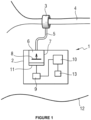
- FIG. 1 schematically illustrates the medical device 1 according to the invention according to an exemplary embodiment in which it corresponds to an artificial urinary sphincter intended to combat incontinence.
- the medical device 1 generally comprises a rigid housing 2 and a deformable element 3.
- the deformable element 3 is constituted by an inflatable occlusive cuff arranged around at least a portion of a natural conduit 4 of the human or animal body, the urethra in this case.
- the cuff is preferably made of biocompatible elastomer material, for example silicone.
- the housing 2 and the occlusive cuff 3 are connected by a tubular connection 5 and are in fluidic connection, that is to say that the medical device 1 is arranged to move fluid in variable volume from the housing to the cuff and vice versa. It is a hydraulically operated device.
- the housing 2 comprises a variable volume fluid reservoir 6.
- the reservoir 6, the tubular connection 4 and the occlusive sleeve 3 are all three fluidically connected so as to form a single fluid circuit.
- the reservoir 6 comprises a fixed part 7 and a movable part 8.
- the movable part 8 when moved, varies the volume of fluid in the reservoir to transfer it from the reservoir 6 to the occlusive cuff 3, which then inflates, increasing the pressure to occlude the duct.
- a movement of the movable part 8 in the opposite direction causes an increase in the volume of the reservoir, and therefore a transfer of fluid from the cuff 3 to the reservoir 6. This has the effect of releasing the pressure on the urethra and thus allowing urination.
- the movable part 8 of the tank 6 is mechanically coupled and driven by an actuator 9 to produce a linear movement relative to the fixed part 7 so as to adjust the volume of the tank.
- the actuator 9 may in particular comprise an electromagnetic motor and a reducer.
- the actuator is controlled by a control unit 10 described in detail below and powered by a rechargeable or non-rechargeable energy source (not shown).
- the energy source is outside the human body and transmits energy wirelessly to the medical device 1.
- Unit 10 is called a control unit but it is understood that it performs both command functions, control functions and calculation functions, as will appear in the following.
- the housing 2 also includes a sensor 11 capable of measuring or calculating the pressure in the fluid circuit.
- the sensor 11 measures either directly the pressure exerted or a force exerted and the control unit 10 then calculates the corresponding pressure.
- the sensor 11 is a force sensor arranged in the housing 2 and for example mechanically connected to the movable part 8 of the tank 6 to measure a tensile and/or compressive force in the direction of movement of the movable part of the tank.
- the force sensor is adapted to deflect under the application of a compressive or tensile force.
- This deformation can be measured for example by means of a strain gauge or strain gauge, and the applied force is determined from the deformation thus measured.
- the control unit 10 can then deduce the corresponding pressure therefrom, the force being the product of the pressure by the surface area.
- the senor 11 is mechanically linked to the actuator, itself mechanically coupled with the mobile part 8 of the tank 6, in particular in a fixed manner, so as to measure or calculate the pressure in the fluid circuit.
- the housing 2 of the medical device 1 may also include a position or posture sensor 13 connected to the control unit 10 for detecting the position or posture and/or the change in position or posture of a part of the human or animal body or of the entire body.
- This posture sensor 13 is for example in the form of an accelerometer, in particular an accelerometer arranged to calculate linear accelerations along three orthogonal axes, a gyroscope and/or an inclinometer.
- the reservoir 6 with its fixed part 7 and its movable part 8, the actuator 9, the control unit 10, the sensor 11 and the sensor 13 are all arranged in the housing 2 of the medical device 1.
- the medical device 1 including the housing 2, the cuff 3 and the tubular connection 5 are implanted in the human or animal body which is symbolized by the line 12 representing the skin of the body on the figure 1 .
- the implanted medical device 1 can be controlled remotely by the patient by means of a wireless control system not implanted in the human or animal body of the remote control type.
- the remote control system communicates with the medical device via radiofrequency waves or electromagnetic induction.
- This communication may be intended to control the operation of the implanted device, for example to activate or deactivate it, open or close the occlusive cuff, configure the internal parameters of the medical device or to obtain information from the device, for example to know the status of the device or to obtain patient parameters measured by sensors implanted with the device.
- the medical device is equipped with another sensor capable of detecting a mechanical action exerted on the body by the patient.
- This mechanical action may be in the form of tapping of a certain duration and frequency representing a code corresponding to a command.
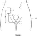
- FIG. 2 a human body 12 is illustrated in a standing position seen from the front with the medical device 1 according to the invention implanted.
- the housing 2 is implanted in the patient's abdomen while the occlusive cuff 3 in the case of the artificial sphincter is arranged around the urethra well below the housing. They are connected by means of the tubular connection 5.
- the housing 2 and the cuff 3 are therefore implanted at a distance from each other in the human body 12, and in particular at a different height when the patient is standing.
- H will be the height difference between the housing 2 and the cuff in the standing position, in other words this corresponds to the distance between the housing 2 and the cuff 3 in the vertical direction (direction of gravity) when the patient is in the standing position.
- the distance H is preferably at least 10 cm, more preferably a distance of at least 20 cm.
- This height difference causes a pressure difference between the pressure in housing 2 and the pressure in sleeve 3. This hydrostatic phenomenon is called a “water column”.
- the housing 2 and the cuff 3 are therefore implanted at a distance from each other in a direction substantially equivalent to a longitudinal direction of said body.
- This particular positioning induces a change in direction of the axis formed by the housing and the cuff during a change in posture of the body, in particular when changing from a standing to a lying position.
- the housing 2 and the cuff 3 are shown implanted at a distance from each other in the human body 12, with a height difference H when the patient is standing.
- the housing 2 and the cuff 3 are shown also implanted at a distance from each other in the human body 12, but this time with a height difference h when the patient is in the supine position.
- the height difference H in the patient's standing position is different from the height difference h in the supine position. Furthermore, in the case of the particular implantation of the medical device 1 to combat urinary incontinence, the height difference H in the standing position is greater than the height difference h in the supine position.
- the pressure in the occlusive sleeve 3 is therefore substantially equal to the pressure measured by the sensor 11 in the tank 6 plus the pressure corresponding to the water column H which is above the sleeve 3 and which therefore applies a corresponding pressure.
- the pressure in the occlusive sleeve 3 is substantially equal to the pressure measured by the sensor 11 in the tank 6 plus the pressure corresponding to the water column h which is above the sleeve 3.
- the pressure in the cuff 3 is substantially the same in the standing position and in the supine position, while the pressure in the reservoir 6 measured by the sensor 11 is different in the two positions.
- this effect is therefore taken advantage of to detect a posture and/or a change in posture of the body by means of measuring or calculating the pressure exerted in the reservoir 6 as will be explained in more detail below.
- the regulating balloon being flexible and deformable, there is a direct transmission of the pressure exerted by the water column to the occlusive cuff.
- the pressure exerted by the cuff which varies according to the position while the pressure in the regulating balloon is the same in the standing position and in the supine position.
- the detection method according to the invention provides for per-operative steps, implantation steps and post-operative steps.
- the per-operative step 20 consists of providing the medical device 1 comprising the housing 2, the deformable element 3 and the tubular connection 5, with inside the housing 2, the reservoir 6 equipped with a fixed part 7 and a mobile part 8, an actuator 9, a control unit 10, a sensor 11 capable of measuring or calculating the pressure in the reservoir 6 and the posture sensor 13 as described previously.
- step 21 during the operation, the surgeon implants this medical device 1 in order to obtain the configuration illustrated in the figure 2 with the housing 2 implanted in the patient's abdomen, the occlusive cuff 3 distant from the housing 3 and arranged around the urethra 4.
- the surgeon connects the housing 2 to the occlusive cuff 3 by means of the tubular connection 5 to create the fluid circuit.
- a device purge step is also planned (not detailed here) in order to evacuate the air and fill the device with fluid.
- the medical device can preferably be configured post-operatively.
- the following steps therefore describe the configuration of the medical device 1 to detect a posture and/or a change in posture of the body based on a variation in the pressure measured or calculated by the sensor 11.
- step 23 a calibration of the device 1 is carried out.
- this step may consist of asking the patient to take different and known postures such as going from the standing position to the supine position.
- the pressures measured by the sensor 11 are recorded in a table in the memory of the control unit 10 in correspondence with the positions, for example standing or lying down, or intermediate positions.
- thresholds can be defined from which the patient is considered to be in a specific position, for example lying down or standing.
- Calibration step 23 can be performed once or multiple times over time to refine measurements and make detection more robust.
- the sensor 11 measures the pressure at regular time intervals, preferably frequent to be more responsive to the posture change detections or to detect rapid posture changes. For example, pressure is measured every 200 milliseconds.
- step 25 the current pressure value is compared to the previous pressure value and to the values recorded during calibration step 23 to detect a change in posture and therefore a new posture in step 26.
- control unit 10 is arranged to repeat steps 24, 25 and 26 at regular and frequent time intervals to detect changes in posture.
- the measured values can be used in addition to the pressure values for posture detection.
- This posture sensor 13 for example a three-axis accelerometer, also requires calibration in step 23 to allow the accelerometer to be virtually aligned with a known reference frame.
- a virtual orientation allows the 3 axes of the accelerometer to be matched with the axes related to the body, i.e. the upper-lower axis, the posterior-anterior axis and the left-right axis.
- This virtual orientation is preferably obtained by calculating reference frame change matrices when the patient takes predetermined postures, the corresponding accelerations are then recorded and the reference frame change matrix is deduced from the fact that the only acceleration to which the body is subjected is gravitational acceleration.
- the medical device 1 is equipped with such a posture sensor 13, then it is provided in step 24 of the detection method according to the invention that the posture sensor 13 measures the posture at regular time intervals.
- the posture detection it is preferable for the posture detection to be frequent in order to be more responsive to changes. For example, the posture is measured every 200 milliseconds.
- step 25 the value corresponding to the posture is compared.
- the current acceleration values are compared to the previous acceleration values and to the values recorded during the calibration step 23 to detect a change in posture and therefore a new posture in step 26.
- a measurement of the pressure carried out by the pressure sensor 11, also calibrated in step 23, confirms or denies the detection of posture or change in posture by the posture sensor 13.
- the control unit 10 is also arranged to repeat steps 24, 25 and 26.
- a pressure measurement is carried out by the pressure sensor 11 allowing the current posture to be inferred.
- This inference is validated or invalidated by the comparison between the current pressure value and the pressure value linked to the position inferred during the calibration step 23.
- this embodiment with a posture sensor 13 available has the advantage of being able to save the overall energy used by the medical device when the pressure sensor 11 is only used to confirm the posture measured by the posture sensor 13 and only in certain cases, for example when the variation measured by the posture sensor is small.
- the present invention therefore allows for more robust and more reliable detection of posture or change of posture to enable the pressure exerted on the natural conduit by the deformable element to be adapted as best as possible and thus avoid over-stressing and damaging it.
- the invention is also applicable to other fields.
- medical devices that apply a specific therapy, such as a pacemaker or a neurostimulator.
- a pacemaker provides electrical impulses to stimulate the heart muscles, helping to speed up the heart rate when it is too slow.
- the invention allows the precise detection of body posture or a change in it, it is possible to detect that a patient is in a lying position because he has just had a fainting spell and that a specific therapy must be applied to modify his heart rate.
- Neurostimulators are implanted in the human body and connected to the spinal column. They are also configured to send electrical signals into the epidural space to relieve chronic pain.
- Neurostimulation works by interrupting pain signals between the spinal cord and the brain. The brain no longer receives these signals and the patient no longer feels pain.
- the deformable element is no longer arranged around a natural duct to be occluded. But in these applications, it takes the form of a balloon-type deformable element with no other function than that of being able to reproduce the water column phenomenon. It is therefore still arranged at the end of the tubular connection and still implanted in the body at a distance from the housing at a different height when the patient is standing. As previously described, it is possible to exploit a different pressure measurement depending on the position and therefore to detect a change in posture.
- the other elements of the medical device are similar and have a similar operation to what has been described previously.
Landscapes
- Health & Medical Sciences (AREA)
- Urology & Nephrology (AREA)
- Engineering & Computer Science (AREA)
- Animal Behavior & Ethology (AREA)
- Public Health (AREA)
- Veterinary Medicine (AREA)
- Biomedical Technology (AREA)
- Heart & Thoracic Surgery (AREA)
- Vascular Medicine (AREA)
- Life Sciences & Earth Sciences (AREA)
- General Health & Medical Sciences (AREA)
- Cardiology (AREA)
- Transplantation (AREA)
- Oral & Maxillofacial Surgery (AREA)
- Environmental & Geological Engineering (AREA)
- Nursing (AREA)
- Orthopedic Medicine & Surgery (AREA)
- Prostheses (AREA)
- Measurement Of Length, Angles, Or The Like Using Electric Or Magnetic Means (AREA)
- Measuring And Recording Apparatus For Diagnosis (AREA)
Claims (24)
- Medizinische Vorrichtung (1), die für eine Implantation in einen Körper eines Menschen oder eines Tieres (12) eingerichtet ist, umfassend ein Gehäuse (2), mindestens ein verformbares Element (3), eine Schlauchverbindung (5), die eine Fluidverbindung zwischen dem Gehäuse (2) und dem verformbaren Element (3) sichert, um einen Fluidkreis zu bilden, und mindestens einen Sensor (11), der imstande ist, einen Druck in dem Fluidkreis zu messen oder zu berechnen, wobei das Gehäuse (2) und das verformbare Element (3) dafür geeignet sind, voneinander beabstandet in den Körper eines Menschen oder eines Tieres implantiert zu werden, wobei die medizinische Vorrichtung (1) dadurch gekennzeichnet ist, dass sie ausgelegt ist, um eine Position und/oder einen Positionswechsel mindestens eines Teils des Körpers in Abhängigkeit von einer Veränderung des von dem Sensor gemessenen oder berechneten Drucks zu ermitteln.
- Medizinische Vorrichtung nach Anspruch 1, wobei das Gehäuse (2) starr ist und mit einem Ende der Schlauchverbindung (5) hermetisch verbunden ist.
- Medizinische Vorrichtung nach einem der vorangehenden Ansprüche, wobei das verformbare Element (3) aufblasbar ist.
- Medizinische Vorrichtung nach einem der vorangehenden Ansprüche, wobei der Sensor (11) im Inneren des Gehäuses (2) angeordnet und geeignet ist, den Druck in dem verformbaren Element (3) zu messen oder zu berechnen.
- Medizinische Vorrichtung nach dem vorangehenden Anspruch, wobei das Gehäuse (2) einen Fluidbehälter (6) umfasst, der einen beweglichen Teil (8) und einen Aktuator (9) des beweglichen Teils einschließt, um ein Volumen des Behälters zu verändern, wobei der Sensor (11), der geeigntet ist, den Druck zu messen oder zu berechnen, mit dem beweglichen Teil (8) und/oder mit dem Aktuator (9), mechanisch verbunden, insbesondere starr verbunden, ist.
- Medizinische Vorrichtung nach einem der vorangehenden Ansprüche, wobei das Gehäuse (2) und das verformbare Element (3) geeignet sind, in den Körper eines Menschen oder eines Tieres beabstandet voneinander implantiert zu werden entlang einer Richtung, die sich bei einem Positionswechsel von mindestens einem Teil des Körpers ändert, insbesondere bei einem Wechseln aus einer aufrechten Position in eine liegende Position.
- Medizinische Vorrichtung nach vorangehendem Anspruch, wobei das Gehäuse (2) und das verformbare Element (3) geeignet sind in den Körper eines Menschen oder eines Tieres beabstandet voneinander implantiert zu werden entlang einer Richtung, die näherungsweise äquivalent zu einer Längsrichtung des Körpers ist.
- Medizinische Vorrichtung nach einem der vorangehenden Ansprüche, wobei das Gehäuse (2) und das verformbare Element (3) geeignet sind, in den Körper eines Menschen oder eines Tieres beabstandet voneinander in einem Abstand von mindestens 5 cm, bevorzugterweise in einem Abstand von mindestens 10 cm, am meisten bevorzugt in einem Abstand von mindestens 20 cm implantiert zu werden.
- Medizinische Vorrichtung nach einem der vorangehenden Ansprüche, wobei die Vorrichtung (1) einen Positionssensor (13) mindestens eines Teils des Körpers eines Menschen oder eines Tieres umfasst.
- Medizinische Vorrichtung nach einem der Ansprüche 1 bis 8, wobei die Vorrichtung einen Positionssensor (13) mindestens eines Teils des Körpers eines Menschen oder eines Tieres umfasst, wobei die Vorrichtung dazu ausgelegt ist, die Position und/oder den Positionswechsel mindestens eines Teils des Körpers ausgehend von einer Messung oder einer Berechnung eines Drucks durch den Sensor (11), der imstande ist, den Druck im Fluidkreis zu messen oder zu berechnen, zu ermitteln und die Position und/oder den Positionswechsel ausgehend von einer Messung des Positionssensors (13) zu bestätigen.
- Medizinische Vorrichtung nach einem der Ansprüche 1 bis 8, wobei die Vorrichtung einen Positionssensor (13) mindestens eines Teils des Körpers eines Menschen oder eines Tieres umfasst, wobei die Vorrichtung dazu ausgelegt ist, die Position und/oder den Positionswechsel mindestens eines Teils des Körpers durch den Positionssensor (13) zu ermitteln und die Position und/oder den Positionswechsel ausgehend von einer Messung oder einer Berechnung des Drucks im Fluidkreis durch den Sensor (11), der geeignet ist, den Druck zu messen oder zu berechnen, zu bestätigen.
- Medizinische Vorrichtung nach einem der Ansprüche 9 bis 11, wobei der Positionssensor (13) ausgewählt ist aus: einem Beschleunigungsmesser, insbesondere einem Beschleunigungsmesser, der eingerichtet ist, um die linearen Beschleunigungen in drei orthogonalen Achsen zu berechnen, einem Gyroskop und/oder einem Neigungsmesser.
- Medizinische Vorrichtung nach einem der vorangehenden Ansprüche, wobei die Vorrichtung eine Steuereinheit (10) umfasst, die dazu ausgelegt ist, mindestens eine der folgenden Operationen durchzuführen:- Messen oder Berechnen eines Drucks mittels des Sensors, der imstande ist, einen Druck zu messen oder zu berechnen,- Ermitteln einer Position oder eines Positionswechsel mindestens eines Teils des Körpers in Abhängigkeit von einem Positionssensor mindestens eines Teils des Körpers eines Menschen oder eines Tieres und/oder dem Sensor, der imstande ist, den Druck zu messen oder zu berechnen.
- Medizinische Vorrichtung nach Anspruch 13 in Kombination mit Anspruch 5, wobei die Steuereinheit (10) dazu ausgelegt ist, den Aktuator zu steuern, um den beweglichen Teil des Behälters zu verlagern und das Volumen des Behälters zu verändern.
- Medizinische Vorrichtung nach einem der vorangehenden Ansprüche, wobei das verformbare Element (3) eine Verschlussmanschette ist, die eingerichtet ist, um einen natürlichen Leitungskanal (4) des Körpers eines Menschen oder eines Tieres zu verschließen.
- Medizinische Vorrichtung nach einem der Ansprüche 1 bis 15, wobei die Vorrichtung dazu ausgelegt ist, in den Körper eines Menschen oder eines Tieres implantiert zu sein, um einen natürlichen Leitungskanal (4) des Körpers eines Menschen oder eines Tiers zu verschließen, zu dem mindestens gehört: ein Harnleiter, ein Magenkanal, ein Kolon oder ein Rektum.
- Medizinische Vorrichtung nach einem der Ansprüche 1 bis 14, wobei die Vorrichtung dazu ausgelegt ist, als Herzstimulator oder als Neurostimulator zu wirken.
- Methode zur Ermittlung einer Position und/oder eines Positionswechsels mindestens eines Teils eines Körpers eines Menschen oder eines Tieres, wobei der Körper eine medizinische Vorrichtung (1) umfasst, die ein Gehäuse (2), mindestens ein verformbares Element (3), eine Schlauchverbindung (11), die eine Fluidverbindung zwischen dem Gehäuse (2) und dem verformbaren Element (3) sichert um einen Fluidkreis zu bilden, und mindestens einen Sensor (11), der imstande ist, einen Druck in dem Fluidkreis zu messen oder zu berechnen, umfasst, wobei das Gehäuse (2) und das verformbare Element (3) voneinander beabstandet angeordnet sind, wobei eine Position und/oder ein Positionswechsel mindestens eines Teils des Körpers in Abhängigkeit von einer Schwankung des von dem Sensor (11), der geeignet ist, einen Druck zu messen oder zu berechnen, gemessenen oder berechneten Druck ermittelt wird.
- Ermittlungsmethode nach vorangehendem Anspruch, wobei das Gehäuse (2) und das verformbare Element (3; 31; 41) in einer Richtung voneinander beabstandet sind, die sich bei einem Positionswechsel mindestens eines Teils des Körpers, insbesondere bei einem Wechsel aus einer aufrechten Position in eine liegende, ändert.
- Ermittlungsmethode nach vorangehendem Anspruch, wobei das Gehäuse (2) und das verformbare Element (3; 31; 41) in einer Richtung voneinander beabstandet sind, die näherungsweise einer Längsrichtung des Körpers äquivalent ist.
- Ermittlungsmethode nach einem der Ansprüche 18 bis 20, wobei die medizinische Vorrichtung eine Steuereinheit (10) umfasst, die mindestens eine der folgenden Operationen durchführt:- Messen oder Berechnen eines Drucks mittels des Sensors (11), der geeignet ist, einen Druck zu messen oder zu berechnen,- Ermitteln einer Position und/oder eines Positionswechsel mindestens eines Teils des Körpers in Abhängigkeit von einem Positionssensor (13) und/oder dem Sensor (11), der geeignet ist, den Druck zu messen oder zu berechnen.
- Ermittlungsmethode nach Anspruch 21, wobei die Steuereinheit (10) dazu ausgelegt ist, einen Aktuator (9) zu steuern, um einen beweglichen Teil (8) eines Behälters (6) zu verlagern und das Volumen des Behälters zu verändern.
- Ermittlungsmethode nach einem der Ansprüche 18 bis 22, wobei ein Positionssensor (13) kalibriert wird, der geeignet ist, eine Position und/oder einen Positionswechsel mindestens eines Teils des Körpers mittels des Sensors (11) zu ermitteln, der geeignet ist, einen Druck zu messen oder zu berechnen.
- Ermittlungsmethode nach einem der Ansprüche 18 bis 23, wobei das verformbare Element (3) aufblasbar ist und aus einer Verschlussmanschette ausgewählt ist, die eingerichtet ist, um einen natürlichen Leitungskanal des Körpers eines Menschen oder eines Tieres zu verschließen.
Applications Claiming Priority (2)
| Application Number | Priority Date | Filing Date | Title |
|---|---|---|---|
| FR2006429A FR3111539B1 (fr) | 2020-06-19 | 2020-06-19 | Dispositif medical et methode de detection d’un changement de position |
| PCT/FR2021/051086 WO2021255388A1 (fr) | 2020-06-19 | 2021-06-17 | Dispositif medical et methode de detection d'un changement de position |
Publications (3)
| Publication Number | Publication Date |
|---|---|
| EP4167902A1 EP4167902A1 (de) | 2023-04-26 |
| EP4167902C0 EP4167902C0 (de) | 2024-08-14 |
| EP4167902B1 true EP4167902B1 (de) | 2024-08-14 |
Family
ID=74125247
Family Applications (1)
| Application Number | Title | Priority Date | Filing Date |
|---|---|---|---|
| EP21740122.3A Active EP4167902B1 (de) | 2020-06-19 | 2021-06-17 | Medizinische vorrichtung und verfahren zur erkennung einer positionsänderung |
Country Status (5)
| Country | Link |
|---|---|
| US (1) | US20230320830A1 (de) |
| EP (1) | EP4167902B1 (de) |
| ES (1) | ES2992507T3 (de) |
| FR (1) | FR3111539B1 (de) |
| WO (1) | WO2021255388A1 (de) |
Families Citing this family (4)
| Publication number | Priority date | Publication date | Assignee | Title |
|---|---|---|---|---|
| IT202000015322A1 (it) * | 2020-06-25 | 2021-12-25 | Io Surgical Res S R L | Apparato di rilevazione e tracciamento della postura e/o della deformazione di un organo corporeo |
| EP4486248A1 (de) * | 2022-02-28 | 2025-01-08 | Boston Scientific Scimed Inc. | Elektronische pumpenanordnung und drucksteuerung für eine implantierbare vorrichtung |
| US20230270981A1 (en) * | 2022-02-28 | 2023-08-31 | Boston Scientific Scimed, Inc. | Electronic pump assembly and pressure control for an implantable device |
| FR3136364A1 (fr) | 2022-06-09 | 2023-12-15 | Uromems | Procédé d’estimation d’une valeur représentative d’une pression de fluide dans un élément gonflable d’un dispositif médical implantable |
Citations (1)
| Publication number | Priority date | Publication date | Assignee | Title |
|---|---|---|---|---|
| EP3223748B1 (de) * | 2014-11-25 | 2018-09-12 | Uromems | Implantierbares okklusionssystem |
Family Cites Families (19)
| Publication number | Priority date | Publication date | Assignee | Title |
|---|---|---|---|---|
| US6482145B1 (en) * | 2000-02-14 | 2002-11-19 | Obtech Medical Ag | Hydraulic anal incontinence treatment |
| DE60110392T2 (de) * | 2000-02-14 | 2006-03-09 | Potencia Medical Ag | Hydraulisches gerät zur behandlung von harninkontinenz |
| US8007429B2 (en) * | 2007-07-05 | 2011-08-30 | Gt Urological, Llc | Vessel occlusive device and method of occluding a vessel |
| FR2920087B1 (fr) * | 2007-08-24 | 2009-10-23 | Univ Grenoble 1 | Dispositif de prevention de fuites urinaires |
| US8696543B2 (en) * | 2007-10-11 | 2014-04-15 | Kirk Promotion Ltd. | Method for controlling flow of intestinal contents in a patient's intestines |
| US9439745B2 (en) * | 2007-10-11 | 2016-09-13 | Peter Forsell | Method for controlling flow of intestinal contents in a patient's intestines |
| EP3868335B1 (de) * | 2007-10-11 | 2024-06-12 | Implantica Patent Ltd. | Vorrichtung zur steuerung der strömung in einem körperorgan |
| US10307597B2 (en) * | 2007-10-11 | 2019-06-04 | Peter Forsell | Method for controlling flow of urine in a patient's urethra, ureter, renal pelvis or bladder |
| US20250032779A1 (en) * | 2008-10-10 | 2025-01-30 | Peter Forsell | Apparatus for influencing a flow in a bodily organ |
| US20230113368A1 (en) * | 2009-06-17 | 2023-04-13 | Peter Forsell | Surgical method |
| CN104220025B (zh) * | 2012-04-16 | 2017-03-22 | Gt泌尿学公司 | 液压尿道闭合装置 |
| FR3001631B1 (fr) * | 2013-02-01 | 2015-02-06 | Uromems | Systeme de controle d'un sphincter artificiel implantable dans le corps humain ou animal |
| CN105228563B (zh) * | 2013-03-15 | 2019-08-30 | 伊姆普兰蒂卡专利有限公司 | 约束设备 |
| FR3005847B1 (fr) * | 2013-05-21 | 2015-05-08 | Uromems | Procede et dispositif de detection d'une fuite lente dans un systeme occlusif hydraulique implantable |
| FR3005846B1 (fr) * | 2013-05-21 | 2018-03-23 | Uromems | Procede et dispositif de detection de l'atrophie d'un conduit naturel entoure d'un systeme d'occlusion |
| CN105530890A (zh) * | 2013-08-06 | 2016-04-27 | Gt泌尿学公司 | 液压尿道闭合装置 |
| FR3104405B1 (fr) * | 2019-12-16 | 2022-09-02 | Uromems | Accessoire pour l’implantation d’un dispositif médical configuré pour obturer un conduit anatomique |
| AT523787A1 (de) * | 2020-04-23 | 2021-11-15 | Ami Agency Medical Innovations Gmbh | Einrichtung umfassend einen Flüssigkeitsballon |
| AT523786A1 (de) * | 2020-04-23 | 2021-11-15 | Ami Agency Medical Innovations Gmbh | Verfahren zum Einstellen eines Befüllungszustandes eines Flüssigkeitsballons |
-
2020
- 2020-06-19 FR FR2006429A patent/FR3111539B1/fr active Active
-
2021
- 2021-06-17 EP EP21740122.3A patent/EP4167902B1/de active Active
- 2021-06-17 WO PCT/FR2021/051086 patent/WO2021255388A1/fr not_active Ceased
- 2021-06-17 US US17/928,440 patent/US20230320830A1/en active Pending
- 2021-06-17 ES ES21740122T patent/ES2992507T3/es active Active
Patent Citations (1)
| Publication number | Priority date | Publication date | Assignee | Title |
|---|---|---|---|---|
| EP3223748B1 (de) * | 2014-11-25 | 2018-09-12 | Uromems | Implantierbares okklusionssystem |
Also Published As
| Publication number | Publication date |
|---|---|
| US20230320830A1 (en) | 2023-10-12 |
| EP4167902C0 (de) | 2024-08-14 |
| ES2992507T3 (es) | 2024-12-13 |
| FR3111539B1 (fr) | 2022-10-14 |
| EP4167902A1 (de) | 2023-04-26 |
| WO2021255388A1 (fr) | 2021-12-23 |
| FR3111539A1 (fr) | 2021-12-24 |
Similar Documents
| Publication | Publication Date | Title |
|---|---|---|
| EP4167902B1 (de) | Medizinische vorrichtung und verfahren zur erkennung einer positionsänderung | |
| EP1317230B1 (de) | Vorrichtung zur aufblasregelung einer prosthetischen hülle | |
| EP1531771B1 (de) | Vorrichtung zum aufbringen von kontrollierter und anpassbarer kompression auf eine gliedmasse | |
| EP0820731B1 (de) | Skelettimplantat | |
| CN113271891A (zh) | 包括用于可膨胀植入件的液压加压的电子动力泵和阀系统的可植入装置 | |
| US20230157604A1 (en) | Apparatus, systems and methods for sensing bladder fullness | |
| CN112055575A (zh) | 用于可膨胀阴茎假体的多泵系统 | |
| FR2472376A1 (fr) | Prothese penienne destinee a pallier l'impuissance erectile masculine | |
| FR2930714A1 (fr) | Dispositif et procede de mesures et de controle de la rigidite d'un penis | |
| EP3277242A1 (de) | Vorrichtung zum antrieb der unteren gliedmassen einer person mit dorsalem oder partiellem dekubitus in kombination mit antrieb zum gehen in vertikaler position | |
| EP2950746B1 (de) | System zur erkennung einer endourethralen vorrichtung für einen in den körper eines menschen oder eine tieres implantierbaren künstlichen schliessmuskel | |
| EP4259038B1 (de) | Implantierbare medizinische vorrichtung | |
| EP0716837A2 (de) | Kavernöses Extensionsimplantat | |
| AU2023236702B2 (en) | Atrophy detection for tissue occluded by implantable inflation devices | |
| US20230293073A1 (en) | Atrophy detection for tissue occluded by implantable inflation devices | |
| JP7814538B2 (ja) | 埋め込み可能膨張デバイスによって閉塞された組織に対する萎縮検出 | |
| KR20240136431A (ko) | 팽창형 부재를 크기 조절하기 위한 이식 가능한 디바이스 | |
| CA3257628A1 (fr) | Implantable medical device | |
| WO2024173823A3 (en) | Baroreflex gauge and mapping device and methods of use | |
| CN118922150A (zh) | 用于由可植入式膨胀装置闭塞的组织的萎缩检测 |
Legal Events
| Date | Code | Title | Description |
|---|---|---|---|
| STAA | Information on the status of an ep patent application or granted ep patent |
Free format text: STATUS: UNKNOWN |
|
| STAA | Information on the status of an ep patent application or granted ep patent |
Free format text: STATUS: THE INTERNATIONAL PUBLICATION HAS BEEN MADE |
|
| PUAI | Public reference made under article 153(3) epc to a published international application that has entered the european phase |
Free format text: ORIGINAL CODE: 0009012 |
|
| STAA | Information on the status of an ep patent application or granted ep patent |
Free format text: STATUS: REQUEST FOR EXAMINATION WAS MADE |
|
| 17P | Request for examination filed |
Effective date: 20230106 |
|
| AK | Designated contracting states |
Kind code of ref document: A1 Designated state(s): AL AT BE BG CH CY CZ DE DK EE ES FI FR GB GR HR HU IE IS IT LI LT LU LV MC MK MT NL NO PL PT RO RS SE SI SK SM TR |
|
| DAV | Request for validation of the european patent (deleted) | ||
| DAX | Request for extension of the european patent (deleted) | ||
| GRAP | Despatch of communication of intention to grant a patent |
Free format text: ORIGINAL CODE: EPIDOSNIGR1 |
|
| STAA | Information on the status of an ep patent application or granted ep patent |
Free format text: STATUS: GRANT OF PATENT IS INTENDED |
|
| INTG | Intention to grant announced |
Effective date: 20231017 |
|
| GRAJ | Information related to disapproval of communication of intention to grant by the applicant or resumption of examination proceedings by the epo deleted |
Free format text: ORIGINAL CODE: EPIDOSDIGR1 |
|
| STAA | Information on the status of an ep patent application or granted ep patent |
Free format text: STATUS: REQUEST FOR EXAMINATION WAS MADE |
|
| INTC | Intention to grant announced (deleted) | ||
| GRAP | Despatch of communication of intention to grant a patent |
Free format text: ORIGINAL CODE: EPIDOSNIGR1 |
|
| STAA | Information on the status of an ep patent application or granted ep patent |
Free format text: STATUS: GRANT OF PATENT IS INTENDED |
|
| INTG | Intention to grant announced |
Effective date: 20240322 |
|
| GRAS | Grant fee paid |
Free format text: ORIGINAL CODE: EPIDOSNIGR3 |
|
| GRAA | (expected) grant |
Free format text: ORIGINAL CODE: 0009210 |
|
| STAA | Information on the status of an ep patent application or granted ep patent |
Free format text: STATUS: THE PATENT HAS BEEN GRANTED |
|
| AK | Designated contracting states |
Kind code of ref document: B1 Designated state(s): AL AT BE BG CH CY CZ DE DK EE ES FI FR GB GR HR HU IE IS IT LI LT LU LV MC MK MT NL NO PL PT RO RS SE SI SK SM TR |
|
| REG | Reference to a national code |
Ref country code: GB Ref legal event code: FG4D Free format text: NOT ENGLISH |
|
| REG | Reference to a national code |
Ref country code: CH Ref legal event code: EP |
|
| REG | Reference to a national code |
Ref country code: DE Ref legal event code: R096 Ref document number: 602021017255 Country of ref document: DE |
|
| REG | Reference to a national code |
Ref country code: IE Ref legal event code: FG4D Free format text: LANGUAGE OF EP DOCUMENT: FRENCH |
|
| U01 | Request for unitary effect filed |
Effective date: 20240912 |
|
| U07 | Unitary effect registered |
Designated state(s): AT BE BG DE DK EE FI FR IT LT LU LV MT NL PT RO SE SI Effective date: 20240927 |
|
| REG | Reference to a national code |
Ref country code: ES Ref legal event code: FG2A Ref document number: 2992507 Country of ref document: ES Kind code of ref document: T3 Effective date: 20241213 |
|
| PG25 | Lapsed in a contracting state [announced via postgrant information from national office to epo] |
Ref country code: NO Free format text: LAPSE BECAUSE OF FAILURE TO SUBMIT A TRANSLATION OF THE DESCRIPTION OR TO PAY THE FEE WITHIN THE PRESCRIBED TIME-LIMIT Effective date: 20241114 |
|
| PG25 | Lapsed in a contracting state [announced via postgrant information from national office to epo] |
Ref country code: GR Free format text: LAPSE BECAUSE OF FAILURE TO SUBMIT A TRANSLATION OF THE DESCRIPTION OR TO PAY THE FEE WITHIN THE PRESCRIBED TIME-LIMIT Effective date: 20241115 Ref country code: PL Free format text: LAPSE BECAUSE OF FAILURE TO SUBMIT A TRANSLATION OF THE DESCRIPTION OR TO PAY THE FEE WITHIN THE PRESCRIBED TIME-LIMIT Effective date: 20240814 |
|
| PG25 | Lapsed in a contracting state [announced via postgrant information from national office to epo] |
Ref country code: IS Free format text: LAPSE BECAUSE OF FAILURE TO SUBMIT A TRANSLATION OF THE DESCRIPTION OR TO PAY THE FEE WITHIN THE PRESCRIBED TIME-LIMIT Effective date: 20241214 |
|
| PG25 | Lapsed in a contracting state [announced via postgrant information from national office to epo] |
Ref country code: HR Free format text: LAPSE BECAUSE OF FAILURE TO SUBMIT A TRANSLATION OF THE DESCRIPTION OR TO PAY THE FEE WITHIN THE PRESCRIBED TIME-LIMIT Effective date: 20240814 |
|
| PG25 | Lapsed in a contracting state [announced via postgrant information from national office to epo] |
Ref country code: RS Free format text: LAPSE BECAUSE OF FAILURE TO SUBMIT A TRANSLATION OF THE DESCRIPTION OR TO PAY THE FEE WITHIN THE PRESCRIBED TIME-LIMIT Effective date: 20241114 |
|
| PG25 | Lapsed in a contracting state [announced via postgrant information from national office to epo] |
Ref country code: RS Free format text: LAPSE BECAUSE OF FAILURE TO SUBMIT A TRANSLATION OF THE DESCRIPTION OR TO PAY THE FEE WITHIN THE PRESCRIBED TIME-LIMIT Effective date: 20241114 Ref country code: PL Free format text: LAPSE BECAUSE OF FAILURE TO SUBMIT A TRANSLATION OF THE DESCRIPTION OR TO PAY THE FEE WITHIN THE PRESCRIBED TIME-LIMIT Effective date: 20240814 Ref country code: NO Free format text: LAPSE BECAUSE OF FAILURE TO SUBMIT A TRANSLATION OF THE DESCRIPTION OR TO PAY THE FEE WITHIN THE PRESCRIBED TIME-LIMIT Effective date: 20241114 Ref country code: IS Free format text: LAPSE BECAUSE OF FAILURE TO SUBMIT A TRANSLATION OF THE DESCRIPTION OR TO PAY THE FEE WITHIN THE PRESCRIBED TIME-LIMIT Effective date: 20241214 Ref country code: HR Free format text: LAPSE BECAUSE OF FAILURE TO SUBMIT A TRANSLATION OF THE DESCRIPTION OR TO PAY THE FEE WITHIN THE PRESCRIBED TIME-LIMIT Effective date: 20240814 Ref country code: GR Free format text: LAPSE BECAUSE OF FAILURE TO SUBMIT A TRANSLATION OF THE DESCRIPTION OR TO PAY THE FEE WITHIN THE PRESCRIBED TIME-LIMIT Effective date: 20241115 |
|
| PG25 | Lapsed in a contracting state [announced via postgrant information from national office to epo] |
Ref country code: SM Free format text: LAPSE BECAUSE OF FAILURE TO SUBMIT A TRANSLATION OF THE DESCRIPTION OR TO PAY THE FEE WITHIN THE PRESCRIBED TIME-LIMIT Effective date: 20240814 |
|
| PG25 | Lapsed in a contracting state [announced via postgrant information from national office to epo] |
Ref country code: CZ Free format text: LAPSE BECAUSE OF FAILURE TO SUBMIT A TRANSLATION OF THE DESCRIPTION OR TO PAY THE FEE WITHIN THE PRESCRIBED TIME-LIMIT Effective date: 20240814 |
|
| PG25 | Lapsed in a contracting state [announced via postgrant information from national office to epo] |
Ref country code: SK Free format text: LAPSE BECAUSE OF FAILURE TO SUBMIT A TRANSLATION OF THE DESCRIPTION OR TO PAY THE FEE WITHIN THE PRESCRIBED TIME-LIMIT Effective date: 20240814 |
|
| U20 | Renewal fee for the european patent with unitary effect paid |
Year of fee payment: 5 Effective date: 20250513 |
|
| PLBE | No opposition filed within time limit |
Free format text: ORIGINAL CODE: 0009261 |
|
| STAA | Information on the status of an ep patent application or granted ep patent |
Free format text: STATUS: NO OPPOSITION FILED WITHIN TIME LIMIT |
|
| PGFP | Annual fee paid to national office [announced via postgrant information from national office to epo] |
Ref country code: GB Payment date: 20250625 Year of fee payment: 5 |
|
| 26N | No opposition filed |
Effective date: 20250515 |
|
| PGFP | Annual fee paid to national office [announced via postgrant information from national office to epo] |
Ref country code: ES Payment date: 20250710 Year of fee payment: 5 |
|
| REG | Reference to a national code |
Ref country code: CH Ref legal event code: H13 Free format text: ST27 STATUS EVENT CODE: U-0-0-H10-H13 (AS PROVIDED BY THE NATIONAL OFFICE) Effective date: 20260127 |
|
| PG25 | Lapsed in a contracting state [announced via postgrant information from national office to epo] |
Ref country code: MC Free format text: LAPSE BECAUSE OF FAILURE TO SUBMIT A TRANSLATION OF THE DESCRIPTION OR TO PAY THE FEE WITHIN THE PRESCRIBED TIME-LIMIT Effective date: 20240814 |