EP4167839B1 - Contactless parameters measurement system and method - Google Patents
Contactless parameters measurement system and method Download PDFInfo
- Publication number
- EP4167839B1 EP4167839B1 EP21825038.9A EP21825038A EP4167839B1 EP 4167839 B1 EP4167839 B1 EP 4167839B1 EP 21825038 A EP21825038 A EP 21825038A EP 4167839 B1 EP4167839 B1 EP 4167839B1
- Authority
- EP
- European Patent Office
- Prior art keywords
- roi
- visible spectrum
- scene
- reference object
- processing circuitry
- Prior art date
- Legal status (The legal status is an assumption and is not a legal conclusion. Google has not performed a legal analysis and makes no representation as to the accuracy of the status listed.)
- Active
Links
Images



Classifications
-
- A—HUMAN NECESSITIES
- A61—MEDICAL OR VETERINARY SCIENCE; HYGIENE
- A61B—DIAGNOSIS; SURGERY; IDENTIFICATION
- A61B5/00—Measuring for diagnostic purposes; Identification of persons
- A61B5/0059—Measuring for diagnostic purposes; Identification of persons using light, e.g. diagnosis by transillumination, diascopy, fluorescence
- A61B5/0075—Measuring for diagnostic purposes; Identification of persons using light, e.g. diagnosis by transillumination, diascopy, fluorescence by spectroscopy, i.e. measuring spectra, e.g. Raman spectroscopy, infrared absorption spectroscopy
-
- A—HUMAN NECESSITIES
- A61—MEDICAL OR VETERINARY SCIENCE; HYGIENE
- A61B—DIAGNOSIS; SURGERY; IDENTIFICATION
- A61B5/00—Measuring for diagnostic purposes; Identification of persons
- A61B5/0002—Remote monitoring of patients using telemetry, e.g. transmission of vital signals via a communication network
- A61B5/0004—Remote monitoring of patients using telemetry, e.g. transmission of vital signals via a communication network characterised by the type of physiological signal transmitted
- A61B5/0008—Temperature signals
-
- A—HUMAN NECESSITIES
- A61—MEDICAL OR VETERINARY SCIENCE; HYGIENE
- A61B—DIAGNOSIS; SURGERY; IDENTIFICATION
- A61B5/00—Measuring for diagnostic purposes; Identification of persons
- A61B5/0059—Measuring for diagnostic purposes; Identification of persons using light, e.g. diagnosis by transillumination, diascopy, fluorescence
- A61B5/0077—Devices for viewing the surface of the body, e.g. camera, magnifying lens
-
- A—HUMAN NECESSITIES
- A61—MEDICAL OR VETERINARY SCIENCE; HYGIENE
- A61B—DIAGNOSIS; SURGERY; IDENTIFICATION
- A61B5/00—Measuring for diagnostic purposes; Identification of persons
- A61B5/01—Measuring temperature of body parts ; Diagnostic temperature sensing, e.g. for malignant or inflamed tissue
-
- A—HUMAN NECESSITIES
- A61—MEDICAL OR VETERINARY SCIENCE; HYGIENE
- A61B—DIAGNOSIS; SURGERY; IDENTIFICATION
- A61B5/00—Measuring for diagnostic purposes; Identification of persons
- A61B5/02—Detecting, measuring or recording for evaluating the cardiovascular system, e.g. pulse, heart rate, blood pressure or blood flow
- A61B5/0205—Simultaneously evaluating both cardiovascular conditions and different types of body conditions, e.g. heart and respiratory condition
- A61B5/02055—Simultaneously evaluating both cardiovascular condition and temperature
-
- A—HUMAN NECESSITIES
- A61—MEDICAL OR VETERINARY SCIENCE; HYGIENE
- A61B—DIAGNOSIS; SURGERY; IDENTIFICATION
- A61B5/00—Measuring for diagnostic purposes; Identification of persons
- A61B5/02—Detecting, measuring or recording for evaluating the cardiovascular system, e.g. pulse, heart rate, blood pressure or blood flow
- A61B5/024—Measuring pulse rate or heart rate
-
- A—HUMAN NECESSITIES
- A61—MEDICAL OR VETERINARY SCIENCE; HYGIENE
- A61B—DIAGNOSIS; SURGERY; IDENTIFICATION
- A61B5/00—Measuring for diagnostic purposes; Identification of persons
- A61B5/08—Measuring devices for evaluating the respiratory organs
- A61B5/0816—Measuring devices for examining respiratory frequency
-
- A—HUMAN NECESSITIES
- A61—MEDICAL OR VETERINARY SCIENCE; HYGIENE
- A61B—DIAGNOSIS; SURGERY; IDENTIFICATION
- A61B5/00—Measuring for diagnostic purposes; Identification of persons
- A61B5/08—Measuring devices for evaluating the respiratory organs
- A61B5/087—Measuring breath flow
- A61B5/0878—Measuring breath flow using temperature sensing means
-
- A—HUMAN NECESSITIES
- A61—MEDICAL OR VETERINARY SCIENCE; HYGIENE
- A61B—DIAGNOSIS; SURGERY; IDENTIFICATION
- A61B5/00—Measuring for diagnostic purposes; Identification of persons
- A61B5/103—Measuring devices for testing the shape, pattern, colour, size or movement of the body or parts thereof, for diagnostic purposes
- A61B5/11—Measuring movement of the entire body or parts thereof, e.g. head or hand tremor or mobility of a limb
- A61B5/1113—Local tracking of patients, e.g. in a hospital or private home
-
- A—HUMAN NECESSITIES
- A61—MEDICAL OR VETERINARY SCIENCE; HYGIENE
- A61B—DIAGNOSIS; SURGERY; IDENTIFICATION
- A61B5/00—Measuring for diagnostic purposes; Identification of persons
- A61B5/103—Measuring devices for testing the shape, pattern, colour, size or movement of the body or parts thereof, for diagnostic purposes
- A61B5/11—Measuring movement of the entire body or parts thereof, e.g. head or hand tremor or mobility of a limb
- A61B5/113—Measuring movement of the entire body or parts thereof, e.g. head or hand tremor or mobility of a limb occurring during breathing
-
- A—HUMAN NECESSITIES
- A61—MEDICAL OR VETERINARY SCIENCE; HYGIENE
- A61B—DIAGNOSIS; SURGERY; IDENTIFICATION
- A61B5/00—Measuring for diagnostic purposes; Identification of persons
- A61B5/74—Details of notification to user or communication with user or patient; User input means
- A61B5/746—Alarms related to a physiological condition, e.g. details of setting alarm thresholds or avoiding false alarms
-
- G—PHYSICS
- G01—MEASURING; TESTING
- G01J—MEASUREMENT OF INTENSITY, VELOCITY, SPECTRAL CONTENT, POLARISATION, PHASE OR PULSE CHARACTERISTICS OF INFRARED, VISIBLE OR ULTRAVIOLET LIGHT; COLORIMETRY; RADIATION PYROMETRY
- G01J5/00—Radiation pyrometry, e.g. infrared or optical thermometry
- G01J5/0022—Radiation pyrometry, e.g. infrared or optical thermometry for sensing the radiation of moving bodies
- G01J5/0025—Living bodies
-
- G—PHYSICS
- G01—MEASURING; TESTING
- G01J—MEASUREMENT OF INTENSITY, VELOCITY, SPECTRAL CONTENT, POLARISATION, PHASE OR PULSE CHARACTERISTICS OF INFRARED, VISIBLE OR ULTRAVIOLET LIGHT; COLORIMETRY; RADIATION PYROMETRY
- G01J5/00—Radiation pyrometry, e.g. infrared or optical thermometry
- G01J5/02—Constructional details
- G01J5/06—Arrangements for eliminating effects of disturbing radiation; Arrangements for compensating changes in sensitivity
- G01J5/064—Ambient temperature sensor; Housing temperature sensor; Constructional details thereof
-
- G—PHYSICS
- G01—MEASURING; TESTING
- G01J—MEASUREMENT OF INTENSITY, VELOCITY, SPECTRAL CONTENT, POLARISATION, PHASE OR PULSE CHARACTERISTICS OF INFRARED, VISIBLE OR ULTRAVIOLET LIGHT; COLORIMETRY; RADIATION PYROMETRY
- G01J5/00—Radiation pyrometry, e.g. infrared or optical thermometry
- G01J5/70—Passive compensation of pyrometer measurements, e.g. using ambient temperature sensing or sensing of temperature within housing
-
- G—PHYSICS
- G01—MEASURING; TESTING
- G01J—MEASUREMENT OF INTENSITY, VELOCITY, SPECTRAL CONTENT, POLARISATION, PHASE OR PULSE CHARACTERISTICS OF INFRARED, VISIBLE OR ULTRAVIOLET LIGHT; COLORIMETRY; RADIATION PYROMETRY
- G01J5/00—Radiation pyrometry, e.g. infrared or optical thermometry
- G01J5/80—Calibration
- G01J5/802—Calibration by correcting for emissivity
-
- G—PHYSICS
- G06—COMPUTING OR CALCULATING; COUNTING
- G06T—IMAGE DATA PROCESSING OR GENERATION, IN GENERAL
- G06T7/00—Image analysis
- G06T7/0002—Inspection of images, e.g. flaw detection
- G06T7/0012—Biomedical image inspection
-
- G—PHYSICS
- G06—COMPUTING OR CALCULATING; COUNTING
- G06T—IMAGE DATA PROCESSING OR GENERATION, IN GENERAL
- G06T7/00—Image analysis
- G06T7/20—Analysis of motion
-
- G—PHYSICS
- G06—COMPUTING OR CALCULATING; COUNTING
- G06T—IMAGE DATA PROCESSING OR GENERATION, IN GENERAL
- G06T7/00—Image analysis
- G06T7/30—Determination of transform parameters for the alignment of images, i.e. image registration
- G06T7/33—Determination of transform parameters for the alignment of images, i.e. image registration using feature-based methods
- G06T7/337—Determination of transform parameters for the alignment of images, i.e. image registration using feature-based methods involving reference images or patches
-
- G—PHYSICS
- G06—COMPUTING OR CALCULATING; COUNTING
- G06V—IMAGE OR VIDEO RECOGNITION OR UNDERSTANDING
- G06V10/00—Arrangements for image or video recognition or understanding
- G06V10/10—Image acquisition
- G06V10/12—Details of acquisition arrangements; Constructional details thereof
- G06V10/14—Optical characteristics of the device performing the acquisition or on the illumination arrangements
- G06V10/143—Sensing or illuminating at different wavelengths
-
- G—PHYSICS
- G06—COMPUTING OR CALCULATING; COUNTING
- G06V—IMAGE OR VIDEO RECOGNITION OR UNDERSTANDING
- G06V10/00—Arrangements for image or video recognition or understanding
- G06V10/10—Image acquisition
- G06V10/12—Details of acquisition arrangements; Constructional details thereof
- G06V10/14—Optical characteristics of the device performing the acquisition or on the illumination arrangements
- G06V10/147—Details of sensors, e.g. sensor lenses
-
- G—PHYSICS
- G06—COMPUTING OR CALCULATING; COUNTING
- G06V—IMAGE OR VIDEO RECOGNITION OR UNDERSTANDING
- G06V10/00—Arrangements for image or video recognition or understanding
- G06V10/20—Image preprocessing
- G06V10/22—Image preprocessing by selection of a specific region containing or referencing a pattern; Locating or processing of specific regions to guide the detection or recognition
-
- G—PHYSICS
- G06—COMPUTING OR CALCULATING; COUNTING
- G06V—IMAGE OR VIDEO RECOGNITION OR UNDERSTANDING
- G06V10/00—Arrangements for image or video recognition or understanding
- G06V10/20—Image preprocessing
- G06V10/25—Determination of region of interest [ROI] or a volume of interest [VOI]
-
- G—PHYSICS
- G06—COMPUTING OR CALCULATING; COUNTING
- G06V—IMAGE OR VIDEO RECOGNITION OR UNDERSTANDING
- G06V10/00—Arrangements for image or video recognition or understanding
- G06V10/70—Arrangements for image or video recognition or understanding using pattern recognition or machine learning
- G06V10/77—Processing image or video features in feature spaces; using data integration or data reduction, e.g. principal component analysis [PCA] or independent component analysis [ICA] or self-organising maps [SOM]; Blind source separation
- G06V10/80—Fusion, i.e. combining data from various sources at the sensor level, preprocessing level, feature extraction level or classification level
- G06V10/803—Fusion, i.e. combining data from various sources at the sensor level, preprocessing level, feature extraction level or classification level of input or preprocessed data
-
- G—PHYSICS
- G06—COMPUTING OR CALCULATING; COUNTING
- G06V—IMAGE OR VIDEO RECOGNITION OR UNDERSTANDING
- G06V20/00—Scenes; Scene-specific elements
- G06V20/50—Context or environment of the image
- G06V20/52—Surveillance or monitoring of activities, e.g. for recognising suspicious objects
-
- G—PHYSICS
- G06—COMPUTING OR CALCULATING; COUNTING
- G06V—IMAGE OR VIDEO RECOGNITION OR UNDERSTANDING
- G06V40/00—Recognition of biometric, human-related or animal-related patterns in image or video data
- G06V40/10—Human or animal bodies, e.g. vehicle occupants or pedestrians; Body parts, e.g. hands
- G06V40/103—Static body considered as a whole, e.g. static pedestrian or occupant recognition
-
- G—PHYSICS
- G06—COMPUTING OR CALCULATING; COUNTING
- G06V—IMAGE OR VIDEO RECOGNITION OR UNDERSTANDING
- G06V40/00—Recognition of biometric, human-related or animal-related patterns in image or video data
- G06V40/10—Human or animal bodies, e.g. vehicle occupants or pedestrians; Body parts, e.g. hands
- G06V40/16—Human faces, e.g. facial parts, sketches or expressions
- G06V40/168—Feature extraction; Face representation
- G06V40/171—Local features and components; Facial parts ; Occluding parts, e.g. glasses; Geometrical relationships
-
- A—HUMAN NECESSITIES
- A61—MEDICAL OR VETERINARY SCIENCE; HYGIENE
- A61B—DIAGNOSIS; SURGERY; IDENTIFICATION
- A61B2560/00—Constructional details of operational features of apparatus; Accessories for medical measuring apparatus
- A61B2560/02—Operational features
- A61B2560/0242—Operational features adapted to measure environmental factors, e.g. temperature, pollution
- A61B2560/0247—Operational features adapted to measure environmental factors, e.g. temperature, pollution for compensation or correction of the measured physiological value
- A61B2560/0252—Operational features adapted to measure environmental factors, e.g. temperature, pollution for compensation or correction of the measured physiological value using ambient temperature
-
- G—PHYSICS
- G01—MEASURING; TESTING
- G01J—MEASUREMENT OF INTENSITY, VELOCITY, SPECTRAL CONTENT, POLARISATION, PHASE OR PULSE CHARACTERISTICS OF INFRARED, VISIBLE OR ULTRAVIOLET LIGHT; COLORIMETRY; RADIATION PYROMETRY
- G01J5/00—Radiation pyrometry, e.g. infrared or optical thermometry
- G01J2005/0077—Imaging
-
- G—PHYSICS
- G06—COMPUTING OR CALCULATING; COUNTING
- G06T—IMAGE DATA PROCESSING OR GENERATION, IN GENERAL
- G06T2207/00—Indexing scheme for image analysis or image enhancement
- G06T2207/10—Image acquisition modality
- G06T2207/10024—Color image
-
- G—PHYSICS
- G06—COMPUTING OR CALCULATING; COUNTING
- G06T—IMAGE DATA PROCESSING OR GENERATION, IN GENERAL
- G06T2207/00—Indexing scheme for image analysis or image enhancement
- G06T2207/10—Image acquisition modality
- G06T2207/10028—Range image; Depth image; 3D point clouds
-
- G—PHYSICS
- G06—COMPUTING OR CALCULATING; COUNTING
- G06T—IMAGE DATA PROCESSING OR GENERATION, IN GENERAL
- G06T2207/00—Indexing scheme for image analysis or image enhancement
- G06T2207/10—Image acquisition modality
- G06T2207/10048—Infrared image
-
- G—PHYSICS
- G06—COMPUTING OR CALCULATING; COUNTING
- G06T—IMAGE DATA PROCESSING OR GENERATION, IN GENERAL
- G06T2207/00—Indexing scheme for image analysis or image enhancement
- G06T2207/30—Subject of image; Context of image processing
- G06T2207/30196—Human being; Person
- G06T2207/30201—Face
Definitions
- the invention relates to a system and method for usage of high accuracy contactless temperature measurement for determination of physiological body parameters.
- a physiological monitor includes imaging sensors (120, 122, 124, 126), one of which is a time-of-flight imaging sensor (122).
- the physiological monitor (100) also includes a processing device (130) to receive data streams from the imaging sensors (120, 122, 124, 126). The processing device (130) may then extract time parameter data from the data streams, identify a physiological parameter from the extracted parameter data, and provide an indication of the physiological parameter.
- MULTI-SPECTRAL FACIAL BIOMETRICS IN ACCESS CONTROL published on December, 2014 , discloses how facial biometrics, acquired using multi-spectral sensors, such as RGB, depth, and infrared, assist the data accumulation in the process of authorizing users of automated and semi-automated access systems.
- This data serves the purposes of person authentication, as well as facial temperature estimation.
- a tracking system comprising one or more cameras adapted to take images, one or more data processing units, said tracking system further comprising one or more output or display units, wherein said camera is adapted to observe a geographical area of interest, wherein said one or more data processing unit is configured to detect a moving entity in the area of interest, to identify a reference zone in at least some of said images, wherein said reference zone is on or associated with said moving entity, and to analyze the reference zone in order to determine at least one parameter associated with said moving entity.
- US Patent application No. 2019/0321719 published on October 24, 2019 , discloses apparatuses and techniques for radar-enabled sensor fusion.
- a radar field is provided and reflection signals that correspond to a target in the radar field are received.
- the reflection signals are transformed to provide radar data, from which a radar feature indicating a physical characteristic of the target is extracted.
- a sensor is activated to provide supplemental sensor data associated with the physical characteristic.
- the radar feature is then augmented with the supplemental sensor data to enhance the radar feature, such as by increasing an accuracy or resolution of the radar feature.
- a method for interacting with a user comprises predicting suggested action(s) for the user and displaying the action(s) via a display of the device. While the suggested action(s) are displayed, audio input comprising a command followed by a keyword is received from the user. The audio input is processed locally on the intelligent assistance device to (1) determine that the keyword follows the command and (2) recognize that the command applies to the suggested action(s). Based on determining that the keyword follows the command and recognizing that the command applies to the suggested action(s), a user selection of the suggested action(s) is established. Based on establishing the user selection, the one or more suggested actions are executed.
- US Patent application No. 2018/0143318 discloses a passive-tracking system is described herein.
- the system can include a visible-light sensor, a sound transducer, a thermal sensor, a time-of-flight (ToF) sensor, and a processor.
- the processor can receive visible-light frames from the visible-light sensor, sound frames from the sound transducer, thermal frames from the thermal sensor, and modulated-light frames from the ToF sensor.
- the processor based on data of the visible-light and temperature frames, can also determine that an object is a living being and can provide an X and Y position of the object.
- the processor based on data of the sound and positioning frames, can determine a Z position of the object.
- the X, Y, and Z positions may combine to form a three-dimensional (3D) position of the object.
- the processor can also passively track the object over time by selectively updating the 3D position of the object.
- Document US 2019/080431 A1 discloses an imaging system including a 3D image capture device, which is configured to capture a depth image of an object, and a thermal image capture device, which is configured to capture a thermal image of the object.
- the imaging system also includes a processing system, which is coupled with the 3D image capture device and the thermal image capture device.
- the processing system is configured to process the depth image and the thermal image to produce a thermal-depth fusion image by aligning the thermal image with the depth image, and assigning a thermal value derived from the thermal image to a plurality of points of the depth image.
- Document KR 2017 0050936 A1 relates to a dual camera-based body temperature monitoring system using a blackbody, capable of measuring the temperature of a person while recording an image of the measured person by simultaneously photographing the person with a thermo-graphic camera and a visible ray camera.
- Document KR 101 729 327 B1 relates to a body temperature tracking monitoring system using a dual camera that captures a person at the same time by using a thermal camera and a visible light camera, and measures a body temperature of a person and records an image of a person who has measured the same.
- Document US 2007/153871 A1 discloses a system for fast noncontact screening for fever human subjects by means of a thermal imaging camera.
- the camera is combined with a target gate that incorporates the reference blackbody targets and position detectors to identify the temperature scale and size of a subject.
- Document US 2015/009335 A1 relates to a method for enabling improved calibration of captured infrared data values by an IR imaging system in a thermography arrangement dependent on an infrared (IR) image depicting an observed real world scene, said IR image being captured by a thermography arrangement comprising said IR imaging system, wherein infrared (IR) image is related to temperature dependent on IR calibration parameters, the method comprising: capturing an IR image depicting the observed real world scene using the IR imaging system, determining that a predefined feature is represented by IR pixels in the IR image and obtaining a second subset of said IR pixels representing said predefined feature; and calibrating said IR imaging system based on the captured infrared data values associated with said second subset of said IR pixels and a predetermined temperature value associated to said predefined feature.
- IR infrared
- a system for measuring temperature of at least two subjects within a scene including a reference object, the reference object having an unknown emissivity and an ambient temperature, wherein the ambient temperature of the reference object is the scene ambient temperature
- the system comprising: a visible spectrum camera configured to acquire images of the scene comprising (a) at least a Region of Interest (RoI) of each of the subjects, and (b) the reference object; a thermal image sensor configured to acquire images of the scene comprising (a) at least the RoI of each of the subjects, and (b) the reference object; and a processing circuitry configured to: obtain (a) a visible spectrum image captured by the visible spectrum camera, and (b) a thermal image captured by the thermal image sensor, and (c) an indication of the scene ambient temperature within the scene; register the visible spectrum image and the thermal image onto a common coordinate system; identify (a) RoI pixels, on the common coordinate system, of the RoIs of the subjects within the visible spectrum image, and (
- the determination of the parameter correlated to the emissivity of the reference object is performed by analyzing the reference temperature and the indication of the scene ambient temperature at a plurality of point in time during a given time period.
- the system further comprising a three-dimensional (3D) camera capable of acquiring images of the scene comprising (a) at least a Region of Interest (RoI) of each of the subjects, and (b) the reference object, and wherein the processing circuitry is further configured to: obtain a depth image captured by the 3D camera; and utilize the depth image for the registration of the visible spectrum image and the thermal image onto the common coordinate system.
- 3D three-dimensional
- the correction of the RoI temperatures is also based on at least one of: (a) a distance of the respective subject from the thermal image sensor determined based on the analysis of the depth image, or (b) on ambient moisture level.
- the indication of the ambient moisture level of is obtained from a moisture measuring device.
- the indication of the scene ambient temperature is obtained from a thermometer measuring ambient temperature within the scene.
- the thermal image sensor is uncooled.
- the visible spectrum camera has a spatial resolution higher than 2mm/pixel.
- the thermal spectrum camera has a spatial resolution higher than 2mm/pixel.
- the subjects are living subjects.
- the RoI is a body part of a body of the subject.
- the subjects are animals and wherein the RoI is one or more of: a body part of a body of the respective animal subject, a face of the respective animal subject, a forehead of the respective animal subject, or a mouth of the respective animal subject.
- the animals are human beings.
- the subjects are plants and wherein the RoI is one or more of: a leaf of the respective plant subject, or a fruit of the respective plant subject.
- the subjects are machines and wherein the RoI is an engine of the respective machine subject.
- the reference object is diffusive and not specular.
- the processing circuitry is further configured to alert an operator of the system upon identifying subjects associated with corrected RoI temperatures exceeding a threshold.
- the reference object is made of material which temperature changes in a known manner according to changes to the scene ambient temperature.
- the RoI is an area affected by breathing of the respective subject and wherein the processing circuitry is further configured to:obtain (a) a first sequence of subsequent visible spectrum images captured by the visible spectrum camera subsequently to the visible spectrum image, and (b) a second sequence of subsequent thermal images captured by the thermal image sensor subsequently to the thermal image; register the subsequent visible spectrum images and the subsequent thermal images onto the common coordinate system; identify subsequent RoI pixels, on the common coordinate system, of the RoIs of the subjects within the subsequent visible spectrum images; track the subsequent RoI pixels within the subsequent thermal images of the second sequence utilizing the respective subsequent visible spectrum images of the first sequence; and determine a respiratory rate of the respective subject by analyzing the tracked subsequent RoI pixels.
- the RoI is a forehead of the respective subject and wherein the processing circuitry is further configured to: obtain a third sequence of subsequent visible spectrum images captured by the visible spectrum camera subsequently to the visible spectrum image; track the RoI within the subsequent visible spectrum images of the third sequence; and determine a pulse of the respective subject by analyzing changes of color within the RoI.
- the reference object includes one or more symbols visible to the visible spectrum camera or to the thermal image sensor and wherein the reference object pixels are identified using at least one of the symbols.
- the method comprising: obtaining, by a processing circuitry, (a) a visible spectrum image captured by a visible spectrum camera configured to acquire images of the scene comprising at least a Region of Interest (RoI) of each of the subjects, and the reference object, and (b) a thermal image captured by a thermal image sensor configured to acquire images of the scene comprising at least the RoI of each of the subjects, and the reference object, and (c) an indication of the scene ambient temperature within the scene; registering, by the processing circuitry, the visible spectrum image and the thermal image onto a common coordinate system; identifying, by the processing circuitry, (a) RoI pixels, on the common coordinate system, of the RoIs of the subjects within the visible spectrum image, and (b) reference object pixels,
- the determination of the parameter correlated to the emissivity of the reference object is performed by analyzing the reference temperature and the indication of the scene ambient temperature at a plurality of point in time during a given time period.
- the method further comprising: obtaining, by the processing circuitry, a depth image captured by a three-dimensional (3D) camera capable of acquiring images of the scene comprising (a) at least a Region of Interest (RoI) of each of the subjects, and (b) the reference object; and utilizing, by the processing circuitry, the depth image for the registration of the visible spectrum image and the thermal image onto the common coordinate system.
- a depth image captured by a three-dimensional (3D) camera capable of acquiring images of the scene comprising (a) at least a Region of Interest (RoI) of each of the subjects, and (b) the reference object
- RoI Region of Interest
- the correction of the RoI temperatures is also based on at least one of: (a) a distance of the respective subject from the thermal image sensor determined based on the analysis of the depth image, or (b) on ambient moisture level.
- the indication of the ambient moisture level of is obtained from a moisture measuring device.
- the indication of the scene ambient temperature is obtained from a thermometer measuring ambient temperature within the scene.
- the thermal image sensor is uncooled.
- the visible spectrum camera has a spatial resolution higher than 2mm/pixel.
- the thermal spectrum camera has a spatial resolution higher than 2mm/pixel.
- the subjects are living subjects.
- the RoI is a body part of a body of the subject.
- the subjects are animals and wherein the RoI is one or more of: a body part of a body of the respective animal subject, a face of the respective animal subject, a forehead of the respective animal subject, or a mouth of the respective animal subject.
- the animals are human beings.
- the subjects are plants and wherein the RoI is one or more of: a leaf of the respective plant subject, or a fruit of the respective plant subject.
- the subjects are machines and wherein the RoI is an engine of the respective machine subject.
- the reference object is diffusive and not specular.
- the method further comprising alerting, by the processing circuitry, an operator of the system upon identifying subjects associated with corrected RoI temperatures exceeding a threshold.
- the reference object is made of material which temperature changes in a known manner according to changes to the scene ambient temperature.
- the RoI is an area affected by breathing of the respective subject and wherein method further comprising: obtaining, by the processing circuitry, (a) a first sequence of subsequent visible spectrum images captured by the visible spectrum camera subsequently to the visible spectrum image, and (b) a second sequence of subsequent thermal images captured by the thermal image sensor subsequently to the thermal image; registering, by the processing circuitry, the subsequent visible spectrum images and the subsequent thermal images onto the common coordinate system; identifying, by the processing circuitry, subsequent RoI pixels, on the common coordinate system, of the RoIs of the subjects within the subsequent visible spectrum images; tracking, by the processing circuitry, the subsequent RoI pixels within the subsequent thermal images of the second sequence utilizing the respective subsequent visible spectrum images of the first sequence; and determining, by the processing circuitry, a respiratory rate of the respective subject by analyzing the tracked subsequent RoI pixels.
- the RoI is a forehead of the respective subject and wherein the method further comprising: obtaining, by the processing circuitry, a third sequence of subsequent visible spectrum images captured by the visible spectrum camera subsequently to the visible spectrum image; tracking, by the processing circuitry, the RoI within the subsequent visible spectrum images of the third sequence; and determining, by the processing circuitry, a pulse of the respective subject by analyzing changes of color within the RoI.
- the reference object includes one or more symbols visible to the visible spectrum camera or to the thermal image sensor and wherein the reference object pixels are identified using at least one of the symbols.
- a non-transitory computer readable storage medium having computer readable program code embodied therewith, the computer readable program code, executable by at least one processing circuitry of a computer to perform a method for measuring temperature of at least two subjects within a scene including a reference object, the reference object having an unknown emissivity and an ambient temperature, wherein the ambient temperature of the reference object is the scene ambient temperature, the method comprising: obtaining, by a processing circuitry, (a) a visible spectrum image captured by a visible spectrum camera configured to acquire images of the scene comprising at least a Region of Interest (RoI) of each of the subjects, and the reference object, and (b) a thermal image captured by a thermal image sensor configured to acquire images of the scene comprising at least the RoI of each of the subjects, and the reference object, and (c) an indication of the scene ambient temperature within the scene; registering, by the processing circuitry, the visible spectrum image and the thermal image onto a common coordinate
- DSP digital signal processor
- FPGA field programmable gate array
- ASIC application specific integrated circuit
- non-transitory is used herein to exclude transitory, propagating signals, but to otherwise include any volatile or non-volatile computer memory technology suitable to the application.
- the phrase “for example,” “such as”, “for instance” and variants thereof describe non-limiting embodiments of the presently disclosed subject matter.
- Reference in the specification to “one case”, “some cases”, “other cases” or variants thereof means that a particular feature, structure or characteristic described in connection with the embodiment(s) is included in at least one embodiment of the presently disclosed subject matter.
- the appearance of the phrase “one case”, “some cases”, “other cases” or variants thereof does not necessarily refer to the same embodiment(s).
- Figs. 1-2 illustrate a general schematic of the system architecture in accordance with an embodiment of the presently disclosed subject matter.
- Each module in Figs. 1-2 can be made up of any combination of software, hardware and/or firmware that performs the functions as defined and explained herein.
- the modules in Figs. 1-2 may be centralized in one location or dispersed over more than one location.
- the system may comprise fewer, more, and/or different modules than those shown in Figs. 1-2 .
- Any reference in the specification to a method should be applied mutatis mutandis to a system capable of executing the method and should be applied mutatis mutandis to a non-transitory computer readable medium that stores instructions that once executed by a computer result in the execution of the method.
- Any reference in the specification to a system should be applied mutatis mutandis to a method that may be executed by the system and should be applied mutatis mutandis to a non-transitory computer readable medium that stores instructions that may be executed by the system.
- Any reference in the specification to a non-transitory computer readable medium should be applied mutatis mutandis to a system capable of executing the instructions stored in the non-transitory computer readable medium and should be applied mutatis mutandis to method that may be executed by a computer that reads the instructions stored in the non-transitory computer readable medium.
- FIG. 1 a schematic illustration of an example scene with subjects and a reference object, in accordance with the presently disclosed subject matter.
- Scene 110 includes subjects (e.g. subject A 120-a, subject B 120-b, subject C 120-c).
- the subjects can be human beings, animals, plants, machines or any other heat emitting objects.
- Scene 110 is viewable by one or more sensors.
- the sensors can take at least one image of scene 110 which includes at least part of the subjects and at least part of a reference objects 140.
- at least parts of the subjects are Regions of Interest (RoIs) (e.g. RoI A 130-a, RoI B 130-b, RoI C 130-c).
- the RoIs can include a face of a respective subject, a forehead of the respective subject, a mouth of the respective subject or any other body part of the respective subject.
- a non-limiting example can be that subject A 120-a is a human being and RoI A 130-a includes at least an area of subject's A 120-a forehead.
- Scene 110 can additionally include one or more reference objects 140.
- Reference object 140 can be made of material whose temperature changes in a known manner according to changes to the scene ambient temperature within scene 110. According to the claimed invention, the temperature of the reference object 140 is the scene ambient temperature. In some cases, the reference object 140 is at least part of a cardboard.
- the reference object 140 is diffusive and not specular, thus does not have mirror-like properties of wave reflection. It is to be noted that reference object 140 is not a black body.
- the reference object 140 includes one or more known symbols that are visible to a visible spectrum camera or to a thermal image sensor or to both the visible spectrum camera and the thermal image sensor, in some cases the known symbols are visible to the visible spectrum camera and not to the thermal image sensor, as further detailed herein, inter alia with reference to Fig. 3 .
- Scene 110 can be indoors, for example: a reception area of a medical practitioner, where patients await reception by the medical practitioner. In some cases, scene 110 is outdoors, for example: scene 110 can be part of a park where people and animals are roaming around. In some cases, scene 110 is a large space including a large number of subjects, for example: part of a busy airport or train station.
- the subjects within scene 110 can be stationary and/or moving within scene 110.
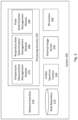
- FIG. 2 a block diagram schematically illustrating one example of a system for measuring temperature of subjects within a scene, in accordance with the presently disclosed subject matter.
- system 200 comprises a visible spectrum camera 240.
- Visible spectrum camera 240 is capable of acquiring images of scene 110.
- Visible spectrum camera 240 can be made of one or more sensors capable of acquiring images in at least the visible spectrum. The one or more sensors can be spatially distributed to acquire images of scene 110 from one or more locations and/or from one or more viewpoints.
- visible spectrum camera 240 is a high-definition camera, having a spatial resolution higher than 2mm/pixel in the relevant object plane.
- system 200 comprises a thermal image sensor 250.
- the thermal image sensor 250 is also capable of acquiring images of scene 110.
- the thermal image sensor 250 is an infrared (IR) image sensor capable of acquiring images of scene 110 in at least the IR spectrum.
- the thermal image sensor 250 is a near-infrared (NIR) image sensor capable of acquiring images of scene 110 in at least the NIR spectrum.
- Thermal image sensor 250 can be made of one or more sensors capable of acquiring images in at least the IR.
- the one or more thermal sensors can be spatially distributed to acquire thermal images of scene 110 from one or more locations and/or from one or more viewpoints.
- the thermal image sensor 250 is an uncooled thermal image sensor.
- System 200 can optionally comprise a three-dimensional (3D) camera 260.
- the 3D camera 260 is capable of acquiring 3D images of scene 110.
- 3D camera 260 creates digital 3D representations of the subjects (e.g. subject A 120-a, subject B 120-b, subject C 120-c) and/or the objects located within the scene 110.
- 3D camera 260 is a range camera capable of producing an image showing the distance to one or more points in scene 110 from a given location.
- 3D camera 260 produces a point cloud of scene 110.
- 3D camera 260 can be made of one or more sensors capable of acquiring images of scene 110.
- the one or more sensors can be spatially distributed to acquire images of scene 110 from one or more locations and/or from one or more viewpoints.
- the 3D camera's 260 sensors can be one or more of: a Light Imaging, Detection, and Ranging (LiDAR) sensor, a stereoscopic sensor, a Time of Flight (ToF) sensor, or any combinations thereof.
- LiDAR Light Imaging, Detection, and Ranging
- ToF Time of Flight
- System 200 can further comprise a network interface 220 enabling connecting the system 200 to a network and enabling it to send and receive data sent thereto through the network, including in some cases receiving information collected from one or more remote sensors, for example: receiving indication of the scene ambient temperature of scene 110 from a thermometer that is a location within scene 110.
- the network interface 220 can be connected to a Local Area Network (LAN), to a Wide Area Network (WAN), or to the Internet.
- the network interface 220 can connect to a wireless network.
- System 200 can further comprise or be otherwise associated with a data repository 210 (e.g. a database, a storage system, a memory including Read Only Memory - ROM, Random Access Memory - RAM, or any other type of memory, etc.) configured to store data, including, inter alia, information defining the spatial location of the RoIs (e.g. RoI A 130-a, RoI B 130-b, RoI C 130-c) within scene 110, point clouds of subjects (e.g. subject A 120-a, subject B 120-b, subject C 120-c) and/or objects located within scene 110, scene ambient temperature, threshold temperatures, etc.
- data repository 210 can be further configured to enable retrieval and/or update and/or deletion of the data stored thereon. It is to be noted that in some cases, data repository 210 can be distributed. It is to be noted that in some cases, data repository 210 can be stored in on cloud-based storage.
- System 200 further comprises processing circuitry 230.
- Processing circuitry 230 can be one or more processing circuitry units (e.g. central processing units), microprocessors, microcontrollers (e.g. microcontroller units (MCUs)) or any other computing devices or modules, including multiple and/or parallel and/or distributed processing circuitry units, which are adapted to independently or cooperatively process data for controlling relevant system 200 resources and for enabling operations related to system 200 resources.
- processing circuitry units e.g. central processing units
- microprocessors e.g. microcontroller units (MCUs)
- MCUs microcontroller units
- the processing circuitry 230 comprises one or more of the following modules: temperature measurement management module 270, respiratory rate determination management module 280, and pulse determination management module 290.
- Temperature measurement management module 270 can be configured to perform a temperature measurement process, as further detailed herein, inter alia with reference to Fig. 3 .
- Respiratory rate determination management module 280 can be configured to perform a respiratory rate determination process, as further detailed herein, inter alia with reference to Fig. 4 .
- Pulse determination management module 290 can be configured to perform a pulse determination process, as further detailed herein, inter alia with reference to Fig. 5 .
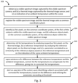
- FIG. 3 there is shown a flowchart illustrating one example of a sequence of operations carried out for temperature measurement, in accordance with the presently disclosed subject matter.
- system 200 can be configured to perform a temperature measurement process 300, e.g. utilizing the temperature measurement management module 270.
- system 200 is configured to obtain (a) a visible spectrum image captured by the visible spectrum camera 240, and (b) a thermal image captured by the thermal image sensor 250, and (c) an indication of a scene ambient temperature within the scene 110 (block 310).
- System 200 obtains a visible spectrum image of scene 110, which includes subjects (e.g. subject A 120-a, subject B 120-b, subject C 120-c), and a reference object 140 having an ambient temperature.
- the visible spectrum image comprises at least part of an RoI (e.g. RoI A 130-a, RoI B 130-b, RoI C 130-c) of at least one of the subjects (e.g. one of: subject A 120-a, subject B 120-b, subject C 120-c), and the reference object 140.
- the visible spectrum image is captured by the visible spectrum camera 240.
- the System 200 is configured to obtain a thermal image captured by the thermal image sensor 250.
- the thermal image comprises the at least RoI (e.g. RoI A 130-a, RoI B 130-b, RoI C 130-c) of each of the subjects (e.g. subject A 120-a, subject B 120-b, subject C 120-c) as comprised within the visible spectrum image.
- the thermal image also comprises the reference object 140.
- System 200 is configured to also obtain an indication of a scene ambient temperature within scene 110.
- the indication of the scene ambient temperature can be obtained from a thermometer measuring ambient temperature within scene 110.
- the thermometer can be external to system 200 or comprised as part of system 200.
- the indication of the scene ambient temperature can be received by system 200 from an external source, via a wired or wireless network by utilizing network interface 220.
- the indication of the scene ambient temperature can be determined by system 200 based on pre-defined properties of scene 110.
- system 200 obtains a visible spectrum image of scene 110 wherein RoI A 130-a of subject A 120-a and the reference object 140 are visible.
- System 200 also obtains a thermal image that comprises the thermal readings from RoI A 130-a and the thermal readings from reference object 140.
- System 200 also obtains an indication that the scene ambient temperature within scene 110 is 24 degrees Celsius.
- system 200 is further configured to register the visible spectrum image and the thermal image onto a common coordinate system (block 320).
- the registration of the visible spectrum image and the thermal image onto a common coordinate system enables system 200 to associate each pixel of the visible spectrum image to the corresponding pixel on the thermal image by utilizing the common coordinate system.
- the registration of the visible spectrum image and the thermal image onto a common coordinate system is required because of parallax effect between the thermal image sensor 250 and the visible spectrum camera 240.
- the registration sustains variation of distance between the sensors (e.g. visible spectrum camera 240 and thermal image sensor 250) and subjects (e.g. subject A 120-a, subject B 120-b, subject C 120-c and/or the reference object 140).
- system 200 includes a 3D camera 260 capable of acquiring depth images of the scene 110 comprising the at least RoI (e.g. RoI A 130-a, RoI B 130-b, RoI C 130-c) of each of the subjects (e.g. subject A 120-a, subject B 120-b, subject C 120-c) as comprised within the visible spectrum image.
- the registration of the visible spectrum image and the thermal image onto a common coordinate system can include also utilizing the depth images of the scene 110 for the registration.
- 3D camera 260 can obtain a depth image and system 200 can utilize the depth image for the registration of the visible spectrum image and the thermal image onto the common coordinate system in order to sustain variation of distance between the visible spectrum camera 240, the thermal image sensor 250, the 3D camera 260 and subjects (e.g. subject A 120-a, subject B 120-b, subject C 120-c) and/or the reference object 140 and/or the reference object 140.
- the distance dependent registration is required as different parts of scene 110 appear at different distance from visible spectrum camera 240, thermal image sensor 250 and from 3D camera 260.
- a registration of the visible spectrum image, the thermal image and the depth image is required.
- the registration can be a non-rigid registration.
- the registration utilizes the knowledge of the distance to each point in scene 110.
- usage of 3D camera 260 enables system 200 to create a point cloud, in which each point in scene 110 is associated with coordinates (e.g. X, Y, Z coordinates) with respect to the location of the 3D camera 260.
- the transformation of coordinates between different sensors e.g. visible spectrum camera 240, thermal image sensor 250 and 3D camera 260
- the preliminary calibration procedure can be realized by utilizing one or more known calibration methods.
- One non-limiting example is capturing of a given geometric pattern (e.g. a black and white checkboard pattern) observed by all sensors (e.g.
- visible spectrum camera 240, thermal image sensor 250 and 3D camera 260 during substitution of the given geometric pattern in a number of orientations and distances with respect to the sensors (e.g. visible spectrum camera 240, thermal image sensor 250 and 3D camera 260) which can be rigidly mounted .
- Another exemplary method of a preliminary calibration process of the sensors can be done by capturing an image of an object within scene 110 at one or more distances. This exemplary procedure allows an equivalence between the distance and the correct transformation of a point object from one of the sensor (e.g. one of: visible spectrum camera 240, thermal image sensor 250 and 3D camera 260) to another sensor (e.g.
- the preliminary calibration methods enable system 200 to apply a correction of image aberrations.
- the objects used for the preliminary calibration process are made from materials or are colored in a way that makes them observable by the sensors (e.g. visible spectrum camera 240, thermal image sensor 250 and 3D camera 260).
- system 200 registers the visible spectrum image and the thermal image onto a common coordination system.
- the registration allows a pixel-to-pixel correspondence between the pixels of the visible spectrum image and the pixels of the thermal image.
- system 200 utilizes a depth image of scene 110 for the registration and the depth data may be registered with the visible and the thermal images.
- system 200 is further configured to identify (a) RoI pixels, on the common coordinate system, of the RoIs (e.g. RoI A 130-a, RoI B 130-b, RoI C 130-c) of the subjects (e.g. subject A 120-a, subject B 120-b, subject C 120-c) within the visible spectrum image, and (b) reference object pixels, on the common coordinate system, of the reference object 140 within the visible spectrum image (block 330).
- RoI pixels on the common coordinate system, of the RoIs (e.g. RoI A 130-a, RoI B 130-b, RoI C 130-c) of the subjects (e.g. subject A 120-a, subject B 120-b, subject C 120-c) within the visible spectrum image
- reference object pixels on the common coordinate system, of the reference object 140 within the visible spectrum image
- System 200 can identify RoI pixels, on the common coordinate system, of the RoIs (e.g. RoI A 130-a, RoI B 130-b, RoI C 130-c) of the subjects (e.g. subject A 120-a, subject B 120-b, subject C 120-c) within the visible spectrum image.
- RoIs e.g. RoI A 130-a, RoI B 130-b, RoI C 130-c
- subjects e.g. subject A 120-a, subject B 120-b, subject C 120-c
- System 200 can be further configured to identify reference object pixels, on the common coordinate system, of the reference object 140 within the visible spectrum image.
- the identification of the RoI pixels can be realized by system 200 by performing an analysis of the visible spectrum image.
- the RoI pixels can be for example pixels of the subject's (e.g. subject A 120-a, subject B 120-b, subject C 120-c) head or of the area of the forehead or nostrils.
- the reference object pixels are the pixels of the visible spectrum image containing at least part of the reference object 140.
- the identification of the reference object pixels is based on a known shape of the reference object 140.
- the reference object 140 can have a specific rectangular shape and system 200 can analyze the visible spectrum image to identify the specific rectangular shape.
- the identification of the reference object pixels is based on a known location of the reference object 140 within scene 110.
- the reference object 140 can be locates in a lower right corner of scene 110 with respect to visible spectrum camera 240 and system 200 can analyze the visible spectrum image to identify the specific rectangular shape in that location.
- the reference object 140 includes one or more known symbols that are visible to the visible spectrum camera and/or to the thermal image sensor. In some cases, reference object 140, is not visible to the thermal image sensor. In these cases, the identification of the reference object pixels can be realized by system 200 analyzing the visible spectrum image to identify at least one of the known symbols.
- RoI A 130-a is the forehead of subject A 120-a.
- System 200 identifies the RoI pixels, which in our example are the pixels of RoI A 130-a by utilizing a head determination algorithm on the visible spectrum image.
- the reference object 140 in our non-limiting example is a cardboard with a known symbol printed thereon. The symbol is visible to visible spectrum camera 240.
- System 200 identifies the reference object pixels by analyzing the visible spectrum image to identify the known symbol.
- System 200 is further configured to determine RoI temperatures by analyzing respective RoIs pixels on the thermal image and a reference temperature by analyzing the reference object pixels on the thermal image (block 340).
- the RoI temperatures can be determined by system 200 by using the registration of both the visible spectrum image and the thermal image onto a common coordinate system to locate the RoIs pixels, which were identified by system 200 on the visible spectrum image, within the thermal image. These RoI pixels within the thermal image represent temperature of these RoIs (e.g. subject A 120-a, subject B 120-b, subject C 120-c) of the subjects (e.g. subject A 120-a, subject B 120-b, subject C 120-c) as measured by thermal image sensor 250.
- system 200 can analyze the RoI pixels associated with RoI A 130-a to determine the RoI temperature of the forehead of subject A 120-a is 36 degrees Celsius. Thus, subject's A 120-a temperature seems to be normal.
- the reference temperature can be determined by system 200 by using the registration of both the visible spectrum image and the thermal image onto a common coordinate system to locate the reference object pixels, identified on the visible spectrum image by system 200, within the thermal image. These reference object pixels within the thermal image represent the temperature of the reference object 140 as registered by thermal image sensor 250.
- system 200 can analyze the reference object pixels associated with the reference object 140 to determine the reference temperature to be 26 degrees Celsius.
- system 200 Upon existence of a difference between the reference temperature and the scene ambient temperature, system 200 is further configured to correct the RoI temperatures to compensate for the difference, giving rise to corrected RoI temperatures (block 350).
- Tobj_2 Tobj_1 + (T'obj_1 - T'obj_2) - ⁇ (Tref_1 - Tref_2) + f(Tamb_2)- f(Tamb_1)
- System 200 obtains an additional measurement at time t2, as follows:
- f(Tamb_1), f(Tamb_2) is a function for correction of the thermal image sensor 250 offset as a function of scene ambient temperature. This functionality may be embedded in the thermal imaging sensor 250 or may be supplied by its manufacturer. In case of f embedded in the reading of the thermal image sensor, the function f ⁇ 0.
- ⁇ is a calibration parameter describing the effect of the reference object's 140 temperature on the signal measured by the thermal image sensor 250.
- ⁇ depends on emissivity of the reference object's 140 material. However, in majority of practical cases the emissivity of the reference object 140 cannot be measured, for example: because physical access to the reference object 140 is limited.
- ⁇ can be calculated during an adaptive calibration procedure of system 200. In this procedure, the ambient temperature values and the reference object's 140 temperature as it is measured by the thermal image sensor 250 are measured at a plurality of point in time during a given time interval during which the ambient temperature may change.
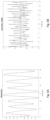
- Fig. 8A we show schematic records of a non-limiting example of reference object's 140 temperature values 800, measured by the thermal image sensor 250 at a plurality of point in time during the given time period, and in Fig.
- FIG. 8B we depict the ambient temperature measurements 900, measured during the same given time period.
- Figs. 8A and 8B demonstrate the variations of readings that result from the variation of the ambient temperature.
- Measurements 800 and 900 have areas with similar shapes (marked 850), having in some cases different scale, for the ambient temperature measurements 900 and for the reference temperature 800 as measured by the thermal image sensor 250.
- Measurements 800 and 900 have areas with differing shapes (marked 870). These readings result from changes of the thermal image sensor and are not correlated with the ambient temperature of scene 110. Analyzing the readings 800 and 900 from the ambient temperature of scene 110 and from reading from the thermal image sensor 250 of the same scene 110, enables evaluation of the parameter ⁇ .
- Example analysis methods include utilizing regression, least mean squares or by other numerical approaches on measurements 800 and 900.
- the detection of areas 850 and 870 can be performed, for example, by deep learning methods or by other analytical approaches.
- T'obj_k the y-axis value
- Tamb_k the argument values.
- Fig. 7A shows a non-limiting example of a simultaneous change in the temperature measuring by the thermal image sensor 250 on a human's forehead and on reference object 140.
- the results shown in Fig. 7B are the results of Fig. 7A , after subtraction of graph averages, thus allowing for better understanding of the correlation between the shift in the human's forehead temperature and the shift reference object 140 temperature.
- the offset shift in the reference temperature measuring can be used for the correction of the body temperature measuring.
- the correction expression can take into account effects of emissivity.
- the scene ambient temperature can be obtained by system 200 at any phase of process 300.
- Scene ambient temperature can be measured by a temperature sensor that is part of system 200 or by a sensor that is external to system 200.
- the temperature of reference object 140 is expected to be the scene ambient temperature or dependent on the scene ambient temperature on a known regularity.
- thermal image sensor 250 can be out of calibration, for example: thermal image sensor 250 was calibrated in one point in time but has gone out of calibration over time, there may be a difference between the reference temperature - being the temperature of reference object 140 as measured by thermal image sensor 250, and the actual temperature of reference object 140, being the scene ambient temperature obtained by system 200.
- System 200 can utilize the RoI temperatures to compensate for the difference, if any, and determine a corrected RoI temperature.
- System 200 can be configured to constantly calibrate thermal image sensor 250 utilizing reference object 140.
- the reference temperature knowledge also assists in reducing overall thermal sensor noise by utilizing noisy shift of the temperature measurement sensed by thermal image sensor 250.
- system 200 obtains an indication that the scene ambient temperature of scene 110 is 24 degrees Celsius. Therefore, there is a +2 degrees Celsius difference between the reference temperature and the scene ambient temperature. System 200 uses the difference to determine the corrected temperature of RoI A 130-a to be 38 degrees Celsius. Thus, subject's A 120-a temperature is actually indicative of a body temperature that exceed a threshold of temperture that are considered as healthy.
- the correction of the RoI temperatures can be also based on a distance of the respective subject (e.g. subject A 120-a, subject B 120-b, subject C 120-c) from the thermal image sensor 250.
- system 200 can use a moisture measuring device to obtain indication of the ambient moisture level and the effect of the moisture on the thermal radiation received by thermal image sensor 250 is associated with the distance of the subject (e.g. subject A 120-a, subject B 120-b, subject C 120-c) from the thermal image sensor 250.
- moisture within scene 110 can affect the absorption of the IR radiation and thereby cause a variation of the temperature measured by the thermal image sensor 250 as a function of distance between the thermal image sensor 250 and the subject (e.g.
- the correction of the RoI temperatures is dependent on the distance between the thermal image sensor 250 and the subject (e.g. subject A 120-a, subject B 120-b, subject C 120-c). This correction can provide high accuracy temperature measurements.
- system 200 can further configured to alert an operator of the system upon identifying subjects (e.g. subject A 120-a, subject B 120-b, subject C 120-c) associated with corrected RoI temperatures exceeding a threshold (block 360).
- subjects e.g. subject A 120-a, subject B 120-b, subject C 120-c
- an operator of system 200 can be looking on a screen of system 200 displaying the visible spectrum image and an indication that subject's A 120-a temperature exceeds 37.5 degrees Celsius.
- some of the blocks can be integrated into a consolidated block or can be broken down to a few blocks and/or other blocks may be added. Furthermore, in some cases, the blocks can be performed in a different order than described. It is to be further noted that some of the blocks are optional. It should be also noted that whilst the flow diagram is described also with reference to the system elements that realizes them, this is by no means binding, and the blocks can be performed by elements other than those described herein.
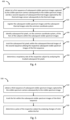
- Fig. 4 is a flowchart illustrating one example of a sequence of operations carried out for respiratory rate determination, in accordance with the presently disclosed subject matter.
- system 200 can be further configured to perform a respiratory rate determination process 400, e.g. utilizing the respiratory rate determination management module 280.
- system 200 can be configured to obtain a sequence of subsequent visible spectrum images captured by the visible spectrum camera 240 subsequently to the visible spectrum image and a sequence of subsequent thermal images captured by the thermal image sensor 250 subsequently to the thermal image (block 410).
- a non-limiting example can be a first sequence of visible spectrum images wherein RoI B 130-b is the area of the nostrils of subject B 120-b and is visible in the first sequence and a second sequence of thermal images wherein RoI B 130-b is visible.
- system 200 can be further configured to register the subsequent visible spectrum images and the subsequent thermal images onto the common coordinate system (block 420).
- the registration allows a pixel-to-pixel translation between the pixels of the first sequence of visible spectrum images and pixels of corresponding thermal images of the second sequence.
- system 200 can be further configured to identify subsequent RoI pixels, on the common coordinate system, of the RoIs (e.g. RoI A 130-a, RoI B 130-b, RoI C 130-c) of the subjects (e.g. subject A 120-a, subject B 120-b, subject C 120-c) within the subsequent visible spectrum images (block 430).
- the RoI pixels are the pixels of RoI B 130-b which are pixels in the area of the nostrils of subject B 120-b who is a human being.
- system 200 can be further configured to track the subsequent RoI pixels within the subsequent thermal images of the thermal images sequence.
- System 200 can track the subsequent RoI pixels within the subsequent thermal images of the thermal images sequence by utilizing the respective subsequent visible spectrum images of the visible spectrum images sequence (block 440).
- System 200 utilizes the subsequent visible spectrum images of the first sequence for the tracking by using known tracking algorithms. The tracking is done by determining the location of the pixels of the RoIs (e.g. RoI A 130-a, RoI B 130-b, RoI C 130-c) in the subsequent visible spectrum images of the visible spectrum images sequence. The system determines the location of the RoIs within each image of the pairs of images of this sequence and thus is able to track the RoI along the sequence of images. In some cases, system 200 tracks the subsequent RoI pixels within the subsequent thermal images of the second sequence without usage of the first sequence.
- System 200 can be further configured to determine a respiratory rate, which is the number of breaths a subject (e.g. one of: subject A 120-a, subject B 120-b, subject C 120-c) takes per minute, of the respective subject (e.g. one of: subject A 120-a, subject B 120-b, subject C 120-c) by analyzing the tracked subsequent RoI pixels for changes in temperature that occur as the respective subject (e.g. one of: subject A 120-a, subject B 120-b, subject C 120-c) exhales air (block 450).
- System 200 can also determine additional temporal information associated with the respiratory rate, such as: inhale time, exhale time, inhale to exhale time ration, etc.
- system 200 can determine the respiratory rate of subject B 120-b to be 15 breaths per minute, which is within the normal respiration rate range for an adult human being.
- Fig. 6A is a non-limiting example of a graph representing respiratory rate of a given subject (e.g. one of: subject A 120-a, subject B 120-b, subject C 120-c) as measured by system 200 over a given period of time.
- some of the blocks can be integrated into a consolidated block or can be broken down to a few blocks and/or other blocks may be added. Furthermore, in some cases, the blocks can be performed in a different order than described. It is to be further noted that some of the blocks are optional. It should be also noted that whilst the flow diagram is described also with reference to the system elements that realizes them, this is by no means binding, and the blocks can be performed by elements other than those described herein.
- FIG. 5 there is shown a flowchart illustrating one example of a sequence of operations carried out for pulse determination, in accordance with the presently disclosed subject matter.
- system 200 can be further configured to perform a pulse determination process 500, e.g. utilizing the pulse determination management module 290.
- system 200 can be configured to obtain a sequence of subsequent visible spectrum images captured by the visible spectrum camera subsequently to the visible spectrum image (block 510).
- a non-limiting example can be a sequence of visible spectrum images wherein RoI C 130-c is the area of the forehead of subject C 120-c who is an adult human being and is visible therein.
- system 200 can be further configured to track the RoI (e.g. RoI A 130-a, RoI B 130-b, RoI C 130-c) within the subsequent visible spectrum images of the sequence (block 520).
- System 200 utilizes the subsequent visible spectrum images of the third sequence for the tracking by using known tracking algorithms.
- system 200 can be further configured to determine a pulse of the respective subject (e.g. one of: subject A 120-a, subject B 120-b, subject C 120-c) by analyzing changes of color within the RoI (e.g. one of: RoI A 130-a, RoI B 130-b, RoI C 130-c).
- the changes of color are due to the blood flowing through the veins in accordance with the cardiac cycle of the respective subject (e.g. one of: subject A 120-a, subject B 120-b, subject C 120-c) (block 530).
- system 200 can determine the pulse rate of subject C 120-c to be 80 beats per minute, which is within the normal resting heart rate range for an adult human being, based on the changes of color of RoI C 130-c within the third sequence.
- Fig. 6B is a non-limiting example of a graph representing pulse rate of a subject (e.g. one of: subject A 120-a, subject B 120-b, subject C 120-c) as measured by the system 200 over a given period of time.
- some of the blocks can be integrated into a consolidated block or can be broken down to a few blocks and/or other blocks may be added. Furthermore, in some cases, the blocks can be performed in a different order than described. It is to be further noted that some of the blocks are optional. It should be also noted that whilst the flow diagram is described also with reference to the system elements that realizes them, this is by no means binding, and the blocks can be performed by elements other than those described herein.
- system can be implemented, at least partly, as a suitably programmed computer.
- the presently disclosed subject matter contemplates a computer program being readable by a computer for executing the disclosed method.
- the presently disclosed subject matter further contemplates a machine-readable memory tangibly embodying a program of instructions executable by the machine for executing the disclosed method.
Landscapes
- Health & Medical Sciences (AREA)
- Engineering & Computer Science (AREA)
- Life Sciences & Earth Sciences (AREA)
- Physics & Mathematics (AREA)
- General Health & Medical Sciences (AREA)
- General Physics & Mathematics (AREA)
- Medical Informatics (AREA)
- Theoretical Computer Science (AREA)
- Pathology (AREA)
- Biophysics (AREA)
- Biomedical Technology (AREA)
- Molecular Biology (AREA)
- Surgery (AREA)
- Animal Behavior & Ethology (AREA)
- Heart & Thoracic Surgery (AREA)
- Public Health (AREA)
- Veterinary Medicine (AREA)
- Multimedia (AREA)
- Physiology (AREA)
- Computer Vision & Pattern Recognition (AREA)
- Oral & Maxillofacial Surgery (AREA)
- Cardiology (AREA)
- Spectroscopy & Molecular Physics (AREA)
- Pulmonology (AREA)
- Nuclear Medicine, Radiotherapy & Molecular Imaging (AREA)
- Radiology & Medical Imaging (AREA)
- Quality & Reliability (AREA)
- Dentistry (AREA)
- Human Computer Interaction (AREA)
- Computer Networks & Wireless Communication (AREA)
- Artificial Intelligence (AREA)
- Computing Systems (AREA)
- Databases & Information Systems (AREA)
- Evolutionary Computation (AREA)
- Software Systems (AREA)
- Vascular Medicine (AREA)
- Radiation Pyrometers (AREA)
- Measuring And Recording Apparatus For Diagnosis (AREA)
- Image Processing (AREA)
Description
- The invention relates to a system and method for usage of high accuracy contactless temperature measurement for determination of physiological body parameters.
- Current contactless monitoring solutions utilize visual and thermal imagery for the measurement of body temperature and other medical indicators in order to help detect individuals that may be sick.
- These current contactless monitoring systems require highly accurate and expensive sensors or to compromise on worse performances using low cost sensors. Therefore, current low-cost systems are not easily adapted to operate in changing environmental conditions.
- There is thus a need in the art for a new body parameters measurement system and method.
- References considered to be relevant as background to the presently disclosed subject matter are listed below. Acknowledgement of the references herein is not to be inferred as meaning that these are in any way relevant to the patentability of the presently disclosed subject matter.
- WIPO International application No.
2019/162459 (MACNEISH et al.) published on August 29, 2019 , discloses a physiological monitoring apparatus (100) and methods are disclosed. A physiological monitor includes imaging sensors (120, 122, 124, 126), one of which is a time-of-flight imaging sensor (122). The physiological monitor (100) also includes a processing device (130) to receive data streams from the imaging sensors (120, 122, 124, 126). The processing device (130) may then extract time parameter data from the data streams, identify a physiological parameter from the extracted parameter data, and provide an indication of the physiological parameter. - MULTI-SPECTRAL FACIAL BIOMETRICS IN ACCESS CONTROL (Lai et al.) published on December, 2014, discloses how facial biometrics, acquired using multi-spectral sensors, such as RGB, depth, and infrared, assist the data accumulation in the process of authorizing users of automated and semi-automated access systems. This data serves the purposes of person authentication, as well as facial temperature estimation. We utilize depth data taken using an inexpensive RGB-D sensor to find the head pose of a subject. This allows the selection of video frames containing a frontal-view head pose for face recognition and face temperature reading. Usage of the frontal-view frames improves the efficiency of face recognition while the corresponding synchronized IR video frames allow for more efficient temperature estimation for facial regions of interest.
- WIPO International application No.
2015/086855 (BORNAND et al.) published on June 18, 2015 , discloses a tracking system comprising one or more cameras adapted to take images, one or more data processing units, said tracking system further comprising one or more output or display units, wherein said camera is adapted to observe a geographical area of interest, wherein said one or more data processing unit is configured to detect a moving entity in the area of interest, to identify a reference zone in at least some of said images, wherein said reference zone is on or associated with said moving entity, and to analyze the reference zone in order to determine at least one parameter associated with said moving entity. -
US Patent application No. 2019/0321719 (Gillian et al.) published on October 24, 2019 , discloses apparatuses and techniques for radar-enabled sensor fusion. In some aspects, a radar field is provided and reflection signals that correspond to a target in the radar field are received. The reflection signals are transformed to provide radar data, from which a radar feature indicating a physical characteristic of the target is extracted. Based on the radar features, a sensor is activated to provide supplemental sensor data associated with the physical characteristic. The radar feature is then augmented with the supplemental sensor data to enhance the radar feature, such as by increasing an accuracy or resolution of the radar feature. By so doing, performance of sensor-based applications, which rely on the enhanced radar features, can be improved. -
US Patent application No. 2018/0260680 (FINKELSTEIN et al.) published on September 13, 2018 , discloses intelligent assistant devices and methods for interacting with a user are disclosed. In some examples, a method for interacting with a user comprises predicting suggested action(s) for the user and displaying the action(s) via a display of the device. While the suggested action(s) are displayed, audio input comprising a command followed by a keyword is received from the user. The audio input is processed locally on the intelligent assistance device to (1) determine that the keyword follows the command and (2) recognize that the command applies to the suggested action(s). Based on determining that the keyword follows the command and recognizing that the command applies to the suggested action(s), a user selection of the suggested action(s) is established. Based on establishing the user selection, the one or more suggested actions are executed. -
US Patent application No. 2018/0143318 (Skowronek et al.) published on May 24, 2018 , discloses a passive-tracking system is described herein. The system can include a visible-light sensor, a sound transducer, a thermal sensor, a time-of-flight (ToF) sensor, and a processor. The processor can receive visible-light frames from the visible-light sensor, sound frames from the sound transducer, thermal frames from the thermal sensor, and modulated-light frames from the ToF sensor. The processor, based on data of the visible-light and temperature frames, can also determine that an object is a living being and can provide an X and Y position of the object. The processor, based on data of the sound and positioning frames, can determine a Z position of the object. The X, Y, and Z positions may combine to form a three-dimensional (3D) position of the object. The processor can also passively track the object over time by selectively updating the 3D position of the object. - Document
US 2019/080431 A1 discloses an imaging system including a 3D image capture device, which is configured to capture a depth image of an object, and a thermal image capture device, which is configured to capture a thermal image of the object. The imaging system also includes a processing system, which is coupled with the 3D image capture device and the thermal image capture device. The processing system is configured to process the depth image and the thermal image to produce a thermal-depth fusion image by aligning the thermal image with the depth image, and assigning a thermal value derived from the thermal image to a plurality of points of the depth image. - Document
KR 2017 0050936 A1 - Document
KR 101 729 327 B1 - Document
US 2007/153871 A1 discloses a system for fast noncontact screening for fever human subjects by means of a thermal imaging camera. The camera is combined with a target gate that incorporates the reference blackbody targets and position detectors to identify the temperature scale and size of a subject. - Document
US 2015/009335 A1 relates to a method for enabling improved calibration of captured infrared data values by an IR imaging system in a thermography arrangement dependent on an infrared (IR) image depicting an observed real world scene, said IR image being captured by a thermography arrangement comprising said IR imaging system, wherein infrared (IR) image is related to temperature dependent on IR calibration parameters, the method comprising: capturing an IR image depicting the observed real world scene using the IR imaging system, determining that a predefined feature is represented by IR pixels in the IR image and obtaining a second subset of said IR pixels representing said predefined feature; and calibrating said IR imaging system based on the captured infrared data values associated with said second subset of said IR pixels and a predetermined temperature value associated to said predefined feature. - Document
WO 2019/209887 A1 discloses systems and methods for mobile and augmented reality-based depth and thermal fusion scan imaging. - In accordance with a first aspect of the presently disclosed subject matter, there is provided a system for measuring temperature of at least two subjects within a scene including a reference object, the reference object having an unknown emissivity and an ambient temperature, wherein the ambient temperature of the reference object is the scene ambient temperature, the system comprising: a visible spectrum camera configured to acquire images of the scene comprising (a) at least a Region of Interest (RoI) of each of the subjects, and (b) the reference object; a thermal image sensor configured to acquire images of the scene comprising (a) at least the RoI of each of the subjects, and (b) the reference object; and a processing circuitry configured to: obtain (a) a visible spectrum image captured by the visible spectrum camera, and (b) a thermal image captured by the thermal image sensor, and (c) an indication of the scene ambient temperature within the scene; register the visible spectrum image and the thermal image onto a common coordinate system; identify (a) RoI pixels, on the common coordinate system, of the RoIs of the subjects within the visible spectrum image, and (b) reference object pixels, on the common coordinate system, of the reference object within the visible spectrum image; determine (a) RoI temperatures of the RoIs of the subjects by analyzing the identified RoI pixels on the thermal image, (b) a reference temperature by analyzing the reference object pixels on the thermal image, and (c) a parameter correlated to an emissivity of the reference object, based on the reference temperature and on the indication of the scene ambient temperature; and upon existence of a difference between the reference temperature and the indication of the scene ambient temperature, correct the RoI temperatures, based on the difference and utilizing the parameter, to compensate for the difference, giving rise to corrected RoI temperatures.
- In some cases, the determination of the parameter correlated to the emissivity of the reference object is performed by analyzing the reference temperature and the indication of the scene ambient temperature at a plurality of point in time during a given time period.
- In some cases, the system further comprising a three-dimensional (3D) camera capable of acquiring images of the scene comprising (a) at least a Region of Interest (RoI) of each of the subjects, and (b) the reference object, and wherein the processing circuitry is further configured to: obtain a depth image captured by the 3D camera; and utilize the depth image for the registration of the visible spectrum image and the thermal image onto the common coordinate system.
- In some cases, the correction of the RoI temperatures is also based on at least one of: (a) a distance of the respective subject from the thermal image sensor determined based on the analysis of the depth image, or (b) on ambient moisture level.
- In some cases, the indication of the ambient moisture level of is obtained from a moisture measuring device.
- In some cases, the indication of the scene ambient temperature is obtained from a thermometer measuring ambient temperature within the scene.
- In some cases, the thermal image sensor is uncooled.
- In some cases, the visible spectrum camera has a spatial resolution higher than 2mm/pixel.
- In some cases, the thermal spectrum camera has a spatial resolution higher than 2mm/pixel.
- In some cases, the subjects are living subjects.
- In some cases, the RoI is a body part of a body of the subject.
- In some cases, the subjects are animals and wherein the RoI is one or more of: a body part of a body of the respective animal subject, a face of the respective animal subject, a forehead of the respective animal subject, or a mouth of the respective animal subject.
- In some cases, the animals are human beings.
- In some cases, the subjects are plants and wherein the RoI is one or more of: a leaf of the respective plant subject, or a fruit of the respective plant subject.
- In some cases, the subjects are machines and wherein the RoI is an engine of the respective machine subject.
- In some cases, the reference object is diffusive and not specular.
- In some cases, the processing circuitry is further configured to alert an operator of the system upon identifying subjects associated with corrected RoI temperatures exceeding a threshold.
- In some cases, the reference object is made of material which temperature changes in a known manner according to changes to the scene ambient temperature.
- In some cases, the RoI is an area affected by breathing of the respective subject and wherein the processing circuitry is further configured to:obtain (a) a first sequence of subsequent visible spectrum images captured by the visible spectrum camera subsequently to the visible spectrum image, and (b) a second sequence of subsequent thermal images captured by the thermal image sensor subsequently to the thermal image; register the subsequent visible spectrum images and the subsequent thermal images onto the common coordinate system; identify subsequent RoI pixels, on the common coordinate system, of the RoIs of the subjects within the subsequent visible spectrum images; track the subsequent RoI pixels within the subsequent thermal images of the second sequence utilizing the respective subsequent visible spectrum images of the first sequence; and determine a respiratory rate of the respective subject by analyzing the tracked subsequent RoI pixels.
- In some cases, the RoI is a forehead of the respective subject and wherein the processing circuitry is further configured to: obtain a third sequence of subsequent visible spectrum images captured by the visible spectrum camera subsequently to the visible spectrum image; track the RoI within the subsequent visible spectrum images of the third sequence; and determine a pulse of the respective subject by analyzing changes of color within the RoI.
- In some cases, the reference object includes one or more symbols visible to the visible spectrum camera or to the thermal image sensor and wherein the reference object pixels are identified using at least one of the symbols.
- In accordance with a second aspect of the presently disclosed subject matter, there is provided a method for measuring temperature of at least two subjects within a scene including a reference object, the reference object having an unknown emissivity and an ambient temperature, wherein the ambient temperature of the reference object is the scene ambient temperature, the method comprising: obtaining, by a processing circuitry, (a) a visible spectrum image captured by a visible spectrum camera configured to acquire images of the scene comprising at least a Region of Interest (RoI) of each of the subjects, and the reference object, and (b) a thermal image captured by a thermal image sensor configured to acquire images of the scene comprising at least the RoI of each of the subjects, and the reference object, and (c) an indication of the scene ambient temperature within the scene; registering, by the processing circuitry, the visible spectrum image and the thermal image onto a common coordinate system; identifying, by the processing circuitry, (a) RoI pixels, on the common coordinate system, of the RoIs of the subjects within the visible spectrum image, and (b) reference object pixels, on the common coordinate system, of the reference object within the visible spectrum image; determining, by the processing circuitry, (a) RoI temperatures of the RoIs of the subjects, by analyzing the identified RoI pixels on the thermal image, (b) a reference temperature by analyzing the reference object pixels on the thermal image and (c) a parameter correlated to an emissivity of the reference object, based on the reference temperature and on the indication of the scene ambient temperature; and upon existence of a difference between the reference temperature and the indication of the scene ambient temperature, correcting, by the processing circuitry, the RoI temperatures, based on the difference and utilizing the parameter, to compensate for the difference, giving rise to corrected RoI temperatures.
- In some cases, the determination of the parameter correlated to the emissivity of the reference object is performed by analyzing the reference temperature and the indication of the scene ambient temperature at a plurality of point in time during a given time period.
- In some cases, the method further comprising: obtaining, by the processing circuitry, a depth image captured by a three-dimensional (3D) camera capable of acquiring images of the scene comprising (a) at least a Region of Interest (RoI) of each of the subjects, and (b) the reference object; and utilizing, by the processing circuitry, the depth image for the registration of the visible spectrum image and the thermal image onto the common coordinate system.
- In some cases, the correction of the RoI temperatures is also based on at least one of: (a) a distance of the respective subject from the thermal image sensor determined based on the analysis of the depth image, or (b) on ambient moisture level.
- In some cases, the indication of the ambient moisture level of is obtained from a moisture measuring device.
- In some cases, the indication of the scene ambient temperature is obtained from a thermometer measuring ambient temperature within the scene.
- In some cases, the thermal image sensor is uncooled.
- In some cases, the visible spectrum camera has a spatial resolution higher than 2mm/pixel.
- In some cases, the thermal spectrum camera has a spatial resolution higher than 2mm/pixel.
- In some cases, the subjects are living subjects.
- In some cases, the RoI is a body part of a body of the subject.
- In some cases, the subjects are animals and wherein the RoI is one or more of: a body part of a body of the respective animal subject, a face of the respective animal subject, a forehead of the respective animal subject, or a mouth of the respective animal subject.
- In some cases, the animals are human beings.
- In some cases, the subjects are plants and wherein the RoI is one or more of: a leaf of the respective plant subject, or a fruit of the respective plant subject.
- In some cases, the subjects are machines and wherein the RoI is an engine of the respective machine subject.
- In some cases, the reference object is diffusive and not specular.
- In some cases, the method further comprising alerting, by the processing circuitry, an operator of the system upon identifying subjects associated with corrected RoI temperatures exceeding a threshold.
- In some cases, the reference object is made of material which temperature changes in a known manner according to changes to the scene ambient temperature.
- In some cases, the RoI is an area affected by breathing of the respective subject and wherein method further comprising: obtaining, by the processing circuitry, (a) a first sequence of subsequent visible spectrum images captured by the visible spectrum camera subsequently to the visible spectrum image, and (b) a second sequence of subsequent thermal images captured by the thermal image sensor subsequently to the thermal image; registering, by the processing circuitry, the subsequent visible spectrum images and the subsequent thermal images onto the common coordinate system; identifying, by the processing circuitry, subsequent RoI pixels, on the common coordinate system, of the RoIs of the subjects within the subsequent visible spectrum images; tracking, by the processing circuitry, the subsequent RoI pixels within the subsequent thermal images of the second sequence utilizing the respective subsequent visible spectrum images of the first sequence; and determining, by the processing circuitry, a respiratory rate of the respective subject by analyzing the tracked subsequent RoI pixels.
- In some cases, the RoI is a forehead of the respective subject and wherein the method further comprising: obtaining, by the processing circuitry, a third sequence of subsequent visible spectrum images captured by the visible spectrum camera subsequently to the visible spectrum image; tracking, by the processing circuitry, the RoI within the subsequent visible spectrum images of the third sequence; and determining, by the processing circuitry, a pulse of the respective subject by analyzing changes of color within the RoI.
- In some cases, the reference object includes one or more symbols visible to the visible spectrum camera or to the thermal image sensor and wherein the reference object pixels are identified using at least one of the symbols.
- In accordance with a third aspect of the presently disclosed subject matter, there is provided a non-transitory computer readable storage medium having computer readable program code embodied therewith, the computer readable program code, executable by at least one processing circuitry of a computer to perform a method for measuring temperature of at least two subjects within a scene including a reference object, the reference object having an unknown emissivity and an ambient temperature, wherein the ambient temperature of the reference object is the scene ambient temperature, the method comprising: obtaining, by a processing circuitry, (a) a visible spectrum image captured by a visible spectrum camera configured to acquire images of the scene comprising at least a Region of Interest (RoI) of each of the subjects, and the reference object, and (b) a thermal image captured by a thermal image sensor configured to acquire images of the scene comprising at least the RoI of each of the subjects, and the reference object, and (c) an indication of the scene ambient temperature within the scene; registering, by the processing circuitry, the visible spectrum image and the thermal image onto a common coordinate system; identifying, by the processing circuitry, (a) RoI pixels, on the common coordinate system, of the RoIs of the subjects within the visible spectrum image, and (b) reference object pixels, on the common coordinate system, of the reference object within the visible spectrum image; determining, by the processing circuitry, (a) RoI temperatures of the RoIs of the subjects, by analyzing the identified RoI pixels on the thermal image, (b) a reference temperature by analyzing the reference object pixels on the thermal image and (c) a parameter correlated to an emissivity of the reference object, based on the reference temperature and on the indication of the scene ambient temperature; and upon existence of a difference between the reference temperature and the indication of the scene ambient temperature, correcting, by the processing circuitry, the RoI temperatures, based on the difference and utilizing the parameter, to compensate for the difference, giving rise to corrected RoI temperatures.
- In order to understand the presently disclosed subject matter and to see how it may be carried out in practice, the subject matter will now be described, by way of non-limiting examples only, with reference to the accompanying drawings, in which:
-
Fig. 1 is a schematic illustration of an example scene with subjects and a reference object, in accordance with the presently disclosed subject matter; -
Fig. 2 is a block diagram schematically illustrating one example of a system for measuring temperature of subjects within a scene, in accordance with the presently disclosed subject matter; -
Fig. 3 is a flowchart illustrating one example of a sequence of operations carried out for temperature measurement, in accordance with the presently disclosed subject matter; -
Fig. 4 is a flowchart illustrating one example of a sequence of operations carried out for respiratory rate determination, in accordance with the presently disclosed subject matter; -
Fig. 5 is a flowchart illustrating one example of a sequence of operations carried out for pulse determination, in accordance with the presently disclosed subject matter; -
Fig. 6A is a non-limiting example of a graph representing respiratory rate as measured by the system; -
Fig. 6B is a non-limiting example of a graph representing pulse as measured by the system; -
Fig. 7A is a non-limiting example of a graph representing temperature measurements as measured by the system; -
Fig. 7B is a non-limiting example of the graph ofFig. 7A after subtraction of graph averages; -
Fig. 8A depicts schematic records of a non-limiting example of reference object's temperature values; and -
Fig. 8B depict a non-limiting example of ambient temperature measurements, measured during a given time period. - In the following detailed description, numerous specific details are set forth in order to provide a thorough understanding of the presently disclosed subject matter. However, it will be understood by those skilled in the art that the presently disclosed subject matter may be practiced without these specific details. In other instances, well-known methods, procedures, and components have not been described in detail so as not to obscure the presently disclosed subject matter.
- In the drawings and descriptions set forth, identical reference numerals indicate those components that are common to different embodiments or configurations.
- Unless specifically stated otherwise, as apparent from the following discussions, it is appreciated that throughout the specification discussions utilizing terms such as "obtaining", "registering", "identifying", "determining", "correcting", "tracking" or the like, include action and/or processes of a computer that manipulate and/or transform data into other data, said data represented as physical quantities, e.g. such as electronic quantities, and/or said data representing the physical objects. The terms "computer", "processor", "processing resource" and "controller" should be expansively construed to cover any kind of electronic device with data processing capabilities, including, by way of non-limiting example, a personal desktop/laptop computer, a server, a computing system, a communication device, a smartphone, a tablet computer, a smart television, a processor (e.g. digital signal processor (DSP), a microcontroller, a field programmable gate array (FPGA), an application specific integrated circuit (ASIC), etc.), a group of multiple physical machines sharing performance of various tasks, virtual servers co-residing on a single physical machine, any other electronic computing device, and/or any combination thereof.
- The operations in accordance with the teachings herein may be performed by a computer specially constructed for the desired purposes or by a general-purpose computer specially configured for the desired purpose by a computer program stored in a non-transitory computer readable storage medium. The term "non-transitory" is used herein to exclude transitory, propagating signals, but to otherwise include any volatile or non-volatile computer memory technology suitable to the application.
- As used herein, the phrase "for example," "such as", "for instance" and variants thereof describe non-limiting embodiments of the presently disclosed subject matter. Reference in the specification to "one case", "some cases", "other cases" or variants thereof means that a particular feature, structure or characteristic described in connection with the embodiment(s) is included in at least one embodiment of the presently disclosed subject matter. Thus, the appearance of the phrase "one case", "some cases", "other cases" or variants thereof does not necessarily refer to the same embodiment(s).
- It is appreciated that, unless specifically stated otherwise, certain features of the presently disclosed subject matter, which are, for clarity, described in the context of separate embodiments, may also be provided in combination in a single embodiment. Conversely, various features of the presently disclosed subject matter, which are, for brevity, described in the context of a single embodiment, may also be provided separately or in any suitable sub-combination.
- In embodiments of the presently disclosed subject matter, fewer, more and/or different stages than those shown in
Figs. 3-5 may be executed. In embodiments of the presently disclosed subject matter one or more stages illustrated inFigs. 3-5 may be executed in a different order and/or one or more groups of stages may be executed simultaneously.Figs. 1-2 illustrate a general schematic of the system architecture in accordance with an embodiment of the presently disclosed subject matter. Each module inFigs. 1-2 can be made up of any combination of software, hardware and/or firmware that performs the functions as defined and explained herein. The modules inFigs. 1-2 may be centralized in one location or dispersed over more than one location. In other embodiments of the presently disclosed subject matter, the system may comprise fewer, more, and/or different modules than those shown inFigs. 1-2 . - Any reference in the specification to a method should be applied mutatis mutandis to a system capable of executing the method and should be applied mutatis mutandis to a non-transitory computer readable medium that stores instructions that once executed by a computer result in the execution of the method.
- Any reference in the specification to a system should be applied mutatis mutandis to a method that may be executed by the system and should be applied mutatis mutandis to a non-transitory computer readable medium that stores instructions that may be executed by the system.
- Any reference in the specification to a non-transitory computer readable medium should be applied mutatis mutandis to a system capable of executing the instructions stored in the non-transitory computer readable medium and should be applied mutatis mutandis to method that may be executed by a computer that reads the instructions stored in the non-transitory computer readable medium.
- Bearing this in mind, attention is drawn to
Fig. 1 , a schematic illustration of an example scene with subjects and a reference object, in accordance with the presently disclosed subject matter. -
Scene 110 includes subjects (e.g. subject A 120-a, subject B 120-b, subject C 120-c). The subjects can be human beings, animals, plants, machines or any other heat emitting objects.Scene 110 is viewable by one or more sensors. The sensors can take at least one image ofscene 110 which includes at least part of the subjects and at least part of a reference objects 140. In some cases, at least parts of the subjects are Regions of Interest (RoIs) (e.g. RoI A 130-a, RoI B 130-b, RoI C 130-c). The RoIs can include a face of a respective subject, a forehead of the respective subject, a mouth of the respective subject or any other body part of the respective subject. A non-limiting example can be that subject A 120-a is a human being and RoI A 130-a includes at least an area of subject's A 120-a forehead. -
Scene 110 can additionally include one or more reference objects 140.Reference object 140 can be made of material whose temperature changes in a known manner according to changes to the scene ambient temperature withinscene 110. According to the claimed invention, the temperature of thereference object 140 is the scene ambient temperature. In some cases, thereference object 140 is at least part of a cardboard. - In some cases, the
reference object 140 is diffusive and not specular, thus does not have mirror-like properties of wave reflection. It is to be noted thatreference object 140 is not a black body. - In some cases, the
reference object 140 includes one or more known symbols that are visible to a visible spectrum camera or to a thermal image sensor or to both the visible spectrum camera and the thermal image sensor, in some cases the known symbols are visible to the visible spectrum camera and not to the thermal image sensor, as further detailed herein, inter alia with reference toFig. 3 . -
Scene 110 can be indoors, for example: a reception area of a medical practitioner, where patients await reception by the medical practitioner. In some cases,scene 110 is outdoors, for example:scene 110 can be part of a park where people and animals are roaming around. In some cases,scene 110 is a large space including a large number of subjects, for example: part of a busy airport or train station. - It is to be noted that the subjects within
scene 110 can be stationary and/or moving withinscene 110. - Having briefly described a scene with subjects and a reference object, attention is drawn to
Fig. 2 , a block diagram schematically illustrating one example of a system for measuring temperature of subjects within a scene, in accordance with the presently disclosed subject matter. - According to certain examples of the presently disclosed subject matter,
system 200 comprises avisible spectrum camera 240.Visible spectrum camera 240 is capable of acquiring images ofscene 110.Visible spectrum camera 240 can be made of one or more sensors capable of acquiring images in at least the visible spectrum. The one or more sensors can be spatially distributed to acquire images ofscene 110 from one or more locations and/or from one or more viewpoints. In some cases,visible spectrum camera 240 is a high-definition camera, having a spatial resolution higher than 2mm/pixel in the relevant object plane. - In addition,
system 200 comprises athermal image sensor 250. Thethermal image sensor 250 is also capable of acquiring images ofscene 110. In some cases, thethermal image sensor 250 is an infrared (IR) image sensor capable of acquiring images ofscene 110 in at least the IR spectrum. In some cases, thethermal image sensor 250 is a near-infrared (NIR) image sensor capable of acquiring images ofscene 110 in at least the NIR spectrum.Thermal image sensor 250 can be made of one or more sensors capable of acquiring images in at least the IR. The one or more thermal sensors can be spatially distributed to acquire thermal images ofscene 110 from one or more locations and/or from one or more viewpoints. In some cases, thethermal image sensor 250 is an uncooled thermal image sensor. -
System 200 can optionally comprise a three-dimensional (3D)camera 260. The3D camera 260 is capable of acquiring 3D images ofscene 110. In some cases,3D camera 260 creates digital 3D representations of the subjects (e.g. subject A 120-a, subject B 120-b, subject C 120-c) and/or the objects located within thescene 110. In some cases,3D camera 260 is a range camera capable of producing an image showing the distance to one or more points inscene 110 from a given location. In some cases,3D camera 260 produces a point cloud ofscene 110.3D camera 260 can be made of one or more sensors capable of acquiring images ofscene 110. The one or more sensors can be spatially distributed to acquire images ofscene 110 from one or more locations and/or from one or more viewpoints. The 3D camera's 260 sensors can be one or more of: a Light Imaging, Detection, and Ranging (LiDAR) sensor, a stereoscopic sensor, a Time of Flight (ToF) sensor, or any combinations thereof. -
System 200 can further comprise anetwork interface 220 enabling connecting thesystem 200 to a network and enabling it to send and receive data sent thereto through the network, including in some cases receiving information collected from one or more remote sensors, for example: receiving indication of the scene ambient temperature ofscene 110 from a thermometer that is a location withinscene 110. In some cases, thenetwork interface 220 can be connected to a Local Area Network (LAN), to a Wide Area Network (WAN), or to the Internet. In some cases, thenetwork interface 220 can connect to a wireless network. -
System 200 can further comprise or be otherwise associated with a data repository 210 (e.g. a database, a storage system, a memory including Read Only Memory - ROM, Random Access Memory - RAM, or any other type of memory, etc.) configured to store data, including, inter alia, information defining the spatial location of the RoIs (e.g. RoI A 130-a, RoI B 130-b, RoI C 130-c) withinscene 110, point clouds of subjects (e.g. subject A 120-a, subject B 120-b, subject C 120-c) and/or objects located withinscene 110, scene ambient temperature, threshold temperatures, etc. In some cases,data repository 210 can be further configured to enable retrieval and/or update and/or deletion of the data stored thereon. It is to be noted that in some cases,data repository 210 can be distributed. It is to be noted that in some cases,data repository 210 can be stored in on cloud-based storage. -
System 200 further comprisesprocessing circuitry 230.Processing circuitry 230 can be one or more processing circuitry units (e.g. central processing units), microprocessors, microcontrollers (e.g. microcontroller units (MCUs)) or any other computing devices or modules, including multiple and/or parallel and/or distributed processing circuitry units, which are adapted to independently or cooperatively process data for controllingrelevant system 200 resources and for enabling operations related tosystem 200 resources. - The
processing circuitry 230 comprises one or more of the following modules: temperaturemeasurement management module 270, respiratory ratedetermination management module 280, and pulsedetermination management module 290. - Temperature
measurement management module 270 can be configured to perform a temperature measurement process, as further detailed herein, inter alia with reference toFig. 3 . - Respiratory rate
determination management module 280 can be configured to perform a respiratory rate determination process, as further detailed herein, inter alia with reference toFig. 4 . - Pulse
determination management module 290 can be configured to perform a pulse determination process, as further detailed herein, inter alia with reference toFig. 5 . - Turning to
Fig. 3 , there is shown a flowchart illustrating one example of a sequence of operations carried out for temperature measurement, in accordance with the presently disclosed subject matter. - According to certain examples of the presently disclosed subject matter,
system 200 can be configured to perform atemperature measurement process 300, e.g. utilizing the temperaturemeasurement management module 270. - For this purpose,
system 200 is configured to obtain (a) a visible spectrum image captured by thevisible spectrum camera 240, and (b) a thermal image captured by thethermal image sensor 250, and (c) an indication of a scene ambient temperature within the scene 110 (block 310). -
System 200 obtains a visible spectrum image ofscene 110, which includes subjects (e.g. subject A 120-a, subject B 120-b, subject C 120-c), and areference object 140 having an ambient temperature. The visible spectrum image comprises at least part of an RoI (e.g. RoI A 130-a, RoI B 130-b, RoI C 130-c) of at least one of the subjects (e.g. one of: subject A 120-a, subject B 120-b, subject C 120-c), and thereference object 140. The visible spectrum image is captured by thevisible spectrum camera 240. -
System 200 is configured to obtain a thermal image captured by thethermal image sensor 250. The thermal image comprises the at least RoI (e.g. RoI A 130-a, RoI B 130-b, RoI C 130-c) of each of the subjects (e.g. subject A 120-a, subject B 120-b, subject C 120-c) as comprised within the visible spectrum image. The thermal image also comprises thereference object 140. -
System 200 is configured to also obtain an indication of a scene ambient temperature withinscene 110. In some cases, the indication of the scene ambient temperature can be obtained from a thermometer measuring ambient temperature withinscene 110. The thermometer can be external tosystem 200 or comprised as part ofsystem 200. In some cases, the indication of the scene ambient temperature can be received bysystem 200 from an external source, via a wired or wireless network by utilizingnetwork interface 220. In some case, the indication of the scene ambient temperature can be determined bysystem 200 based on pre-defined properties ofscene 110. - In a non-limiting example,
system 200 obtains a visible spectrum image ofscene 110 wherein RoI A 130-a of subject A 120-a and thereference object 140 are visible.System 200 also obtains a thermal image that comprises the thermal readings from RoI A 130-a and the thermal readings fromreference object 140.System 200 also obtains an indication that the scene ambient temperature withinscene 110 is 24 degrees Celsius. - After obtaining the visible spectrum image, the thermal image,
system 200 is further configured to register the visible spectrum image and the thermal image onto a common coordinate system (block 320). The registration of the visible spectrum image and the thermal image onto a common coordinate system enablessystem 200 to associate each pixel of the visible spectrum image to the corresponding pixel on the thermal image by utilizing the common coordinate system. In some cases, the registration of the visible spectrum image and the thermal image onto a common coordinate system is required because of parallax effect between thethermal image sensor 250 and thevisible spectrum camera 240. The registration sustains variation of distance between the sensors (e.g.visible spectrum camera 240 and thermal image sensor 250) and subjects (e.g. subject A 120-a, subject B 120-b, subject C 120-c and/or the reference object 140). - In some cases,
system 200 includes a3D camera 260 capable of acquiring depth images of thescene 110 comprising the at least RoI (e.g. RoI A 130-a, RoI B 130-b, RoI C 130-c) of each of the subjects (e.g. subject A 120-a, subject B 120-b, subject C 120-c) as comprised within the visible spectrum image. The registration of the visible spectrum image and the thermal image onto a common coordinate system can include also utilizing the depth images of thescene 110 for the registration. In these cases,3D camera 260 can obtain a depth image andsystem 200 can utilize the depth image for the registration of the visible spectrum image and the thermal image onto the common coordinate system in order to sustain variation of distance between thevisible spectrum camera 240, thethermal image sensor 250, the3D camera 260 and subjects (e.g. subject A 120-a, subject B 120-b, subject C 120-c) and/or thereference object 140 and/or thereference object 140. The distance dependent registration is required as different parts ofscene 110 appear at different distance fromvisible spectrum camera 240,thermal image sensor 250 and from3D camera 260. In some cases, a registration of the visible spectrum image, the thermal image and the depth image is required. In some cases, the registration can be a non-rigid registration. The registration utilizes the knowledge of the distance to each point inscene 110. In some cases, usage of3D camera 260 enablessystem 200 to create a point cloud, in which each point inscene 110 is associated with coordinates (e.g. X, Y, Z coordinates) with respect to the location of the3D camera 260. in some cases, the transformation of coordinates between different sensors (e.g.visible spectrum camera 240,thermal image sensor visible spectrum camera 240,thermal image sensor visible spectrum camera 240,thermal image sensor visible spectrum camera 240,thermal image sensor scene 110 at one or more distances. This exemplary procedure allows an equivalence between the distance and the correct transformation of a point object from one of the sensor (e.g. one of:visible spectrum camera 240,thermal image sensor visible spectrum camera 240,thermal image sensor system 200 to apply a correction of image aberrations. In some cases, the objects used for the preliminary calibration process are made from materials or are colored in a way that makes them observable by the sensors (e.g.visible spectrum camera 240,thermal image sensor - Continuing the above non-limiting example,
system 200 registers the visible spectrum image and the thermal image onto a common coordination system. The registration allows a pixel-to-pixel correspondence between the pixels of the visible spectrum image and the pixels of the thermal image. In some cases,system 200 utilizes a depth image ofscene 110 for the registration and the depth data may be registered with the visible and the thermal images. - After registering the visible spectrum image and the thermal image onto a common coordinate system,
system 200 is further configured to identify (a) RoI pixels, on the common coordinate system, of the RoIs (e.g. RoI A 130-a, RoI B 130-b, RoI C 130-c) of the subjects (e.g. subject A 120-a, subject B 120-b, subject C 120-c) within the visible spectrum image, and (b) reference object pixels, on the common coordinate system, of thereference object 140 within the visible spectrum image (block 330). -
System 200 can identify RoI pixels, on the common coordinate system, of the RoIs (e.g. RoI A 130-a, RoI B 130-b, RoI C 130-c) of the subjects (e.g. subject A 120-a, subject B 120-b, subject C 120-c) within the visible spectrum image. -
System 200 can be further configured to identify reference object pixels, on the common coordinate system, of thereference object 140 within the visible spectrum image. - The identification of the RoI pixels can be realized by
system 200 by performing an analysis of the visible spectrum image. The RoI pixels can be for example pixels of the subject's (e.g. subject A 120-a, subject B 120-b, subject C 120-c) head or of the area of the forehead or nostrils. The reference object pixels are the pixels of the visible spectrum image containing at least part of thereference object 140. - In some cases, the identification of the reference object pixels is based on a known shape of the
reference object 140. For example, thereference object 140 can have a specific rectangular shape andsystem 200 can analyze the visible spectrum image to identify the specific rectangular shape. - In some cases, the identification of the reference object pixels is based on a known location of the
reference object 140 withinscene 110. For example, thereference object 140 can be locates in a lower right corner ofscene 110 with respect tovisible spectrum camera 240 andsystem 200 can analyze the visible spectrum image to identify the specific rectangular shape in that location. - In some cases, the
reference object 140 includes one or more known symbols that are visible to the visible spectrum camera and/or to the thermal image sensor. In some cases,reference object 140, is not visible to the thermal image sensor. In these cases, the identification of the reference object pixels can be realized bysystem 200 analyzing the visible spectrum image to identify at least one of the known symbols. - Continuing the above non-limiting example, RoI A 130-a is the forehead of subject A 120-a.
System 200 identifies the RoI pixels, which in our example are the pixels of RoI A 130-a by utilizing a head determination algorithm on the visible spectrum image. Thereference object 140 in our non-limiting example is a cardboard with a known symbol printed thereon. The symbol is visible tovisible spectrum camera 240.System 200 identifies the reference object pixels by analyzing the visible spectrum image to identify the known symbol. -
System 200 is further configured to determine RoI temperatures by analyzing respective RoIs pixels on the thermal image and a reference temperature by analyzing the reference object pixels on the thermal image (block 340). - The RoI temperatures can be determined by
system 200 by using the registration of both the visible spectrum image and the thermal image onto a common coordinate system to locate the RoIs pixels, which were identified bysystem 200 on the visible spectrum image, within the thermal image. These RoI pixels within the thermal image represent temperature of these RoIs (e.g. subject A 120-a, subject B 120-b, subject C 120-c) of the subjects (e.g. subject A 120-a, subject B 120-b, subject C 120-c) as measured bythermal image sensor 250. - Continuing the non-limiting example from above,
system 200 can analyze the RoI pixels associated with RoI A 130-a to determine the RoI temperature of the forehead of subject A 120-a is 36 degrees Celsius. Thus, subject's A 120-a temperature seems to be normal. - Similarly, the reference temperature can be determined by
system 200 by using the registration of both the visible spectrum image and the thermal image onto a common coordinate system to locate the reference object pixels, identified on the visible spectrum image bysystem 200, within the thermal image. These reference object pixels within the thermal image represent the temperature of thereference object 140 as registered bythermal image sensor 250. - Continuing the non-limiting example from above,
system 200 can analyze the reference object pixels associated with thereference object 140 to determine the reference temperature to be 26 degrees Celsius. - Upon existence of a difference between the reference temperature and the scene ambient temperature,
system 200 is further configured to correct the RoI temperatures to compensate for the difference, giving rise to corrected RoI temperatures (block 350). - An exemplary mathematical expression of the correction used to correct the RoI temperatures to compensate for the difference can be the following expression:
Tobj_2 = Tobj_1 + (T'obj_1 - T'obj_2) - α· (Tref_1 - Tref_2) + f(Tamb_2)- f(Tamb_1) - Where the exemplary mathematical expression is formed by supposing that one of the measurements was taken at time t1 such that the following values are obtained by system 200:
- Tobj_1 - the real temperature of an object (the object can be for example one of: subject A 120-a, subject B 120-b, subject C 120-c) that can be measured by a golden standard equipment;
- T'obj_1 - the object temperature as it is measured by the
thermal image sensor 250 in the pre-defined RoI; - Tamb_1 - the scene ambient temperature; and
- Tref_1 - the temperature of the
reference object 140 that is the same as the scene ambient temperature at the measurement moment t1. -
System 200 obtains an additional measurement at time t2, as follows: - T'obj_2 - object temperature as it is measured by the
thermal image sensor 250 in the pre-defined RoI; - Tamb_2 - scene ambient temperature at the time t2; and
- Tref_2 - temperature of the
reference object 140 that is the same as the scene's ambient temperature at the measurement moment t2. - f(Tamb_1), f(Tamb_2) is a function for correction of the
thermal image sensor 250 offset as a function of scene ambient temperature. This functionality may be embedded in thethermal imaging sensor 250 or may be supplied by its manufacturer. In case of f embedded in the reading of the thermal image sensor, the function f≡0. - α is a calibration parameter describing the effect of the reference object's 140 temperature on the signal measured by the
thermal image sensor 250. - The temperature at both moments t1 and t2 are at steady states.
- Practically, α depends on emissivity of the reference object's 140 material. However, in majority of practical cases the emissivity of the
reference object 140 cannot be measured, for example: because physical access to thereference object 140 is limited. In some embodiments α can be calculated during an adaptive calibration procedure ofsystem 200. In this procedure, the ambient temperature values and the reference object's 140 temperature as it is measured by thethermal image sensor 250 are measured at a plurality of point in time during a given time interval during which the ambient temperature may change. InFig. 8A we show schematic records of a non-limiting example of reference object's 140temperature values 800, measured by thethermal image sensor 250 at a plurality of point in time during the given time period, and inFig. 8B we depict theambient temperature measurements 900, measured during the same given time period.Figs. 8A and 8B demonstrate the variations of readings that result from the variation of the ambient temperature.Measurements ambient temperature measurements 900 and for thereference temperature 800 as measured by thethermal image sensor 250.Measurements scene 110. Analyzing thereadings scene 110 and from reading from thethermal image sensor 250 of thesame scene 110, enables evaluation of the parameter α. Example analysis methods include utilizing regression, least mean squares or by other numerical approaches onmeasurements areas - As a non-limiting example, we present here a way for calculation of the parameter α:
In this evaluation we suppose that the studied object is thereference object 140 itself and its temperature is the ambient temperature is expressed by the following equations:

thermal image sensor 250 reading. These data sets can be used to calculate the parameter α. For example, it can be done as a calculation of a slope of regression in a function where the T'obj_k represents the y-axis value and Tamb_k represents the argument values. In case that f(Tamb_k) is embedded in the reading of thethermal image sensor 250, the function f(Tamb_k)≡0. - The above exemplary mathematical expression can provide a correction of the offset shift in the
thermal image sensor 250.Fig. 7A shows a non-limiting example of a simultaneous change in the temperature measuring by thethermal image sensor 250 on a human's forehead and onreference object 140. The results shown inFig. 7B are the results ofFig. 7A , after subtraction of graph averages, thus allowing for better
understanding of the correlation between the shift in the human's forehead temperature and theshift reference object 140 temperature. The offset shift in the reference temperature measuring can be used for the correction of the body temperature measuring. In some cases, the correction expression can take into account effects of emissivity. - The scene ambient temperature can be obtained by
system 200 at any phase ofprocess 300. Scene ambient temperature can be measured by a temperature sensor that is part ofsystem 200 or by a sensor that is external tosystem 200. - As explained above, the temperature of
reference object 140 is expected to be the scene ambient temperature or dependent on the scene ambient temperature on a known regularity. Asthermal image sensor 250 can be out of calibration, for example:thermal image sensor 250 was calibrated in one point in time but has gone out of calibration over time, there may be a difference between the reference temperature - being the temperature ofreference object 140 as measured bythermal image sensor 250, and the actual temperature ofreference object 140, being the scene ambient temperature obtained bysystem 200.System 200 can utilize the RoI temperatures to compensate for the difference, if any, and determine a corrected RoI temperature.System 200 can be configured to constantly calibratethermal image sensor 250 utilizingreference object 140. The reference temperature knowledge also assists in reducing overall thermal sensor noise by utilizing noisy shift of the temperature measurement sensed bythermal image sensor 250. - Continuing the non-limiting example from above,
system 200 obtains an indication that the scene ambient temperature ofscene 110 is 24 degrees Celsius. Therefore, there is a +2 degrees Celsius difference between the reference temperature and the scene ambient temperature.System 200 uses the difference to determine the corrected temperature of RoI A 130-a to be 38 degrees Celsius. Thus, subject's A 120-a temperature is actually indicative of a body temperature that exceed a threshold of temperture that are considered as healthy. - In some cases, the correction of the RoI temperatures can be also based on a distance of the respective subject (e.g. subject A 120-a, subject B 120-b, subject C 120-c) from the
thermal image sensor 250. In these cases,system 200 can use a moisture measuring device to obtain indication of the ambient moisture level and the effect of the moisture on the thermal radiation received bythermal image sensor 250 is associated with the distance of the subject (e.g. subject A 120-a, subject B 120-b, subject C 120-c) from thethermal image sensor 250. In some cases, moisture withinscene 110 can affect the absorption of the IR radiation and thereby cause a variation of the temperature measured by thethermal image sensor 250 as a function of distance between thethermal image sensor 250 and the subject (e.g. subject A 120-a, subject B 120-b, subject C 120-c). Thus, the correction of the RoI temperatures is dependent on the distance between thethermal image sensor 250 and the subject (e.g. subject A 120-a, subject B 120-b, subject C 120-c). This correction can provide high accuracy temperature measurements. - Optionally,
system 200 can further configured to alert an operator of the system upon identifying subjects (e.g. subject A 120-a, subject B 120-b, subject C 120-c) associated with corrected RoI temperatures exceeding a threshold (block 360). - Continuing the above non-limiting example, an operator of
system 200 can be looking on a screen ofsystem 200 displaying the visible spectrum image and an indication that subject's A 120-a temperature exceeds 37.5 degrees Celsius. - It is to be noted that, with reference to
Fig. 3 , some of the blocks can be integrated into a consolidated block or can be broken down to a few blocks and/or other blocks may be added. Furthermore, in some cases, the blocks can be performed in a different order than described. It is to be further noted that some of the blocks are optional. It should be also noted that whilst the flow diagram is described also with reference to the system elements that realizes them, this is by no means binding, and the blocks can be performed by elements other than those described herein. -
Fig. 4 , is a flowchart illustrating one example of a sequence of operations carried out for respiratory rate determination, in accordance with the presently disclosed subject matter. - According to certain examples of the presently disclosed subject matter,
system 200 can be further configured to perform a respiratoryrate determination process 400, e.g. utilizing the respiratory ratedetermination management module 280. - For this purpose,
system 200 can be configured to obtain a sequence of subsequent visible spectrum images captured by thevisible spectrum camera 240 subsequently to the visible spectrum image and a sequence of subsequent thermal images captured by thethermal image sensor 250 subsequently to the thermal image (block 410). A non-limiting example can be a first sequence of visible spectrum images wherein RoI B 130-b is the area of the nostrils of subject B 120-b and is visible in the first sequence and a second sequence of thermal images wherein RoI B 130-b is visible. - After obtaining the first sequence and the second sequence,
system 200 can be further configured to register the subsequent visible spectrum images and the subsequent thermal images onto the common coordinate system (block 420). The registration allows a pixel-to-pixel translation between the pixels of the first sequence of visible spectrum images and pixels of corresponding thermal images of the second sequence. - After registering the images onto the common coordinate system,
system 200 can be further configured to identify subsequent RoI pixels, on the common coordinate system, of the RoIs (e.g. RoI A 130-a, RoI B 130-b, RoI C 130-c) of the subjects (e.g. subject A 120-a, subject B 120-b, subject C 120-c) within the subsequent visible spectrum images (block 430). In our non-limiting example, the RoI pixels are the pixels of RoI B 130-b which are pixels in the area of the nostrils of subject B 120-b who is a human being. - After identifying the RoI pixels,
system 200 can be further configured to track the subsequent RoI pixels within the subsequent thermal images of the thermal images sequence.System 200 can track the subsequent RoI pixels within the subsequent thermal images of the thermal images sequence by utilizing the respective subsequent visible spectrum images of the visible spectrum images sequence (block 440).System 200 utilizes the subsequent visible spectrum images of the first sequence for the tracking by using known tracking algorithms. The tracking is done by determining the location of the pixels of the RoIs (e.g. RoI A 130-a, RoI B 130-b, RoI C 130-c) in the subsequent visible spectrum images of the visible spectrum images sequence. The system determines the location of the RoIs within each image of the pairs of images of this sequence and thus is able to track the RoI along the sequence of images. In some cases,system 200 tracks the subsequent RoI pixels within the subsequent thermal images of the second sequence without usage of the first sequence. -
System 200 can be further configured to determine a respiratory rate, which is the number of breaths a subject (e.g. one of: subject A 120-a, subject B 120-b, subject C 120-c) takes per minute, of the respective subject (e.g. one of: subject A 120-a, subject B 120-b, subject C 120-c) by analyzing the tracked subsequent RoI pixels for changes in temperature that occur as the respective subject (e.g. one of: subject A 120-a, subject B 120-b, subject C 120-c) exhales air (block 450).System 200 can also determine additional temporal information associated with the respiratory rate, such as: inhale time, exhale time, inhale to exhale time ration, etc. - Continuing the non-limiting example above,
system 200 can determine the respiratory rate of subject B 120-b to be 15 breaths per minute, which is within the normal respiration rate range for an adult human being.Fig. 6A is a non-limiting example of a graph representing respiratory rate of a given subject (e.g. one of: subject A 120-a, subject B 120-b, subject C 120-c) as measured bysystem 200 over a given period of time. - It is to be noted that, with reference to
Fig. 4 , some of the blocks can be integrated into a consolidated block or can be broken down to a few blocks and/or other blocks may be added. Furthermore, in some cases, the blocks can be performed in a different order than described. It is to be further noted that some of the blocks are optional. It should be also noted that whilst the flow diagram is described also with reference to the system elements that realizes them, this is by no means binding, and the blocks can be performed by elements other than those described herein. - Turning to
Fig. 5 , there is shown a flowchart illustrating one example of a sequence of operations carried out for pulse determination, in accordance with the presently disclosed subject matter. - According to certain examples of the presently disclosed subject matter,
system 200 can be further configured to perform apulse determination process 500, e.g. utilizing the pulsedetermination management module 290. - For this purpose,
system 200 can be configured to obtain a sequence of subsequent visible spectrum images captured by the visible spectrum camera subsequently to the visible spectrum image (block 510). - A non-limiting example can be a sequence of visible spectrum images wherein RoI C 130-c is the area of the forehead of subject C 120-c who is an adult human being and is visible therein.
- After obtaining the sequence,
system 200 can be further configured to track the RoI (e.g. RoI A 130-a, RoI B 130-b, RoI C 130-c) within the subsequent visible spectrum images of the sequence (block 520).System 200 utilizes the subsequent visible spectrum images of the third sequence for the tracking by using known tracking algorithms. - After tracking the RoI (e.g. RoI A 130-a, RoI B 130-b, RoI C 130-c),
system 200 can be further configured to determine a pulse of the respective subject (e.g. one of: subject A 120-a, subject B 120-b, subject C 120-c) by analyzing changes of color within the RoI (e.g. one of: RoI A 130-a, RoI B 130-b, RoI C 130-c). The changes of color are due to the blood flowing through the veins in accordance with the cardiac cycle of the respective subject (e.g. one of: subject A 120-a, subject B 120-b, subject C 120-c) (block 530). - Continuing the non-limiting example above,
system 200 can determine the pulse rate of subject C 120-c to be 80 beats per minute, which is within the normal resting heart rate range for an adult human being, based on the changes of color of RoI C 130-c within the third sequence.Fig. 6B is a non-limiting example of a graph representing pulse rate of a subject (e.g. one of: subject A 120-a, subject B 120-b, subject C 120-c) as measured by thesystem 200 over a given period of time. - It is to be noted that, with reference to
Fig. 5 , some of the blocks can be integrated into a consolidated block or can be broken down to a few blocks and/or other blocks may be added. Furthermore, in some cases, the blocks can be performed in a different order than described. It is to be further noted that some of the blocks are optional. It should be also noted that whilst the flow diagram is described also with reference to the system elements that realizes them, this is by no means binding, and the blocks can be performed by elements other than those described herein. - It is to be understood that the presently disclosed subject matter is not limited in its application to the details set forth in the description contained herein or illustrated in the drawings. The presently disclosed subject matter is capable of other embodiments and of being practiced and carried out in various ways. Hence, it is to be understood that the phraseology and terminology employed herein are for the purpose of description and should not be regarded as limiting. As such, those skilled in the art will appreciate that the conception upon which this disclosure is based may readily be utilized as a basis for designing other structures, methods, and systems for carrying out the several purposes of the present presently disclosed subject matter.
- It will also be understood that the system according to the presently disclosed subject matter can be implemented, at least partly, as a suitably programmed computer. Likewise, the presently disclosed subject matter contemplates a computer program being readable by a computer for executing the disclosed method. The presently disclosed subject matter further contemplates a machine-readable memory tangibly embodying a program of instructions executable by the machine for executing the disclosed method.
Claims (15)
- A system (200) for measuring temperature of at least two subjects (120-a, 120-b, 120-c) within a scene (110) including a reference object (140), the reference object having an unknown emissivity and an ambient temperature, wherein the ambient temperature of the reference object is the scene ambient temperature, the system comprising:a visible spectrum camera (240) configured to acquire images of the scene comprising (a) at least a Region of Interest, RoI (130-a, 130-b, 130-c), of each of the subjects, and (b) the reference object;a thermal image sensor (250) configured to acquire images of the scene comprising (a) at least the RoI of each of the subjects, and (b) the reference object; anda processing circuitry (230) configured to:obtain (a) a visible spectrum image captured by the visible spectrum camera, and (b) a thermal image captured by the thermal image sensor, and (c) an indication of the scene ambient temperature within the scene;register the visible spectrum image and the thermal image onto a common coordinate system;identify (a) RoI pixels, on the common coordinate system, of the RoIs of the subjects within the visible spectrum image, and (b) reference object pixels, on the common coordinate system, of the reference object within the visible spectrum image;determine (a) RoI temperatures of the RoIs of the subjects, by analyzing the identified RoI pixels on the thermal image, (b) a reference temperature by analyzing the reference object pixels on the thermal image, and (c) a parameter correlated to an emissivity of the reference object, based on the reference temperature and on the indication of the scene ambient temperature; andupon existence of a difference between the reference temperature and the indication of the scene ambient temperature, correct the RoI temperatures, based on the difference and utilizing the parameter, to compensate for the difference, giving rise to corrected RoI temperatures.
- The system of claim 1, wherein the determination of the parameter correlated to the emissivity of the reference object is performed by analyzing the reference temperature and the indication of the scene ambient temperature at a plurality of point in time during a given time period.
- The system of claim 1, further comprising a three-dimensional (3D) camera capable of acquiring images of the scene comprising (a) at least a Region of Interest (RoI) of each of the subjects, and (b) the reference object, and wherein the processing circuitry is further configured to:obtain a depth image captured by the 3D camera; andutilize the depth image for the registration of the visible spectrum image and the thermal image onto the common coordinate system.
- The system of claim 3, wherein the correction of the RoI temperatures is also based on at least one of: (a) a distance of the respective subject from the thermal image sensor determined based on the analysis of the depth image, or (b) on ambient moisture level.
- The system of claim 1, wherein the reference object is made of material which temperature changes in a known manner according to changes to the scene ambient temperature.
- The system of claim 1, wherein the RoI is an area affected by breathing of the respective subject and wherein the processing circuitry is further configured to:obtain (a) a first sequence of subsequent visible spectrum images captured by the visible spectrum camera subsequently to the visible spectrum image, and (b) a second sequence of subsequent thermal images captured by the thermal image sensor subsequently to the thermal image;register the subsequent visible spectrum images and the subsequent thermal images onto the common coordinate system;identify subsequent RoI pixels, on the common coordinate system, of the RoIs of the subjects within the subsequent visible spectrum images;track the subsequent RoI pixels within the subsequent thermal images of the second sequence utilizing the respective subsequent visible spectrum images of the first sequence; anddetermine a respiratory rate of the respective subject by analyzing the tracked subsequent RoI pixels.
- The system of claim 1, wherein the RoI is a forehead of the respective subject and wherein the processing circuitry is further configured to:obtain a third sequence of subsequent visible spectrum images captured by the visible spectrum camera subsequently to the visible spectrum image;track the RoI within the subsequent visible spectrum images of the third sequence; anddetermine a pulse of the respective subject by analyzing changes of color within the RoI.
- A method for measuring temperature of at least two subjects within a scene including a reference object, the reference object having an unknown emissivity and an ambient temperature, wherein the ambient temperature of the reference object is the scene ambient temperature, the method comprising:obtaining (300), by a processing circuitry, (a) a visible spectrum image captured by a visible spectrum camera configured to acquire images of the scene comprising at least a Region of Interest (RoI) of each of the subjects, and the reference object, and (b) a thermal image captured by a thermal image sensor configured to acquire images of the scene comprising at least the RoI of each of the subjects, and the reference object, and (c) an indication of the scene ambient temperature within the scene;registering (320), by the processing circuitry, the visible spectrum image and the thermal image onto a common coordinate system;identifying (330), by the processing circuitry, (a) RoI pixels, on the common coordinate system, of the RoIs of the subjects within the visible spectrum image, and (b) reference object pixels, on the common coordinate system, of the reference object within the visible spectrum image;determining (340), by the processing circuitry, (a) RoI temperatures of the RoIs of the subjects, by analyzing the identified RoI pixels on the thermal image, (b) a reference temperature by analyzing the reference object pixels on the thermal image and (c) a parameter correlated to an emissivity of the reference object, based on the reference temperature and on the indication of the scene ambient temperature; andupon existence of a difference between the reference temperature and the indication of the scene ambient temperature, correcting (350), by the processing circuitry, the RoI temperatures, based on the difference and utilizing the parameter, to compensate for the difference, giving rise to corrected RoI temperatures.
- The method of claim 8, wherein the determination of the parameter correlated to the emissivity of the reference object is performed by analyzing the reference temperature and the indication of the scene ambient temperature at a plurality of point in time during a given time period.
- The method of claim 8, further comprising:obtaining, by the processing circuitry, a depth image captured by a three-dimensional (3D) camera capable of acquiring images of the scene comprising (a) at least a Region of Interest (RoI) of each of the subjects, and (b) the reference object; andutilizing, by the processing circuitry, the depth image for the registration of the visible spectrum image and the thermal image onto the common coordinate system.
- The method of claim 10, wherein the correction of the RoI temperatures is also based on at least one of: (a) a distance of the respective subject from the thermal image sensor determined based on the analysis of the depth image, or (b) on ambient moisture level.
- The method of claim 8, wherein the reference object is made of material which temperature changes in a known manner according to changes to the scene ambient temperature.
- The method of claim 8, wherein the RoI is an area affected by breathing of the respective subject and wherein method further comprising:obtaining, by the processing circuitry, (a) a first sequence of subsequent visible spectrum images captured by the visible spectrum camera subsequently to the visible spectrum image, and (b) a second sequence of subsequent thermal images captured by the thermal image sensor subsequently to the thermal image;registering, by the processing circuitry, the subsequent visible spectrum images and the subsequent thermal images onto the common coordinate system;identifying, by the processing circuitry, subsequent RoI pixels, on the common coordinate system, of the RoIs of the subjects within the subsequent visible spectrum images;tracking, by the processing circuitry, the subsequent RoI pixels within the subsequent thermal images of the second sequence utilizing the respective subsequent visible spectrum images of the first sequence; anddetermining, by the processing circuitry, a respiratory rate of the respective subject by analyzing the tracked subsequent RoI pixels.
- The method of claim 8, wherein the RoI is a forehead of the respective subject and wherein the method further comprising:obtaining, by the processing circuitry, a third sequence of subsequent visible spectrum images captured by the visible spectrum camera subsequently to the visible spectrum image;tracking, by the processing circuitry, the RoI within the subsequent visible spectrum images of the third sequence; anddetermining, by the processing circuitry, a pulse of the respective subject by analyzing changes of color within the RoI.
- A non-transitory computer readable storage medium having computer readable program code embodied therewith, the computer readable program code, executable by at least one processing circuitry of a computer to perform a method for measuring temperature of at least two subjects within a scene including a reference object, the reference object having an unknown emissivity and an ambient temperature, wherein the ambient temperature of the reference object is the scene ambient temperature, the method comprising:obtaining, by a processing circuitry, (a) a visible spectrum image captured by a visible spectrum camera configured to acquire images of the scene comprising at least a Region of Interest (RoI) of each of the subjects, and the reference object, and (b) a thermal image captured by a thermal image sensor configured to acquire images of the scene comprising at least the RoI of each of the subjects, and the reference object, and (c) an indication of the scene ambient temperature within the scene;registering, by the processing circuitry, the visible spectrum image and the thermal image onto a common coordinate system;identifying, by the processing circuitry, (a) RoI pixels, on the common coordinate system, of the RoIs of the subjects within the visible spectrum image, (b) reference object pixels, on the common coordinate system, of the reference object within the visible spectrum image;determining, by the processing circuitry, (a) RoI temperatures of the RoIs of the subjects, by analyzing the identified RoI pixels on the thermal image, (b) a reference temperature by analyzing the reference object pixels on the thermal image, and (c) a parameter correlated to an emissivity of the reference object, based on the reference temperature and on the indication of the scene ambient temperature; andupon existence of a difference between the reference temperature and the indication of the scene ambient temperature, correcting, by the processing circuitry, the RoI temperatures, based on the difference and utilizing the parameter, to compensate for the difference, giving rise to corrected RoI temperatures.
Applications Claiming Priority (2)
| Application Number | Priority Date | Filing Date | Title |
|---|---|---|---|
| IL275524A IL275524B (en) | 2020-06-18 | 2020-06-18 | Contactless parameters measurement system and method |
| PCT/IL2021/050735 WO2021255738A1 (en) | 2020-06-18 | 2021-06-17 | Contactless parameters measurement system and method |
Publications (4)
| Publication Number | Publication Date |
|---|---|
| EP4167839A1 EP4167839A1 (en) | 2023-04-26 |
| EP4167839A4 EP4167839A4 (en) | 2023-12-20 |
| EP4167839B1 true EP4167839B1 (en) | 2025-06-18 |
| EP4167839C0 EP4167839C0 (en) | 2025-06-18 |
Family
ID=79268588
Family Applications (1)
| Application Number | Title | Priority Date | Filing Date |
|---|---|---|---|
| EP21825038.9A Active EP4167839B1 (en) | 2020-06-18 | 2021-06-17 | Contactless parameters measurement system and method |
Country Status (4)
| Country | Link |
|---|---|
| US (1) | US11783564B2 (en) |
| EP (1) | EP4167839B1 (en) |
| IL (1) | IL275524B (en) |
| WO (1) | WO2021255738A1 (en) |
Families Citing this family (2)
| Publication number | Priority date | Publication date | Assignee | Title |
|---|---|---|---|---|
| JP7769945B2 (en) * | 2022-02-22 | 2025-11-14 | トリニティ工業株式会社 | Equipment temperature control system, equipment temperature control program, marker material for equipment temperature control system |
| CN120392025B (en) * | 2025-05-26 | 2025-12-23 | 南京曦光信息科技研究院有限公司 | Multimodal optical non-contact health monitoring system and method |
Family Cites Families (39)
| Publication number | Priority date | Publication date | Assignee | Title |
|---|---|---|---|---|
| JP3807721B2 (en) | 2000-02-21 | 2006-08-09 | シャープ株式会社 | Image synthesizer |
| US6854879B2 (en) * | 2001-04-19 | 2005-02-15 | Honeywell International Inc. | System and method using thermal image analysis for polygraph testing |
| US20040208230A1 (en) | 2003-04-16 | 2004-10-21 | Tzong-Sheng Lee | Thermometer with image display |
| EP1618740A2 (en) * | 2003-04-25 | 2006-01-25 | Land Instruments International Limited | Thermal imaging system and method |
| US7340293B2 (en) | 2003-05-27 | 2008-03-04 | Mcquilkin Gary L | Methods and apparatus for a remote, noninvasive technique to detect core body temperature in a subject via thermal imaging |
| US7469060B2 (en) | 2004-11-12 | 2008-12-23 | Honeywell International Inc. | Infrared face detection and recognition system |
| US7457441B2 (en) | 2005-02-25 | 2008-11-25 | Aptina Imaging Corporation | System and method for detecting thermal anomalies |
| US20070153871A1 (en) | 2005-12-30 | 2007-07-05 | Jacob Fraden | Noncontact fever screening system |
| US9843743B2 (en) * | 2009-06-03 | 2017-12-12 | Flir Systems, Inc. | Infant monitoring systems and methods using thermal imaging |
| CN101972140A (en) | 2010-09-07 | 2011-02-16 | 航天海鹰安全技术工程有限公司 | Thermal imaging temperature monitoring device, system and method |
| WO2012101644A2 (en) | 2011-01-28 | 2012-08-02 | Bar Ilan University | Method and system for non-invasively monitoring biological or biochemical parameters of individual |
| US8790269B2 (en) | 2011-05-09 | 2014-07-29 | Xerox Corporation | Monitoring respiration with a thermal imaging system |
| EP2635022A1 (en) * | 2012-02-29 | 2013-09-04 | Flir Systems AB | A method and system for performing alignment of a projection image to detected infrared (IR) radiation information |
| CN104684465B (en) * | 2012-07-12 | 2017-07-07 | 菲力尔系统公司 | Use the monitoring babies system and method for thermal imaging |
| US9681066B2 (en) | 2013-07-08 | 2017-06-13 | Flir Systems Ab | Facilitating improved calibration of captured infrared data values by an IR imaging system in a thermography arrangement |
| EP3080752A1 (en) | 2013-12-14 | 2016-10-19 | Viacam SARL | Camera-based tracking system for the determination of physical, physiological and/or biometric data and/or for risk assessment |
| CN104896685B (en) * | 2014-03-03 | 2019-06-28 | 松下电器(美国)知识产权公司 | Sensing method, sensing system, and air-conditioning apparatus including them |
| WO2016122143A1 (en) | 2015-01-28 | 2016-08-04 | Samsung Electronics Co., Ltd. | Method and apparatus for improving and monitoring sleep |
| CN107407634B (en) * | 2015-03-02 | 2020-11-06 | 前视红外系统股份公司 | Quantifying gases in passive optical gas imaging |
| DE102015009088B4 (en) * | 2015-07-17 | 2022-02-03 | Drägerwerk AG & Co. KGaA | Measuring device for determining a person's temperature, its use and method for its operation, and heat therapy device with such a measuring device |
| US10817065B1 (en) | 2015-10-06 | 2020-10-27 | Google Llc | Gesture recognition using multiple antenna |
| KR101806400B1 (en) | 2015-11-02 | 2018-01-10 | 홍미선 | A surveillance system for body heat by the dual camera using the black body |
| KR101729327B1 (en) * | 2015-11-10 | 2017-04-21 | 홍미선 | A monitoring system for body heat using the dual camera |
| US20180333102A1 (en) | 2015-12-01 | 2018-11-22 | Koninklijke Philips N.V. | Device, system and method for determining vital sign information of a subject |
| WO2018034799A1 (en) | 2016-08-19 | 2018-02-22 | EGW Technologies LLC | Baby monitor |
| CN109642846A (en) * | 2016-08-31 | 2019-04-16 | 前视红外系统股份公司 | The method for indicating the gas movement in scene |
| RU175695U1 (en) | 2016-11-22 | 2017-12-14 | Максим Дмитриевич Алехин | MULTI-CHANNEL DEVICE FOR CONTACTLESS MONITORING OF PHYSIOLOGICAL INDICATORS OF HUMAN STATE |
| US9720086B1 (en) | 2016-11-22 | 2017-08-01 | 4Sense, Inc. | Thermal- and modulated-light-based passive tracking system |
| US11100384B2 (en) | 2017-02-14 | 2021-08-24 | Microsoft Technology Licensing, Llc | Intelligent device user interactions |
| TWI630377B (en) * | 2017-04-18 | 2018-07-21 | 亞迪電子股份有限公司 | Thermal image detecting device |
| WO2018231735A1 (en) * | 2017-06-12 | 2018-12-20 | Flir Systems Ab | System and method for quantifying a gas leak |
| RU177706U1 (en) | 2017-07-28 | 2018-03-06 | Акционерное общество "Научно-производственное объединение "Электронное приборостроение" (АО "НПО "Электронное приборостроение") | MULTI-CHANNEL DEVICE FOR REMOTE BIO-PHYSICAL MONITORING |
| US10796403B2 (en) * | 2017-09-14 | 2020-10-06 | The Regents Of The University Of Colorado, A Body Corporate | Thermal-depth fusion imaging |
| CN107730561B (en) * | 2017-10-17 | 2021-07-06 | 奥比中光科技集团股份有限公司 | Depth camera temperature error correction method and system |
| CN111919236A (en) | 2018-02-23 | 2020-11-10 | 艾卢诺斯公司 | Monitoring of physiological parameters |
| WO2019209887A1 (en) | 2018-04-23 | 2019-10-31 | The Regents Of The University Of Colorado, A Body Corporate | Mobile and augmented reality based depth and thermal fusion scan |
| CN110974186B (en) * | 2018-10-02 | 2022-08-30 | 希尔-罗姆服务公司 | Temperature monitoring system and method for determining temperature change of target area |
| CN111238646B (en) * | 2018-11-29 | 2024-11-12 | 东京毅力科创株式会社 | Infrared camera calibration method and infrared camera calibration system |
| US11402273B2 (en) * | 2020-03-27 | 2022-08-02 | Ecb Consulting Llc | Systems and approaches for improving accuracy of temperature measurements using thermal imaging |
-
2020
- 2020-06-18 IL IL275524A patent/IL275524B/en unknown
-
2021
- 2021-06-17 EP EP21825038.9A patent/EP4167839B1/en active Active
- 2021-06-17 WO PCT/IL2021/050735 patent/WO2021255738A1/en not_active Ceased
-
2022
- 2022-12-14 US US18/065,638 patent/US11783564B2/en active Active
Non-Patent Citations (1)
| Title |
|---|
| YOSHIKAWA HIROKI ET AL: "ThermalWrist: Smartphone Thermal Camera Correction Using a Wristband Sensor +", SENSORS, vol. 19, no. 18, 4 September 2019 (2019-09-04), CH, pages 3826, XP093149834, ISSN: 1424-8220, DOI: 10.3390/s19183826 * |
Also Published As
| Publication number | Publication date |
|---|---|
| EP4167839A4 (en) | 2023-12-20 |
| US20230112404A1 (en) | 2023-04-13 |
| EP4167839A1 (en) | 2023-04-26 |
| US11783564B2 (en) | 2023-10-10 |
| IL275524B (en) | 2021-12-01 |
| WO2021255738A1 (en) | 2021-12-23 |
| EP4167839C0 (en) | 2025-06-18 |
Similar Documents
| Publication | Publication Date | Title |
|---|---|---|
| Brenner et al. | RGB-D and thermal sensor fusion: A systematic literature review | |
| Metzmacher et al. | Real-time human skin temperature analysis using thermal image recognition for thermal comfort assessment | |
| Stone et al. | Evaluation of an inexpensive depth camera for passive in-home fall risk assessment | |
| EP3057487B1 (en) | Device and method for obtaining a vital sign of a subject | |
| US11452456B2 (en) | Device, system and method for determining the core body temperature of a subject | |
| US20200268251A1 (en) | System and method for patient positioning | |
| Aubakir et al. | Vital sign monitoring utilizing Eulerian video magnification and thermography | |
| US9986176B2 (en) | 3D imaging method and system | |
| TWI528019B (en) | System and method for estimating three-dimensional packaging size of an object | |
| US12430940B2 (en) | Dual-band temperature detection systems and methods | |
| US11783564B2 (en) | Contactless parameters measurement system and method | |
| JP2017103602A (en) | POSITION DETECTION DEVICE, POSITION DETECTION METHOD, AND PROGRAM | |
| CN111426393A (en) | Temperature correction method, device and system | |
| KR101938361B1 (en) | Method and program for predicting skeleton state by the body ouline in x-ray image | |
| CN114787869A (en) | Apparatus, method and computer program for monitoring an object during a medical imaging procedure | |
| Verstockt et al. | Silhouette-based multi-sensor smoke detection: coverage analysis of moving object silhouettes in thermal and visual registered images | |
| US12548151B2 (en) | Systems and methods for remote optical screening of individuals in entryways | |
| Khajarian et al. | Image-based live tracking and registration for ar-guided liver surgery using hololens2: A phantom study | |
| CN113196283A (en) | Attitude estimation using radio frequency signals | |
| JP2013156671A (en) | Image monitoring device | |
| JP2015230616A (en) | Image processing method and image processor | |
| CN111707372A (en) | Human body temperature detection method, system, device and image processor | |
| Scebba et al. | Multispectral camera fusion increases robustness of ROI detection for biosignal estimation with nearables in real-world scenarios | |
| Salau et al. | 2.3. Development of a multi-Kinect-system for gait analysis and measuring body characteristics in dairy cows | |
| CN115998283B (en) | A method and device for detecting pig respiratory rate based on infrared images |
Legal Events
| Date | Code | Title | Description |
|---|---|---|---|
| STAA | Information on the status of an ep patent application or granted ep patent |
Free format text: STATUS: THE INTERNATIONAL PUBLICATION HAS BEEN MADE |
|
| PUAI | Public reference made under article 153(3) epc to a published international application that has entered the european phase |
Free format text: ORIGINAL CODE: 0009012 |
|
| STAA | Information on the status of an ep patent application or granted ep patent |
Free format text: STATUS: REQUEST FOR EXAMINATION WAS MADE |
|
| 17P | Request for examination filed |
Effective date: 20221228 |
|
| AK | Designated contracting states |
Kind code of ref document: A1 Designated state(s): AL AT BE BG CH CY CZ DE DK EE ES FI FR GB GR HR HU IE IS IT LI LT LU LV MC MK MT NL NO PL PT RO RS SE SI SK SM TR |
|
| DAV | Request for validation of the european patent (deleted) | ||
| DAX | Request for extension of the european patent (deleted) | ||
| A4 | Supplementary search report drawn up and despatched |
Effective date: 20231121 |
|
| RIC1 | Information provided on ipc code assigned before grant |
Ipc: A61B 5/11 20060101ALI20231115BHEP Ipc: A61B 5/08 20060101ALI20231115BHEP Ipc: G06T 7/00 20170101ALI20231115BHEP Ipc: A61B 5/024 20060101ALI20231115BHEP Ipc: G01J 5/06 20220101ALI20231115BHEP Ipc: A61B 5/113 20060101ALI20231115BHEP Ipc: A61B 5/087 20060101ALI20231115BHEP Ipc: G01J 5/70 20220101ALI20231115BHEP Ipc: H04N 5/33 20230101ALI20231115BHEP Ipc: G01J 5/80 20220101ALI20231115BHEP Ipc: A61B 5/0205 20060101ALI20231115BHEP Ipc: G01J 5/00 20220101ALI20231115BHEP Ipc: A61B 5/00 20060101ALI20231115BHEP Ipc: A61B 5/01 20060101AFI20231115BHEP |
|
| STAA | Information on the status of an ep patent application or granted ep patent |
Free format text: STATUS: EXAMINATION IS IN PROGRESS |
|
| 17Q | First examination report despatched |
Effective date: 20240417 |
|
| REG | Reference to a national code |
Ref country code: DE Ref legal event code: R079 Free format text: PREVIOUS MAIN CLASS: A61B0005010000 Ipc: H04N0005330000 Ref document number: 602021032562 Country of ref document: DE |
|
| GRAP | Despatch of communication of intention to grant a patent |
Free format text: ORIGINAL CODE: EPIDOSNIGR1 |
|
| STAA | Information on the status of an ep patent application or granted ep patent |
Free format text: STATUS: GRANT OF PATENT IS INTENDED |
|
| RIC1 | Information provided on ipc code assigned before grant |
Ipc: A61B 5/113 20060101ALI20241218BHEP Ipc: G01J 5/06 20220101ALI20241218BHEP Ipc: A61B 5/024 20060101ALI20241218BHEP Ipc: G06T 7/00 20170101ALI20241218BHEP Ipc: A61B 5/08 20060101ALI20241218BHEP Ipc: A61B 5/11 20060101ALI20241218BHEP Ipc: A61B 5/087 20060101ALI20241218BHEP Ipc: G01J 5/70 20220101ALI20241218BHEP Ipc: G01J 5/80 20220101ALI20241218BHEP Ipc: G06V 10/143 20220101ALI20241218BHEP Ipc: G06V 10/147 20220101ALI20241218BHEP Ipc: G01J 5/00 20220101ALI20241218BHEP Ipc: G06V 20/52 20220101ALI20241218BHEP Ipc: A61B 5/00 20060101ALI20241218BHEP Ipc: A61B 5/0205 20060101ALI20241218BHEP Ipc: A61B 5/01 20060101ALI20241218BHEP Ipc: G06V 10/25 20220101ALI20241218BHEP Ipc: G06V 40/16 20220101ALI20241218BHEP Ipc: G06V 10/22 20220101ALI20241218BHEP Ipc: H04N 5/33 20230101AFI20241218BHEP |
|
| INTG | Intention to grant announced |
Effective date: 20250115 |
|
| GRAS | Grant fee paid |
Free format text: ORIGINAL CODE: EPIDOSNIGR3 |
|
| GRAA | (expected) grant |
Free format text: ORIGINAL CODE: 0009210 |
|
| STAA | Information on the status of an ep patent application or granted ep patent |
Free format text: STATUS: THE PATENT HAS BEEN GRANTED |
|
| AK | Designated contracting states |
Kind code of ref document: B1 Designated state(s): AL AT BE BG CH CY CZ DE DK EE ES FI FR GB GR HR HU IE IS IT LI LT LU LV MC MK MT NL NO PL PT RO RS SE SI SK SM TR |
|
| REG | Reference to a national code |
Ref country code: GB Ref legal event code: FG4D |
|
| REG | Reference to a national code |
Ref country code: CH Ref legal event code: EP |
|
| REG | Reference to a national code |
Ref country code: CH Ref legal event code: EP |
|
| REG | Reference to a national code |
Ref country code: IE Ref legal event code: FG4D |
|
| U01 | Request for unitary effect filed |
Effective date: 20250624 |
|
| U07 | Unitary effect registered |
Designated state(s): AT BE BG DE DK EE FI FR IT LT LU LV MT NL PT RO SE SI Effective date: 20250701 |
|
| PG25 | Lapsed in a contracting state [announced via postgrant information from national office to epo] |
Ref country code: GR Free format text: LAPSE BECAUSE OF FAILURE TO SUBMIT A TRANSLATION OF THE DESCRIPTION OR TO PAY THE FEE WITHIN THE PRESCRIBED TIME-LIMIT Effective date: 20250919 Ref country code: NO Free format text: LAPSE BECAUSE OF FAILURE TO SUBMIT A TRANSLATION OF THE DESCRIPTION OR TO PAY THE FEE WITHIN THE PRESCRIBED TIME-LIMIT Effective date: 20250918 |
|
| PG25 | Lapsed in a contracting state [announced via postgrant information from national office to epo] |
Ref country code: HR Free format text: LAPSE BECAUSE OF FAILURE TO SUBMIT A TRANSLATION OF THE DESCRIPTION OR TO PAY THE FEE WITHIN THE PRESCRIBED TIME-LIMIT Effective date: 20250618 |
|
| PG25 | Lapsed in a contracting state [announced via postgrant information from national office to epo] |
Ref country code: RS Free format text: LAPSE BECAUSE OF FAILURE TO SUBMIT A TRANSLATION OF THE DESCRIPTION OR TO PAY THE FEE WITHIN THE PRESCRIBED TIME-LIMIT Effective date: 20250918 |
|
| PG25 | Lapsed in a contracting state [announced via postgrant information from national office to epo] |
Ref country code: IS Free format text: LAPSE BECAUSE OF FAILURE TO SUBMIT A TRANSLATION OF THE DESCRIPTION OR TO PAY THE FEE WITHIN THE PRESCRIBED TIME-LIMIT Effective date: 20251018 |
|
| PG25 | Lapsed in a contracting state [announced via postgrant information from national office to epo] |
Ref country code: SM Free format text: LAPSE BECAUSE OF FAILURE TO SUBMIT A TRANSLATION OF THE DESCRIPTION OR TO PAY THE FEE WITHIN THE PRESCRIBED TIME-LIMIT Effective date: 20250618 |
|
| PG25 | Lapsed in a contracting state [announced via postgrant information from national office to epo] |
Ref country code: CZ Free format text: LAPSE BECAUSE OF FAILURE TO SUBMIT A TRANSLATION OF THE DESCRIPTION OR TO PAY THE FEE WITHIN THE PRESCRIBED TIME-LIMIT Effective date: 20250618 |
|
| PG25 | Lapsed in a contracting state [announced via postgrant information from national office to epo] |
Ref country code: PL Free format text: LAPSE BECAUSE OF FAILURE TO SUBMIT A TRANSLATION OF THE DESCRIPTION OR TO PAY THE FEE WITHIN THE PRESCRIBED TIME-LIMIT Effective date: 20250618 |
|
| PG25 | Lapsed in a contracting state [announced via postgrant information from national office to epo] |
Ref country code: SK Free format text: LAPSE BECAUSE OF FAILURE TO SUBMIT A TRANSLATION OF THE DESCRIPTION OR TO PAY THE FEE WITHIN THE PRESCRIBED TIME-LIMIT Effective date: 20250618 |
|
| PG25 | Lapsed in a contracting state [announced via postgrant information from national office to epo] |
Ref country code: ES Free format text: LAPSE BECAUSE OF FAILURE TO SUBMIT A TRANSLATION OF THE DESCRIPTION OR TO PAY THE FEE WITHIN THE PRESCRIBED TIME-LIMIT Effective date: 20250618 |
|
| PLBE | No opposition filed within time limit |
Free format text: ORIGINAL CODE: 0009261 |
|
| STAA | Information on the status of an ep patent application or granted ep patent |
Free format text: STATUS: NO OPPOSITION FILED WITHIN TIME LIMIT |
|
| U1N | Appointed representative for the unitary patent procedure changed after the registration of the unitary effect |
Representative=s name: MARKS & CLERK LLP; GB |
|
| REG | Reference to a national code |
Ref country code: CH Ref legal event code: L10 Free format text: ST27 STATUS EVENT CODE: U-0-0-L10-L00 (AS PROVIDED BY THE NATIONAL OFFICE) Effective date: 20260430 |