EP4167698A1 - Liquid-cooled assembly and method - Google Patents
Liquid-cooled assembly and method Download PDFInfo
- Publication number
- EP4167698A1 EP4167698A1 EP22185634.7A EP22185634A EP4167698A1 EP 4167698 A1 EP4167698 A1 EP 4167698A1 EP 22185634 A EP22185634 A EP 22185634A EP 4167698 A1 EP4167698 A1 EP 4167698A1
- Authority
- EP
- European Patent Office
- Prior art keywords
- liquid
- housing
- impingement
- pol
- cooled assembly
- Prior art date
- Legal status (The legal status is an assumption and is not a legal conclusion. Google has not performed a legal analysis and makes no representation as to the accuracy of the status listed.)
- Pending
Links
Images




Classifications
-
- H—ELECTRICITY
- H05—ELECTRIC TECHNIQUES NOT OTHERWISE PROVIDED FOR
- H05K—PRINTED CIRCUITS; CASINGS OR CONSTRUCTIONAL DETAILS OF ELECTRIC APPARATUS; MANUFACTURE OF ASSEMBLAGES OF ELECTRICAL COMPONENTS
- H05K7/00—Constructional details common to different types of electric apparatus
- H05K7/20—Modifications to facilitate cooling, ventilating, or heating
- H05K7/2029—Modifications to facilitate cooling, ventilating, or heating using a liquid coolant with phase change in electronic enclosures
- H05K7/20345—Sprayers; Atomizers
-
- H—ELECTRICITY
- H05—ELECTRIC TECHNIQUES NOT OTHERWISE PROVIDED FOR
- H05K—PRINTED CIRCUITS; CASINGS OR CONSTRUCTIONAL DETAILS OF ELECTRIC APPARATUS; MANUFACTURE OF ASSEMBLAGES OF ELECTRICAL COMPONENTS
- H05K7/00—Constructional details common to different types of electric apparatus
- H05K7/20—Modifications to facilitate cooling, ventilating, or heating
- H05K7/20218—Modifications to facilitate cooling, ventilating, or heating using a liquid coolant without phase change in electronic enclosures
- H05K7/20272—Accessories for moving fluid, for expanding fluid, for connecting fluid conduits, for distributing fluid, for removing gas or for preventing leakage, e.g. pumps, tanks or manifolds
-
- H—ELECTRICITY
- H05—ELECTRIC TECHNIQUES NOT OTHERWISE PROVIDED FOR
- H05K—PRINTED CIRCUITS; CASINGS OR CONSTRUCTIONAL DETAILS OF ELECTRIC APPARATUS; MANUFACTURE OF ASSEMBLAGES OF ELECTRICAL COMPONENTS
- H05K7/00—Constructional details common to different types of electric apparatus
- H05K7/20—Modifications to facilitate cooling, ventilating, or heating
- H05K7/2029—Modifications to facilitate cooling, ventilating, or heating using a liquid coolant with phase change in electronic enclosures
- H05K7/20327—Accessories for moving fluid, for connecting fluid conduits, for distributing fluid or for preventing leakage, e.g. pumps, tanks or manifolds
-
- H—ELECTRICITY
- H05—ELECTRIC TECHNIQUES NOT OTHERWISE PROVIDED FOR
- H05K—PRINTED CIRCUITS; CASINGS OR CONSTRUCTIONAL DETAILS OF ELECTRIC APPARATUS; MANUFACTURE OF ASSEMBLAGES OF ELECTRICAL COMPONENTS
- H05K7/00—Constructional details common to different types of electric apparatus
- H05K7/20—Modifications to facilitate cooling, ventilating, or heating
- H05K7/2089—Modifications to facilitate cooling, ventilating, or heating for power electronics, e.g. for inverters for controlling motor
- H05K7/20936—Liquid coolant with phase change
-
- H—ELECTRICITY
- H10—SEMICONDUCTOR DEVICES; ELECTRIC SOLID-STATE DEVICES NOT OTHERWISE PROVIDED FOR
- H10W—GENERIC PACKAGES, INTERCONNECTIONS, CONNECTORS OR OTHER CONSTRUCTIONAL DETAILS OF DEVICES COVERED BY CLASS H10
- H10W40/00—Arrangements for thermal protection or thermal control
- H10W40/40—Arrangements for thermal protection or thermal control involving heat exchange by flowing fluids
- H10W40/47—Arrangements for thermal protection or thermal control involving heat exchange by flowing fluids by flowing liquids, e.g. forced water cooling
- H10W40/475—Arrangements for thermal protection or thermal control involving heat exchange by flowing fluids by flowing liquids, e.g. forced water cooling using jet impingement
Definitions
- the disclosure generally relates to electrical power module components, and more specifically toward a housing with structures for direct liquid cooling of power module components.
- Power systems manage the supplying of power from power sources, such as generators, to electrical loads.
- gas turbine engines are used for propulsion of aircraft, and typically provide mechanical power which ultimately powers a number of different accessories such as generators, starter/generators, permanent magnet alternators (PMA), fuel pumps, and hydraulic pumps, e.g., equipment for functions needed on an aircraft other than propulsion.
- PMA permanent magnet alternators
- fuel pumps e.g., fuel pumps
- hydraulic pumps e.g., equipment for functions needed on an aircraft other than propulsion.
- a generator coupled with a gas turbine engine converts the mechanical power of the engine into electrical energy, which is distributed throughout the aircraft by electrically-coupled nodes of the power distribution system.
- the electrical components within such power systems can generate significant amounts of heat during operation, and various mechanisms exist for cooling such systems including heat spreaders, heat exchangers, or the like.
- the disclosure relates to a liquid-cooled assembly for an electronic component.
- the assembly includes a housing defining at least one component chamber having an insertion slot provided on an exterior of the housing, a first impingement sprayer located on a first side of the component chamber, a second impingement sprayer located on a second side of the component chamber, an inlet on the housing fluidly coupled to the impingement sprayers, an outlet on the housing fluidly coupled to the component chamber, and a liquid coolant circuit passing through the housing from the inlet, through at least one of the first impingement sprayer or the second impingement sprayer, through the component chamber, and to the outlet.
- the disclosure in another aspect, relates to a method of cooling an electronic component having a set of heat-generating components coupled to a substrate.
- the method includes flowing liquid coolant through a supply line to first and second impingement sprayers located on opposite sides of the electronic component, emitting an impinging spray of the liquid coolant from the first and second impingement sprayers onto at least two opposite surfaces of the electronic component within a component chamber, and directing the sprayed liquid coolant out of the component chamber through a return line fluidly coupled to the component chamber.
- aspects of the present disclosure are directed to an electrical power assembly or an electrical power architecture.
- the present disclosure will be described in one exemplary environment of an aircraft power system. It will be understood that aspects of the disclosure can have general applicability to any power system, as well as in non-aircraft applications, such as other mobile applications and non-mobile industrial, commercial, and residential applications.
- Typical power electronics device chips are generally interconnected with fragile wire or ribbon bonding that extends above the device surface on one side and restricts the main heat extraction path from the chips to the other side of the device.
- Conventional wire or ribbon bonded devices do not allow for easy double-sided cooling or stacking of the power modules. This results in two-dimensional or planar "tiled" device configurations that attach to a separate planar cold plate. Such cold plates have additional thermal resistances in the heat transfer path and have lower thermal performance relative to direct contact forced convection on the device itself.
- cooling fluid performance varies for different types of fluids.
- Electrically insulating cooling fluids e.g. oil
- less-insulative cooling fluids e.g. water
- aspects of the disclosure enable an apparatus and method for power electronic device cooling by direct liquid impingement on multiple sides of the device.
- electronic components such as power overlay (POL) tiles are fabricated with a wirebondless configuration that results in a compact, planar form factor.
- POL tiles are inserted into a housing that provides direct contact or impingement jets of cooling liquid located directly adjacent portions of the POL tiles requiring cooling, such as silicon carbide (SiC) chips, bus bars, or the like.
- the housing includes leak-tight feedthroughs into which the POL tiles can be inserted and electrical connections made to other devices.
- connection references e.g., attached, coupled, connected, and joined are to be construed broadly and can include intermediate members between a collection of elements and relative movement between elements unless otherwise indicated. As such, connection references do not necessarily infer that two elements are directly connected and in fixed relation to each other. In non-limiting examples, connections or disconnections can be selectively configured to provide, enable, disable, or the like, an electrical connection between respective elements.
- the disclosure can be implemented in any electrical circuit environment having a switch.
- an electrical circuit environment that can include aspects of the disclosure can include an aircraft power system architecture, which enables production of electrical power from at least one spool of a turbine engine, such as a gas turbine engine, and delivers the electrical power to a set of electrical loads via at least one solid state switch, such as a solid state power controller (SSPC) switching device.
- SSPC solid state power controller
- One non-limiting example of the SSPC can include metal-oxide-semiconductor field-effect transistor (MOSFET), such as a silicon carbide (SiC) or Gallium Nitride (GaN) based, high power switch.
- MOSFET metal-oxide-semiconductor field-effect transistor
- SiC or GaN can be selected based on their solid state material construction, their ability to handle high voltages and large power levels in smaller and lighter form factors, and their high speed switching ability to perform electrical operations very quickly. Additional switching devices or additional silicon-based power switches can be
- a "system” or a “controller module” can include at least one processor and memory.
- the memory can include Random Access Memory (RAM), Read-Only Memory (ROM), flash memory, or one or more different types of portable electronic memory, such as discs, DVDs, CD-ROMs, etc., or any suitable combination of these types of memory.
- the processor can be configured to run any suitable programs or executable instructions designed to carry out various methods, functionality, processing tasks, calculations, or the like, to enable or achieve the technical operations or operations described herein.
- FIG. 1 is a schematic illustration of one exemplary liquid-cooled assembly 10 (hereafter “assembly 10") for an electronic component in accordance with various aspects described herein.
- the electronic component will be described in the exemplary form of a power overlay (POL) tile 14.
- POL power overlay
- aspects of the disclosure can be applied to any suitable electronic component, including a printed circuit board (PCB) card or a PCB tile in non-limiting examples.
- PCB printed circuit board
- the assembly 10 includes multiple coupled housings 12 carrying corresponding POL tiles 14.
- one POL tile 14 is positioned within a corresponding housing 12 though this need not be the case.
- Each POL tile 14 extends from a first end 16 to a second end 18.
- the POL tiles 14 can be supplied with power at the second end 18, for example via a generator, bus, or other power source, and can switchably deliver the supplied power to connected devices via the first end 16.
- the POL tiles 14 can include a wirebondless architecture wherein direct connection is enabled to reduce inductance, improve device switching performance, or decrease device switching times. Particular details of the POL tiles 14 will not be described except where needed to improve clarity or understanding of the present disclosure.
- the assembly 10 can be in the form of a modular assembly.
- one housing 12 and one POL tile 14 collectively define a modular unit 20.
- a modular unit 20 can be defined by a single housing 12 receiving multiple POL tiles 14.
- Each modular unit 20 can be fastened, stacked, or otherwise coupled together to extend in at least two directions, such as horizontally and vertically in a non-limiting example. In this manner, the assembly 10 can have multiple modular units coupled together and arranged along multiple directions to form a multi-dimensional liquid-cooled assembly with increased power density for meeting power demands.
- the liquid-cooled assembly 10 can include one or more fluid connections 15 (illustrated schematically in dashed line). Any number of fluid connections 15 can be utilized. Such fluid connections 15 can provide a fluid inlet to a modular unit 20, a fluid outlet to a modular unit 20, or a fluid coupling between two modular units 20, in non-limiting examples.
- the POL tile 14 further includes a substrate 22 carrying a set of electrical devices 24.
- the set of electrical devices 24 can include solid state switching devices, gate devices configured to operate the gates of the respective solid-state switching devices, rectifying components such as diodes, power storage devices such as batteries, or the like, or any combination thereof.
- the second end 18 includes a pinout connector 26 for connection to other electrical devices as needed.
- an insulating or dielectric coating 25 can be provided on any portion of the POL tile 14, including over the set of electrical devices 24, or over the entire POL tile 14.
- Such a coating 25 can include any suitable insulating material, including silicone or parylene in non-limiting examples. In the illustrated example, the coating 25 is illustrated over a portion of the substrate 22 including the set of electrical devices 24 though this need not be the case.
- a sealing element 28 can be provided in the assembly 10.
- the sealing element 28 is coupled to the POL tile 14. Additionally or alternatively, the sealing element 28 can be coupled to either or both of the housing 12 or the POL tile 14.
- the sealing element 28 includes a first seal 30 proximate the first end 16 and a second seal 32 proximate the second end 18 as shown.
- the sealing element 28 can be formed of any suitable material including, but not limited to, rubber, silicone, dielectric materials, polymeric materials, composite materials, or fiberglass materials, or the like, or combinations thereof.
- the sealing element 28 can include any number of seals, including only one, or three or more.
- the sealing element 28 can be formed as a unitary body coupled to the POL tile 14 at multiple locations, such as a U-shaped sealing body coupled to the POL tile 14 at distal ends thereof. Still further, while the sealing element 28 is illustrated as a generally rectangular element, this is merely for the purposes of visual clarity and the design, size, or shape of the sealing element 28 is not limited thereto.
- the sealing element 28 can have any suitable geometric profile, as well as other components including locking mechanisms, fasteners, or the like, as is known in the art.
- the housing 12 includes an outer wall 34 bounding an interior 36.
- An aperture in the form of a first insertion slot 38 extends through the outer wall 34 to the interior 36.
- the POL tile can be inserted into the housing 12 through the first insertion slot 38 as shown.
- additive manufacturing will refer to a process wherein the component is built layer-by-layer by successive deposition of material.
- AM is an appropriate name to describe the technologies that build 3D objects by adding layer-upon-layer of material, whether the material is plastic or metal.
- AM technologies can utilize a computer, 3D modeling software (Computer Aided Design or CAD), machine equipment, and layering material. Once a CAD sketch is produced, the AM equipment can read in data from the CAD file and lay down or add successive layers of liquid, powder, sheet material or other material, in a layer-upon-layer fashion to fabricate a 3D object.
- CAD Computer Aided Design
- additive manufacturing encompasses many technologies including subsets like 3D Printing, Rapid Prototyping (RP), Direct Digital Manufacturing (DDM), layered manufacturing, and additive fabrication.
- additive manufacturing that can be utilized to form an additively-manufactured component include powder bed fusion, vat photopolymerization, binder jetting, material extrusion, directed energy deposition, material jetting, or sheet lamination.
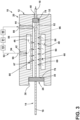
- FIG. 3 illustrates a schematic sectional view of the housing 12 and POL tile 14 after insertion.
- the coating 25 is not illustrated in FIG. 3 . It will be understood that any portion of the POL tile 14 can include the dielectric coating 25.
- the housing 12 further includes a second slot 40 through the outer wall 34 extending to the interior 36.
- the second slot 40 is in registry with the first insertion slot 38 though this need not be the case.
- the first end 16 of the POL tile 14 is positioned adjacent the first insertion slot 38.
- the second end 18 of the POL tile 14 is positioned adjacent the second slot 40. In this manner, the second end 18 can be received by or extend through the second slot 40, for example to provide for external access to the pinout connector 26 ( FIG. 1 ).
- the second end 18 can remain within the housing 12 when the POL tile is inserted through the first insertion slot 38, with no additional slot required.
- the housing 12 can provide for liquid impingement cooling of the POL tile 14. More specifically, the outer wall 34 of the housing 12 can define at least one fluid inlet 42 and a fluid outlet 44. Multiple fluid inlets 42 and multiple fluid outlets 44 can be provided, though this need not be the case.
- a first fluid channel 46 and a second fluid channel 48 can be located within the housing 12 and fluidly coupled to the fluid inlet 42.
- a central component chamber 52 in the form of an impingement chamber can be positioned between the first fluid channel 46 and second fluid channel 48 and be fluidly coupled to the fluid outlet 44.
- a first interior wall 56 divides the first fluid channel 46 from the component chamber 52.
- a second interior wall 58 divides the second fluid channel 48 from the component chamber 52. In this manner, the first interior wall 56 can form a first side of the component chamber 52, and the second interior wall 58 can form a second side of the component chamber 52.
- a first impingement sprayer 66 and a second impingement sprayer 68 direct an impingement flow onto the POL tile 14.
- the impingement sprayers can be located on opposite sides of the POL tile 14 or on opposite sides of the component chamber 52.
- one possible implementation is to incorporate the impingement sprayers 66, 68 into the respective first interior wall 56 and second interior wall 58.
- the first impingement sprayer 66 is in the form of a first set of impingement holes 67 extending through the first interior wall 56
- the second impingement sprayer 68 is in the form of a second set of impingement holes 69 extending through the second interior wall 58.
- the impingement sprayers 66, 68 can have any suitable form, including circular holes, rectangular slots, jet nozzles, showerhead nozzles, or the like, in non-limiting examples.
- either or both of the impingement sprayers 66, 68 can include a sprayer body or nozzle coupled to a liquid supply line.
- Either or both of the first impingement sprayer 66 or the second impingement sprayer 68 can also fluidly couple the respective first fluid channel 46 and second fluid channel 48 to the component chamber 52 as shown. In this manner, the first interior wall 56 and the second interior wall 58 can at least partially define the component chamber 52.
- any number of impingement sprayers can be provided.
- any number of impingement holes can be provided in the first set of impingement holes 67 and the second set of impingement holes 69.
- the first set of impingement holes 67 contains fewer impingement holes than the second set of impingement holes 69 though this need not be the case.
- the POL tile 14 can have discrete or localized heated regions or "hot spots" during operation. In such a case, a cluster of impingement sprayers or holes can be positioned adjacent to or confronting such regions to provide for localized impingement cooling. The number and positioning of impingement sprayers can be tailored to the power overlay tile for improved cooling and efficiency.
- the relative size, positioning, and arrangement of impingement sprayers can be adjusted or tailored based on a rate of fluid flow through the liquid supply line.
- the supply line and impingement sprayers can be configured to provide a fluid velocity or jet velocity through the impingement sprayers of between 0.1 m/s and 1 m/s, or between 1 m/s and 3 m/s, or greater than 3 m/s.
- the sealing element 28 can abut or contact a corresponding inner surface or interior surface of the housing 12.
- the first seal 30 abuts a first surface 76 adjacent the first insertion slot 38
- the second seal 32 abuts a second surface 78 adjacent the second slot 40 though this need not be the case.
- the sealing element 28 can provide for fluid sealing of the impingement chamber 52 and prevent leakage through the first insertion slot 38 or second slot 40. In this manner, the first interior wall 56, the second interior wall, or the sealing element 28 can at least partially define the component chamber 52.
- heat can be generated by the set of electrical devices 24 on the POL tile 14.
- Liquid coolant 90 such as water, water-ethylene glycol, oil, or dielectric fluid can flow into the housing 12 by the fluid inlet 42.
- water can be used for the liquid coolant 90 while maintaining electrical insulation of components in the POL tile 14.
- the liquid coolant 90 can enter the first fluid channel 46 and second fluid channel 48, flow through the first and second impingement sprayers 66, 68, and impinge upon opposing sides of the POL tile within the chamber 52 before exiting the housing 12 through the fluid outlet 44.
- a liquid coolant circuit 92 can pass through the housing 12 from the fluid inlet 42, to at least one of the first fluid channel 46 or the second fluid channel 48, to at least one of the first impingement sprayer 66 or the second impingement sprayer 68, to the component chamber 52, and to the fluid outlet 44.
- a supply line 94 can be at least partially defined by the fluid inlet 42 and one or both impingement sprayers 66, 68.
- a return line 96 can be at least partially defined by the component chamber 52 and fluid outlet 44.
- the supply line 94 and return line 96 can at least partially form the liquid coolant circuit 92.
- the housing 12 can provide for at least double-sided liquid impingement cooling of the POL tile 14 inserted therein.
- the liquid coolant 90 can be recirculated between the return line 96 and supply line 94.
- the liquid coolant 90 can be drawn from a reservoir 91 by a pump 93.
- the pump 93 can direct the liquid coolant 90 to the supply line 94 for impingement cooling of the POL tile 14.
- the return line 96 can direct the liquid coolant 90 out of the housing 12 to a heat exchanger 95 or other cooling mechanism for removing excess heat contained in the coolant from the POL tile 14.
- the reduced-temperature liquid coolant 90 can then be directed back to the supply line 94 for further or continued impingement cooling of the POL tile 14 within the housing 12.
- the reservoir 91, pump 93, and heat exchanger 95 are illustrated along a common portion of the liquid coolant circuit 92 for visual clarity. It will be understood that the liquid coolant circuit 92 can include other portions, branches, or the like, as well as other components such as valves, switches, or the like, as is known in the art.
- multiple modular units 20 can be fluidly coupled together between corresponding fluid inlets 42 and fluid outlets 44.
- the fluid outlet of a first modular unit can be coupled to a fluid inlet of a second modular unit, such that multiple modular units are fluidly coupled in series and share a common liquid coolant circuit.
- two modular units can be provided with fluidly separated liquid coolant circuits.
- a first modular unit can be provided with a first coolant
- a second modular unit can be provided with a second coolant.
- Such an arrangement could be utilized for cooling two distinct types of electronic components, such as a POL tile and a POL card in one non-limiting example.
- a first group of modular units can share a first liquid coolant circuit, e.g. with fluid inlets coupled to fluid outlets in series, while a second group of modular units share a second liquid coolant circuit.
- a single modular unit 20 can be provided with multiple liquid coolant circuits.
- the housing can include a first fluid inlet and a first fluid outlet, with a first liquid coolant circuit extending through the housing therebetween.
- the housing can also include a second fluid inlet and a second fluid outlet, with a second liquid coolant circuit extending through the housing therebetween.
- the first and second liquid coolant circuits can carry the same or different liquid coolants.
- the first liquid coolant circuit is fluidly coupled to one side of the electronic component
- the second liquid coolant circuit is fluidly coupled to another side of the electronic component.
- the first liquid coolant circuit impinges coolant at a first velocity onto the one side of the electronic component
- the second liquid coolant circuit impinges coolant at a second velocity onto the second side of the electronic component.
- the first liquid coolant circuit provides a first coolant, e.g. oil, to the one side of the electronic component
- the second liquid coolant circuit provides a second coolant, e.g. water, to the other side of the electronic component.
- the modular liquid-cooled assembly 10 can have one or multiple types of coolant supplied to each modular unit. It is also contemplated that the modular liquid-cooled assembly 10 can have one or multiple types of coolant supplied to each electronic component, such as a POL tile, contained therein. The one or multiple types of coolant can be tailored to each modular unit, or to each component chamber, based on cooling needs, performance, or other considerations.
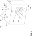
- FIG. 4 another liquid-cooled assembly 110 is illustrated.
- the assembly 110 is similar to the assembly 10; therefore, like parts will be described with like numerals increased by 100, with it being understood that the description of the like parts of the assembly 10 applies to the assembly 110, except where noted.
- the assembly 110 including a housing 112 with a fluid inlet 142 and a fluid outlet 144.
- the housing 112 includes multiple insertion slots 138 configured to receive multiple electronic components, for example multiple POL tiles.
- the housing 112 is configured to receive a first POL tile 114A and a second POL tile 114B (illustrated in dashed outline).
- the first POL tile 114A and second POL tile 114B can be received within the housing 112 in a stacked configuration. It will be understood that the housing 112 can accommodate any number of POL tiles, including a single POL tile, or three or more POL tiles.
- the POL tiles can be arranged in any suitable manner within the housing 112, including in a stacked configuration, a planar configuration, an annular configuration, or the like, or combinations thereof.
- multiple housings 112 can be provided and coupled together to form a modular power overlay assembly or arrangement. Such a modular power overlay assembly can also be formed extending in multiple directions.
- a liquid supply line 194 is illustrated entering the fluid inlet 142, and a liquid return line 196 is illustrated exiting the fluid outlet 144. It is also contemplated that coolant can be recirculated from the return line 196 to the supply line 194 as described above. Additionally or alternatively, a dielectric coating similar to the dielectric coating 25 can be provided on either or both of the first POL tile 114A and the second POL tile 114B, including on any portion thereof.
- FIG. 5 a cross-sectional view of the housing 112 along line V-V is illustrated with the first and second POL tiles 114A, 114B in position.
- the fluid inlet 142 is coupled to an interior inlet chamber 180 that can feed one or more fluid channels, illustrated as a first fluid channel 146, a second fluid channel 148, and a third fluid channel 150.
- a first POL tile 14A is inserted into a first component chamber 152
- a second POL tile 14B is inserted into a second component chamber 154.
- the first and second component chambers 152, 154 can fluidly couple to an interior outlet chamber 182.
- the interior outlet chamber 182 can fluidly couple to the fluid outlet 144.
- the housing 112 can include multiple interior walls dividing and forming the corresponding fluid channels and component chambers.
- a first interior wall 156 separates and at least partially defines the first fluid channel 146 and first component chamber 152.
- a second interior wall 158 separates and at least partially defines the second fluid channel 148 and the first component chamber 152.
- a third interior wall 160 separates and at least partially defines the second fluid channel 148 and the second component chamber 154.
- a fourth interior wall 162 separates and at least partially defines the third fluid channel 150 and the second component chamber 154. In this manner, the first and second interior walls 156, 158 form opposing sides of the first component chamber 152, and the third and fourth interior walls 160, 162 form opposing sides of the second component chamber 154.
- the fluid channels 146, 148, 150 and POL chambers 152, 154 are illustrated in a stacked configuration, any arrangement or positioning of interior walls, fluid channels, and component chambers can be utilized.
- the POL tiles can be received vertically within the housing such that cooling liquid impinges an upper portion of the POL tile and flows downward along the surface of the POL tile by gravity.
- the POL tiles can be positioned in multiple orientations within a common housing, including horizontally, vertically, diagonally, or the like, or combinations thereof.
- first impingement sprayer 166, second impingement sprayer 168, third impingement sprayer 170, and fourth impingement sprayer 172 can be provided for directing impingement flows onto either or both of the POL tiles 114A, 114B.
- one possible implementation is to incorporate the impingement sprayers 166, 168, 170, 172 in the respective first interior wall 156, second interior wall 158, third interior wall 160, and fourth interior wall 162.
- the impingement sprayers 166, 168, 170, 172 are each illustrated as including sets of impingement holes that can fluidly couple the corresponding fluid channel and POL chamber separated by each interior wall 156, 158, 160, 162.
- a liquid coolant circuit 192 passes through the housing 112 and includes a supply line 194 and return line 196. For visual clarity, coolant is not illustrated within the housing 112. It will be understood that liquid coolant can flow through the liquid coolant circuit 192 including the supply line 194 and return line 196.
- the supply line 194 of the illustrated example passes through the fluid inlet 142 to the inlet chamber 180, continues to the first fluid channel 146, second fluid channel 148, and third fluid channel 150, and enters the first impingement sprayer 166, second impingement sprayer 168, and third impingement sprayer 170.
- the return line 196 passes from the first component chamber 152 and second component chamber 154 to the outlet chamber 182 and to the fluid outlet 144.
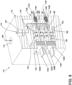
- FIG. 6 illustrates another cross-sectional view of the housing 112 along the line VI-VI ( FIG. 4 ) and illustrates the liquid coolant circuit 192 in an alternate perspective.
- a first sealing element 128A and a second sealing element 128B can be provided in the assembly 110.
- the first sealing element 128A is coupled to the first POL tile 114A
- a second sealing element 128B is coupled to the second POL tile 114B, though this need not be the case.
- either or both of the sealing elements 128A, 128B can be coupled directly to the housing 112.
- the first sealing element 128A of the illustrated example includes first seal 130A and second seal 132B, and the second sealing element 128B includes first seal 130B and second seal 132B as shown. More specifically, the first seals 130A, 130B are located proximate the respective first ends 116A, 116B, and the second seals 132A, 132B are located proximate the respective second ends 118A, 118B of the respective first and second POL tiles 114A, 114B. In this manner, the first and second sealing elements 128A, 128B can provide for fluid sealing of the corresponding first and second component chambers 152, 154.
- liquid coolant can flow through the liquid coolant circuit 192 through the supply line 194, entering the fluid inlet 142 and inlet chamber 180.
- the liquid coolant can then be directed into the first fluid channel 146, second fluid channel 148, and third fluid channel 150.
- the first and second sprayers 166, 168 can emit an impinging spray of liquid coolant onto opposing sides of the first POL tile 114A within the component chamber 152.
- the third and fourth impingement sprayers 170, 172 can emit an impinging spray of liquid coolant onto opposing sides of the POL tile 114B within the second component chamber 154, thereby removing heat from the POL tiles 114A, 114B during operation.
- the warmed coolant can be directed through the return line 196 to the outlet chamber 182 and exit the housing 112 via fluid outlet 144.
- FIG. 7 illustrates a method 200 of cooling an electronic component having a set of heat-generating components coupled to a substrate, such as the POL tiles 14, 114A, 114B.
- the method 200 begins at 202 by flowing liquid coolant 90 through a supply line 94, 194 to first and second impingement sprayers 66, 68, 166, 168, 170, 172 located on opposite sides of the electronic component, such as the POL tile 14, 114A, 114B.
- the method 200 includes emitting an impinging spray of the liquid coolant 90 from the first and second impingement sprayers 66, 68, 166, 168, 170, 172 onto at least two opposite surfaces of the electronic component, such as the POL tile 14, 114A, 114B, within the component chamber 52, 152, 154.
- the method includes directing the sprayed liquid coolant 90 out of the component chamber 52, 152, 154 through return line 96, 196 fluidly coupled to the component chamber 52, 152, 154.
- the method 200 includes directing the liquid coolant 90 into at least two fluid channels 46, 48, 146, 148, 150 within a housing 12, 112.
- the at least two fluid channels 46, 48, 146, 148, 150 can be positioned upstream of the impingement sprayers 66, 68, 166, 168, 170, 172.
- the method 200 includes flowing the liquid coolant 90 through a set of impingement holes 67, 69 in an interior wall 56, 58, 156, 158, 160, 162 of the housing 12, 112 into the component chamber 52, 152, 154, with the set of impingement holes 67, 69 at least partially defining the first and second impingement sprayers 66, 68, 166, 168, 170, 172.
- the method 200 includes flowing the liquid coolant 90 into an inlet chamber 180 upstream of the at least two fluid channels 46, 48, 146, 148, 150 and at least partially defining the supply line 94, 194.
- the method 200 includes directing the liquid coolant 90 from the component chamber 52, 152, 154 into a downstream outlet chamber 182 at least partially defining the return line 96, 196.
- the method 200 includes drawing the liquid coolant 90 into the housing 12, 112 carrying the electronic component, such as the POL tile 14, 114A, 114B by way of the fluid inlet 42, 142 at least partially forming the supply line 94, 194, and removing the liquid coolant 90 from the housing 12, 112, by way of the fluid outlet 44, 144 at least partially forming the return line 96, 196.
- the liquid coolant 90 can be drawn from an external reservoir in one non-limiting example.
- the method 200 includes recirculating the liquid coolant 90 from the return line 96, 196 back to the supply line 94, 194.
- the liquid-cooled assemblies described herein can include replaceable building blocks or tiles having a substantially similar underlying form factor (e.g. footprint, or common connections), that can provide low-cost manufacturability and interactive placement for a POL module assembly or other power module assembly. Common or reusable form factors can further result in higher process or manufacturing yields, and different module configuration without significant design changes.
- the assembly described provides for improved repairability, as a given power overlay tile can be easily removed, replaced, or serviced as needed.
- the sealed, modular housing provides for a compact, ultra-high-power density assembly of multiple devices into a power electronics system.
- the housing design described herein allows for replaceable or permanently installed and sealed power electronics devices.
- direct liquid impingement or spray provides for improved cooling of the power overlay tiles compared to traditional designs utilizing heat spreaders, conductive plates, or the like.
- Multiple sides of the power overlay tiles can be simultaneously cooled by direct liquid contact, including on opposing sides of the tiles, thereby reducing cooling time and improving performance of the power overlay assembly.
- the power overlay tile design further allows for the use of non-insulating cooling fluids (e.g. water) having better cooling performance compared to insulating fluids (e.g. oil), including in examples where an insulating coating is provided over the POL tiles.
- Direct contact, forced convection cooling on dual sides of a power electronics device provides for more efficient heat extraction on shorter timescales compared to traditional methods. Forced convection by way of jet impingement or spray further enhances this heat extraction with locally-higher heat transfer coefficients that may be targeted directly opposite each of the internal heat generating components.
- the sealed and modular housing as described herein allows for higher power density, three-dimensional configurations that are better suited to meet high power demands.
Landscapes
- Engineering & Computer Science (AREA)
- Microelectronics & Electronic Packaging (AREA)
- Physics & Mathematics (AREA)
- Thermal Sciences (AREA)
- Cooling Or The Like Of Semiconductors Or Solid State Devices (AREA)
Abstract
Description
- This invention was made with government support under Contract No. W911NF1820101 awarded by the United States Government. The government has certain rights in the invention.
- This application claims priority to
U.S. Patent Application No. 17/499,324, filed October 12, 2021 - The disclosure generally relates to electrical power module components, and more specifically toward a housing with structures for direct liquid cooling of power module components.
- Power systems manage the supplying of power from power sources, such as generators, to electrical loads. In one example, gas turbine engines are used for propulsion of aircraft, and typically provide mechanical power which ultimately powers a number of different accessories such as generators, starter/generators, permanent magnet alternators (PMA), fuel pumps, and hydraulic pumps, e.g., equipment for functions needed on an aircraft other than propulsion. For example, contemporary aircraft need electrical power for avionics, motors, and other electric equipment. A generator coupled with a gas turbine engine converts the mechanical power of the engine into electrical energy, which is distributed throughout the aircraft by electrically-coupled nodes of the power distribution system. In addition, the electrical components within such power systems can generate significant amounts of heat during operation, and various mechanisms exist for cooling such systems including heat spreaders, heat exchangers, or the like.
- Aspects and advantages of the disclosure will be set forth in part in the following description, or may be obvious from the description, or may be learned through practice of the disclosure herein.
- In one aspect, the disclosure relates to a liquid-cooled assembly for an electronic component. The assembly includes a housing defining at least one component chamber having an insertion slot provided on an exterior of the housing, a first impingement sprayer located on a first side of the component chamber, a second impingement sprayer located on a second side of the component chamber, an inlet on the housing fluidly coupled to the impingement sprayers, an outlet on the housing fluidly coupled to the component chamber, and a liquid coolant circuit passing through the housing from the inlet, through at least one of the first impingement sprayer or the second impingement sprayer, through the component chamber, and to the outlet.
- In another aspect, the disclosure relates to a method of cooling an electronic component having a set of heat-generating components coupled to a substrate. The method includes flowing liquid coolant through a supply line to first and second impingement sprayers located on opposite sides of the electronic component, emitting an impinging spray of the liquid coolant from the first and second impingement sprayers onto at least two opposite surfaces of the electronic component within a component chamber, and directing the sprayed liquid coolant out of the component chamber through a return line fluidly coupled to the component chamber.
- These and other features, aspects and advantages of the disclosure will become better understood with reference to the following description and appended claims. The accompanying drawings, which are incorporated in and constitute a part of this specification, illustrate the disclosure and, together with the description, serve to explain the principles of the disclosure herein.
- A full and enabling disclosure, including the best mode thereof, directed to one of ordinary skill in the art, is set forth in the specification, which makes reference to the appended figures in which:
-
FIG. 1 is a schematic perspective view of a modular liquid-cooled assembly for an electronic component in the form of a power overlay (POL) tile in accordance with various aspects described herein. -
FIG. 2 is a schematic perspective view of one modular unit in the assembly ofFIG. 1 . -
FIG. 3 is a schematic cross-sectional view of the modular unit ofFIG. 2 along the line III-III. -
FIG. 4 is a perspective view of another modular liquid-cooled assembly for an electronic component in accordance with various aspects described herein. -
FIG. 5 is a cross-sectional view of the assembly ofFIG. 4 along line V-V. -
FIG. 6 is a cross-sectional view of the assembly ofFIG. 4 along line VI-VI. -
FIG. 7 is a flowchart illustrating a method of cooling an electronic component in accordance with various aspects described herein. - Aspects of the present disclosure are directed to an electrical power assembly or an electrical power architecture. For the purposes of illustration, the present disclosure will be described in one exemplary environment of an aircraft power system. It will be understood that aspects of the disclosure can have general applicability to any power system, as well as in non-aircraft applications, such as other mobile applications and non-mobile industrial, commercial, and residential applications.
- Typical power electronics device chips are generally interconnected with fragile wire or ribbon bonding that extends above the device surface on one side and restricts the main heat extraction path from the chips to the other side of the device. Conventional wire or ribbon bonded devices do not allow for easy double-sided cooling or stacking of the power modules. This results in two-dimensional or planar "tiled" device configurations that attach to a separate planar cold plate. Such cold plates have additional thermal resistances in the heat transfer path and have lower thermal performance relative to direct contact forced convection on the device itself.
- In addition, cooling fluid performance varies for different types of fluids. Electrically insulating cooling fluids (e.g. oil) generally have lower thermal performance for a given pumping power compared to other, less-insulative cooling fluids (e.g. water) for direct contact cooling.
- Aspects of the disclosure enable an apparatus and method for power electronic device cooling by direct liquid impingement on multiple sides of the device. In one non-limiting example, electronic components such as power overlay (POL) tiles are fabricated with a wirebondless configuration that results in a compact, planar form factor. Such POL tiles are inserted into a housing that provides direct contact or impingement jets of cooling liquid located directly adjacent portions of the POL tiles requiring cooling, such as silicon carbide (SiC) chips, bus bars, or the like. The housing includes leak-tight feedthroughs into which the POL tiles can be inserted and electrical connections made to other devices. These and other aspects of the disclosure will be described herein in further detail.
- All directional references (e.g., radial, axial, upper, lower, upward, downward, left, right, lateral, front, back, top, bottom, above, below, vertical, horizontal, clockwise, counterclockwise) are only used for identification purposes to aid the reader's understanding of the disclosure, and do not create limitations, particularly as to the position, orientation, or use thereof. Connection references (e.g., attached, coupled, connected, and joined) are to be construed broadly and can include intermediate members between a collection of elements and relative movement between elements unless otherwise indicated. As such, connection references do not necessarily infer that two elements are directly connected and in fixed relation to each other. In non-limiting examples, connections or disconnections can be selectively configured to provide, enable, disable, or the like, an electrical connection between respective elements.
- While "a set of' various elements will be described, it will be understood that "a set" can include any number of the respective elements, including only one element. Additionally, while terms such as "voltage," "current," and "power" can be used herein, it will be evident to one skilled in the art that these terms can be interchangeable when describing aspects of an electrical circuit or circuit operations.
- The disclosure can be implemented in any electrical circuit environment having a switch. One non-limiting example of an electrical circuit environment that can include aspects of the disclosure can include an aircraft power system architecture, which enables production of electrical power from at least one spool of a turbine engine, such as a gas turbine engine, and delivers the electrical power to a set of electrical loads via at least one solid state switch, such as a solid state power controller (SSPC) switching device. One non-limiting example of the SSPC can include metal-oxide-semiconductor field-effect transistor (MOSFET), such as a silicon carbide (SiC) or Gallium Nitride (GaN) based, high power switch. SiC or GaN can be selected based on their solid state material construction, their ability to handle high voltages and large power levels in smaller and lighter form factors, and their high speed switching ability to perform electrical operations very quickly. Additional switching devices or additional silicon-based power switches can be included.
- As used herein, a "system" or a "controller module" can include at least one processor and memory. Non-limiting examples of the memory can include Random Access Memory (RAM), Read-Only Memory (ROM), flash memory, or one or more different types of portable electronic memory, such as discs, DVDs, CD-ROMs, etc., or any suitable combination of these types of memory. The processor can be configured to run any suitable programs or executable instructions designed to carry out various methods, functionality, processing tasks, calculations, or the like, to enable or achieve the technical operations or operations described herein.
- The exemplary drawings are for purposes of illustration only and the dimensions, positions, order and relative sizes reflected in the drawings attached hereto can vary.
-
FIG. 1 is a schematic illustration of one exemplary liquid-cooled assembly 10 (hereafter "assembly 10") for an electronic component in accordance with various aspects described herein. The electronic component will be described in the exemplary form of a power overlay (POL)tile 14. Aspects of the disclosure can be applied to any suitable electronic component, including a printed circuit board (PCB) card or a PCB tile in non-limiting examples. - The
assembly 10 includes multiple coupledhousings 12 carryingcorresponding POL tiles 14. In the example shown, onePOL tile 14 is positioned within a correspondinghousing 12 though this need not be the case. - Each
POL tile 14 extends from afirst end 16 to asecond end 18. ThePOL tiles 14 can be supplied with power at thesecond end 18, for example via a generator, bus, or other power source, and can switchably deliver the supplied power to connected devices via thefirst end 16. In contrast to conventional devices utilizing multiple wire bonds for device attachment, it is contemplated that thePOL tiles 14 can include a wirebondless architecture wherein direct connection is enabled to reduce inductance, improve device switching performance, or decrease device switching times. Particular details of thePOL tiles 14 will not be described except where needed to improve clarity or understanding of the present disclosure. - The
assembly 10 can be in the form of a modular assembly. In the example shown, onehousing 12 and onePOL tile 14 collectively define amodular unit 20. Additionally or alternatively, amodular unit 20 can be defined by asingle housing 12 receivingmultiple POL tiles 14. Eachmodular unit 20 can be fastened, stacked, or otherwise coupled together to extend in at least two directions, such as horizontally and vertically in a non-limiting example. In this manner, theassembly 10 can have multiple modular units coupled together and arranged along multiple directions to form a multi-dimensional liquid-cooled assembly with increased power density for meeting power demands. - In one non-limiting example, the liquid-cooled
assembly 10 can include one or more fluid connections 15 (illustrated schematically in dashed line). Any number offluid connections 15 can be utilized.Such fluid connections 15 can provide a fluid inlet to amodular unit 20, a fluid outlet to amodular unit 20, or a fluid coupling between twomodular units 20, in non-limiting examples. - Turning to
FIG. 2 , one exemplarymodular unit 20 withhousing 12 andPOL tile 14 is illustrated that can be utilized in theassembly 10. ThePOL tile 14 further includes asubstrate 22 carrying a set ofelectrical devices 24. The set ofelectrical devices 24 can include solid state switching devices, gate devices configured to operate the gates of the respective solid-state switching devices, rectifying components such as diodes, power storage devices such as batteries, or the like, or any combination thereof. Thesecond end 18 includes apinout connector 26 for connection to other electrical devices as needed. Optionally, an insulating ordielectric coating 25 can be provided on any portion of thePOL tile 14, including over the set ofelectrical devices 24, or over theentire POL tile 14. Such acoating 25 can include any suitable insulating material, including silicone or parylene in non-limiting examples. In the illustrated example, thecoating 25 is illustrated over a portion of thesubstrate 22 including the set ofelectrical devices 24 though this need not be the case. - A sealing
element 28 can be provided in theassembly 10. In the example shown, the sealingelement 28 is coupled to thePOL tile 14. Additionally or alternatively, the sealingelement 28 can be coupled to either or both of thehousing 12 or thePOL tile 14. In the example shown, includes afirst seal 30 proximate thefirst end 16 and asecond seal 32 proximate thesecond end 18 as shown. The sealingelement 28 can be formed of any suitable material including, but not limited to, rubber, silicone, dielectric materials, polymeric materials, composite materials, or fiberglass materials, or the like, or combinations thereof. In addition, while illustrated as including a pair of seals, the sealingelement 28 can include any number of seals, including only one, or three or more. In another non-limiting example, the sealingelement 28 can be formed as a unitary body coupled to thePOL tile 14 at multiple locations, such as a U-shaped sealing body coupled to thePOL tile 14 at distal ends thereof. Still further, while the sealingelement 28 is illustrated as a generally rectangular element, this is merely for the purposes of visual clarity and the design, size, or shape of the sealingelement 28 is not limited thereto. The sealingelement 28 can have any suitable geometric profile, as well as other components including locking mechanisms, fasteners, or the like, as is known in the art. - The
housing 12 includes anouter wall 34 bounding an interior 36. An aperture in the form of afirst insertion slot 38 extends through theouter wall 34 to the interior 36. The POL tile can be inserted into thehousing 12 through thefirst insertion slot 38 as shown. - Any suitable manufacturing method or process can be utilized in forming the
assembly 10, including casting, machining, or additive manufacturing. As used herein, "additive manufacturing" (AM) will refer to a process wherein the component is built layer-by-layer by successive deposition of material. AM is an appropriate name to describe the technologies that build 3D objects by adding layer-upon-layer of material, whether the material is plastic or metal. AM technologies can utilize a computer, 3D modeling software (Computer Aided Design or CAD), machine equipment, and layering material. Once a CAD sketch is produced, the AM equipment can read in data from the CAD file and lay down or add successive layers of liquid, powder, sheet material or other material, in a layer-upon-layer fashion to fabricate a 3D object. It should be understood that the term "additive manufacturing" encompasses many technologies including subsets like 3D Printing, Rapid Prototyping (RP), Direct Digital Manufacturing (DDM), layered manufacturing, and additive fabrication. Non-limiting examples of additive manufacturing that can be utilized to form an additively-manufactured component include powder bed fusion, vat photopolymerization, binder jetting, material extrusion, directed energy deposition, material jetting, or sheet lamination. -
FIG. 3 illustrates a schematic sectional view of thehousing 12 andPOL tile 14 after insertion. For visual clarity, thecoating 25 is not illustrated inFIG. 3 . It will be understood that any portion of thePOL tile 14 can include thedielectric coating 25. - The
housing 12 further includes asecond slot 40 through theouter wall 34 extending to the interior 36. In the illustrated example, thesecond slot 40 is in registry with thefirst insertion slot 38 though this need not be the case. Thefirst end 16 of thePOL tile 14 is positioned adjacent thefirst insertion slot 38. Thesecond end 18 of thePOL tile 14 is positioned adjacent thesecond slot 40. In this manner, thesecond end 18 can be received by or extend through thesecond slot 40, for example to provide for external access to the pinout connector 26 (FIG. 1 ). In another example, thesecond end 18 can remain within thehousing 12 when the POL tile is inserted through thefirst insertion slot 38, with no additional slot required. - It is further contemplated that the
housing 12 can provide for liquid impingement cooling of thePOL tile 14. More specifically, theouter wall 34 of thehousing 12 can define at least onefluid inlet 42 and afluid outlet 44. Multiplefluid inlets 42 and multiplefluid outlets 44 can be provided, though this need not be the case. Afirst fluid channel 46 and asecond fluid channel 48 can be located within thehousing 12 and fluidly coupled to thefluid inlet 42. Acentral component chamber 52 in the form of an impingement chamber can be positioned between thefirst fluid channel 46 and secondfluid channel 48 and be fluidly coupled to thefluid outlet 44. A firstinterior wall 56 divides thefirst fluid channel 46 from thecomponent chamber 52. A secondinterior wall 58 divides thesecond fluid channel 48 from thecomponent chamber 52. In this manner, the firstinterior wall 56 can form a first side of thecomponent chamber 52, and the secondinterior wall 58 can form a second side of thecomponent chamber 52. - A
first impingement sprayer 66 and asecond impingement sprayer 68 direct an impingement flow onto thePOL tile 14. The impingement sprayers can be located on opposite sides of thePOL tile 14 or on opposite sides of thecomponent chamber 52. As illustrated, one possible implementation is to incorporate theimpingement sprayers interior wall 56 and secondinterior wall 58. In the example shown, thefirst impingement sprayer 66 is in the form of a first set of impingement holes 67 extending through the firstinterior wall 56, and thesecond impingement sprayer 68 is in the form of a second set of impingement holes 69 extending through the secondinterior wall 58. The impingement sprayers 66, 68 can have any suitable form, including circular holes, rectangular slots, jet nozzles, showerhead nozzles, or the like, in non-limiting examples. In another non-limiting example, either or both of theimpingement sprayers first impingement sprayer 66 or thesecond impingement sprayer 68 can also fluidly couple the respective firstfluid channel 46 and secondfluid channel 48 to thecomponent chamber 52 as shown. In this manner, the firstinterior wall 56 and the secondinterior wall 58 can at least partially define thecomponent chamber 52. - Any number of impingement sprayers can be provided. In addition, any number of impingement holes can be provided in the first set of impingement holes 67 and the second set of impingement holes 69. In the example shown, the first set of impingement holes 67 contains fewer impingement holes than the second set of impingement holes 69 though this need not be the case. For example, the
POL tile 14 can have discrete or localized heated regions or "hot spots" during operation. In such a case, a cluster of impingement sprayers or holes can be positioned adjacent to or confronting such regions to provide for localized impingement cooling. The number and positioning of impingement sprayers can be tailored to the power overlay tile for improved cooling and efficiency. Furthermore, the relative size, positioning, and arrangement of impingement sprayers can be adjusted or tailored based on a rate of fluid flow through the liquid supply line. In one non-limiting example, the supply line and impingement sprayers can be configured to provide a fluid velocity or jet velocity through the impingement sprayers of between 0.1 m/s and 1 m/s, or between 1 m/s and 3 m/s, or greater than 3 m/s. - When the
POL tile 14 is inserted into thePOL chamber 52, the sealingelement 28 can abut or contact a corresponding inner surface or interior surface of thehousing 12. In the illustrated example, thefirst seal 30 abuts afirst surface 76 adjacent thefirst insertion slot 38, and thesecond seal 32 abuts asecond surface 78 adjacent thesecond slot 40 though this need not be the case. The sealingelement 28 can provide for fluid sealing of theimpingement chamber 52 and prevent leakage through thefirst insertion slot 38 orsecond slot 40. In this manner, the firstinterior wall 56, the second interior wall, or the sealingelement 28 can at least partially define thecomponent chamber 52. - With general reference to
FIGS. 1-3 , during operation, heat can be generated by the set ofelectrical devices 24 on thePOL tile 14.Liquid coolant 90 such as water, water-ethylene glycol, oil, or dielectric fluid can flow into thehousing 12 by thefluid inlet 42. In a non-limiting example where thePOL tile 14 includes thedielectric coating 25, water can be used for theliquid coolant 90 while maintaining electrical insulation of components in thePOL tile 14. - More specifically, the
liquid coolant 90 can enter thefirst fluid channel 46 and secondfluid channel 48, flow through the first andsecond impingement sprayers chamber 52 before exiting thehousing 12 through thefluid outlet 44. In this manner, aliquid coolant circuit 92 can pass through thehousing 12 from thefluid inlet 42, to at least one of thefirst fluid channel 46 or thesecond fluid channel 48, to at least one of thefirst impingement sprayer 66 or thesecond impingement sprayer 68, to thecomponent chamber 52, and to thefluid outlet 44. Asupply line 94 can be at least partially defined by thefluid inlet 42 and one or bothimpingement sprayers return line 96 can be at least partially defined by thecomponent chamber 52 andfluid outlet 44. Thesupply line 94 and returnline 96 can at least partially form theliquid coolant circuit 92. In this manner, thehousing 12 can provide for at least double-sided liquid impingement cooling of thePOL tile 14 inserted therein. - It is also contemplated that, in one possible implementation, the
liquid coolant 90 can be recirculated between thereturn line 96 andsupply line 94. In the illustrated example, theliquid coolant 90 can be drawn from areservoir 91 by apump 93. Thepump 93 can direct theliquid coolant 90 to thesupply line 94 for impingement cooling of thePOL tile 14. Thereturn line 96 can direct theliquid coolant 90 out of thehousing 12 to aheat exchanger 95 or other cooling mechanism for removing excess heat contained in the coolant from thePOL tile 14. The reduced-temperature liquid coolant 90 can then be directed back to thesupply line 94 for further or continued impingement cooling of thePOL tile 14 within thehousing 12. Thereservoir 91, pump 93, andheat exchanger 95 are illustrated along a common portion of theliquid coolant circuit 92 for visual clarity. It will be understood that theliquid coolant circuit 92 can include other portions, branches, or the like, as well as other components such as valves, switches, or the like, as is known in the art. - Some additional non-limiting examples or implementations of the
assembly 10 andmodular units 20 will be described below. It will be understood that such examples are given for illustrative purposes. - In one exemplary implementation, multiple
modular units 20 can be fluidly coupled together between correspondingfluid inlets 42 andfluid outlets 44. In one example, the fluid outlet of a first modular unit can be coupled to a fluid inlet of a second modular unit, such that multiple modular units are fluidly coupled in series and share a common liquid coolant circuit. - In another exemplary implementation, two modular units can be provided with fluidly separated liquid coolant circuits. For example, a first modular unit can be provided with a first coolant, and a second modular unit can be provided with a second coolant. Such an arrangement could be utilized for cooling two distinct types of electronic components, such as a POL tile and a POL card in one non-limiting example.
- In another exemplary implementation, a first group of modular units can share a first liquid coolant circuit, e.g. with fluid inlets coupled to fluid outlets in series, while a second group of modular units share a second liquid coolant circuit.
- In another exemplary implementation, a single
modular unit 20 can be provided with multiple liquid coolant circuits. For example, the housing can include a first fluid inlet and a first fluid outlet, with a first liquid coolant circuit extending through the housing therebetween. The housing can also include a second fluid inlet and a second fluid outlet, with a second liquid coolant circuit extending through the housing therebetween. The first and second liquid coolant circuits can carry the same or different liquid coolants. In one example, the first liquid coolant circuit is fluidly coupled to one side of the electronic component, and the second liquid coolant circuit is fluidly coupled to another side of the electronic component. In one example, the first liquid coolant circuit impinges coolant at a first velocity onto the one side of the electronic component, and the second liquid coolant circuit impinges coolant at a second velocity onto the second side of the electronic component. In one example, the first liquid coolant circuit provides a first coolant, e.g. oil, to the one side of the electronic component, and the second liquid coolant circuit provides a second coolant, e.g. water, to the other side of the electronic component. - It is contemplated that the modular liquid-cooled
assembly 10 can have one or multiple types of coolant supplied to each modular unit. It is also contemplated that the modular liquid-cooledassembly 10 can have one or multiple types of coolant supplied to each electronic component, such as a POL tile, contained therein. The one or multiple types of coolant can be tailored to each modular unit, or to each component chamber, based on cooling needs, performance, or other considerations. - Referring now to
FIG. 4 , another liquid-cooledassembly 110 is illustrated. Theassembly 110 is similar to theassembly 10; therefore, like parts will be described with like numerals increased by 100, with it being understood that the description of the like parts of theassembly 10 applies to theassembly 110, except where noted. - The
assembly 110 including ahousing 112 with afluid inlet 142 and afluid outlet 144. One difference compared to theassembly 10 is that thehousing 112 includesmultiple insertion slots 138 configured to receive multiple electronic components, for example multiple POL tiles. In the example shown, thehousing 112 is configured to receive afirst POL tile 114A and asecond POL tile 114B (illustrated in dashed outline). Thefirst POL tile 114A andsecond POL tile 114B can be received within thehousing 112 in a stacked configuration. It will be understood that thehousing 112 can accommodate any number of POL tiles, including a single POL tile, or three or more POL tiles. In addition, the POL tiles can be arranged in any suitable manner within thehousing 112, including in a stacked configuration, a planar configuration, an annular configuration, or the like, or combinations thereof. Furthermore,multiple housings 112 can be provided and coupled together to form a modular power overlay assembly or arrangement. Such a modular power overlay assembly can also be formed extending in multiple directions. - A
liquid supply line 194 is illustrated entering thefluid inlet 142, and aliquid return line 196 is illustrated exiting thefluid outlet 144. It is also contemplated that coolant can be recirculated from thereturn line 196 to thesupply line 194 as described above. Additionally or alternatively, a dielectric coating similar to thedielectric coating 25 can be provided on either or both of thefirst POL tile 114A and thesecond POL tile 114B, including on any portion thereof. - Turning to
FIG. 5 , a cross-sectional view of thehousing 112 along line V-V is illustrated with the first andsecond POL tiles fluid inlet 142 is coupled to aninterior inlet chamber 180 that can feed one or more fluid channels, illustrated as a firstfluid channel 146, a secondfluid channel 148, and a thirdfluid channel 150. A first POL tile 14A is inserted into afirst component chamber 152, and a second POL tile 14B is inserted into asecond component chamber 154. The first andsecond component chambers interior outlet chamber 182. Theinterior outlet chamber 182 can fluidly couple to thefluid outlet 144. - The
housing 112 can include multiple interior walls dividing and forming the corresponding fluid channels and component chambers. In the example shown, a firstinterior wall 156 separates and at least partially defines the firstfluid channel 146 andfirst component chamber 152. A secondinterior wall 158 separates and at least partially defines the secondfluid channel 148 and thefirst component chamber 152. A thirdinterior wall 160 separates and at least partially defines the secondfluid channel 148 and thesecond component chamber 154. A fourthinterior wall 162 separates and at least partially defines the thirdfluid channel 150 and thesecond component chamber 154. In this manner, the first and secondinterior walls first component chamber 152, and the third and fourthinterior walls second component chamber 154. - While the
fluid channels POL chambers - Furthermore, a
first impingement sprayer 166,second impingement sprayer 168,third impingement sprayer 170, andfourth impingement sprayer 172 can be provided for directing impingement flows onto either or both of thePOL tiles impingement sprayers interior wall 156, secondinterior wall 158, thirdinterior wall 160, and fourthinterior wall 162. The impingement sprayers 166, 168, 170, 172 are each illustrated as including sets of impingement holes that can fluidly couple the corresponding fluid channel and POL chamber separated by eachinterior wall - A
liquid coolant circuit 192 passes through thehousing 112 and includes asupply line 194 and returnline 196. For visual clarity, coolant is not illustrated within thehousing 112. It will be understood that liquid coolant can flow through theliquid coolant circuit 192 including thesupply line 194 and returnline 196. - In the illustrated example showing one possible implementation of the
liquid coolant circuit 192, thesupply line 194 of the illustrated example passes through thefluid inlet 142 to theinlet chamber 180, continues to the firstfluid channel 146, secondfluid channel 148, and thirdfluid channel 150, and enters thefirst impingement sprayer 166,second impingement sprayer 168, andthird impingement sprayer 170. Thereturn line 196 passes from thefirst component chamber 152 andsecond component chamber 154 to theoutlet chamber 182 and to thefluid outlet 144. -
FIG. 6 illustrates another cross-sectional view of thehousing 112 along the line VI-VI (FIG. 4 ) and illustrates theliquid coolant circuit 192 in an alternate perspective. Afirst sealing element 128A and asecond sealing element 128B can be provided in theassembly 110. In the example shown, thefirst sealing element 128A is coupled to thefirst POL tile 114A, and asecond sealing element 128B is coupled to thesecond POL tile 114B, though this need not be the case. In another non-limiting example, either or both of thesealing elements housing 112. - The
first sealing element 128A of the illustrated example includesfirst seal 130A andsecond seal 132B, and thesecond sealing element 128B includesfirst seal 130B andsecond seal 132B as shown. More specifically, thefirst seals second seals second POL tiles second sealing elements second component chambers - With general reference to
FIGS. 5-7 , liquid coolant can flow through theliquid coolant circuit 192 through thesupply line 194, entering thefluid inlet 142 andinlet chamber 180. The liquid coolant can then be directed into the firstfluid channel 146, secondfluid channel 148, and thirdfluid channel 150. The first andsecond sprayers first POL tile 114A within thecomponent chamber 152. The third andfourth impingement sprayers POL tile 114B within thesecond component chamber 154, thereby removing heat from thePOL tiles return line 196 to theoutlet chamber 182 and exit thehousing 112 viafluid outlet 144. -
FIG. 7 illustrates amethod 200 of cooling an electronic component having a set of heat-generating components coupled to a substrate, such as thePOL tiles method 200 begins at 202 by flowingliquid coolant 90 through asupply line second impingement sprayers POL tile method 200 includes emitting an impinging spray of theliquid coolant 90 from the first andsecond impingement sprayers POL tile component chamber liquid coolant 90 out of thecomponent chamber return line component chamber method 200 includes directing theliquid coolant 90 into at least twofluid channels housing 12, 112.The at least twofluid channels impingement sprayers method 200 includes flowing theliquid coolant 90 through a set of impingement holes 67, 69 in aninterior wall housing component chamber second impingement sprayers method 200 includes flowing theliquid coolant 90 into aninlet chamber 180 upstream of the at least twofluid channels supply line method 200 includes directing theliquid coolant 90 from thecomponent chamber downstream outlet chamber 182 at least partially defining thereturn line method 200 includes drawing theliquid coolant 90 into thehousing POL tile fluid inlet supply line liquid coolant 90 from thehousing fluid outlet return line liquid coolant 90 can be drawn from an external reservoir in one non-limiting example. Optionally, themethod 200 includes recirculating theliquid coolant 90 from thereturn line supply line - Aspects of the disclosure provide for a variety of benefits. The liquid-cooled assemblies described herein can include replaceable building blocks or tiles having a substantially similar underlying form factor (e.g. footprint, or common connections), that can provide low-cost manufacturability and interactive placement for a POL module assembly or other power module assembly. Common or reusable form factors can further result in higher process or manufacturing yields, and different module configuration without significant design changes. In addition, the assembly described provides for improved repairability, as a given power overlay tile can be easily removed, replaced, or serviced as needed. The sealed, modular housing provides for a compact, ultra-high-power density assembly of multiple devices into a power electronics system. The housing design described herein allows for replaceable or permanently installed and sealed power electronics devices.
- The use of direct liquid impingement or spray provides for improved cooling of the power overlay tiles compared to traditional designs utilizing heat spreaders, conductive plates, or the like. Multiple sides of the power overlay tiles can be simultaneously cooled by direct liquid contact, including on opposing sides of the tiles, thereby reducing cooling time and improving performance of the power overlay assembly. In examples where a dielectric coating is utilized with the tile surface, the power overlay tile design further allows for the use of non-insulating cooling fluids (e.g. water) having better cooling performance compared to insulating fluids (e.g. oil), including in examples where an insulating coating is provided over the POL tiles.
- More compact and efficient cooling approaches are needed for future designs of power electronics systems with higher power densities. Direct contact, forced convection cooling on dual sides of a power electronics device provides for more efficient heat extraction on shorter timescales compared to traditional methods. Forced convection by way of jet impingement or spray further enhances this heat extraction with locally-higher heat transfer coefficients that may be targeted directly opposite each of the internal heat generating components. The sealed and modular housing as described herein allows for higher power density, three-dimensional configurations that are better suited to meet high power demands.
- Many other possible aspects and configurations in addition to that shown in the above figures are contemplated by the present disclosure.
- To the extent not already described, the different features and structures of the various aspects can be used in combination with each other as desired. That one feature is not illustrated in all of the aspects is not meant to be construed that it is not included, but is done for brevity of description. Thus, the various features of the different aspects can be mixed and matched as desired to form new aspects of the disclosure, whether or not the new aspects are expressly described. All combinations or permutations of features described herein are covered by this disclosure.
- This written description uses examples to disclose aspects of the disclosure, including the best mode, and also to enable any person skilled in the art to practice the aspects of the disclosure, including making and using any devices or systems and performing any incorporated methods. The patentable scope of the disclosure is defined by the claims, and can include other examples that occur to those skilled in the art. Such other examples are intended to be within the scope of the claims if they have structural elements that do not differ from the literal language of the claims, or if they include equivalent structural elements with insubstantial differences from the literal languages of the claims.
- Various characteristics, aspects and advantages of the present disclosure may also be embodied in any permutation of aspects of the disclosure, including but not limited to the following technical solutions as defined in the enumerated aspects:
- 1. A liquid-cooled assembly for an electronic component, the assembly comprising a housing defining at least one component chamber having an insertion slot provided on an exterior of the housing, a first impingement sprayer located on a first side of the component chamber, a second impingement sprayer located on a second side of the component chamber, an inlet on the housing fluidly coupled to the impingement sprayers, an outlet on the housing fluidly coupled to the component chamber, and a liquid coolant circuit passing through the housing from the inlet, through at least one of the first impingement sprayer or the second impingement sprayer, through the component chamber, and to the outlet.
- 2. The liquid-cooled assembly of claim 1, wherein the first impingement sprayer comprises a first set of impingement holes extending through a first interior wall of the housing.
- 3. The liquid-cooled assembly of any preceding clause, wherein the second impingement sprayer comprises a second set of impingement holes extending through a second interior wall of the housing.
- 4. The liquid-cooled assembly of any preceding clause, wherein the first set of impingement holes confronts the second set of impingement holes.
- 5. The liquid-cooled assembly of any preceding clause, wherein the first side of the component chamber is located opposite the second side of the component chamber.
- 6. The liquid-cooled assembly of any preceding clause, further comprising a sealing element located within the component chamber and abutting an inner surface of the housing to fluidly seal the component chamber.
- 7. The liquid-cooled assembly of any preceding clause, wherein the electronic component comprises a power overlay (POL) tile, and further comprising multiple component chambers in a stacked configuration within the housing and having multiple corresponding insertion slots configured to receive multiple corresponding POL tiles.
- 8. The liquid-cooled assembly of any preceding clause, wherein the housing, component chamber, first impingement sprayer, and second impingement sprayer at least partially define a modular unit.
- 9. The liquid-cooled assembly of any preceding clause, further comprising multiple modular units coupled together and arranged along at least two directions to form a multi-dimensional liquid-cooled assembly.
- 10. The liquid-cooled assembly of any preceding clause, further comprising a coolant within the liquid coolant circuit and comprising one of water, water-ethylene glycol, oil, or dielectric liquid.
- 11. The liquid-cooled assembly of any preceding clause, further comprising a second slot provided on the exterior of the housing and in registry with the insertion slot.
- 12. The liquid-cooled assembly of any preceding clause, wherein each of the insertion slot and the second slot are fluidly coupled to the component chamber.
- 13. The liquid-cooled assembly of any preceding clause, further comprising an insulating coating on at least a portion of the electronic component.
- 14. The liquid-cooled assembly of any preceding clause, wherein the insulating coating comprises a dielectric coating.
- 15. A method of cooling an electronic component having a set of heat-generating components coupled to a substrate, the method comprising flowing liquid coolant through a supply line to first and second impingement sprayers located on opposite sides of the electronic component, emitting an impinging spray of the liquid coolant from the sprayers onto at least two opposite surfaces of the electronic component within a component chamber, and directing the sprayed liquid coolant out of the component chamber through a return line fluidly coupled to the component chamber.
- 16. The method of any preceding clause, further comprising directing the liquid coolant into at least two fluid channels within a housing, with the at least two fluid channels positioned upstream of the set of impingement sprayers.
- 17. The method of any preceding clause, further comprising flowing the liquid coolant through a set of impingement holes in an interior wall of the housing into the component chamber, with the set of impingement holes at least partially defining the set of impingement sprayers.
- 18. The method of any preceding clause, further comprising flowing the liquid coolant into an inlet chamber upstream of the at least two fluid channels and at least partially defining the supply line.
- 19. The method of any preceding clause, further comprising directing the liquid coolant from the component chamber into a downstream outlet chamber at least partially defining the return line.
- 20. The method of any preceding clause, further comprising drawing the liquid coolant into a housing carrying the electronic component by way of a housing inlet at least partially forming the supply line.
- 21. The method of any preceding clause, further comprising removing the liquid coolant from the housing by way of a housing outlet at least partially forming the return line.
- 22. The method of any preceding clause, further comprising recirculating the liquid coolant from the return line back to the supply line.
Claims (14)
- A liquid-cooled assembly (10, 110) for an electronic component (14, 24, 114A, 114B), the assembly (10, 110) comprising:a housing (12, 112) defining at least one component chamber (52, 152, 154) having an insertion slot (38, 40, 138) provided on an exterior of the housing (12, 112);a first impingement sprayer (66, 68, 166, 168, 170) located on a first side of the component chamber (52, 152, 154);a second impingement sprayer (66, 68, 166, 168, 170) located on a second side of the component chamber (52, 152, 154);an inlet (42, 142) on the housing (12, 112) fluidly coupled to the first impingement sprayer (66, 68, 166, 168, 170) and the second impingement sprayer (66, 68, 166, 168, 170);an outlet (44, 144) on the housing (12, 112) fluidly coupled to the component chamber (52, 152, 154); anda liquid coolant circuit (92, 192) passing through the housing (12, 112) from the inlet (42, 142), through at least one of the first impingement sprayer (66, 68, 166, 168, 170) or the second impingement sprayer (66, 68, 166, 168, 170), through the component chamber (52, 152, 154), and to the outlet (44, 144).
- The liquid-cooled assembly (10, 110) of claim 1, wherein the first impingement sprayer (66, 68, 166, 168, 170) comprises a first set of impingement holes (67, 69) extending through a first interior wall (56, 58, 156, 158, 160, 162) of the housing (12, 112).
- The liquid-cooled assembly (10, 110) of claim 2, wherein the second impingement sprayer (66, 68, 166, 168, 170) comprises a second set of impingement holes (67, 69) extending through a second interior wall (56, 58, 156, 158, 160, 162) of the housing (12, 112).
- The liquid-cooled assembly (10, 110) of any of claims 2-3, wherein the first set of impingement holes (67, 69) confronts the second set of impingement holes (67, 69).
- The liquid-cooled assembly (10, 110) of any of claims 1-4, wherein the first side of the component chamber (52, 152, 154) is located opposite the second side of the component chamber (52, 152, 154).
- The liquid-cooled assembly (10, 110) of any of claims 1-5, further comprising a sealing element (28, 30, 32, 128A, 128B, 130A, 130B, 132A, 132B) located within the component chamber (52, 152, 154) and abutting an inner surface (76, 78) of the housing (12, 112) to fluidly seal the component chamber (52, 152, 154).
- The liquid-cooled assembly (10, 110) of any of claims 1-6, wherein the electronic component (14, 24, 114A, 114B) comprises a power overlay (POL) tile (14, 114A, 114B), and further comprising multiple component chambers (52, 152, 154) in a stacked configuration within the housing (12, 112).
- The liquid-cooled assembly (10, 110) of claim 7, wherein the multiple component chambers (52, 152, 154) have multiple corresponding insertion slots (38, 40, 138) configured to receive multiple corresponding POL tiles (14, 114A, 114B).
- The liquid-cooled assembly (10, 110) of any of claims 1-8, wherein the housing (12, 112), component chamber (52, 152, 154), first impingement sprayer (66, 68, 166, 168, 170), and second impingement sprayer (66, 68, 166, 168, 170) at least partially define a modular unit (20).
- The liquid-cooled assembly (10, 110) of claim 9, further comprising multiple modular units (20) coupled together and arranged along at least two directions to form a multi-dimensional liquid-cooled assembly (10, 110).
- The liquid-cooled assembly (10, 110) of any of claims 1-10, further comprising a coolant (90) within the liquid coolant circuit (92, 192) and comprising one of water, water-ethylene glycol, oil, or dielectric liquid.
- The liquid-cooled assembly (10, 110) of any of claims 1-11, further comprising a second slot (38, 40, 138) provided on the exterior of the housing (12, 112) and in registry with the insertion slot (38, 40, 138).
- The liquid-cooled assembly (10, 110) of claim 12, wherein the second slot (38, 40, 138) is configured to receive a second end (18, 118A, 118B) of the electronic component (14, 24, 114A, 114B).
- The liquid-cooled assembly (10, 110) of any of claims 12-13, wherein each of the insertion slot (38, 40, 138) and the second slot (38, 40, 138) are fluidly coupled to the component chamber (52, 152, 154).
Applications Claiming Priority (1)
| Application Number | Priority Date | Filing Date | Title |
|---|---|---|---|
| US17/499,324 US11950394B2 (en) | 2021-10-12 | 2021-10-12 | Liquid-cooled assembly and method |
Publications (1)
| Publication Number | Publication Date |
|---|---|
| EP4167698A1 true EP4167698A1 (en) | 2023-04-19 |
Family
ID=82850630
Family Applications (1)
| Application Number | Title | Priority Date | Filing Date |
|---|---|---|---|
| EP22185634.7A Pending EP4167698A1 (en) | 2021-10-12 | 2022-07-19 | Liquid-cooled assembly and method |
Country Status (5)
| Country | Link |
|---|---|
| US (1) | US11950394B2 (en) |
| EP (1) | EP4167698A1 (en) |
| JP (1) | JP7378551B2 (en) |
| KR (1) | KR102792141B1 (en) |
| CN (1) | CN115968164A (en) |
Families Citing this family (4)
| Publication number | Priority date | Publication date | Assignee | Title |
|---|---|---|---|---|
| US12004332B2 (en) * | 2021-01-14 | 2024-06-04 | Alliance For Sustainable Energy, Llc | Cooling automotive power electronics |
| US12610820B2 (en) * | 2022-09-19 | 2026-04-21 | Pc Krause And Associates, Inc. | Power module thermal management system |
| WO2024197143A2 (en) * | 2023-03-21 | 2024-09-26 | Impact Cooling Inc. | System and method for cooling an electronic device |
| KR20250150919A (en) * | 2024-04-12 | 2025-10-21 | 삼성전자주식회사 | semiconductor device with liquid cooling structure |
Citations (3)
| Publication number | Priority date | Publication date | Assignee | Title |
|---|---|---|---|---|
| US5718117A (en) * | 1996-04-10 | 1998-02-17 | Motorola, Inc. | Apparatus and method for spray-cooling an electronic module |
| US5831824A (en) * | 1996-01-31 | 1998-11-03 | Motorola, Inc. | Apparatus for spray-cooling multiple electronic modules |
| US7477513B1 (en) * | 2006-12-29 | 2009-01-13 | Isothermal Systems Research, Inc. | Dual sided board thermal management system |
Family Cites Families (30)
| Publication number | Priority date | Publication date | Assignee | Title |
|---|---|---|---|---|
| US4912600A (en) * | 1988-09-07 | 1990-03-27 | Auburn Univ. Of The State Of Alabama | Integrated circuit packaging and cooling |
| DE10146558A1 (en) * | 2001-09-21 | 2003-04-30 | Siemens Ag | Power semiconductor module with one or more power semiconductor |
| JP2005228237A (en) | 2004-02-16 | 2005-08-25 | Hitachi Ltd | Liquid cooling system and electronic apparatus equipped with the same |
| US7971852B2 (en) * | 2005-02-02 | 2011-07-05 | Toyota Jidosha Kabushiki Kaisha | Seal structure of high-pressure tank |
| US7312987B1 (en) | 2005-12-09 | 2007-12-25 | Storage Technology Corporation | Adaptable thin plate modular heat exchanger blade for cooling electronic equipment |
| JP4699253B2 (en) | 2006-03-23 | 2011-06-08 | トヨタ自動車株式会社 | Cooler |
| DE102006041788B4 (en) | 2006-09-06 | 2012-06-14 | Airbus Operations Gmbh | An aircraft electronics cooling device for an aircraft with a liquid cooling system |
| JP2008198751A (en) | 2007-02-12 | 2008-08-28 | Denso Corp | Cooler and power conversion device using the same |
| US8358000B2 (en) | 2009-03-13 | 2013-01-22 | General Electric Company | Double side cooled power module with power overlay |
| IT1395698B1 (en) | 2009-05-28 | 2012-10-19 | Abb Spa | COOLING DEVICE FOR A SWITCH, AND SWITCH INCLUDING THIS DEVICE. |
| DE102009040197A1 (en) * | 2009-09-07 | 2011-03-10 | Behr Gmbh & Co. Kg | Modular battery construction |
| US8208258B2 (en) | 2009-09-09 | 2012-06-26 | International Business Machines Corporation | System and method for facilitating parallel cooling of liquid-cooled electronics racks |
| JP5273101B2 (en) | 2010-06-23 | 2013-08-28 | 株式会社デンソー | Semiconductor module and manufacturing method thereof |
| US8653635B2 (en) | 2011-08-16 | 2014-02-18 | General Electric Company | Power overlay structure with leadframe connections |
| US9337163B2 (en) | 2012-11-13 | 2016-05-10 | General Electric Company | Low profile surface mount package with isolated tab |
| US8872328B2 (en) | 2012-12-19 | 2014-10-28 | General Electric Company | Integrated power module package |
| US8987876B2 (en) | 2013-03-14 | 2015-03-24 | General Electric Company | Power overlay structure and method of making same |
| US9736967B2 (en) | 2013-08-07 | 2017-08-15 | Abb S.P.A. | Cooling apparatus for an electrical or electronic device, and electrical or electronic device, in particular a circuit breaker, comprising such cooling apparatus |
| US9209151B2 (en) | 2013-09-26 | 2015-12-08 | General Electric Company | Embedded semiconductor device package and method of manufacturing thereof |
| US20150092349A1 (en) | 2013-10-01 | 2015-04-02 | International Business Machines Corporation | Implementing redundant and high efficiency hybrid liquid and air cooling for chipstacks |
| JP6369004B2 (en) | 2013-10-22 | 2018-08-08 | 富士通株式会社 | Electronics |
| JP6075299B2 (en) | 2014-01-14 | 2017-02-08 | トヨタ自動車株式会社 | Cooler and its manufacturing method |
| US9437523B2 (en) * | 2014-05-30 | 2016-09-06 | Toyota Motor Engineering & Manufacturing North America, Inc. | Two-sided jet impingement assemblies and power electronics modules comprising the same |
| US10231364B2 (en) | 2016-10-24 | 2019-03-12 | Toyota Motor Engineering & Manufacturing North America, Inc. | Fluidly cooled power electronics assemblies having a thermo-electric generator |
| CN111095541B (en) * | 2017-09-06 | 2021-12-17 | 爱思欧托普集团有限公司 | Heat sink, heat sink device and module for liquid immersion cooling |
| CN108174574B (en) | 2017-12-13 | 2019-11-05 | 中国科学院电工研究所 | A kind of conducting liquid active cooling method and device |
| US10976119B2 (en) | 2018-07-30 | 2021-04-13 | The Boeing Company | Heat transfer devices and methods of transfering heat |
| US10985537B2 (en) * | 2018-09-14 | 2021-04-20 | Ge Aviation Systems Llc | Power overlay architecture |
| CN109637987B (en) * | 2018-11-15 | 2020-07-10 | 华中科技大学 | Immersed jet micro-jet direct liquid cooling heat dissipation device |
| US20220230938A1 (en) * | 2021-01-19 | 2022-07-21 | GM Global Technology Operations LLC | Power module with vascular jet impingement cooling system |
-
2021
- 2021-10-12 US US17/499,324 patent/US11950394B2/en active Active
-
2022
- 2022-07-19 EP EP22185634.7A patent/EP4167698A1/en active Pending
- 2022-08-10 JP JP2022128184A patent/JP7378551B2/en active Active
- 2022-08-11 CN CN202210959331.2A patent/CN115968164A/en active Pending
- 2022-08-12 KR KR1020220101233A patent/KR102792141B1/en active Active
Patent Citations (3)
| Publication number | Priority date | Publication date | Assignee | Title |
|---|---|---|---|---|
| US5831824A (en) * | 1996-01-31 | 1998-11-03 | Motorola, Inc. | Apparatus for spray-cooling multiple electronic modules |
| US5718117A (en) * | 1996-04-10 | 1998-02-17 | Motorola, Inc. | Apparatus and method for spray-cooling an electronic module |
| US7477513B1 (en) * | 2006-12-29 | 2009-01-13 | Isothermal Systems Research, Inc. | Dual sided board thermal management system |
Also Published As
| Publication number | Publication date |
|---|---|
| JP2023058004A (en) | 2023-04-24 |
| US11950394B2 (en) | 2024-04-02 |
| KR20230052214A (en) | 2023-04-19 |
| CN115968164A (en) | 2023-04-14 |
| US20230114057A1 (en) | 2023-04-13 |
| JP7378551B2 (en) | 2023-11-13 |
| KR102792141B1 (en) | 2025-04-04 |
Similar Documents
| Publication | Publication Date | Title |
|---|---|---|
| US11950394B2 (en) | Liquid-cooled assembly and method | |
| EP3832714B1 (en) | Cold plate assembly for an electronic component | |
| US9437523B2 (en) | Two-sided jet impingement assemblies and power electronics modules comprising the same | |
| CN106899215B (en) | Power conversion device | |
| JP5600097B2 (en) | Cold plate assembly and power electronics module | |
| US20120212907A1 (en) | Power electronics modules and power electronics module assemblies | |
| CN101901638B (en) | Busbar assembly, vehicle inverter module and method for cooling the inverter module | |
| CN110325018B (en) | Avionics cooling module | |
| EP3236725B1 (en) | Power electronics module | |
| US20170164516A1 (en) | Integrated Fluid Turbulator and Sealing System for Improved Thermal Management | |
| CN110944487A (en) | Cooling plate for power module | |
| US20190063848A1 (en) | Laminated microchannel heat exchangers | |
| KR20090124939A (en) | Heat treatment apparatus and method of manufacturing the apparatus | |
| WO2015087707A1 (en) | Drive module | |
| US11848129B1 (en) | Immersion-cooled inductors in DC-to-DC converters and methods of operating thereof | |
| WO2017020406A1 (en) | Cooling system of expandable inverter and mechanical assembly thereof | |
| CN114823578A (en) | Power module with pulse tube jet impingement cooling system | |
| US11872901B1 (en) | Charging electric vehicles using DC-to-DC converters with immersion-cooled inductors | |
| WO2017184635A1 (en) | Laminated microchannel heat exchangers | |
| KR102029098B1 (en) | Thermoelectric generation system installed in exhaust pipe | |
| US12322916B2 (en) | Electronic connection assembly | |
| CN102414535B (en) | Heat exchange device with stack of laminations and manufacturing method thereof | |
| US12051971B1 (en) | Compact high-power DC-to-DC converters with out-of-phase converter units and multiple cooling types | |
| US11950392B1 (en) | Liquid and air cooling of DC-to-DC converters and methods of operating thereof | |
| US20190393128A1 (en) | Cooler |
Legal Events
| Date | Code | Title | Description |
|---|---|---|---|
| PUAI | Public reference made under article 153(3) epc to a published international application that has entered the european phase |
Free format text: ORIGINAL CODE: 0009012 |
|
| STAA | Information on the status of an ep patent application or granted ep patent |
Free format text: STATUS: THE APPLICATION HAS BEEN PUBLISHED |
|
| AK | Designated contracting states |
Kind code of ref document: A1 Designated state(s): AL AT BE BG CH CY CZ DE DK EE ES FI FR GB GR HR HU IE IS IT LI LT LU LV MC MK MT NL NO PL PT RO RS SE SI SK SM TR |
|
| STAA | Information on the status of an ep patent application or granted ep patent |
Free format text: STATUS: REQUEST FOR EXAMINATION WAS MADE |
|
| 17P | Request for examination filed |
Effective date: 20231013 |
|
| RBV | Designated contracting states (corrected) |
Designated state(s): AL AT BE BG CH CY CZ DE DK EE ES FI FR GB GR HR HU IE IS IT LI LT LU LV MC MK MT NL NO PL PT RO RS SE SI SK SM TR |
|
| STAA | Information on the status of an ep patent application or granted ep patent |
Free format text: STATUS: EXAMINATION IS IN PROGRESS |
|
| 17Q | First examination report despatched |
Effective date: 20260122 |