EP4167668B1 - Verfahren zur bestimmung eines zellenplanungsschemas, vorrichtung, endgerät und netzwerkseitige vorrichtung - Google Patents
Verfahren zur bestimmung eines zellenplanungsschemas, vorrichtung, endgerät und netzwerkseitige vorrichtung Download PDFInfo
- Publication number
- EP4167668B1 EP4167668B1 EP21845442.9A EP21845442A EP4167668B1 EP 4167668 B1 EP4167668 B1 EP 4167668B1 EP 21845442 A EP21845442 A EP 21845442A EP 4167668 B1 EP4167668 B1 EP 4167668B1
- Authority
- EP
- European Patent Office
- Prior art keywords
- cell
- scheduling
- search space
- specific search
- bwp
- Prior art date
- Legal status (The legal status is an assumption and is not a legal conclusion. Google has not performed a legal analysis and makes no representation as to the accuracy of the status listed.)
- Active
Links
Images


Classifications
-
- H—ELECTRICITY
- H04—ELECTRIC COMMUNICATION TECHNIQUE
- H04W—WIRELESS COMMUNICATION NETWORKS
- H04W72/00—Local resource management
- H04W72/04—Wireless resource allocation
- H04W72/044—Wireless resource allocation based on the type of the allocated resource
- H04W72/0457—Variable allocation of band or rate
-
- H—ELECTRICITY
- H04—ELECTRIC COMMUNICATION TECHNIQUE
- H04L—TRANSMISSION OF DIGITAL INFORMATION, e.g. TELEGRAPHIC COMMUNICATION
- H04L5/00—Arrangements affording multiple use of the transmission path
- H04L5/0001—Arrangements for dividing the transmission path
- H04L5/0003—Two-dimensional division
- H04L5/0005—Time-frequency
- H04L5/0007—Time-frequency the frequencies being orthogonal, e.g. OFDM(A) or DMT
- H04L5/001—Time-frequency the frequencies being orthogonal, e.g. OFDM(A) or DMT the frequencies being arranged in component carriers
-
- H—ELECTRICITY
- H04—ELECTRIC COMMUNICATION TECHNIQUE
- H04L—TRANSMISSION OF DIGITAL INFORMATION, e.g. TELEGRAPHIC COMMUNICATION
- H04L5/00—Arrangements affording multiple use of the transmission path
- H04L5/003—Arrangements for allocating sub-channels of the transmission path
- H04L5/0053—Allocation of signalling, i.e. of overhead other than pilot signals
-
- H—ELECTRICITY
- H04—ELECTRIC COMMUNICATION TECHNIQUE
- H04L—TRANSMISSION OF DIGITAL INFORMATION, e.g. TELEGRAPHIC COMMUNICATION
- H04L5/00—Arrangements affording multiple use of the transmission path
- H04L5/0091—Signalling for the administration of the divided path, e.g. signalling of configuration information
- H04L5/0096—Indication of changes in allocation
-
- H—ELECTRICITY
- H04—ELECTRIC COMMUNICATION TECHNIQUE
- H04W—WIRELESS COMMUNICATION NETWORKS
- H04W72/00—Local resource management
- H04W72/12—Wireless traffic scheduling
-
- H—ELECTRICITY
- H04—ELECTRIC COMMUNICATION TECHNIQUE
- H04W—WIRELESS COMMUNICATION NETWORKS
- H04W72/00—Local resource management
- H04W72/12—Wireless traffic scheduling
- H04W72/1263—Mapping of traffic onto schedule, e.g. scheduled allocation or multiplexing of flows
-
- H—ELECTRICITY
- H04—ELECTRIC COMMUNICATION TECHNIQUE
- H04W—WIRELESS COMMUNICATION NETWORKS
- H04W72/00—Local resource management
- H04W72/12—Wireless traffic scheduling
- H04W72/1263—Mapping of traffic onto schedule, e.g. scheduled allocation or multiplexing of flows
- H04W72/1268—Mapping of traffic onto schedule, e.g. scheduled allocation or multiplexing of flows of uplink data flows
-
- H—ELECTRICITY
- H04—ELECTRIC COMMUNICATION TECHNIQUE
- H04W—WIRELESS COMMUNICATION NETWORKS
- H04W72/00—Local resource management
- H04W72/20—Control channels or signalling for resource management
- H04W72/23—Control channels or signalling for resource management in the downlink direction of a wireless link, i.e. towards a terminal
- H04W72/231—Control channels or signalling for resource management in the downlink direction of a wireless link, i.e. towards a terminal the control data signalling from the layers above the physical layer, e.g. RRC or MAC-CE signalling
-
- H—ELECTRICITY
- H04—ELECTRIC COMMUNICATION TECHNIQUE
- H04W—WIRELESS COMMUNICATION NETWORKS
- H04W72/00—Local resource management
- H04W72/20—Control channels or signalling for resource management
- H04W72/23—Control channels or signalling for resource management in the downlink direction of a wireless link, i.e. towards a terminal
- H04W72/232—Control channels or signalling for resource management in the downlink direction of a wireless link, i.e. towards a terminal the control data signalling from the physical layer, e.g. DCI signalling
-
- H—ELECTRICITY
- H04—ELECTRIC COMMUNICATION TECHNIQUE
- H04W—WIRELESS COMMUNICATION NETWORKS
- H04W72/00—Local resource management
- H04W72/50—Allocation or scheduling criteria for wireless resources
- H04W72/53—Allocation or scheduling criteria for wireless resources based on regulatory allocation policies
-
- H—ELECTRICITY
- H04—ELECTRIC COMMUNICATION TECHNIQUE
- H04W—WIRELESS COMMUNICATION NETWORKS
- H04W76/00—Connection management
- H04W76/20—Manipulation of established connections
-
- H—ELECTRICITY
- H04—ELECTRIC COMMUNICATION TECHNIQUE
- H04W—WIRELESS COMMUNICATION NETWORKS
- H04W88/00—Devices specially adapted for wireless communication networks, e.g. terminals, base stations or access point devices
- H04W88/08—Access point devices
-
- H—ELECTRICITY
- H04—ELECTRIC COMMUNICATION TECHNIQUE
- H04L—TRANSMISSION OF DIGITAL INFORMATION, e.g. TELEGRAPHIC COMMUNICATION
- H04L5/00—Arrangements affording multiple use of the transmission path
- H04L5/0001—Arrangements for dividing the transmission path
- H04L5/0014—Three-dimensional division
- H04L5/0023—Time-frequency-space
-
- H—ELECTRICITY
- H04—ELECTRIC COMMUNICATION TECHNIQUE
- H04L—TRANSMISSION OF DIGITAL INFORMATION, e.g. TELEGRAPHIC COMMUNICATION
- H04L5/00—Arrangements affording multiple use of the transmission path
- H04L5/0091—Signalling for the administration of the divided path, e.g. signalling of configuration information
- H04L5/0096—Indication of changes in allocation
- H04L5/0098—Signalling of the activation or deactivation of component carriers, subcarriers or frequency bands
-
- H—ELECTRICITY
- H04—ELECTRIC COMMUNICATION TECHNIQUE
- H04W—WIRELESS COMMUNICATION NETWORKS
- H04W72/00—Local resource management
- H04W72/20—Control channels or signalling for resource management
- H04W72/23—Control channels or signalling for resource management in the downlink direction of a wireless link, i.e. towards a terminal
-
- Y—GENERAL TAGGING OF NEW TECHNOLOGICAL DEVELOPMENTS; GENERAL TAGGING OF CROSS-SECTIONAL TECHNOLOGIES SPANNING OVER SEVERAL SECTIONS OF THE IPC; TECHNICAL SUBJECTS COVERED BY FORMER USPC CROSS-REFERENCE ART COLLECTIONS [XRACs] AND DIGESTS
- Y02—TECHNOLOGIES OR APPLICATIONS FOR MITIGATION OR ADAPTATION AGAINST CLIMATE CHANGE
- Y02D—CLIMATE CHANGE MITIGATION TECHNOLOGIES IN INFORMATION AND COMMUNICATION TECHNOLOGIES [ICT], I.E. INFORMATION AND COMMUNICATION TECHNOLOGIES AIMING AT THE REDUCTION OF THEIR OWN ENERGY USE
- Y02D30/00—Reducing energy consumption in communication networks
- Y02D30/70—Reducing energy consumption in communication networks in wireless communication networks
Definitions
- This application pertains to the field of wireless communication technologies, and specifically relates to a method and an apparatus for determining a cell scheduling mode, and a chip.
- 5G new radio (New Radio, NR) systems support carrier aggregation (Carrier Aggregation, CA), allowing configuration and activation of multiple carriers (Component Carrier, CC) or cells for user equipment (User Equipment, UE) and cross-carrier scheduling under CA.
- Carrier Aggregation Carrier Aggregation, CA
- CC Component Carrier
- UE User Equipment
- M-TRP Multiple Transmission and Reception Panel
- UE may be scheduled to perform data transmission and reception with multiple TRPs.
- both primary cells Primary Cells, Pcells
- secondary cells Secondary Cells, Scells
- Scells Secondary Cells
- Pcells primary cells
- Scells secondary cells
- an Scell is configured to be cross-carrier scheduled, it is necessary to configure an identifier of a serving cell (serving cell ID) scheduling the cell, and a carrier indicator field (Carrier Indicator Field, CIF for short) value for scheduling by the serving cell.
- serving cell ID serving cell
- CIF Carrier Indicator Field
- one cell can be scheduled by only one scheduling cell (meaning that one cell can only be scheduled by the cell itself or another cell).
- Pcells can only be self-scheduled.
- Pcells are generally deployed on low band carriers (carrier).
- carrier low band carriers
- low band carriers have insufficient bandwidth and have been mostly used for deployment of other technologies (for example, LTE).
- a solution to the problem of limited capacity of Pcell control channels may be configuring high band carriers (carrier) for Scells and using Scell to schedule Pcell, so as to reduce control channel PDCCH overheads.
- carrier carrier
- no specific scheme has been provided yet as to how a cell scheduling mode is determined for scheduling Pcell by Scell.
- a cross-carrier scheduling method includes: a network side device sending a high-layer signaling, the high-layer signaling being used for indicating that a primary cell supports cross-carrier scheduling by one or more secondary cells.
- D2 (“ Fast Scell activation and dormancy like behavior' by VIVO, 3GPP DRAFT; R1-1910242, published on 4 October 2019 ) discloses the discussion for fast Scell activation and dormancy like behavior.
- D2 provides some proposals respectively.
- proposal 1 support one of the following two options for fast Scell activation.
- Option1 support the following aperiodic TRS triggering mechanism; support standalone A-TRS which is not QCL-A with another periodic TRS on the same Scell; support more flexible "aperiodicTriggeringOffset" between the triggering DCI and the RS; support A-TRS transmission after the PUSCH triggered in the same UL grant.
- Option 2 support MAC CE triggering multiple TRS: in the triggering MAC CE, support to indicate the exact timing of each TRS, which is not QCL-A with another periodic TRS on the same Scell; send LS to RAN2 to specify such MAC CE.
- the objective of embodiments of this application is to provide a method and an apparatus for determining a cell scheduling mode, a terminal, and a network-side device, to determine a cell scheduling mode for scheduling Pcell by Scell.
- a method for determining a cell scheduling mode is provided, which is defined in claim 1.
- an apparatus for determining a cell scheduling mode is provided, which is defined in claim 5.
- a method for determining a cell scheduling mode is provided, which is defined in claim 9.
- an apparatus for determining a cell scheduling mode is provided, which is defined in claim 13.
- a chip is provided, which is defined in claim 15.
- first, second, and the like in this specification and claims of this application are used to distinguish between similar objects instead of describing a specific order or sequence. It should be understood that data used in this way is used interchangeably in appropriate circumstances so that the embodiments of this application can be implemented in other orders than the order illustrated or described herein.
- objects differentiated by “first” and “second” are usually of a same type. The number of objects is not limited. For example, a first object may indicate one or more objects.
- “and/or” represents at least one of connected objects, and the symbol “/” generally represents an "or” relationship between the associated objects.
- LTE Long Term Evolution
- LTE-Advanced LTE-Advanced
- LTE-A Long Term Evolution-Advanced
- CDMA code division multiple access
- time division multiple access Time Division Multiple Access
- FDMA frequency division multiple access
- OFDMA Orthogonal Frequency Division Multiple Access
- SC-FDMA single-carrier Frequency-Division Multiple Access
- NR New Radio
- 6G 6-th generation
- FIG. 1 is a block diagram of a wireless communication system to which an embodiment of this application may be applied.
- the wireless communication system includes a terminal 11 and a network-side device 12.
- the terminal 11 may also be referred to as a terminal device or user equipment (User Equipment, UE).
- UE User Equipment
- the terminal 11 may be a terminal-side device such as a mobile phone, a tablet personal computer (Tablet Personal Computer), a laptop computer (Laptop Computer) or a notebook computer, a personal digital assistant (Personal Digital Assistant, PDA), a palmtop computer, a netbook, an ultra-mobile personal computer (ultra-mobile personal computer, UMPC), a mobile internet device (Mobile Internet Device, MID), a wearable device (Wearable Device) or an in-vehicle device (VUE), or a pedestrian user equipment (PUE).
- the wearable device includes a wristband, earphones, glasses, or the like. It should be noted that the terminal 11 is not limited to a specific type in the embodiments of this application.
- the network-side device 12 may be a base station or a core network.
- the base station may be referred to as a NodeB, an evolved NodeB, an access point, a base transceiver station (Base Transceiver Station, BTS), a radio base station, a radio transceiver, a basic service set (Basic Service Set, BSS), an extended service set (Extended Service Set, ESS), a Node B, an evolved node B (eNB), a home NodeB, a home evolved NodeB, a WLAN access point, a Wi-Fi node, a transmission-reception point (Transmitting Receiving Point, TRP), or some other appropriate term in the art.
- the base station is not limited to a specific technical term. It should be noted that the base station in the NR system is used only as an example in the embodiments of this application, and a specific type of the base station is not limited.
- FIG. 2 is a schematic flowchart of a method for determining a cell scheduling mode according to an embodiment of this application.
- the method 200 may be performed by a terminal.
- the method may be performed by software or hardware installed on the terminal.
- the method includes the following steps.
- S210 Receive scheduling configuration information, where the scheduling configuration information indicates that a second cell of the terminal is scheduled by a first cell of the terminal and that the second cell is capable of self-scheduling.
- the first cell is an Scell
- the second cell is a Pcell
- the scheduling configuration information may include indication information indicating that the second cell is scheduled by the first cell and that the second cell is capable of self- scheduling.
- the incomplete USS configuration is a USS configuration that includes only specific fields such as aggregation level and SS ID, and the complete USS configuration can correspond to a specific time-frequency domain USS. If the USS in this application corresponds to an incomplete USS configuration, it must be capable of being mapped for cross-carrier scheduling.
- the Pcell is cross-carrier scheduled by an SS meeting a condition on the Scell 1 and that CSS self-scheduling with scrambling by a specific RNTI is also implemented.
- scheduling with a specific RNTI is not performed in the configured USS group 1 (if configured), and the terminal may not monitor RNTI scrambled CSS self-scheduling on the second cell.
- the determining a scheduling mode for the second cell based on the scheduling configuration information and the activity state includes:
- the scheduling mode for the second cell can be determined when the first cell is in the inactive state, the dormancy state, or the state of having no search space capable of scheduling the second cell on the active BWP.
- the some USSs are search spaces in the first UE-specific search space group, and the some USSs have a same identifier as the target search space, where the target search space is a search space in a currently active BWP of the first cell. That is, the some USSs are search spaces in the first USS group that have a same identifier as a search space in a currently active BWP.
- the Pcell of the terminal is configured to be scheduled by the Scell 1, and CSS#1, fully configured USS#2 and USS# 3, and non-fully configured USS#4 and USS#5 (configured with only an SS ID and an aggregation level) are configured on BWP#1.
- the Pcell can be scheduled only by a USS of the Scell corresponding to a non-fully configured USS ID.
- USS#4 is configured on BWP#2 of the Scell 1
- USS#2 is configured on BWP#2.
- BWP#2 of the Scell 1 is the active BWP. Therefore, in this case, self-scheduling is not performed in USS#2 and USS#3 of the Pcell.
- self-scheduling function is enabled in USS#2 and USS#3.
- self-scheduling function is enabled in USS#2 and USS#3.
- CSS#1 may have self-scheduling always on, or may enable or disable self-scheduling like USS#2 and USS#3.
- the determining a scheduling mode for the second cell based on the scheduling configuration information and the activity state may include:
- the first target information includes but is not limited to any one of the following: deactivation signaling for the first cell, control information indicating transitioning from non-dormancy state to dormancy state, and control information indicating switching from the first BWP to the second BWP.
- the terminal may determine to enable a function of scheduling with a specific RNTI in the configured CSS and/or a USS group 1 (if configured) at a first target moment after deactivation signaling for the Scell 1, or DCI indicating switching from non-dormancy to dormancy, or DCI indicating BWP switching is received.
- the first target moment includes any one of the following: an effective moment of an event indicated by the first target information; when a predetermined time has elapsed since an effective moment of an event indicated by the first target information; and a moment configured by radio resource control (Radio Resource Control, RRC) signaling.
- the predetermined time may be configured by a network side or predefined, which is not specifically limited in this embodiment.
- the first target moment is a moment when the Scell is inactive, a moment when the Scell enters the dormancy state, or a moment when BWP switching takes effect; or the first target moment is a specific time after the Scell is inactive, a specific time after the Scell enters the dormancy state, or a specific time after an effective moment of BWP switching.
- the determining a scheduling mode for the second cell based on the scheduling configuration information and the activity state may include:
- the target timer includes a cell deactivation timer or a BWP inactivity timer.
- the second target moment includes any one of the following:
- a Pcell is configured to be scheduled by an Scell 1 and that the Pcell is configured with a CSS
- expiration of a cell deactivation timer (sCellDeactivationTimer) of the Scell 1 triggers the Scell 1 to change from the active state to the inactive state
- expiration of a BWP inactivity timer (bwpInactivityTimer) of a current BWP (second BWP) of the Scell 1 triggers BWP switching of the Scell 1.
- a function of scheduling with a specific RNTI is enabled for the configured CSS and/or a USS group 1 (if configured) at a specific moment after the Scell 1 switches from the active state to the inactive state or the Scell 1 performs BWP switching.
- the specific moment is an effective moment of Scell deactivation or an effective moment of BWP switching after a timer expires;
- the determining a scheduling mode for the second cell based on the scheduling configuration information and the activity state may include:
- the third target moment includes any one of the following:
- the second target information includes any one of the following:
- a Pcell is configured to be scheduled by an Scell 1 and that the Pcell is configured with a CSS.
- the Scell 1 is switching from the inactive state to the active state, switching from dormancy to non-dormancy, and/or in BWP switching (changing from a BWP capable of scheduling the Pcell to a state of having no BWP capable of scheduling the Pcell)
- the UE disables a function of scheduling with a specific RNTI in the configured CSS and/or a USS group 1 (if configured) at a specific movement after an activation MAC CE for the Scell 1, or DCI indicating switching from dormancy to non-dormancy, or DCI indicating BWP switching (that is, the third target moment) is received.
- the specific moment is an effective moment of Scell 1 activation, the Scell 1 entering the non-dormancy state, or BWP switching.
- the specific moment is a moment that is a specific time after an effective moment of Scell activation, a moment that is a specific time after an effective moment of the Scell entering the non-dormancy state, or a moment that is a specific time after an effective moment of BWP switching.
- the specific moment is a moment configured by RRC signaling.
- the method may further include: in a case that the scheduling configuration information indicates that the second cell is scheduled by the first cell, determining a behavior undesired by the terminal through pre-negotiation, where the behavior undesired by the terminal includes at least one of the following:
- the UE does not expect the first cell to switch to a state in which the second cell cannot be scheduled, so as to ensure normal scheduling of the second cell by the first cell.
- the method further includes: in a case that the scheduling configuration information indicates that the second cell is scheduled by the first cell, ignoring at least one of the following:
- the execution body may be a terminal.
- a network-side device may perform any one of the foregoing operations, but the terminal ignores such operation, that is, such operation does not take effect.
- the scheduling configuration information is received, where the scheduling configuration information indicates that the second cell is scheduled by the first cell and that the second cell is capable of self-scheduling; the activity state of the first cell is determined; and the scheduling mode for the second cell is determined based on the scheduling configuration information and the activity state.
- the scheduling mode of the second cell is determined based on the activity state of the first cell and the scheduling configuration information. This provides a solution for determining the scheduling mode for the first cell to schedule the second cell, and addresses the issue of how a cell scheduling mode is determined for Scell to schedule Pcell.
- the method for determining a cell scheduling mode in the embodiment of this application may be performed by an apparatus for determining a cell scheduling mode, or a control module for performing the method for determining a cell scheduling mode in an apparatus for determining a cell scheduling mode.
- the embodiments of this application describe the apparatus for determining a cell scheduling mode provided in an embodiment of this application by using an example in which the apparatus for determining a cell scheduling mode performs the method for determining a cell scheduling mode.
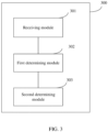
- FIG. 3 is a schematic structural diagram of an apparatus for determining a cell scheduling mode according to an embodiment of this application.
- the apparatus 300 for determining a cell scheduling mode includes a receiving module 301, a first determining module 302, and a second determining module 303.
- the receiving module 301 is configured to receive scheduling configuration information, where the scheduling configuration information indicates that a second cell of a terminal is scheduled by a first cell of the terminal and that the second cell is capable of self-scheduling; the first determining module 302 is configured to determine an activity state of the first cell; and the second determining module 303 is configured to determine a scheduling mode for the second cell based on the scheduling configuration information and the activity state.
- the scheduling configuration information further indicates at least one of the following:
- the complete UE-specific search space belongs to both the first UE-specific search space group and the second UE-specific search space group.
- the activity state of the first cell includes any one of the following:
- that the second determining module 303 determines a scheduling mode for the second cell based on the scheduling configuration information and the activity state includes:
- That the second determining module 303 determines a scheduling mode for the second cell based on the scheduling configuration information and the activity state includes:
- the some USSs are search spaces in the first UE-specific search space group, and the some USSs have a same identifier as a target search space, where the target search space is a search space in a currently active BWP of the first cell.
- the determining a scheduling mode for the second cell based on the scheduling configuration information and the activity state includes:
- the first target information includes any one of the following: deactivation signaling for the first cell, control information indicating transitioning from non-dormancy state to dormancy state, and control information indicating switching from the first BWP to the second BWP.
- the first target moment includes any one of the following:
- that the second determining module 303 determines a scheduling mode for the second cell based on the scheduling configuration information and the activity state includes:
- the target timer includes a cell deactivation timer or a BWP inactivity timer.
- the second target moment includes any one of the following:
- that the second determining module 303 determines a scheduling mode for the second cell based on the scheduling configuration information and the activity state includes:
- the third target moment includes any one of the following:
- the second target information includes any one of the following:
- the first determining module 302 is further configured to: in a case that the scheduling configuration information indicates that the second cell is scheduled by the first cell, determine a behavior undesired by the terminal through pre-negotiation, where the behavior undesired by the terminal includes at least one of the following:
- the first determining module 302 is further configured to: in a case that the scheduling configuration information indicates that the second cell is scheduled by the first cell, ignore at least one of the following:
- the first cell is a secondary cell
- the second cell is a primary cell
- the apparatus for determining a cell scheduling mode in this embodiment of this application may be an apparatus, or may be a component, an integrated circuit, or a chip of a terminal.
- the apparatus may be a mobile terminal or a non-mobile terminal.
- the mobile terminal may include but is not limited to types of the terminal 11 listed above, and the non-mobile terminal may be a server, a network attached storage (Network Attached Storage, NAS), a personal computer (personal computer, PC), a television (television, TV), a teller machine, a self-service machine, or the like. This is not specifically limited in the embodiments of this application.
- the apparatus for determining a cell scheduling mode in this embodiment of this application may be an apparatus having an operating system.
- the operating system may be an Android (Android) operating system, may be an iOS operating system, or may be another possible operating system. This is not specifically limited in the embodiments of this application.
- the apparatus for determining a cell scheduling mode provided in this embodiment of this application can implement the processes implemented in the method embodiment in FIG. 2 , with the same technical effects achieved. To avoid repetition, details are not described herein again.
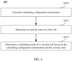
- FIG. 4 is a schematic flowchart of a method for determining a cell scheduling mode according to an embodiment of this application.
- the method 400 may be performed by a network-side device.
- the method may be performed by software or hardware installed on the network-side device.
- the method includes the following steps.
- S410 Transmit scheduling configuration information, where the scheduling configuration information indicates that a second cell of a terminal is scheduled by a first cell of the terminal and that the second cell is capable of self-scheduling.
- the method 400 is a method for a network-side device corresponding to the method 200, and has similar possible implementations to the method 200 except that the scheduling configuration information is transmitted by a network-side device in the method 400 and received by a terminal in the method 200.
- the following mainly describes some implementations of the method 400. For relevant details not described, reference may be made to the descriptions in the method 200. Details are not described herein again.
- the scheduling configuration information further indicates at least one of the following: a common search space configured on the second cell; a first UE-specific search space group configured on the second cell, where the first UE-specific search space group includes one or more complete UE-specific search spaces; a second UE-specific search space group configured on the second cell, where the second UE-specific search space group includes one or more incomplete UE-specific search spaces, or the second UE-specific search space group includes one or more UE-specific search spaces that are capable of being mapped for cross-carrier scheduling; and a search space configured on the first cell.
- the complete UE-specific search space belongs to both the first UE-specific search space group and the second UE-specific search space group.
- the activity state of the first cell includes any one of the following: the active state; the inactive state; transitioning from the active state to the inactive state; transitioning from the inactive state to the active state; the dormancy state; the non-dormancy state; transitioning from the dormancy state to the non-dormancy state; transitioning from the non-dormancy state to the dormancy state; having a search space capable of scheduling the second cell on an active BWP; having no search space capable of scheduling the second cell on an active BWP; switching from a first BWP to a second BWP, where the first BWP has a search space capable of scheduling the second cell, and the second BWP has no search space capable of scheduling the second cell; and switching from the second BWP to the first BWP.
- the determining a scheduling mode for the second cell based on the scheduling configuration information and the activity state includes: in a case that the first cell is in a first target state, determining that the second cell is cross-carrier scheduled by the search space on the first cell, and that scheduling with scrambling by a specific radio network temporary identifier RNTI is not performed in the CSS configured on the second cell and/or the first UE-specific search space group; or determining that the second cell is cross-carrier scheduled by the search space on the first cell, that scheduling with scrambling by a specific RNTI is performed in the CSS configured on the second cell, and that scheduling with scrambling by a specific RNTI is not performed in the first UE-specific search space group; where the first target state includes at least one of the following: active state; non-dormancy state; and having a search space capable of scheduling the second cell on the active BWP.
- the determining a scheduling mode for the second cell based on the scheduling configuration information and the activity state includes: in a case that the first cell is in a second target state, determining that the first cell is incapable of scheduling the second cell, and that scheduling with scrambling by a specific RNTI is performed in the CSS configured on the second cell and/or some or all USSs in the first UE-specific search space group; or determining that the first cell is incapable of scheduling the second cell, that CSS self-scheduling with scrambling by a specific RNTI is performed on the second cell, and that scheduling with scrambling by a specific RNTI is performed in the CSS configured on the second cell and some or all USSs in the first UE-specific search space group; where the second target state includes at least one of the following: the inactive state; the dormancy state; and having no search space capable of scheduling the second cell on the active BWP.
- the some USSs are search spaces in the first UE-specific search space group, and the some USSs have the same identifier as the target search space, where the target search space is a search space in a currently active BWP of the first cell.
- the determining a scheduling mode for the second cell based on the scheduling configuration information and the activity state includes: in a case that the first cell is in a third target state, at a first target moment after first target information is transmitted, enabling a function of performing scheduling with scrambling by a specific RNTI in the CSS configured on the second cell and/or the first UE-specific search space group; where the third target state includes at least one of the following: transitioning from the active state to the inactive state; transitioning from the non-dormancy state to the dormancy state; and switching from the first BWP to the second BWP.
- the first target information includes any one of the following: deactivation signaling for the first cell, control information indicating transitioning from non-dormancy state to dormancy state, and control information indicating switching from the first BWP to the second BWP.
- the first target moment includes any one of the following: an effective moment of an event indicated by the first target information; when a predetermined time has elapsed since an effective moment of an event indicated by the first target information; and a moment configured by radio resource control RRC signaling.
- the determining a scheduling mode for the second cell based on the scheduling configuration information and the activity state includes: in a case that the first cell is in a third target state, at a second target moment after a target timer expires, enabling a function of performing scheduling with scrambling by a specific RNTI in the CSS configured on the second cell and/or the first UE-specific search space group; where the third target state includes at least one of the following: transitioning from the active state to the inactive state; transitioning from the non-dormancy state to the dormancy state; and switching from the first BWP to the second BWP.
- the target timer includes a cell deactivation timer or a BWP inactivity timer.
- the second target moment includes: an effective moment of an event indicated by the expiration of the target timer; when a predetermined time has elapsed since an effective moment of an event indicated by the expiration of the target timer; or a moment configured by RRC signaling.
- the determining a scheduling mode for the second cell based on the scheduling configuration information and the activity state includes: in a case that the first cell is in a fourth target state, at a third target moment after second target information is transmitted, disabling a function of performing scheduling with scrambling by a specific RNTI in the CSS configured on the second cell and/or the first UE-specific search space group; where the fourth target state includes at least one of the following: transitioning from the inactive state to the active state; transitioning from the dormancy state to the non-dormancy state; and switching from the second BWP to the first BWP.
- the third target moment includes any one of the following: an effective moment of an event indicated by the second target information; when a predetermined time has elapsed since an effective moment of an event indicated by the second target information; and a moment configured by RRC signaling.
- the second target information includes any one of the following: activation signaling for activating the first cell; control information indicating that the first cell transitions from dormancy state to non-dormancy state; and control information indicating that the first cell switches from the second BWP to the first BWP.
- the method further includes: in a case that the scheduling configuration information indicates that the second cell is scheduled by the first cell, determining a behavior undesired by the terminal through pre-negotiation, where the behavior undesired by the terminal includes at least one of the following: transmitting control signaling for deactivating the first cell; configuring a cell deactivation timer for the first cell; and configuring a BWP inactivity timer for a BWP of the first cell capable of scheduling the second cell; and switching from a BWP of the first cell capable of scheduling the second cell to a BWP of the first cell incapable of scheduling the second cell.
- the method further includes: in a case that the scheduling configuration information indicates that the second cell is scheduled by the first cell, ignoring at least one of the following: control signaling for deactivating the first cell; configuring a cell deactivation timer for the first cell; configuring a BWP inactivity timer for a BWP of the first cell capable of scheduling the second cell; and control information indicating switching from a BWP of the first cell capable of scheduling the second cell to a BWP of the first cell incapable of scheduling the second cell.
- the first cell is a secondary cell
- the second cell is a primary cell
- FIG. 5 is a schematic structural diagram of an apparatus for determining a cell scheduling mode according to an embodiment of this application.
- the apparatus 500 includes a transmitting module 501, configured to transmit scheduling configuration information, where the scheduling configuration information indicates that a second cell of a terminal is scheduled by a first cell of the terminal and that the second cell is capable of self-scheduling; a third determining module 502, configured to determine an activity state of the first cell; and a fourth determining module 503, configured to determine a scheduling mode for the second cell based on the scheduling configuration information and the activity state.
- the scheduling configuration information further indicates at least one of the following:
- the complete UE-specific search space belongs to both the first UE-specific search space group and the second UE-specific search space group.
- the activity state of the first cell includes any one of the following:
- a fourth determining module 503 determines a scheduling mode for the second cell based on the scheduling configuration information and the activity state includes:
- That a fourth determining module 503 determines a scheduling mode for the second cell based on the scheduling configuration information and the activity state includes:
- the some USSs are search spaces in the first UE-specific search space group, and the some USSs have the same identifier as the target search space, where the target search space is a search space in a currently active BWP of the first cell.
- the determining a scheduling mode for the second cell based on the scheduling configuration information and the activity state includes:
- the first target information includes any one of the following: deactivation signaling for the first cell, control information indicating transitioning from non-dormancy state to dormancy state, and control information indicating switching from the first BWP to the second BWP.
- the first target moment includes any one of the following:
- a fourth determining module 503 determines a scheduling mode for the second cell based on the scheduling configuration information and the activity state includes:
- the target timer includes a cell deactivation timer or a BWP inactivity timer.
- the second target moment includes any one of the following:
- a fourth determining module 503 determines a scheduling mode for the second cell based on the scheduling configuration information and the activity state includes:
- the third target moment includes any one of the following:
- the second target information includes any one of the following:
- the third determining module 502 is further configured to: in a case that the scheduling configuration information indicates that the second cell is scheduled by the first cell, determine a behavior undesired by the terminal through pre-negotiation, where the behavior undesired by the terminal includes at least one of the following:
- the third determining module 502 is further configured to: in a case that the scheduling configuration information indicates that the second cell is scheduled by the first cell, ignore at least one of the following:
- the first cell is a secondary cell
- the second cell is a primary cell
- an embodiment of this application further provides a communication device 600, including a processor 601, a memory 602, and a program or instructions stored in the memory 602 and executable on the processor 601.
- a communication device 600 including a processor 601, a memory 602, and a program or instructions stored in the memory 602 and executable on the processor 601.
- the communication device 600 is a terminal, when the program or the instructions are executed by the processor 601, the processes of the foregoing embodiments of the method for determining a cell scheduling mode are implemented, with the same technical effects achieved.
- the communication device 600 is a network-side device, when the program or the instructions are executed by the processor 601, the processes of the foregoing embodiments of the method for determining a cell scheduling mode are implemented, with the same technical effects achieved. To avoid repetition, details are not described herein again.
- the terminal 700 includes but is not limited to components such as a radio frequency unit 701, a network module 702, an audio output unit 703, an input unit 704, a sensor 705, a display unit 706, a user input unit 707, an interface unit 708, a memory 709, and a processor 710.
- the terminal 700 may further include a power supply (such as a battery) for supplying power to the components.
- the power supply may be logically connected to the processor 710 through a power management system. In this way, functions such as charge management, discharge management, and power consumption management are implemented by using the power management system.
- the terminal structure shown in FIG. 5 does not constitute a limitation to the terminal.
- the terminal may include more or fewer components than shown in the figure, or a combination of some components, or components disposed differently. Details are not described herein again.
- the input unit 704 may include a graphics processing unit (Graphics Processing Unit, GPU) 7041 and a microphone 7042.
- the graphics processing unit 7041 processes image data of a static picture or a video that is obtained by an image capture apparatus (for example, a camera) in a video capture mode or an image capture mode.
- the display unit 706 may include a display panel 7061.
- the display panel 7061 may be configured in a form of a liquid crystal display, an organic light-emitting diode, or the like.
- the user input unit 707 includes a touch panel 7071 and other input devices 7072.
- the touch panel 7071 is also referred to as a touchscreen.
- the touch panel 7071 may include two parts: a touch detection apparatus and a touch controller.
- the other input devices 7072 may include but are not limited to a physical keyboard, a functional button (for example, a volume control key or a power on/off key), a trackball, a mouse, and a joystick. Details are not described here
- the radio frequency circuit 701 transmits downlink data received from a network-side device to the processor 710 for processing, and in addition, transmits uplink data to the network-side device.
- the radio frequency unit 701 includes but is not limited to an antenna, at least one amplifier, a transceiver, a coupler, a low noise amplifier, a duplexer, and the like.
- the processor 710 may include one or more processing units.
- the processor 710 may integrate an application processor and a modem processor.
- the application processor mainly processes an operating system, a user interface, an application program or instructions, and the like.
- the modem processor mainly processes wireless communication, for example, a baseband processor. It should be understood that alternatively, the modem processor may not be integrated into the processor 710.
- the radio frequency unit 701 is configured to receive scheduling configuration information, where the scheduling configuration information indicates that a second cell of the terminal is scheduled by a first cell of the terminal and that the second cell is capable of self-scheduling;
- the processor 710 determines an activity state of the first cell, and determines a scheduling mode for the second cell based on the scheduling configuration information and the activity state
- the terminal in this embodiment of the present invention further includes instructions or a program stored in the memory 709 and executable on the processor 710.
- the processor 710 invokes the instructions or program in the memory 709 to perform the method performed by the modules in FIG. 3 , with the same technical effects achieved. To avoid repetition, details are not described herein again.
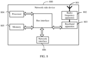
- the network-side device 800 includes an antenna 801, a radio frequency apparatus 802, and a baseband apparatus 803.
- the antenna 801 is connected to the radio frequency apparatus 802.
- the radio frequency apparatus 802 receives information by using the antenna 801, and transmits the received information to the baseband apparatus 803 for processing.
- the baseband apparatus 803 processes to-be-transmitted information, and transmits the information to the radio frequency apparatus 802; and the radio frequency apparatus 802 processes the received information and then transmits the information by using the antenna 801.
- the radio frequency apparatus may be located in the baseband apparatus 803.
- the method performed by the network-side device in the foregoing embodiment may be implemented by the baseband apparatus 803, and the baseband apparatus 803 includes a processor 804 and a memory 805.
- the baseband apparatus 803 may include, for example, at least one baseband processing unit, where a plurality of chips are disposed on the baseband processing unit. As shown in FIG. 8 , one of the chips, for example, the processor 804, is connected to the memory 805, to invoke the program in the memory 805 to perform the operations of the network device shown in the foregoing method embodiment.
- the baseband apparatus 803 may further include a network interface 806, configured to exchange information with the radio frequency apparatus 802, where the interface is, for example, a common public radio interface (common public radio interface, CPRI for short).
- a network interface 806 configured to exchange information with the radio frequency apparatus 802, where the interface is, for example, a common public radio interface (common public radio interface, CPRI for short).
- the network-side device in this embodiment of the present invention further includes instructions or a program stored in the memory 805 and executable on the processor 804.
- the processor 804 invokes the instructions or program in the memory 805 to perform the method performed by the modules in FIG. 5 , with the same technical effects achieved. To avoid repetition, details are not described herein again.
- An embodiment of this application further provides a readable storage medium, where the readable storage medium stores a program or instructions, and when the program or instructions are executed by a processor, the processes of the foregoing embodiments of the methods for determining a cell scheduling mode are implemented, with the same technical effects achieved. To avoid repetition, details are not described herein again.
- the processor is the processor of the terminal or the network-side device in the foregoing embodiments.
- the readable storage medium includes a computer-readable storage medium such as a computer read-only memory (Read-Only Memory, ROM), a random access memory (Random Access Memory, RAM), a magnetic disk, or an optical disc.
- An embodiment of this application further provides a chip.
- the chip includes a processor and a communication interface.
- the communication interface is coupled to the processor.
- the processor is configured to run a program or instructions of a network-side device to implement the processes of the foregoing embodiments of the methods for determining a cell scheduling mode, with the same technical effects achieved. To avoid repetition, details are not described herein again.
- the chip mentioned in this embodiment of this application may also be referred to as a system-level chip, a system chip, a chip system, a system-on-chip, or the like.
- the software product is stored in a storage medium (for example, ROM/RAM, a magnetic disk, or an optical disc), and includes several instructions for instructing a terminal (which may be a mobile phone, a computer, a server, an air conditioner, a network device, or the like) to perform the method described in the embodiments of this application.
- a storage medium for example, ROM/RAM, a magnetic disk, or an optical disc
- a terminal which may be a mobile phone, a computer, a server, an air conditioner, a network device, or the like
Landscapes
- Engineering & Computer Science (AREA)
- Signal Processing (AREA)
- Computer Networks & Wireless Communication (AREA)
- Mobile Radio Communication Systems (AREA)
Claims (15)
- Ein Verfahren zum Bestimmen eines Zellenplanungsmodus, das von einem Endgerät (11) durchgeführt wird und Folgendes beinhaltet:Empfangen (S210) von Planungskonfigurationsinformationen, wobei die Planungskonfigurationsinformationen anzeigen, dass eine zweite Zelle des Endgeräts (11) von einer ersten Zelle des Endgeräts (11) geplant wird und dass die zweite Zelle in der Lage ist, für sich selbst zu planen;Bestimmen (S212) eines Aktivitätszustands der ersten Zelle, wobei die erste Zelle eine sekundäre Zelle ist und die zweite Zelle eine primäre Zelle ist, und gekennzeichnet durch Folgendes:Bestimmen (S214) eines Planungsmodus für die zweite Zelle auf Grundlage der Planungskonfigurationsinformationen und des Aktivitätszustands; wobeidas Bestimmen (S214) des Planungsmodus für die zweite Zelle auf Grundlage der Planungskonfigurationsinformationen und des Aktivitätszustands Folgendes beinhaltet: in einem Fall, in dem sich die erste Zelle in einem zweiten Zielzustand befindet, Bestimmen, dass die erste Zelle nicht in der Lage ist, für die zweite Zelle zu planen, Bestimmen des Planens für sich selbst für die zweite Zelle und dass das Planen mit Verwürfelung durch eine spezifische temporäre Funknetzkennung, RNTI, in einem gemeinsamen Suchraum, CSS, der auf der zweiten Zelle konfiguriert ist, und/oder einigen oder allen UE-spezifischen Suchräumen, USS, in einer ersten UE-spezifischen Suchraumgruppe durchgeführt wird, wobeider zweite Zielzustand wenigstens eines von Folgendem beinhaltet: einen inaktiven Zustand; einen Ruhezustand; und keinen Suchraum aufweisend, der in der Lage ist, für die zweite Zelle auf einem aktiven Bandbreitenteil, BWP, zu planen.
- Verfahren gemäß Anspruch 1, wobei die Planungskonfigurationsinformationen ferner wenigstens eines von Folgendem anzeigen:einen auf der zweiten Zelle konfigurierten CSS;die erste UE-spezifische Suchraumgruppe, die auf der zweiten Zelle konfiguriert ist, wobei die erste UE-spezifische Suchraumgruppe einen oder mehrere vollständige USS beinhaltet;eine zweite UE-spezifische Suchraumgruppe, die auf der zweiten Zelle konfiguriert ist, wobei die zweite UE-spezifische Suchraumgruppe einen oder mehrere unvollständige UE-spezifische Suchräume beinhaltet, oder die zweite UE-spezifische Suchraumgruppe einen oder mehrere UE-spezifische Suchräume beinhaltet, die in der Lage sind, für trägerübergreifendes Planen abgebildet zu werden; undeinen auf der ersten Zelle konfigurierten Suchraum; wobeiin einem Fall, in dem ein vollständiger UE-spezifischer Suchraum ein Suchraum ist, der in der Lage ist, für die trägerübergreifende Planung abgebildet zu werden, der vollständige UE-spezifische Suchraum sowohl zu der ersten UE-spezifischen Suchraumgruppe als auch zu der zweiten UE-spezifischen Suchraumgruppe gehört.
- Verfahren gemäß Anspruch 1 oder 2, wobei das Verfahren ferner Folgendes beinhaltet:
in einem Fall, in dem die Planungskonfigurationsinformationen anzeigen, dass die zweite Zelle durch die erste Zelle geplant wird, Bestimmen eines von dem Endgerät (11) unerwünschten Verhaltens durch Vorverhandlung, wobei das von dem Endgerät (11) unerwünschte Verhalten wenigstens eines von Folgendem beinhaltet:Empfangen von Steuersignalen für die Deaktivierung der ersten Zelle;Konfigurieren eines Zellendeaktivierungstimers für die erste Zelle;Konfigurieren eines BWP-Inaktivitätstimers für einen BWP der ersten Zelle, der in der Lage ist, für die zweite Zelle zu planen; undUmschalten von einem BWP der ersten Zelle, der in der Lage ist, für die zweite Zelle zu planen, zu einem BWP der ersten Zelle, der nicht in der Lage ist, für die zweite Zelle zu planen. - Verfahren gemäß Anspruch 1 oder 2, wobei das Verfahren ferner Folgendes beinhaltet: in einem Fall, in dem die Planungskonfigurationsinformationen anzeigen, dass die zweite Zelle durch die erste Zelle geplant wird, Ignorieren wenigstens eines von Folgendem:Steuersignale für die Deaktivierung der ersten Zelle;Konfigurieren eines Zellendeaktivierungstimers für die erste Zelle;Konfigurieren eines BWP-Inaktivitätstimers für einen BWP der ersten Zelle, der in der Lage ist, für die zweite Zelle zu planen; undSteuerinformationen, die das Umschalten von einem BWP der ersten Zelle, der in der Lage ist, für die zweite Zelle zu planen, zu einem BWP der ersten Zelle anzeigen, der nicht in der Lage ist, für die zweite Zelle zu planen.
- Eine Einrichtung an einem Endgerät zum Bestimmen eines Zellenplanungsmodus (300), die Folgendes beinhaltet:Informationen, wobei das Empfangsmodul (301) dazu konfiguriert ist,Planungskonfigurationsinformationen zu empfangen, wobei die Planungskonfigurationsinformationen anzeigen, dass eine zweite Zelle eines Endgeräts (11) von einer ersten Zelle des Endgeräts (11) geplant wird und dass die zweite Zelle in der Lage ist, für sich selbst zu planen;ein erstes Bestimmungsmodul (302), das dazu konfiguriert ist, einen Aktivitätszustand der ersten Zelle zu bestimmen; wobei die erste Zelle eine sekundäre Zelle ist und die zweite Zelle eine primäre Zelle ist; und gekennzeichnet durch Folgendes:ein zweites Bestimmungsmodul (303), das dazu konfiguriert ist, einen Planungsmodus für die zweite Zelle auf Grundlage der Planungskonfigurationsinformationen und des Aktivitätszustands zu bestimmen; wobeidas zweite Bestimmungsmodul (30) speziell für Folgendes konfiguriert ist:in einem Fall, in dem sich die erste Zelle in einem zweiten Zielzustand befindet, Bestimmen, dass die erste Zelle nicht in der Lage ist, für die zweite Zelle zu planen,Bestimmen des Planens für sich selbst für die zweite Zelle und dass das Planen mit Verwürfelung durch eine spezifische temporäre Funknetzkennung, RNTI, in einem gemeinsamen Suchraum, CSS, der auf der zweiten Zelle konfiguriert ist, und/oder einigen oder allen UE-spezifischen Suchräumen, USS, in einer ersten UE-spezifischen Suchraumgruppe durchgeführt wird, wobeider zweite Zielzustand wenigstens eines von Folgendem beinhaltet: einen inaktiven Zustand; einen Ruhezustand; und keinen Suchraum aufweisend, der in der Lage ist, für die zweite Zelle auf einem aktiven Bandbreitenteil, BWP, zu planen.
- Einrichtung (300) gemäß Anspruch 5, wobei die Planungskonfigurationsinformationen ferner wenigstens eines von Folgendem anzeigen:einen auf der zweiten Zelle konfigurierten CSS;die erste UE-spezifische Suchraumgruppe, die auf der zweiten Zelle konfiguriert ist, wobei die erste UE-spezifische Suchraumgruppe einen oder mehrere vollständige USS beinhaltet;eine zweite UE-spezifische Suchraumgruppe, die auf der zweiten Zelle konfiguriert ist, wobei die zweite UE-spezifische Suchraumgruppe einen oder mehrere unvollständige UE-spezifische Suchräume beinhaltet, oder die zweite UE-spezifische Suchraumgruppe einen oder mehrere UE-spezifische Suchräume beinhaltet, die in der Lage sind, für trägerübergreifendes Planen abgebildet zu werden; undeinen auf der ersten Zelle konfigurierten Suchraum; wobeiin einem Fall, in dem ein vollständiger UE-spezifischer Suchraum ein Suchraum ist, der in der Lage ist, für die trägerübergreifende Planung abgebildet zu werden, der vollständige UE-spezifische Suchraum sowohl zu der ersten UE-spezifischen Suchraumgruppe als auch zu der zweiten UE-spezifischen Suchraumgruppe gehört.
- Einrichtung (300) gemäß Anspruch 5 oder 6, wobei das erste Bestimmungsmodul (302) ferner für Folgendes konfiguriert ist:
in einem Fall, in dem die Planungskonfigurationsinformationen anzeigen, dass die zweite Zelle durch die erste Zelle geplant wird, Bestimmen eines von dem Endgerät (11) unerwünschten Verhaltens durch Vorverhandlung, wobei das von dem Endgerät (11) unerwünschte Verhalten wenigstens eines von Folgendem beinhaltet:Empfangen von Steuersignalen für die Deaktivierung der ersten Zelle;Konfigurieren eines Zellendeaktivierungstimers für die erste Zelle;Konfigurieren eines BWP-Inaktivitätstimers für einen BWP der ersten Zelle, der in der Lage ist, für die zweite Zelle zu planen; undUmschalten von einem BWP der ersten Zelle, der in der Lage ist, für die zweite Zelle zu planen, zu einem BWP der ersten Zelle, der nicht in der Lage ist, für die zweite Zelle zu planen. - Einrichtung (300) gemäß Anspruch 5 oder 6, wobei das erste Bestimmungsmodul (302) ferner für Folgendes konfiguriert ist:
in einem Fall, in dem die Planungskonfigurationsinformationen anzeigen, dass die zweite Zelle durch die erste Zelle geplant wird, Ignorieren wenigstens eines von Folgendem:Steuersignale für die Deaktivierung der ersten Zelle;Konfigurieren eines Zellendeaktivierungstimers für die erste Zelle;Konfigurieren eines BWP-Inaktivitätstimers für einen BWP der ersten Zelle, der in der Lage ist, für die zweite Zelle zu planen; undSteuerinformationen, die das Umschalten von einem BWP der ersten Zelle, der in der Lage ist, für die zweite Zelle zu planen, zu einem BWP der ersten Zelle anzeigen, der nicht in der Lage ist, für die zweite Zelle zu planen. - Ein Verfahren zum Bestimmen eines Zellenplanungsmodus, das von einer netzseitigen Vorrichtung (12) durchgeführt wird, wobei das Verfahren Folgendes beinhaltet:Übertragen (S410) von Planungskonfigurationsinformationen, wobei die Planungskonfigurationsinformationen anzeigen, dass eine zweite Zelle eines Endgeräts (11) von einer ersten Zelle des Endgeräts (11) geplant wird und dass die zweite Zelle in der Lage ist, für sich selbst zu planen;Bestimmen (S412) eines Aktivitätszustands der ersten Zelle; wobei die erste Zelle eine sekundäre Zelle ist und die zweite Zelle eine primäre Zelle ist, undgekennzeichnet durch Folgendes:Bestimmen (S414) eines Planungsmodus für die zweite Zelle auf Grundlage der Planungskonfigurationsinformationen und des Aktivitätszustands; wobei das Bestimmen (S414) des Planungsmodus für die zweite Zelle auf Grundlage der Planungskonfigurationsinformationen und des Aktivitätszustand Folgendes beinhaltet: in einem Fall, in dem sich die erste Zelle in einem zweiten Zielzustand befindet, Bestimmen, dass die erste Zelle nicht in der Lage ist, für die zweite Zelle zu planen, Bestimmen des Planens für sich selbst für die zweite Zelle und dass das Planen mit Verwürfelung durch eine spezifische temporäre Funknetzkennung, RNTI, in einem gemeinsamen Suchraum, CSS, der auf der zweiten Zelle konfiguriert ist, und/oder einigen oder allen UE-spezifischen Suchräumen, USS, in einer ersten UE-spezifischen Suchraumgruppe durchgeführt wird, wobeider zweite Zielzustand wenigstens eines von Folgendem beinhaltet: einen inaktiven Zustand; einen Ruhezustand; und keinen Suchraum aufweisend, der in der Lage ist, für die zweite Zelle auf einem aktiven Bandbreitenteil, BWP, zu planen.
- Verfahren gemäß Anspruch 9, wobei die Planungskonfigurationsinformationen ferner wenigstens eines von Folgendem anzeigen:einen auf der zweiten Zelle konfigurierten CSS;die erste UE-spezifische Suchraumgruppe, die auf der zweiten Zelle konfiguriert ist, wobei die erste UE-spezifische Suchraumgruppe einen oder mehrere vollständige USS beinhaltet;eine zweite UE-spezifische Suchraumgruppe, die auf der zweiten Zelle konfiguriert ist, wobei die zweite UE-spezifische Suchraumgruppe einen oder mehrere unvollständige UE-spezifische Suchräume beinhaltet, oder die zweite UE-spezifische Suchraumgruppe einen oder mehrere UE-spezifische Suchräume beinhaltet, die in der Lage sind, für trägerübergreifendes Planen abgebildet zu werden; undeinen auf der ersten Zelle konfigurierten Suchraum; wobeiin einem Fall, in dem ein vollständiger UE-spezifischer Suchraum ein Suchraum ist, der in der Lage ist, für die trägerübergreifende Planung abgebildet zu werden, der vollständige UE-spezifische Suchraum sowohl zu der ersten UE-spezifischen Suchraumgruppe als auch zu der zweiten UE-spezifischen Suchraumgruppe gehört.
- Verfahren gemäß Anspruch 9 oder 10, wobei das Verfahren ferner Folgendes beinhaltet:
in einem Fall, in dem die Planungskonfigurationsinformationen anzeigen, dass die zweite Zelle durch die erste Zelle geplant wird, Bestimmen eines von dem Endgerät (11) unerwünschten Verhaltens durch Vorverhandlung, wobei das von dem Endgerät (11) unerwünschte Verhalten wenigstens eines von Folgendem beinhaltet:Senden von Steuersignalen für die Deaktivierung der ersten Zelle;Konfigurieren eines Zellendeaktivierungstimers für die erste Zelle;Konfigurieren eines BWP-Inaktivitätstimers für einen BWP der ersten Zelle, der in der Lage ist, für die zweite Zelle zu planen; undUmschalten von einem BWP der ersten Zelle, der in der Lage ist, für die zweite Zelle zu planen, zu einem BWP der ersten Zelle, der nicht in der Lage ist, für die zweite Zelle zu planen. - Verfahren gemäß Anspruch 9 oder 10, wobei das Verfahren ferner Folgendes beinhaltet:
in einem Fall, in dem die Planungskonfigurationsinformationen anzeigen, dass die zweite Zelle durch die erste Zelle geplant wird, Ignorieren wenigstens eines von Folgendem:Steuersignale für die Deaktivierung der ersten Zelle;Konfigurieren eines Zellendeaktivierungstimers für die erste Zelle;Konfigurieren eines BWP-Inaktivitätstimers für einen BWP der ersten Zelle, der in der Lage ist, für die zweite Zelle zu planen; undSteuerinformationen, die das Umschalten von einem BWP der ersten Zelle, der in der Lage ist, für die zweite Zelle zu planen, zu einem BWP der ersten Zelle anzeigen, der nicht in der Lage ist, für die zweite Zelle zu planen. - Eine Einrichtung an einer netzseitigen Vorrichtung zum Bestimmen eines Zellenplanungsmodus (500), die Folgendes beinhaltet:ein Übertragungsmodul (501), das dazu konfiguriert ist,Zeitplanungskonfigurationsinformationen zu übertragen, wobei die Planungskonfigurationsinformationen anzeigen, dass eine zweite Zelle eines Endgeräts (11) von einer ersten Zelle des Endgeräts (11) geplant wird und dass die zweite Zelle in der Lage ist, für sich selbst zu planen;ein drittes Bestimmungsmodul (502), das dazu konfiguriert ist, einen Aktivitätszustand der ersten Zelle zu bestimmen; wobei die erste Zelle eine sekundäre Zelle ist und die zweite Zelle eine primäre Zelle ist; und gekennzeichnet durch Folgendes:ein viertes Bestimmungsmodul (503), das dazu konfiguriert ist, einen Planungsmodus für die zweite Zelle auf Grundlage der Planungskonfigurationsinformationen und des Aktivitätszustands zu bestimmen;wobei das vierte Bestimmungsmodul (503) speziell für Folgendes konfiguriert ist:in einem Fall, in dem sich die erste Zelle in einem zweiten Zielzustand befindet, Bestimmen, dass die erste Zelle nicht in der Lage ist, für die zweite Zelle zu planen, Bestimmen des Planens für sich selbst für die zweite Zelle und dass das Planen mit Verwürfelung durch eine spezifische temporäre Funknetzkennung, RNTI, in einem gemeinsamen Suchraum, CSS, der auf der zweiten Zelle konfiguriert ist, und/oder einigen oder allen UE-spezifischen Suchräumen, USS, in einer ersten UE-spezifischen Suchraumgruppe durchgeführt wird, wobeider zweite Zielzustand wenigstens eines von Folgendem beinhaltet: einen inaktiven Zustand; einen Ruhezustand; und keinen Suchraum aufweisend, der in der Lage ist, für die zweite Zelle auf einem aktiven Bandbreitenteil, BWP, zu planen.
- Einrichtung (500) gemäß Anspruch 13, wobei die Planungskonfigurationsinformationen ferner wenigstens eines von Folgendem anzeigen:einen auf der zweiten Zelle konfigurierten CSS;die erste UE-spezifische Suchraumgruppe, die auf der zweiten Zelle konfiguriert ist, wobei die erste UE-spezifische Suchraumgruppe einen oder mehrere vollständige USS umfasst;eine zweite UE-spezifische Suchraumgruppe, die auf der zweiten Zelle konfiguriert ist, wobei die zweite UE-spezifische Suchraumgruppe einen oder mehrere unvollständige UE-spezifische Suchräume beinhaltet, oder die zweite UE-spezifische Suchraumgruppe einen oder mehrere UE-spezifische Suchräume beinhaltet, die in der Lage sind, für trägerübergreifendes Planen abgebildet zu werden; undeinen auf der ersten Zelle konfigurierten Suchraum; wobeiin einem Fall, in dem ein vollständiger UE-spezifischer Suchraum ein Suchraum ist, der in der Lage ist, für die trägerübergreifende Planung abgebildet zu werden, der vollständige UE-spezifische Suchraum sowohl zu der ersten UE-spezifischen Suchraumgruppe als auch zu der zweiten UE-spezifischen Suchraumgruppe gehört.
- Einrichtung gemäß einem der Ansprüche 5-8 oder 13-14, wobei die Einrichtung ein Chip ist.
Applications Claiming Priority (2)
| Application Number | Priority Date | Filing Date | Title |
|---|---|---|---|
| CN202010719844.7A CN113973371B (zh) | 2020-07-23 | 2020-07-23 | 小区调度方式确定方法、装置、终端及网络侧设备 |
| PCT/CN2021/107989 WO2022017479A1 (zh) | 2020-07-23 | 2021-07-22 | 小区调度方式确定方法、装置、终端及网络侧设备 |
Publications (3)
| Publication Number | Publication Date |
|---|---|
| EP4167668A1 EP4167668A1 (de) | 2023-04-19 |
| EP4167668A4 EP4167668A4 (de) | 2023-12-20 |
| EP4167668B1 true EP4167668B1 (de) | 2025-04-02 |
Family
ID=79585503
Family Applications (1)
| Application Number | Title | Priority Date | Filing Date |
|---|---|---|---|
| EP21845442.9A Active EP4167668B1 (de) | 2020-07-23 | 2021-07-22 | Verfahren zur bestimmung eines zellenplanungsschemas, vorrichtung, endgerät und netzwerkseitige vorrichtung |
Country Status (7)
| Country | Link |
|---|---|
| US (1) | US12501425B2 (de) |
| EP (1) | EP4167668B1 (de) |
| JP (1) | JP7505105B2 (de) |
| KR (1) | KR20230028444A (de) |
| CN (1) | CN113973371B (de) |
| ES (1) | ES3027160T3 (de) |
| WO (1) | WO2022017479A1 (de) |
Families Citing this family (2)
| Publication number | Priority date | Publication date | Assignee | Title |
|---|---|---|---|---|
| CN114640413B (zh) * | 2020-12-16 | 2024-01-23 | 北京紫光展锐通信技术有限公司 | 一种信道监听方法及装置 |
| CN115087123B (zh) * | 2022-06-14 | 2025-02-11 | Oppo广东移动通信有限公司 | 物理层调度装置、方法、芯片、终端、系统和存储 |
Family Cites Families (21)
| Publication number | Priority date | Publication date | Assignee | Title |
|---|---|---|---|---|
| EP2702817A1 (de) * | 2011-04-29 | 2014-03-05 | Nokia Solutions and Networks Oy | Verfahren und vorrichtung zur deaktivierung einer primär-und sekundärzelle eines benutzergeräts |
| US9185564B2 (en) * | 2012-05-11 | 2015-11-10 | Sharp Kabushiki Kaisha | Devices for sending and receiving feedback information |
| US9667399B2 (en) | 2012-11-06 | 2017-05-30 | Lg Electronics Inc. | Method of detecting control information in wireless communication system, and apparatus for same |
| US20150189574A1 (en) * | 2013-12-26 | 2015-07-02 | Samsung Electronics Co., Ltd. | Methods for dormant cell signaling for advanced cellular network |
| US9674727B2 (en) * | 2014-01-17 | 2017-06-06 | Qualcomm Incorporated | Indication of cell mode and CSI feedback rules for cell on-off procedure |
| KR102319700B1 (ko) * | 2014-05-02 | 2021-11-01 | 삼성전자 주식회사 | 무선 통신 시스템에서 선택적 채널 피드백 방법 및 장치 |
| EP3547596B1 (de) * | 2015-08-07 | 2021-09-29 | Panasonic Intellectual Property Corporation of America | Selbst- und trägerübergreifende planung |
| US10727979B2 (en) * | 2015-08-14 | 2020-07-28 | Electronics And Telecommunications Research Institute | Operation methods of communication node in network supporting licensed and unlicensed bands |
| WO2019191960A1 (en) * | 2018-04-04 | 2019-10-10 | Nec Corporation | Methods and apparatus for processing beam failure of a secondary cell |
| CN110475364B (zh) * | 2018-05-09 | 2021-03-26 | 维沃移动通信有限公司 | 一种非周期跟踪参考信号的接收方法及终端 |
| US11109397B2 (en) * | 2018-05-18 | 2021-08-31 | Comcast Cable Communications, Llc | Cross-carrier scheduling with multiple active bandwidth parts |
| US10973034B2 (en) * | 2018-11-14 | 2021-04-06 | Qualcomm Incorporated | Control resource set monitoring rules based on active quasi-co-location assumption capabilities of a user equipment (UE) |
| US11558814B2 (en) * | 2019-01-11 | 2023-01-17 | Qualcomm Incorporated | Secondary cell dormancy for new radio carrier aggregation |
| KR20200117161A (ko) * | 2019-04-03 | 2020-10-14 | 삼성전자주식회사 | 무선 통신 시스템에서 제어 정보를 모니터링하는 방법 및 장치 |
| KR20210008670A (ko) * | 2019-07-15 | 2021-01-25 | 삼성전자주식회사 | 차세대 이동 통신 시스템에서 휴면 부분 대역폭을 효율적으로 운영하는 방법 및 장치 |
| BR112022004903A2 (pt) * | 2019-09-20 | 2022-06-07 | Beijing Xiaomi Mobile Software Co Ltd | Método e dispositivo para ativar um estado de indicador de configuração de transmissão, e, meio de armazenamento de memória |
| US12439416B2 (en) * | 2019-12-25 | 2025-10-07 | Ntt Docomo, Inc. | Terminal and radio communication method |
| CN111132344B (zh) | 2019-12-27 | 2023-01-17 | 北京紫光展锐通信技术有限公司 | 跨载波调度方法、装置及存储介质 |
| CN111132359B (zh) * | 2019-12-31 | 2021-03-02 | 北京紫光展锐通信技术有限公司 | 辅小区跨载波调度主小区下行控制信息的方法及装置 |
| KR102750791B1 (ko) * | 2020-04-15 | 2025-01-09 | 아서스테크 컴퓨터 인코포레이션 | 무선 통신 시스템에서 캐리어 어그리게이션을 위한 전력 소비를 감소시키기 위한 방법 및 장치 |
| JPWO2022009288A1 (de) | 2020-07-06 | 2022-01-13 |
-
2020
- 2020-07-23 CN CN202010719844.7A patent/CN113973371B/zh active Active
-
2021
- 2021-07-22 KR KR1020237002281A patent/KR20230028444A/ko active Pending
- 2021-07-22 JP JP2023502760A patent/JP7505105B2/ja active Active
- 2021-07-22 EP EP21845442.9A patent/EP4167668B1/de active Active
- 2021-07-22 ES ES21845442T patent/ES3027160T3/es active Active
- 2021-07-22 WO PCT/CN2021/107989 patent/WO2022017479A1/zh not_active Ceased
-
2023
- 2023-01-12 US US18/153,552 patent/US12501425B2/en active Active
Also Published As
| Publication number | Publication date |
|---|---|
| JP7505105B2 (ja) | 2024-06-24 |
| EP4167668A4 (de) | 2023-12-20 |
| CN113973371A (zh) | 2022-01-25 |
| US20230156697A1 (en) | 2023-05-18 |
| WO2022017479A1 (zh) | 2022-01-27 |
| EP4167668A1 (de) | 2023-04-19 |
| US12501425B2 (en) | 2025-12-16 |
| JP2023533346A (ja) | 2023-08-02 |
| ES3027160T3 (en) | 2025-06-12 |
| CN113973371B (zh) | 2025-10-28 |
| KR20230028444A (ko) | 2023-02-28 |
Similar Documents
| Publication | Publication Date | Title |
|---|---|---|
| JP7802906B2 (ja) | 初期帯域幅部分構成の取得方法、端末及びネットワーク側機器 | |
| EP4468790A1 (de) | Verfahren und vorrichtung zur konfigurationsbestimmung, endgerät und netzwerkseitige vorrichtung | |
| US12279266B2 (en) | Information transmission method, base station and terminal | |
| US20230156597A1 (en) | Dormancy indication method and apparatus, terminal, and network-side device | |
| US20240023131A1 (en) | Pdcch monitoring method, terminal, and network side device | |
| US20230354369A1 (en) | Method for processing pdcch monitoring capability, terminal, and network-side device | |
| CN115529113A (zh) | 参考信号的传输方法和设备 | |
| US20230354164A1 (en) | Search space group switching method and apparatus | |
| US20230095844A1 (en) | Beam failure recovery method and apparatus, and device | |
| US12543167B2 (en) | Information transmission method and communication device | |
| US20220150869A1 (en) | Assignment of a second ue identity to adjust paging timing for ue for wireless network | |
| US12538325B2 (en) | Transmission mode determining method and apparatus, and communications device | |
| US20250056413A1 (en) | Signal receiving method and apparatus and terminal | |
| US12501425B2 (en) | Method for determining cell scheduling mode, terminal, and network-side device | |
| KR20230124733A (ko) | 검색 공간 그룹 전환 방법 및 장치 | |
| WO2021203324A1 (en) | SCell Dormancy Reliability Improvement | |
| EP4178259B1 (de) | Css-überwachungsverfahren und endgerät | |
| US20240357664A1 (en) | Communication operation execution method and apparatus, terminal, and storage medium | |
| US12452899B2 (en) | Signal transmission method, terminal device, and network device | |
| WO2022143808A1 (zh) | 速率匹配方法和设备 | |
| EP4383626A1 (de) | Verfahren und vorrichtung zur bestimmung von strahlinformationen sowie kommunikationsvorrichtung und speichermedium | |
| WO2025167863A1 (zh) | Prach资源确定、指示方法、装置、终端及网络侧设备 |
Legal Events
| Date | Code | Title | Description |
|---|---|---|---|
| STAA | Information on the status of an ep patent application or granted ep patent |
Free format text: STATUS: THE INTERNATIONAL PUBLICATION HAS BEEN MADE |
|
| PUAI | Public reference made under article 153(3) epc to a published international application that has entered the european phase |
Free format text: ORIGINAL CODE: 0009012 |
|
| STAA | Information on the status of an ep patent application or granted ep patent |
Free format text: STATUS: REQUEST FOR EXAMINATION WAS MADE |
|
| 17P | Request for examination filed |
Effective date: 20230113 |
|
| AK | Designated contracting states |
Kind code of ref document: A1 Designated state(s): AL AT BE BG CH CY CZ DE DK EE ES FI FR GB GR HR HU IE IS IT LI LT LU LV MC MK MT NL NO PL PT RO RS SE SI SK SM TR |
|
| DAV | Request for validation of the european patent (deleted) | ||
| DAX | Request for extension of the european patent (deleted) | ||
| REG | Reference to a national code |
Ref country code: DE Ref legal event code: R079 Free format text: PREVIOUS MAIN CLASS: H04W0072040000 Ipc: H04L0005000000 Ref country code: DE Ref legal event code: R079 Ref document number: 602021028661 Country of ref document: DE Free format text: PREVIOUS MAIN CLASS: H04W0072040000 Ipc: H04L0005000000 |
|
| A4 | Supplementary search report drawn up and despatched |
Effective date: 20231120 |
|
| RIC1 | Information provided on ipc code assigned before grant |
Ipc: H04W 72/23 20230101ALN20231114BHEP Ipc: H04W 72/1263 20230101ALN20231114BHEP Ipc: H04W 72/53 20230101ALI20231114BHEP Ipc: H04L 5/00 20060101AFI20231114BHEP |
|
| GRAP | Despatch of communication of intention to grant a patent |
Free format text: ORIGINAL CODE: EPIDOSNIGR1 |
|
| STAA | Information on the status of an ep patent application or granted ep patent |
Free format text: STATUS: GRANT OF PATENT IS INTENDED |
|
| RIC1 | Information provided on ipc code assigned before grant |
Ipc: H04W 72/23 20230101ALN20241120BHEP Ipc: H04W 72/1263 20230101ALN20241120BHEP Ipc: H04W 72/53 20230101ALI20241120BHEP Ipc: H04L 5/00 20060101AFI20241120BHEP |
|
| RIC1 | Information provided on ipc code assigned before grant |
Ipc: H04W 72/23 20230101ALN20241122BHEP Ipc: H04W 72/1263 20230101ALN20241122BHEP Ipc: H04W 72/53 20230101ALI20241122BHEP Ipc: H04L 5/00 20060101AFI20241122BHEP |
|
| INTG | Intention to grant announced |
Effective date: 20241211 |
|
| GRAS | Grant fee paid |
Free format text: ORIGINAL CODE: EPIDOSNIGR3 |
|
| GRAA | (expected) grant |
Free format text: ORIGINAL CODE: 0009210 |
|
| STAA | Information on the status of an ep patent application or granted ep patent |
Free format text: STATUS: THE PATENT HAS BEEN GRANTED |
|
| AK | Designated contracting states |
Kind code of ref document: B1 Designated state(s): AL AT BE BG CH CY CZ DE DK EE ES FI FR GB GR HR HU IE IS IT LI LT LU LV MC MK MT NL NO PL PT RO RS SE SI SK SM TR |
|
| REG | Reference to a national code |
Ref country code: GB Ref legal event code: FG4D |
|
| REG | Reference to a national code |
Ref country code: CH Ref legal event code: EP |
|
| REG | Reference to a national code |
Ref country code: IE Ref legal event code: FG4D |
|
| REG | Reference to a national code |
Ref country code: DE Ref legal event code: R096 Ref document number: 602021028661 Country of ref document: DE |
|
| REG | Reference to a national code |
Ref country code: NL Ref legal event code: FP |
|
| REG | Reference to a national code |
Ref country code: ES Ref legal event code: FG2A Ref document number: 3027160 Country of ref document: ES Kind code of ref document: T3 Effective date: 20250612 |
|
| PGFP | Annual fee paid to national office [announced via postgrant information from national office to epo] |
Ref country code: GB Payment date: 20250529 Year of fee payment: 5 |
|
| PGFP | Annual fee paid to national office [announced via postgrant information from national office to epo] |
Ref country code: NL Payment date: 20250613 Year of fee payment: 5 |
|
| PGFP | Annual fee paid to national office [announced via postgrant information from national office to epo] |
Ref country code: FR Payment date: 20250610 Year of fee payment: 5 |
|
| REG | Reference to a national code |
Ref country code: AT Ref legal event code: MK05 Ref document number: 1782366 Country of ref document: AT Kind code of ref document: T Effective date: 20250402 |
|
| PG25 | Lapsed in a contracting state [announced via postgrant information from national office to epo] |
Ref country code: FI Free format text: LAPSE BECAUSE OF FAILURE TO SUBMIT A TRANSLATION OF THE DESCRIPTION OR TO PAY THE FEE WITHIN THE PRESCRIBED TIME-LIMIT Effective date: 20250402 Ref country code: PT Free format text: LAPSE BECAUSE OF FAILURE TO SUBMIT A TRANSLATION OF THE DESCRIPTION OR TO PAY THE FEE WITHIN THE PRESCRIBED TIME-LIMIT Effective date: 20250804 |
|
| PGFP | Annual fee paid to national office [announced via postgrant information from national office to epo] |
Ref country code: ES Payment date: 20250807 Year of fee payment: 5 |
|
| PGFP | Annual fee paid to national office [announced via postgrant information from national office to epo] |
Ref country code: DE Payment date: 20250528 Year of fee payment: 5 |
|
| REG | Reference to a national code |
Ref country code: LT Ref legal event code: MG9D |
|
| PG25 | Lapsed in a contracting state [announced via postgrant information from national office to epo] |
Ref country code: NO Free format text: LAPSE BECAUSE OF FAILURE TO SUBMIT A TRANSLATION OF THE DESCRIPTION OR TO PAY THE FEE WITHIN THE PRESCRIBED TIME-LIMIT Effective date: 20250702 Ref country code: GR Free format text: LAPSE BECAUSE OF FAILURE TO SUBMIT A TRANSLATION OF THE DESCRIPTION OR TO PAY THE FEE WITHIN THE PRESCRIBED TIME-LIMIT Effective date: 20250703 |
|
| PG25 | Lapsed in a contracting state [announced via postgrant information from national office to epo] |
Ref country code: PL Free format text: LAPSE BECAUSE OF FAILURE TO SUBMIT A TRANSLATION OF THE DESCRIPTION OR TO PAY THE FEE WITHIN THE PRESCRIBED TIME-LIMIT Effective date: 20250402 |
|
| PGFP | Annual fee paid to national office [announced via postgrant information from national office to epo] |
Ref country code: IT Payment date: 20250623 Year of fee payment: 5 |
|
| PG25 | Lapsed in a contracting state [announced via postgrant information from national office to epo] |
Ref country code: BG Free format text: LAPSE BECAUSE OF FAILURE TO SUBMIT A TRANSLATION OF THE DESCRIPTION OR TO PAY THE FEE WITHIN THE PRESCRIBED TIME-LIMIT Effective date: 20250402 |
|
| PG25 | Lapsed in a contracting state [announced via postgrant information from national office to epo] |
Ref country code: HR Free format text: LAPSE BECAUSE OF FAILURE TO SUBMIT A TRANSLATION OF THE DESCRIPTION OR TO PAY THE FEE WITHIN THE PRESCRIBED TIME-LIMIT Effective date: 20250402 |
|
| PG25 | Lapsed in a contracting state [announced via postgrant information from national office to epo] |
Ref country code: AT Free format text: LAPSE BECAUSE OF FAILURE TO SUBMIT A TRANSLATION OF THE DESCRIPTION OR TO PAY THE FEE WITHIN THE PRESCRIBED TIME-LIMIT Effective date: 20250402 |
|
| PG25 | Lapsed in a contracting state [announced via postgrant information from national office to epo] |
Ref country code: RS Free format text: LAPSE BECAUSE OF FAILURE TO SUBMIT A TRANSLATION OF THE DESCRIPTION OR TO PAY THE FEE WITHIN THE PRESCRIBED TIME-LIMIT Effective date: 20250702 |
|
| PG25 | Lapsed in a contracting state [announced via postgrant information from national office to epo] |
Ref country code: IS Free format text: LAPSE BECAUSE OF FAILURE TO SUBMIT A TRANSLATION OF THE DESCRIPTION OR TO PAY THE FEE WITHIN THE PRESCRIBED TIME-LIMIT Effective date: 20250802 |
|
| PG25 | Lapsed in a contracting state [announced via postgrant information from national office to epo] |
Ref country code: LV Free format text: LAPSE BECAUSE OF FAILURE TO SUBMIT A TRANSLATION OF THE DESCRIPTION OR TO PAY THE FEE WITHIN THE PRESCRIBED TIME-LIMIT Effective date: 20250402 |
|
| PG25 | Lapsed in a contracting state [announced via postgrant information from national office to epo] |
Ref country code: SM Free format text: LAPSE BECAUSE OF FAILURE TO SUBMIT A TRANSLATION OF THE DESCRIPTION OR TO PAY THE FEE WITHIN THE PRESCRIBED TIME-LIMIT Effective date: 20250402 Ref country code: DK Free format text: LAPSE BECAUSE OF FAILURE TO SUBMIT A TRANSLATION OF THE DESCRIPTION OR TO PAY THE FEE WITHIN THE PRESCRIBED TIME-LIMIT Effective date: 20250402 |
|
| PG25 | Lapsed in a contracting state [announced via postgrant information from national office to epo] |
Ref country code: CZ Free format text: LAPSE BECAUSE OF FAILURE TO SUBMIT A TRANSLATION OF THE DESCRIPTION OR TO PAY THE FEE WITHIN THE PRESCRIBED TIME-LIMIT Effective date: 20250402 |
|
| PG25 | Lapsed in a contracting state [announced via postgrant information from national office to epo] |
Ref country code: EE Free format text: LAPSE BECAUSE OF FAILURE TO SUBMIT A TRANSLATION OF THE DESCRIPTION OR TO PAY THE FEE WITHIN THE PRESCRIBED TIME-LIMIT Effective date: 20250402 |
|
| PG25 | Lapsed in a contracting state [announced via postgrant information from national office to epo] |
Ref country code: SK Free format text: LAPSE BECAUSE OF FAILURE TO SUBMIT A TRANSLATION OF THE DESCRIPTION OR TO PAY THE FEE WITHIN THE PRESCRIBED TIME-LIMIT Effective date: 20250402 |
|
| PLBE | No opposition filed within time limit |
Free format text: ORIGINAL CODE: 0009261 |
|
| STAA | Information on the status of an ep patent application or granted ep patent |
Free format text: STATUS: NO OPPOSITION FILED WITHIN TIME LIMIT |
|
| PG25 | Lapsed in a contracting state [announced via postgrant information from national office to epo] |
Ref country code: RO Free format text: LAPSE BECAUSE OF FAILURE TO SUBMIT A TRANSLATION OF THE DESCRIPTION OR TO PAY THE FEE WITHIN THE PRESCRIBED TIME-LIMIT Effective date: 20250402 |
|
| REG | Reference to a national code |
Ref country code: CH Ref legal event code: L10 Free format text: ST27 STATUS EVENT CODE: U-0-0-L10-L00 (AS PROVIDED BY THE NATIONAL OFFICE) Effective date: 20260211 |