EP4166937A1 - Inspection apparatus and inspection method for display device - Google Patents
Inspection apparatus and inspection method for display device Download PDFInfo
- Publication number
- EP4166937A1 EP4166937A1 EP22201635.4A EP22201635A EP4166937A1 EP 4166937 A1 EP4166937 A1 EP 4166937A1 EP 22201635 A EP22201635 A EP 22201635A EP 4166937 A1 EP4166937 A1 EP 4166937A1
- Authority
- EP
- European Patent Office
- Prior art keywords
- display device
- light
- inspection
- reflected light
- inspection apparatus
- Prior art date
- Legal status (The legal status is an assumption and is not a legal conclusion. Google has not performed a legal analysis and makes no representation as to the accuracy of the status listed.)
- Granted
Links
Images






Classifications
-
- G—PHYSICS
- G01—MEASURING; TESTING
- G01N—INVESTIGATING OR ANALYSING MATERIALS BY DETERMINING THEIR CHEMICAL OR PHYSICAL PROPERTIES
- G01N21/00—Investigating or analysing materials by the use of optical means, i.e. using sub-millimetre waves, infrared, visible or ultraviolet light
- G01N21/84—Systems specially adapted for particular applications
- G01N21/88—Investigating the presence of flaws or contamination
- G01N21/8806—Specially adapted optical and illumination features
-
- G—PHYSICS
- G01—MEASURING; TESTING
- G01N—INVESTIGATING OR ANALYSING MATERIALS BY DETERMINING THEIR CHEMICAL OR PHYSICAL PROPERTIES
- G01N21/00—Investigating or analysing materials by the use of optical means, i.e. using sub-millimetre waves, infrared, visible or ultraviolet light
- G01N21/84—Systems specially adapted for particular applications
- G01N21/88—Investigating the presence of flaws or contamination
- G01N21/8851—Scan or image signal processing specially adapted therefor, e.g. for scan signal adjustment, for detecting different kinds of defects, for compensating for structures, markings, edges
-
- G—PHYSICS
- G01—MEASURING; TESTING
- G01N—INVESTIGATING OR ANALYSING MATERIALS BY DETERMINING THEIR CHEMICAL OR PHYSICAL PROPERTIES
- G01N21/00—Investigating or analysing materials by the use of optical means, i.e. using sub-millimetre waves, infrared, visible or ultraviolet light
- G01N21/84—Systems specially adapted for particular applications
- G01N21/88—Investigating the presence of flaws or contamination
- G01N21/95—Investigating the presence of flaws or contamination characterised by the material or shape of the object to be examined
- G01N21/958—Inspecting transparent materials or objects, e.g. windscreens
-
- G—PHYSICS
- G01—MEASURING; TESTING
- G01B—MEASURING LENGTH, THICKNESS OR SIMILAR LINEAR DIMENSIONS; MEASURING ANGLES; MEASURING AREAS; MEASURING IRREGULARITIES OF SURFACES OR CONTOURS
- G01B11/00—Measuring arrangements characterised by the use of optical techniques
- G01B11/24—Measuring arrangements characterised by the use of optical techniques for measuring contours or curvatures
- G01B11/25—Measuring arrangements characterised by the use of optical techniques for measuring contours or curvatures by projecting a pattern, e.g. one or more lines, moiré fringes on the object
- G01B11/2513—Measuring arrangements characterised by the use of optical techniques for measuring contours or curvatures by projecting a pattern, e.g. one or more lines, moiré fringes on the object with several lines being projected in more than one direction, e.g. grids, patterns
-
- G—PHYSICS
- G01—MEASURING; TESTING
- G01N—INVESTIGATING OR ANALYSING MATERIALS BY DETERMINING THEIR CHEMICAL OR PHYSICAL PROPERTIES
- G01N21/00—Investigating or analysing materials by the use of optical means, i.e. using sub-millimetre waves, infrared, visible or ultraviolet light
- G01N21/84—Systems specially adapted for particular applications
- G01N21/88—Investigating the presence of flaws or contamination
- G01N21/93—Detection standards; Calibrating baseline adjustment, drift correction
-
- G—PHYSICS
- G01—MEASURING; TESTING
- G01N—INVESTIGATING OR ANALYSING MATERIALS BY DETERMINING THEIR CHEMICAL OR PHYSICAL PROPERTIES
- G01N21/00—Investigating or analysing materials by the use of optical means, i.e. using sub-millimetre waves, infrared, visible or ultraviolet light
- G01N21/84—Systems specially adapted for particular applications
- G01N21/88—Investigating the presence of flaws or contamination
- G01N21/95—Investigating the presence of flaws or contamination characterised by the material or shape of the object to be examined
-
- G—PHYSICS
- G01—MEASURING; TESTING
- G01N—INVESTIGATING OR ANALYSING MATERIALS BY DETERMINING THEIR CHEMICAL OR PHYSICAL PROPERTIES
- G01N21/00—Investigating or analysing materials by the use of optical means, i.e. using sub-millimetre waves, infrared, visible or ultraviolet light
- G01N21/84—Systems specially adapted for particular applications
- G01N21/88—Investigating the presence of flaws or contamination
- G01N21/95—Investigating the presence of flaws or contamination characterised by the material or shape of the object to be examined
- G01N21/956—Inspecting patterns on the surface of objects
-
- G—PHYSICS
- G01—MEASURING; TESTING
- G01R—MEASURING ELECTRIC VARIABLES; MEASURING MAGNETIC VARIABLES
- G01R31/00—Arrangements for testing electric properties; Arrangements for locating electric faults; Arrangements for electrical testing characterised by what is being tested not provided for elsewhere
- G01R31/28—Testing of electronic circuits, e.g. by signal tracer
- G01R31/282—Testing of electronic circuits specially adapted for particular applications not provided for elsewhere
- G01R31/2825—Testing of electronic circuits specially adapted for particular applications not provided for elsewhere in household appliances or professional audio/video equipment
-
- G—PHYSICS
- G01—MEASURING; TESTING
- G01B—MEASURING LENGTH, THICKNESS OR SIMILAR LINEAR DIMENSIONS; MEASURING ANGLES; MEASURING AREAS; MEASURING IRREGULARITIES OF SURFACES OR CONTOURS
- G01B11/00—Measuring arrangements characterised by the use of optical techniques
- G01B11/24—Measuring arrangements characterised by the use of optical techniques for measuring contours or curvatures
- G01B11/25—Measuring arrangements characterised by the use of optical techniques for measuring contours or curvatures by projecting a pattern, e.g. one or more lines, moiré fringes on the object
- G01B11/2504—Calibration devices
-
- G—PHYSICS
- G01—MEASURING; TESTING
- G01N—INVESTIGATING OR ANALYSING MATERIALS BY DETERMINING THEIR CHEMICAL OR PHYSICAL PROPERTIES
- G01N21/00—Investigating or analysing materials by the use of optical means, i.e. using sub-millimetre waves, infrared, visible or ultraviolet light
- G01N21/84—Systems specially adapted for particular applications
- G01N21/88—Investigating the presence of flaws or contamination
- G01N21/8806—Specially adapted optical and illumination features
- G01N2021/8829—Shadow projection or structured background, e.g. for deflectometry
-
- G—PHYSICS
- G01—MEASURING; TESTING
- G01N—INVESTIGATING OR ANALYSING MATERIALS BY DETERMINING THEIR CHEMICAL OR PHYSICAL PROPERTIES
- G01N21/00—Investigating or analysing materials by the use of optical means, i.e. using sub-millimetre waves, infrared, visible or ultraviolet light
- G01N21/84—Systems specially adapted for particular applications
- G01N21/88—Investigating the presence of flaws or contamination
- G01N21/95—Investigating the presence of flaws or contamination characterised by the material or shape of the object to be examined
- G01N2021/9513—Liquid crystal panels
-
- G—PHYSICS
- G01—MEASURING; TESTING
- G01N—INVESTIGATING OR ANALYSING MATERIALS BY DETERMINING THEIR CHEMICAL OR PHYSICAL PROPERTIES
- G01N2201/00—Features of devices classified in G01N21/00
- G01N2201/06—Illumination; Optics
- G01N2201/066—Modifiable path; multiple paths in one sample
-
- G—PHYSICS
- G01—MEASURING; TESTING
- G01N—INVESTIGATING OR ANALYSING MATERIALS BY DETERMINING THEIR CHEMICAL OR PHYSICAL PROPERTIES
- G01N2201/00—Features of devices classified in G01N21/00
- G01N2201/12—Circuits of general importance; Signal processing
- G01N2201/127—Calibration; base line adjustment; drift compensation
- G01N2201/12746—Calibration values determination
- G01N2201/12784—Base line obtained from computation, histogram
Definitions
- the disclosure relates to an inspection apparatus and an inspection method for a display device.
- An inspection step of the display device may include inspection of whether light incident from the outside is distorted on a surface of the display device that may be visually recognized by a user.
- Multiple layers such as signal lines, transistors, and emission layers, may be formed inside the display device, a number of layers or a thickness of the layers may be different depending on a position thereof, and a layer for planarization may be formed on a region including layers having different numbers and thicknesses. Accordingly, a surface quality inspection result actually measured on a planarized layer on an outer surface of the display device may be different from a result of distortion of light that a user can actually visually recognize from the outside due to a difference in the number and thickness of inner layers.
- Embodiments have been made in an effort to provide an inspection apparatus and an inspection method for a display device, capable of increasing accuracy of quality inspection by reducing a difference between a surface quality inspection result measured on an outer surface of the display device and a distortion result of light that a user can actually visually recognize from the outside.
- An embodiment provides an inspection apparatus for a display device that may include a light supplier that supplies light to a surface of the display device, an inspection pattern portion between the display device and the light supplier, a measurement portion that measures reflected light reflected from the surface of the display device, and a processing portion that processes data of the reflected light measured by the measurement portion.
- the processing portion may include a calibration data portion including calibration data, and a calibrator calibrating the data by using the calibration data of the calibration data portion.
- a first direction that may be perpendicular to the surface of the display device and a second direction that may be perpendicular to a surface of the inspection pattern portion may form an angle with each other.
- the angle may be in a range of about 0 degrees to about 45 degrees
- the angle may be in a range of about 0 degrees to about 30 degrees.
- the inspection pattern portion may include light-blocking portions arranged to have an interval, and a light-transmitting portion positioned between two adjacent ones of the light-blocking portions.
- a distance between the two adjacent ones of the light blocking portions may be different depending on positions of the two adjacent ones.
- the inspection pattern portion may include light-transmitting portions having a uniform shape in plan view and are disposed at a regular interval.
- the measurement portion may include a camera that detects the reflected light.
- the processing portion may include an algorithmized program.
- the processing portion may detect linear distortion of the reflected light and planar distortion of the reflected light.
- the processing portion may determine the linear distortion of the reflected light by calculating a ratio of a width of the inspection pattern portion to a width of the reflected light.
- the planar distortion of the reflected light may include an orange peel and a refracting power of the reflected light.
- the processing portion may determine whether the reflected light has an abnormal defect, and may determine a ratio of the abnormal defect.
- An embodiment provides an inspection method for a display device that may include supplying light that has passed through an inspection pattern portion to a surface of the display device, measuring reflected light reflected from the surface of the display device, determining a linear distortion by using the measured reflected light, determining a planar distortion by using the measured reflected light, and calibrating the linear distortion and the planar distortion using calibration data.
- the inspection method may further include dividing the surface of the display device into measurement areas.
- the inspection pattern portion may be inclined such that a first direction that may be perpendicular to the surface of the display device and a second direction that may be perpendicular to a surface of the inspection pattern portion form an angle with each other.
- the angle may be in a range of about 0 degrees to about 45 degrees.
- the determining of the linear distortion, the determining of the planar distortion, and the calibrating may be performed with an algorithmized program.
- the determining of the linear distortion may include calculating a ratio of a width of the inspection pattern portion to a width of the reflected light.
- the determining of the planar distortion may include measuring a refracting power of the reflected light in the measurement areas, determining whether an orange peel has occurred in the measurement areas by using the refracting power, and determining whether the reflected light has an abnormal defect and determining a ratio of the abnormal defect.
- an inspection apparatus and an inspection method for a display device it may be possible to increase accuracy of quality inspection by reducing a difference between a surface quality inspection result measured on an outer surface of the display device and a distortion result of light that a user can actually visually recognize from the outside.
- the phrase “in a plan view” means when an object portion is viewed from a position (e.g., above), and the phrase “in a cross-sectional view” means when a cross-section taken by vertically cutting an object portion is viewed from a position (e.g., the side).
- connection means that two or more components are not only directly connected, but two or more components may be connected indirectly through other components, physically connected and/or electrically connected.
- FIG. 1 illustrates a schematic view of an inspection apparatus for a display device according to an embodiment.
- the inspection device 1000 may include a support 200 for supporting a target display device 100 to be inspected, and includes a light supplier 300 for supplying external light to the display device 100, an inspection pattern portion 400 positioned between the light supplier 300 and the display device 100, a measurement portion 500 for measuring reflected light reflected from the display device 100 after passing through the inspection pattern portion 400 and being incident on a surface of the display device 100, and a processor (processing portion) 600 for performing quality inspection by receiving measured data from the measurement portion 500.
- a support 200 for supporting a target display device 100 to be inspected, and includes a light supplier 300 for supplying external light to the display device 100, an inspection pattern portion 400 positioned between the light supplier 300 and the display device 100, a measurement portion 500 for measuring reflected light reflected from the display device 100 after passing through the inspection pattern portion 400 and being incident on a surface of the display device 100, and a processor (processing portion) 600 for performing quality inspection by receiving measured data from the measurement portion 500.
- the inspection pattern portion 400 may include multiple light-blocking portions arranged to have an interval and a light-transmitting portion between two adjacent light-blocking portions.
- the interval between the adjacent light-blocking portions of the inspection pattern portion 400 may not be constant, and thus light passing through the inspection pattern portion 400 may be a sinusoidal pattern in the form of a sine wave.
- the inspection pattern portion 400 may include multiple light-transmitting portions having a uniform planar shape and positioned at a regular interval.
- the light-transmitting portion may have a polygonal planar shape such as a quadrangle.
- the inspection pattern portion 400 may be inclined to form a first angle ⁇ 1 with the surface of the display device 100. More specifically, the inspection pattern portion 400 may be inclined such that a first direction DR1 perpendicular to the surface of the display device 100 and the second direction DRz perpendicular to the surface of the inspection pattern portion 400 form the first angle ⁇ 1.
- Light L emitted from the light supplier 300 may be incident on the inspection pattern portion 400 along a third direction ID parallel to the second direction DRz perpendicular to the surface of the inspection pattern portion 400.
- the light supplier 300 may supply the light L so as to be perpendicular to the surface of the inspection pattern portion 400.
- an incident angle of the light L may be adjusted as needed.
- the light supplier 300 may be positioned to be spaced apart from the inspection pattern portion 400 by an interval, and for example, a distance between the light supplier 300 and the inspection pattern portion 400 may be adjusted such that the light L emitted from the light supplier 300 can be simultaneously supplied to the inspection pattern portion 400.
- a distance between the light supplier 300 and the inspection pattern portion 400 may be adjustable.
- the light supplier 300 may include a planar light source, a linear light source, and/or a point light source, and the planar light source, the linear light source, or the point light source may include a fluorescent lamp, an LED, or the like.
- the disclosure is not limited thereto, and a shape or type of the light source of the light supplier may be changed.
- the light L supplied from the light supplier 300 to the inspection pattern portion 400 may be incident on the display device 100 to have an incident angle of the first angle ⁇ 1 after passing through the inspection pattern portion 400 in a direction parallel to the second direction DRz, the light Li incident on the display device 100 may be reflected from the surface of the display device 100 to have a reflection angle of the first angle ⁇ 1, and reflected light L2 may be measured by the measurement portion 500.
- the first angle ⁇ 1 may be about 0 degrees to about 45 degrees, and in an embodiment, maybe greater than about 0 degrees and less than about 30 degrees.
- the measurement portion 500 may include a camera capable of detecting or measuring reflected light.
- the processor 600 may include a calculator 600a for obtaining desired data by using data provided from the measurement portion 500 and a calibration data portion 600b for storing calibration data therein, and the calculator 600a may include a calibrator 600c that calibrates data by using the data of the calibration data portion 600b.
- the calculator 600a and the calibrator 600c of the processor 600 may be algorithmized programs, but the disclosure is not limited thereto.
- the quality of the display device 100 may be finally inspected by using the data calibrated by the processor 600.
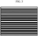
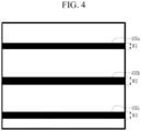
- FIG. 2 to FIG. 4 each schematically illustrate an example of the inspection pattern portion 400 of the inspection apparatus 100 for a display device according to an embodiment
- FIG. 5 to FIG. 7 each schematically illustrate an image of a defective portion that has passed through the inspection pattern portion 400 of the inspection apparatus 100 for a display device according to an embodiment.
- the light-transmitting portion is marked in white
- the light-blocking portion is marked in black.
- the inspection pattern portion 400 includes multiple light-transmitting portions, and the light-transmitting portions are arranged in a line to form a constant interval, and may have a rectangular planar shape.
- the inspection pattern portion 400 may include multiple linear light-transmitting portions extending in the same direction.
- a distance between the linear light-transmitting portions may not be constant, and may vary depending on a position thereof. Accordingly, the light passing through the inspection pattern portion 400 may be a sinusoidal pattern having the form of a sine wave.
- the inspection pattern portion 400 may include multiple linear light-transmitting portions extending in the same direction.
- a distance between the linear light-transmitting portions may be constant.
- the disclosure is not limited thereto, and the distance between the linear light-transmitting portions may be different.
- the inspection pattern portion 400 may include a first light-blocking pattern portion 400a, a second light-blocking pattern portion 400b, and a third light-blocking pattern portion 400c, and a first width W1 of the first light-blocking pattern portion 400a, a second width W2 of the second light-blocking pattern portion 400b, and a third width W 3 of the third light-blocking pattern portion 400c may be the same as or different from each other.
- a pattern change observed in a defective portion of the target display device 100 to be inspected in case that the defective portion is positioned at a portion corresponding to a center portion of the inspection pattern portion 400 will be described with reference to FIG. 5 to FIG. 7 .
- a planar shape of the portion corresponding to the defective portion may be changed.
- a rectangular planar shape of the light-transmitting portion of the inspection pattern portion 400 may be changed to a circular shape in the defective portion.
- a planar shape may change from a portion corresponding to the defective portion to a curved shape.
- FIG. 8 to FIG. 10 schematically illustrate examples of quality inspection performed by the inspection apparatus 1000 for a display device according to an embodiment.
- the inspection apparatus 1000 for a display device may measure a degree of linear distortion of a reflection pattern of light reflected from a surface of the target display device 100 to be inspected.
- a pattern width thereof may be changed.
- the linear inspection pattern 10a of the inspection pattern portion t 400 may have a first width W, but the reflection pattern 10b may have a second width W' that may be wider than the first width W.
- the first width W of the linear inspection pattern 10a may be about 0.8 mm.
- Whether the reflection pattern 10b may be deformed with respect to the linear inspection pattern 10a may be measured in a line along a portion of the surface of the display device 100.
- Whether the reflection pattern 10b may be deformed with respect to the linear inspection pattern 10a may be measured along a direction parallel to an edge of the display device 100, or may be measured along a direction forming about 45 degrees with the edge of the display device 100. Whether the reflection pattern 10b may be deformed with respect to the linear inspection pattern 10a may be measured along a position passing through a center of the display device 100.
- the inspection apparatus 1000 for a display device may measure refracting power, e.g., surface waviness, of the surface of the target display device 100 to be inspected.
- the inspection apparatus 1000 for a display device may divide a surface of the display device 100 into multiple measurement areas that may be divided in a grid shape having an interval as illustrated in FIG. 9 , and may measure whether a surface of each of the measurement areas may be deformed.
- a size of each of the measurement areas maybe greater than or equal to a resolution that can be measured by the measurement portion 500 of the inspection apparatus 1000.
- the size of the measurement area may vary depending on a size and a viewing distance of the target display device 100 to be inspected.
- the size of the measurement area may be 0.1 mm X 0.1 mm to 10 mm X 10 mm.
- Data related to the size of the measurement area may be included in the processor 600, and for example, the size of the display device 100 and viewing distance data depending on the size of the display device 100 and data of the measurement areas may be included in the processor 600.
- the refracting power of the surface of the display device 100 may be calculated by measuring a direction and a magnitude of a normal vector Nb that is perpendicular to a tangent DS contacting the surface of the measurement area.
- the refracting power may be a diopter value. Calculation of the refracting power may be performed by using the calculator 600a of the processor 600.
- a change in refracting power of each measurement area may be measured by calculating the difference between a maximum value and a minimum value of the refracting power measured in each measurement area of the surface of the display device 100 by using the calculator 600a of the processor 600, and an occurrence degree of refraction of the surface of the display device 100 may be measured by calculating an overall average value of the refracting power measured in each measurement area of the surface of the display device 100.
- a measurement area in which a magnitude of the refracting power may be large may be determined by using refracting power values measured in each measurement area of the surface of the display device 100 described above, an area with such large refracting power may be classified as a defective area, and it may be determined that orange peel has occurred in such a portion.
- An orange peel effect refers to the uneven or dimpled appearance of a lens surface.
- a defect rate of the target display device 100 to be inspected may be measured through a ratio value obtained by calculating a ratio of an area of a portion where the orange peel may be generated to a total surface area of the display device 100 by using the calculator 600a of the processor 600.
- the processor 600 of the inspection apparatus 1000 for a display device may have an abnormal area index capable of automatically determining a defect area of a portion in which an abnormal singularity occurs by measuring light reflected from the surface of the display device 100, and may determine a corresponding abnormal area index value by using data measured by the measurement portion 500. For example, in case that an abnormal area index value for reflected light for a measurement area has a certain value or more, the processor 600 may determine that a defect has occurred in the corresponding measurement area.
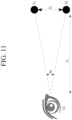
- FIG. 11 conceptually illustrates an observation interval and an observation angle depending on a distance between a user and a display device.
- the calibration data may be data collected by using data measured by the measurement portion 500 of the inspection apparatus 1000 for a display device and data actually observed by users.
- an observation distance De and an observation angle ⁇ a between two points Pi and P2 that can be observed by a user may be different depending on a first interval Do between a user eye UE and the target display device 100 to be inspected, which may be observed.
- a first interval Do between a user eye UE and the target display device 100 to be inspected, which may be observed.
- a user can use the display device 100 at a position having a large first distance Do, while as the size of the display device 100 decreases, the user can use the display device 100 at a position having a small first distance Do.
- a viewing distance of a large television may be greater than that of a laptop computer or tablet.
- the observation distance De between the two points P1 and P2 that the user can observe may increase. Conversely, as the first distance Do between the user eye UE and the display device 100, which may be observed, decreases, the observation distance De between the two points P1 and P2 that the user can observe may decrease.
- the size of the observation area of the target display device 100 to be inspected may be set differently depending on the size of the target display device 100 to be inspected.
- Data related to a difference between observed and measured values may be collected by setting the size of the observation area of the target display device 100 to be inspected depending on the size of the target display device 100 to be inspected, and comparing a value obtained by observing linear distortion and planar distortion in the observation area of the target display device 100 to be inspected by users with a degree of linear distortion of a reflection pattern of light reflected from the surface of the display device 100 and a value of a planar distortion degree using the refracting power measured in each measurement area of the surface of the display device 100 through the inspection apparatus 1000.
- the collected data may be calibration data of the calibration data portion 600b included in the processor 600 of the inspection apparatus 1000 for a display device according to an embodiment.
- the calibration data of the inspection apparatus 1000 for a display device according to an embodiment is not limited thereto, and various data using a defect observed by an actual user may be used.
- the calibrator 600c of the processor 600 of the inspection apparatus 1000 for a display device may calibrate a quality inspection result measured by the measurement portion 500 of the inspection apparatus 1000 for a display device and calculated by the calculator 600a by using calibration data stored in the calibration data portion 600b.
- Multiple layers such as signal lines, transistors, and emission layers, may be stacked inside the display device, and a number or a thickness of the layers may be different depending on positions. Accordingly, a quality inspection result measured on the outer surface of the display device and a distortion result of reflected light that the user can actually visually recognize from the outside may be different from each other.
- the inspection apparatus 1000 for a display device may calibrate a quality inspection result measured by the measurement portion 500 by using data observed by a real user, by including the processor 600 including the calibration data portion 600b and the calibrator 600c in which calibration data may be stored in addition to the measurement portion 500 for measuring the reflected light reflected from the surface of the target display device 100 to be inspected, thereby reducing a difference between a surface quality inspection result measured on the outer surface of the display device and a distortion result of light that the user can actually visually recognize from the outside and increasing accuracy of the quality inspection result.
- FIG. 12 illustrates a flowchart showing an inspection method of a display device according to an embodiment.
- an inspecting method 2000 of a display device may include installing the target display device 100 to be inspected on the support 200 of the inspection apparatus 1000 for a display device (S100).
- the inspection method of a display device may include supplying the light passing through the inspection pattern portion 400 to the display device 100 using the light supplier 300 after positioning the inspection pattern portion 400 to be inclined to form the first angle ⁇ 1 with a surface of the display device 100 (S200).
- the inspection pattern portion 400 may include light-blocking portions arranged to have an interval and a light-transmitting portion between two adjacent light-blocking portions.
- the interval between the adjacent light-transmitting portions of the inspection pattern portion 400 may not be constant, and thus light passing through the inspection pattern portion 400 may be a sinusoidal pattern in the form of a sine wave.
- the inspection pattern portion 400 may include light-transmitting portions having a uniform planar shape and positioned at a regular interval.
- the light-transmitting portion may have a polygonal planar shape such as a quadrangle.
- the inspection pattern portion 400 may be inclined to form a first angle ⁇ 1 with the surface of the display device 100. More specifically, the inspection pattern portion 400 may be inclined such that a first direction DR1 perpendicular to the surface of the display device 100 and the second direction DRz perpendicular to the surface of the inspection pattern portion 400 form the first angle ⁇ 1.
- the first angle ⁇ 1 may be about 0 degrees to about 45 degrees, and in an embodiment, may be greater than about 0 degrees and less than about 30 degrees.
- the inspection method of a display device may include measuring reflected light reflected from the surface of the display device 100 by using the measurement portion 500 (S300).
- Light incident on the surface of the display device 100 to form the first angle ⁇ 1 with respect to the first direction DR1 that may be perpendicular to the surface of the display device 100 may be reflected from the surface of the display device 100 in a direction forming the first angle ⁇ 1 with respect to the first direction DR1, and the measurement portion 500 may measure reflected light reflected from the surface of the display device 100.
- the inspection method of a display device may include dividing the target display device 100 to be inspected into multiple measurement areas (S400).
- the surface of the display device 100 may be divided into multiple measurement areas that may be divided in a grid shape having an interval.
- a size of each of the measurement areas may be greater than or equal to a resolution that can be measured by the measurement portion 500 of the inspection apparatus 1000.
- the size of the measurement area may vary depending on a size and a viewing distance of the target display device 100 to be inspected.
- a user can use the display device 100 at a position having a large first distance Do, while as the size of the display device 100 decreases, the user can use the display device 100 at a position having a small first distance Do.
- the observation distance De between the two points P1 and P2 that the user can observe may increase.
- the observation distance De between the two points P1 and P2 that the user can observe may decrease.
- the size of the measurement area of the target display device 100 to be inspected may be set differently depending on the size of the target display device 100 to be inspected.
- the size of the measurement area may be 0.1 mm X 0.1 mm to 10 mm X 10 mm.
- Data related to the size of the measurement area may be included in the processor 600, and for example, the size of the display device 100 and viewing distance data depending on the size of the display device 100 and data of the measurement areas may be included in the processor 600.
- the method of inspecting a display device may include determining whether the reflected light may be linearly distorted by using reflected light data measured by the measurement portion 500 (S500).
- Whether the reflection pattern 10b may be deformed with respect to the linear inspection pattern 10a may be measured in a line along a portion of the surface of the display device 100. For example, whether the reflection pattern 10b may be deformed with respect to the linear inspection pattern 10a may be measured along a direction parallel to an edge of the display device 100, or may be measured along a direction forming about 45 degrees with the edge of the display device 100. Whether the reflection pattern 10b may be deformed with respect to the linear inspection pattern 10a may be measured along a position passing through a center of the display device 100.
- An inspection method of a display device may include determining planar distortion of measurement areas by using data of reflected light measured by the measurement portion 500 (S600).
- Refracting power of light reflected from surfaces of the measurement areas may be calculated.
- the refracting power of the surface of the display device 100 may be calculated by measuring a direction and a magnitude of a normal vector Nb that is perpendicular to a tangent DS contacting the surface of the measurement area.
- the refracting power may be a diopter value, and the calculation of the refracting power may be performed by using the calculator 600a of the processor 600.
- a change in refracting power of each measurement area may be measured by calculating the difference between a maximum value and a minimum value of the refracting power measured in each measurement area of the surface of the display device 100 by using the calculator 600a of the processor 600, and an occurrence degree of refraction of the surface of the display device 100 may be measured by calculating an overall average value of the refracting power measured in each measurement area of the surface of the display device 100.
- An area with such large refracting power may be classified as a defective area, and it may be determined that orange peel has occurred in such a portion.
- a defect rate of the target display device 100 to be inspected may be measured through a ratio value obtained by calculating a ratio of an area of a portion where the orange peel is present to a total surface area of the display device 100 by using the calculator 600a of the processor 600.
- the method of inspecting a display device may include calibrating measured and calculated linear and planar distortion by using calibration data of the calibration data portion 600b of the processor 600 (S700).
- the calibrator 600c of the inspection apparatus 1000 for a display device may calibrate a quality inspection result measured by the measurement portion 500 of the inspection apparatus 1000 for a display device and calculated by the calculator 600a by using calibration data stored in the calibration data portion 600b.
- the calibration data stored in the calibration data portion 600b of the inspection apparatus 1000 for a display device may be data related to a difference between observed and measured values by setting the size of the observation area of the target display device 100 to be inspected depending on the size of the target display device 100 to be inspected, and comparing a value obtained by observing linear distortion and planar distortion in the observation area of the target display device 100 to be inspected by users with a degree of linear distortion of a reflection pattern of light reflected from the surface of the display device 100 and a value of a planar distortion degree using the refracting power measured in each measurement area of the surface of the display device 100 through the inspection apparatus 1000.
- the calibration data of the inspection apparatus 1000 for a display device according to an embodiment is not limited thereto, and various data using a defect observed by an actual user may be used.
- the inspection method for a display device including the determining of whether the reflected light may be linearly distorted by using the reflected light data measured by the measurement portion 500 (S500), the determining of the planar distortion of the measurement areas by using the data of the reflected light measured by the measurement portion 500 (S600), and the calibrating of the measured and calculated linear and planar distortion by using the calibration data of the calibration data portion 600b of the processor 600 (S700) according to an embodiment described above may be performed in the calculator 600a and the calibrator 600c of the processor 600, and the calculator 600a and the calibrator 600c of the processor 600 may be algorithmized programs, but the disclosure is not limited thereto.
- the inspection method for a display device may include calibrating a quality inspection result measured by the measurement portion 500 using data observed by real users by using the processor 600 including the calibration data portion 600b and the calibrator 600c in which calibration data may be stored, thereby increasing accuracy of quality inspection results by reducing a difference between a surface quality inspection result measured on the outer surface of the display device and a distortion result of light that the user can actually visually recognize from the outside.
- FIG. 13 and FIG. 14 each schematically illustrate a graph showing a result of an experimental example.
- a first case, a second case, and a third case for respectively dividing the surface of the display device 100 into measurement areas of 3 mm X 3 mm, 5 mm X 5 mm, and 10 mm X 10 mm were provided.
- a quality inspection result measured by the inspection apparatus 1000 for a display device was compared with a quality observation result observed by an actual observer to calculate a ratio between the measured quality inspection result and the observation result for a case C1 before calibration without performing the calibrating of the measured and calculated linear and planar distortion by using the inspection apparatus 1000 for a display device according to an embodiment (S700) and a case C2 after calibration of the measured and calculated linear and planar distortion (S700).
- an X-axis indicates a relative value of the surface quality defect measured by the inspection apparatus 1000 for a display device
- a Y-axis indicates a relative value of the surface quality defect observed by an actual observer.
- a dotted line illustrated in FIG. 13 and FIG. 14 indicates a line in which a value measured by the inspection apparatus 1000 for a display device coincides with a quality observation result value observed by an actual observer. Accordingly, in FIG. 13 and FIG. 14 , points showing data may be close to the dotted line, and this indicates that the deviation between the quality inspection result measured by the inspection apparatus 1000 for a display device and the quality observation result observed by an actual observer may be small.
- deviation between the quality inspection result measured by the inspection apparatus 1000 for a display device and the quality observation result observed by an actual observer may be small in the case C2 after the calibration of the measured and calculated linear and planar distortion (S700) compared with the case C1 before the calibration of the measured and calculated linear and planar distortion (S700).
- the inspection apparatus 1000 for a display device and the inspection method of the display device it may be possible to reduce the difference between the surface quality inspection result measured on the outer surface of the display device and the distortion result of light that the user can actually visually recognize from the outside by calibrating the quality inspection result measured by the inspection apparatus 1000 for a display device using calibration data based on data observed by an actual observer, thereby increasing the accuracy of the quality inspection result.
Landscapes
- General Physics & Mathematics (AREA)
- Physics & Mathematics (AREA)
- Immunology (AREA)
- Pathology (AREA)
- Analytical Chemistry (AREA)
- Biochemistry (AREA)
- General Health & Medical Sciences (AREA)
- Life Sciences & Earth Sciences (AREA)
- Health & Medical Sciences (AREA)
- Chemical & Material Sciences (AREA)
- Engineering & Computer Science (AREA)
- Computer Vision & Pattern Recognition (AREA)
- Multimedia (AREA)
- General Engineering & Computer Science (AREA)
- Signal Processing (AREA)
- Investigating Materials By The Use Of Optical Means Adapted For Particular Applications (AREA)
- Testing Of Optical Devices Or Fibers (AREA)
Abstract
Description
- This application claims priority to
Korean Patent Application No. 10-2021-0136554, filed in the Korean Intellectual Property Office on October 14, 2021 - The disclosure relates to an inspection apparatus and an inspection method for a display device.
- It may be necessary to inspect a display device after the display device is manufactured.
- An inspection step of the display device may include inspection of whether light incident from the outside is distorted on a surface of the display device that may be visually recognized by a user.
- Multiple layers, such as signal lines, transistors, and emission layers, may be formed inside the display device, a number of layers or a thickness of the layers may be different depending on a position thereof, and a layer for planarization may be formed on a region including layers having different numbers and thicknesses. Accordingly, a surface quality inspection result actually measured on a planarized layer on an outer surface of the display device may be different from a result of distortion of light that a user can actually visually recognize from the outside due to a difference in the number and thickness of inner layers.
- The above information disclosed in this Background section is only for enhancement of understanding of the background of the described technology, and therefore, it may contain information that does not form the prior art that is already known to a person of ordinary skill in the art.
- Embodiments have been made in an effort to provide an inspection apparatus and an inspection method for a display device, capable of increasing accuracy of quality inspection by reducing a difference between a surface quality inspection result measured on an outer surface of the display device and a distortion result of light that a user can actually visually recognize from the outside.
- However, problems solved by the embodiments are not limited to the above-described problem. Other aspects of the disclosure will be apparent to one of ordinary skill in the art.
- An embodiment provides an inspection apparatus for a display device that may include a light supplier that supplies light to a surface of the display device, an inspection pattern portion between the display device and the light supplier, a measurement portion that measures reflected light reflected from the surface of the display device, and a processing portion that processes data of the reflected light measured by the measurement portion. The processing portion may include a calibration data portion including calibration data, and a calibrator calibrating the data by using the calibration data of the calibration data portion.
- A first direction that may be perpendicular to the surface of the display device and a second direction that may be perpendicular to a surface of the inspection pattern portion may form an angle with each other.
- The angle may be in a range of about 0 degrees to about 45 degrees
- The angle may be in a range of about 0 degrees to about 30 degrees.
- The inspection pattern portion may include light-blocking portions arranged to have an interval, and a light-transmitting portion positioned between two adjacent ones of the light-blocking portions.
- A distance between the two adjacent ones of the light blocking portions may be different depending on positions of the two adjacent ones.
- The inspection pattern portion may include light-transmitting portions having a uniform shape in plan view and are disposed at a regular interval.
- The measurement portion may include a camera that detects the reflected light.
- The processing portion may include an algorithmized program.
- The processing portion may detect linear distortion of the reflected light and planar distortion of the reflected light.
- The processing portion may determine the linear distortion of the reflected light by calculating a ratio of a width of the inspection pattern portion to a width of the reflected light.
- The planar distortion of the reflected light may include an orange peel and a refracting power of the reflected light.
- The processing portion may determine whether the reflected light has an abnormal defect, and may determine a ratio of the abnormal defect.
- An embodiment provides an inspection method for a display device that may include supplying light that has passed through an inspection pattern portion to a surface of the display device, measuring reflected light reflected from the surface of the display device, determining a linear distortion by using the measured reflected light, determining a planar distortion by using the measured reflected light, and calibrating the linear distortion and the planar distortion using calibration data.
- The inspection method may further include dividing the surface of the display device into measurement areas.
- The inspection pattern portion may be inclined such that a first direction that may be perpendicular to the surface of the display device and a second direction that may be perpendicular to a surface of the inspection pattern portion form an angle with each other.
- The angle may be in a range of about 0 degrees to about 45 degrees.
- The determining of the linear distortion, the determining of the planar distortion, and the calibrating may be performed with an algorithmized program.
- The determining of the linear distortion may include calculating a ratio of a width of the inspection pattern portion to a width of the reflected light.
- The determining of the planar distortion may include measuring a refracting power of the reflected light in the measurement areas, determining whether an orange peel has occurred in the measurement areas by using the refracting power, and determining whether the reflected light has an abnormal defect and determining a ratio of the abnormal defect.
- In accordance with an inspection apparatus and an inspection method for a display device according to embodiments, it may be possible to increase accuracy of quality inspection by reducing a difference between a surface quality inspection result measured on an outer surface of the display device and a distortion result of light that a user can actually visually recognize from the outside.
- However, effects of the embodiments are not limited to the above-described effects. Other effects will be apparent to one of ordinary skill in the art.
-
-
FIG. 1 illustrates a schematic view of an inspection apparatus for a display device according to an embodiment. -
FIG. 2 to FIG. 4 each schematically illustrate an example of an inspection pattern portion of an inspection apparatus for a display device according to an embodiment. -
FIG. 5 to FIG. 7 each schematically illustrate an image of a defective portion that has passed through an inspection pattern portion of an inspection apparatus for a display device according to an embodiment. -
FIG. 8 to FIG. 10 schematically illustrate examples of quality inspection performed by an inspection apparatus for a display device according to an embodiment. -
FIG. 11 conceptually illustrates an observation interval and an observation angle depending on a distance between a user and a display device. -
FIG. 12 illustrates a flowchart showing an inspection method of a display device according to an embodiment. -
FIG. 13 andFIG. 14 each schematically illustrate a graph showing a result of an experimental example. - The disclosure will be described more fully hereinafter with reference to the accompanying drawings, in which embodiments are shown. As those skilled in the art would realize, the described embodiments may be modified in various different ways, all without departing from the scope of the invention as defined by the claims.
- To clearly describe the disclosure, parts that are irrelevant to the description maybe omitted, and like numerals refer to like or similar constituent elements throughout the specification.
- The accompanying drawings are provided only in order to allow embodiments disclosed in the specification to be easily understood and are not to be interpreted as limiting the disclosure.
- Further, since sizes and thicknesses of constituent members shown in the accompanying drawings may be arbitrarily given for better understanding and ease of description, the disclosure is not limited to the illustrated sizes and thicknesses. In the drawings, the thicknesses of layers, films, panels, regions, etc., may be exaggerated for clarity. In the drawings, for better understanding and ease of description, the thicknesses of some layers and areas may be exaggerated.
- As used herein, the singular forms, "a," "an," and "the" are intended to include the plural forms as well, unless the context clearly indicates otherwise.
- In the specification and the claims, the term "and/or" is intended to include any combination of the terms "and" and "or" for the purpose of its meaning and interpretation. For example, "A and/or B" may be understood to mean "A, B, or A and B." The terms "and" and "or" may be used in the conjunctive or disjunctive sense and may be understood to be equivalent to "and/or."
- It will be understood that when an element such as a layer, film, region, or substrate is referred to as being "on" another element, it can be directly on the other element or intervening elements may also be present. In contrast, when an element is referred to as being "directly on" another element, there may be no intervening elements present. Further, in the specification, the word "on" or "above" means positioned on or below the object portion, and does not necessarily mean positioned on the upper side of the object portion based on a gravitational direction.
- Unless explicitly described to the contrary, the words "comprise", "have", and "include" and variations thereof will be understood to imply the inclusion of stated elements but not the exclusion of any other elements.
- Further, in the specification, the phrase "in a plan view" means when an object portion is viewed from a position (e.g., above), and the phrase "in a cross-sectional view" means when a cross-section taken by vertically cutting an object portion is viewed from a position (e.g., the side).
- In the specification, "connected" means that two or more components are not only directly connected, but two or more components may be connected indirectly through other components, physically connected and/or electrically connected.
- "About" or "approximately" as used herein is inclusive of the stated value and means within an acceptable range of deviation for the particular value as determined by one of ordinary skill in the art, considering the measurement in question and the error associated with measurement of the particular quantity (i.e., the limitations of the measurement system). For example, "about" may mean within one or more standard deviations, or within ± 30%, 20%, 10%, 5% of the stated value.
- Unless otherwise defined, all terms (including technical and scientific terms) used herein have the same meaning as commonly understood by one of ordinary skill in the art to which the disclosure pertains. It will be further understood that terms, such as those defined in commonly used dictionaries, should be interpreted as having a meaning that is consistent with their meaning in the context of the relevant art and will not be interpreted in an idealized or overly formal sense unless expressly so defined herein.
- First, an
inspection apparatus 1000 for a display device according to an embodiment will be described with reference toFIG. 1. FIG. 1 illustrates a schematic view of an inspection apparatus for a display device according to an embodiment. - The
inspection device 1000 according to an embodiment may include asupport 200 for supporting atarget display device 100 to be inspected, and includes alight supplier 300 for supplying external light to thedisplay device 100, aninspection pattern portion 400 positioned between thelight supplier 300 and thedisplay device 100, ameasurement portion 500 for measuring reflected light reflected from thedisplay device 100 after passing through theinspection pattern portion 400 and being incident on a surface of thedisplay device 100, and a processor (processing portion) 600 for performing quality inspection by receiving measured data from themeasurement portion 500. - The
inspection pattern portion 400 may include multiple light-blocking portions arranged to have an interval and a light-transmitting portion between two adjacent light-blocking portions. The interval between the adjacent light-blocking portions of theinspection pattern portion 400 may not be constant, and thus light passing through theinspection pattern portion 400 may be a sinusoidal pattern in the form of a sine wave. - The
inspection pattern portion 400 may include multiple light-transmitting portions having a uniform planar shape and positioned at a regular interval. For example, the light-transmitting portion may have a polygonal planar shape such as a quadrangle. - The
inspection pattern portion 400 may be inclined to form a first angle θ1 with the surface of thedisplay device 100. More specifically, theinspection pattern portion 400 may be inclined such that a first direction DR1 perpendicular to the surface of thedisplay device 100 and the second direction DRz perpendicular to the surface of theinspection pattern portion 400 form the first angle θ1. - Light L emitted from the
light supplier 300 may be incident on theinspection pattern portion 400 along a third direction ID parallel to the second direction DRz perpendicular to the surface of theinspection pattern portion 400. For example, thelight supplier 300 may supply the light L so as to be perpendicular to the surface of theinspection pattern portion 400. However, the disclosure is not limited thereto, and an incident angle of the light L may be adjusted as needed. - The
light supplier 300 may be positioned to be spaced apart from theinspection pattern portion 400 by an interval, and for example, a distance between thelight supplier 300 and theinspection pattern portion 400 may be adjusted such that the light L emitted from thelight supplier 300 can be simultaneously supplied to theinspection pattern portion 400. However, the disclosure is not limited thereto, and the distance between thelight supplier 300 and theinspection pattern portion 400 may be adjustable. - The
light supplier 300 may include a planar light source, a linear light source, and/or a point light source, and the planar light source, the linear light source, or the point light source may include a fluorescent lamp, an LED, or the like. However, the disclosure is not limited thereto, and a shape or type of the light source of the light supplier may be changed. - The light L supplied from the
light supplier 300 to theinspection pattern portion 400 may be incident on thedisplay device 100 to have an incident angle of the first angle θ1 after passing through theinspection pattern portion 400 in a direction parallel to the second direction DRz, the light Li incident on thedisplay device 100 may be reflected from the surface of thedisplay device 100 to have a reflection angle of the first angle θ1, and reflected light L2 may be measured by themeasurement portion 500. - The first angle θ1 may be about 0 degrees to about 45 degrees, and in an embodiment, maybe greater than about 0 degrees and less than about 30 degrees.
- The
measurement portion 500 may include a camera capable of detecting or measuring reflected light. - The
processor 600 may include acalculator 600a for obtaining desired data by using data provided from themeasurement portion 500 and acalibration data portion 600b for storing calibration data therein, and thecalculator 600a may include acalibrator 600c that calibrates data by using the data of thecalibration data portion 600b. - The
calculator 600a and the calibrator 600c of theprocessor 600 may be algorithmized programs, but the disclosure is not limited thereto. - The quality of the
display device 100 may be finally inspected by using the data calibrated by theprocessor 600. - Now, an example of the
inspection pattern portion 400 and a defective portion of theinspection apparatus 1000 for a display device according to an embodiment will be described with reference toFIG. 2 to FIG. 4 andFIG. 5 to FIG. 7 .FIG. 2 to FIG. 4 each schematically illustrate an example of theinspection pattern portion 400 of theinspection apparatus 100 for a display device according to an embodiment, andFIG. 5 to FIG. 7 each schematically illustrate an image of a defective portion that has passed through theinspection pattern portion 400 of theinspection apparatus 100 for a display device according to an embodiment. InFIG. 2 to FIG. 4 , the light-transmitting portion is marked in white, and the light-blocking portion is marked in black. - Referring to
FIG. 2 , theinspection pattern portion 400 includes multiple light-transmitting portions, and the light-transmitting portions are arranged in a line to form a constant interval, and may have a rectangular planar shape. - Referring to
FIG. 3 , theinspection pattern portion 400 may include multiple linear light-transmitting portions extending in the same direction. A distance between the linear light-transmitting portions may not be constant, and may vary depending on a position thereof. Accordingly, the light passing through theinspection pattern portion 400 may be a sinusoidal pattern having the form of a sine wave. - Referring to
FIG. 4 , theinspection pattern portion 400 may include multiple linear light-transmitting portions extending in the same direction. A distance between the linear light-transmitting portions may be constant. However, the disclosure is not limited thereto, and the distance between the linear light-transmitting portions may be different. - For example, the
inspection pattern portion 400 may include a first light-blockingpattern portion 400a, a second light-blockingpattern portion 400b, and a third light-blockingpattern portion 400c, and a first width W1 of the first light-blockingpattern portion 400a, a second width W2 of the second light-blockingpattern portion 400b, and a third width W3 of the third light-blockingpattern portion 400c may be the same as or different from each other. - A pattern change observed in a defective portion of the
target display device 100 to be inspected in case that the defective portion is positioned at a portion corresponding to a center portion of theinspection pattern portion 400 will be described with reference toFIG. 5 to FIG. 7 . - Referring to
FIG. 5 , in the case that light passing through linear light-transmitting portions of theinspection pattern portion 400 is reflected from a defective portion of thetarget display device 100 to be inspected, a planar shape of the portion corresponding to the defective portion may be changed. For example, a rectangular planar shape of the light-transmitting portion of theinspection pattern portion 400 may be changed to a circular shape in the defective portion. - Referring to
FIG. 6 andFIG. 7 , in case that light passing through linear light-transmitting portions of theinspection pattern portion 400 is reflected from a defective portion of thetarget display device 100 to be inspected, a planar shape may change from a portion corresponding to the defective portion to a curved shape. - An example of quality inspection performed by the
inspection apparatus 1000 for a display device according to an embodiment will be described with reference toFIG. 8 to FIG. 10. FIG. 8 to FIG. 10 schematically illustrate examples of quality inspection performed by theinspection apparatus 1000 for a display device according to an embodiment. - Referring to
FIG. 8 , theinspection apparatus 1000 for a display device according to an embodiment may measure a degree of linear distortion of a reflection pattern of light reflected from a surface of thetarget display device 100 to be inspected. - More specifically, as illustrated in
FIG. 8 , in case that the light passing through alinear inspection pattern 10a of theinspection pattern portion 400 is reflected on the surface of thetarget display device 100 to be inspected so as to deform areflection pattern 10b in a shape instead of in a linear form, a pattern width thereof may be changed. For example, thelinear inspection pattern 10a of the inspectionpattern portion t 400 may have a first width W, but thereflection pattern 10b may have a second width W' that may be wider than the first width W. For example, the first width W of thelinear inspection pattern 10a may be about 0.8 mm. - It maybe determined that a defect has occurred at a corresponding position as a value, obtained by calculating a ratio (R=(W/W')X100) of the first width W of the
linear inspection pattern 10a to the second width W' of thereflection pattern 10b for each position of thedisplay device 100 by using thecalculator 600a of theprocessor 600, may be smaller. - Whether the
reflection pattern 10b may be deformed with respect to thelinear inspection pattern 10a may be measured in a line along a portion of the surface of thedisplay device 100. - Whether the
reflection pattern 10b may be deformed with respect to thelinear inspection pattern 10a may be measured along a direction parallel to an edge of thedisplay device 100, or may be measured along a direction forming about 45 degrees with the edge of thedisplay device 100. Whether thereflection pattern 10b may be deformed with respect to thelinear inspection pattern 10a may be measured along a position passing through a center of thedisplay device 100. - Referring to
FIG. 9 andFIG. 10 , theinspection apparatus 1000 for a display device according to an embodiment may measure refracting power, e.g., surface waviness, of the surface of thetarget display device 100 to be inspected. - The
inspection apparatus 1000 for a display device according to an embodiment may divide a surface of thedisplay device 100 into multiple measurement areas that may be divided in a grid shape having an interval as illustrated inFIG. 9 , and may measure whether a surface of each of the measurement areas may be deformed. - A size of each of the measurement areas maybe greater than or equal to a resolution that can be measured by the
measurement portion 500 of theinspection apparatus 1000. The size of the measurement area may vary depending on a size and a viewing distance of thetarget display device 100 to be inspected. For example, the size of the measurement area may be 0.1 mm X 0.1 mm to 10 mm X 10 mm. Data related to the size of the measurement area may be included in theprocessor 600, and for example, the size of thedisplay device 100 and viewing distance data depending on the size of thedisplay device 100 and data of the measurement areas may be included in theprocessor 600. - In case that deformation occurs on the surface of the measurement area, light reflected from the surface of the measurement area may be refracted. As such, in case that light is refracted in the measurement area, as illustrated in
FIG. 10 , the refracting power of the surface of thedisplay device 100 may be calculated by measuring a direction and a magnitude of a normal vector Nb that is perpendicular to a tangent DS contacting the surface of the measurement area. For example, the refracting power may be a diopter value. Calculation of the refracting power may be performed by using thecalculator 600a of theprocessor 600. - As such, a change in refracting power of each measurement area may be measured by calculating the difference between a maximum value and a minimum value of the refracting power measured in each measurement area of the surface of the
display device 100 by using thecalculator 600a of theprocessor 600, and an occurrence degree of refraction of the surface of thedisplay device 100 may be measured by calculating an overall average value of the refracting power measured in each measurement area of the surface of thedisplay device 100. - A measurement area in which a magnitude of the refracting power may be large may be determined by using refracting power values measured in each measurement area of the surface of the
display device 100 described above, an area with such large refracting power may be classified as a defective area, and it may be determined that orange peel has occurred in such a portion. An orange peel effect refers to the uneven or dimpled appearance of a lens surface. A defect rate of thetarget display device 100 to be inspected may be measured through a ratio value obtained by calculating a ratio of an area of a portion where the orange peel may be generated to a total surface area of thedisplay device 100 by using thecalculator 600a of theprocessor 600. - The
processor 600 of theinspection apparatus 1000 for a display device may have an abnormal area index capable of automatically determining a defect area of a portion in which an abnormal singularity occurs by measuring light reflected from the surface of thedisplay device 100, and may determine a corresponding abnormal area index value by using data measured by themeasurement portion 500. For example, in case that an abnormal area index value for reflected light for a measurement area has a certain value or more, theprocessor 600 may determine that a defect has occurred in the corresponding measurement area. - As such, it may be determined whether not only linear distortion occurring on the surface of the
display device 100 but also whether planar distortion occurs by combining a linear distortion degree of a reflection pattern of light reflected from the surface of thedisplay device 100 described with reference toFIG. 8 and the refracting power measured in each measurement area of the surface of thedisplay device 100 together. - Now, calibration data of the
calibration data portion 600b included in theprocessor 600 of theinspection apparatus 1000 for a display device according to an embodiment will be described with reference toFIG. 11. FIG. 11 conceptually illustrates an observation interval and an observation angle depending on a distance between a user and a display device. - The calibration data may be data collected by using data measured by the
measurement portion 500 of theinspection apparatus 1000 for a display device and data actually observed by users. - First, referring to
FIG. 11 , an observation distance De and an observation angle θa between two points Pi and P2 that can be observed by a user may be different depending on a first interval Do between a user eye UE and thetarget display device 100 to be inspected, which may be observed. As a size of thedisplay device 100 increases, a user can use thedisplay device 100 at a position having a large first distance Do, while as the size of thedisplay device 100 decreases, the user can use thedisplay device 100 at a position having a small first distance Do. For example, a viewing distance of a large television may be greater than that of a laptop computer or tablet. - As the first distance Do between the user eye UE and the
display device 100, which may be observed, increases, the observation distance De between the two points P1 and P2 that the user can observe may increase. Conversely, as the first distance Do between the user eye UE and thedisplay device 100, which may be observed, decreases, the observation distance De between the two points P1 and P2 that the user can observe may decrease. - Accordingly, the size of the observation area of the
target display device 100 to be inspected may be set differently depending on the size of thetarget display device 100 to be inspected. - Data related to a difference between observed and measured values may be collected by setting the size of the observation area of the
target display device 100 to be inspected depending on the size of thetarget display device 100 to be inspected, and comparing a value obtained by observing linear distortion and planar distortion in the observation area of thetarget display device 100 to be inspected by users with a degree of linear distortion of a reflection pattern of light reflected from the surface of thedisplay device 100 and a value of a planar distortion degree using the refracting power measured in each measurement area of the surface of thedisplay device 100 through theinspection apparatus 1000. - As such, the collected data may be calibration data of the
calibration data portion 600b included in theprocessor 600 of theinspection apparatus 1000 for a display device according to an embodiment. However, the calibration data of theinspection apparatus 1000 for a display device according to an embodiment is not limited thereto, and various data using a defect observed by an actual user may be used. - As described above, the
calibrator 600c of theprocessor 600 of theinspection apparatus 1000 for a display device according to an embodiment may calibrate a quality inspection result measured by themeasurement portion 500 of theinspection apparatus 1000 for a display device and calculated by thecalculator 600a by using calibration data stored in thecalibration data portion 600b. - Multiple layers, such as signal lines, transistors, and emission layers, may be stacked inside the display device, and a number or a thickness of the layers may be different depending on positions. Accordingly, a quality inspection result measured on the outer surface of the display device and a distortion result of reflected light that the user can actually visually recognize from the outside may be different from each other.
- However, the
inspection apparatus 1000 for a display device according to an embodiment may calibrate a quality inspection result measured by themeasurement portion 500 by using data observed by a real user, by including theprocessor 600 including thecalibration data portion 600b and thecalibrator 600c in which calibration data may be stored in addition to themeasurement portion 500 for measuring the reflected light reflected from the surface of thetarget display device 100 to be inspected, thereby reducing a difference between a surface quality inspection result measured on the outer surface of the display device and a distortion result of light that the user can actually visually recognize from the outside and increasing accuracy of the quality inspection result. - An
inspection method 2000 for a display device using theinspection apparatus 1000 for a display device according to an embodiment will be described with reference toFIG. 12 together withFIG. 1 to FIG. 11 described above.FIG. 12 illustrates a flowchart showing an inspection method of a display device according to an embodiment. - Referring to
FIG. 12 , an inspectingmethod 2000 of a display device according to an embodiment may include installing thetarget display device 100 to be inspected on thesupport 200 of theinspection apparatus 1000 for a display device (S100). - The inspection method of a display device according to an embodiment may include supplying the light passing through the
inspection pattern portion 400 to thedisplay device 100 using thelight supplier 300 after positioning theinspection pattern portion 400 to be inclined to form the first angle θ1 with a surface of the display device 100 (S200). - The
inspection pattern portion 400 may include light-blocking portions arranged to have an interval and a light-transmitting portion between two adjacent light-blocking portions. The interval between the adjacent light-transmitting portions of theinspection pattern portion 400 may not be constant, and thus light passing through theinspection pattern portion 400 may be a sinusoidal pattern in the form of a sine wave. Unlikely, theinspection pattern portion 400 may include light-transmitting portions having a uniform planar shape and positioned at a regular interval. For example, the light-transmitting portion may have a polygonal planar shape such as a quadrangle. - The
inspection pattern portion 400 may be inclined to form a first angle θ1 with the surface of thedisplay device 100. More specifically, theinspection pattern portion 400 may be inclined such that a first direction DR1 perpendicular to the surface of thedisplay device 100 and the second direction DRz perpendicular to the surface of theinspection pattern portion 400 form the first angle θ1. - The first angle θ1 may be about 0 degrees to about 45 degrees, and in an embodiment, may be greater than about 0 degrees and less than about 30 degrees.
- The inspection method of a display device according to an embodiment may include measuring reflected light reflected from the surface of the
display device 100 by using the measurement portion 500 (S300). - Light incident on the surface of the
display device 100 to form the first angle θ1 with respect to the first direction DR1 that may be perpendicular to the surface of thedisplay device 100 may be reflected from the surface of thedisplay device 100 in a direction forming the first angle θ1 with respect to the first direction DR1, and themeasurement portion 500 may measure reflected light reflected from the surface of thedisplay device 100. - The inspection method of a display device according to an embodiment may include dividing the
target display device 100 to be inspected into multiple measurement areas (S400). - As illustrated in
FIG. 9 , the surface of thedisplay device 100 may be divided into multiple measurement areas that may be divided in a grid shape having an interval. A size of each of the measurement areas may be greater than or equal to a resolution that can be measured by themeasurement portion 500 of theinspection apparatus 1000. The size of the measurement area may vary depending on a size and a viewing distance of thetarget display device 100 to be inspected. - As described with reference to
FIG. 11 , as a size of thedisplay device 100 increases, a user can use thedisplay device 100 at a position having a large first distance Do, while as the size of thedisplay device 100 decreases, the user can use thedisplay device 100 at a position having a small first distance Do. As the first distance Do between the user eye UE and thedisplay device 100, which may be observed, increases, the observation distance De between the two points P1 and P2 that the user can observe may increase. Conversely, as the first distance Do between the user eye UE and thedisplay device 100, which may be observed, decreases, the observation distance De between the two points P1 and P2 that the user can observe may decrease. - Accordingly, the size of the measurement area of the
target display device 100 to be inspected may be set differently depending on the size of thetarget display device 100 to be inspected. - For example, the size of the measurement area may be 0.1 mm X 0.1 mm to 10 mm X 10 mm. Data related to the size of the measurement area may be included in the
processor 600, and for example, the size of thedisplay device 100 and viewing distance data depending on the size of thedisplay device 100 and data of the measurement areas may be included in theprocessor 600. - The method of inspecting a display device according to an embodiment may include determining whether the reflected light may be linearly distorted by using reflected light data measured by the measurement portion 500 (S500).
- As described with reference to
FIG. 8 , thecalculator 600a of theprocessor 600 may determine that a defect has occurred at a corresponding position by calculating a ratio (R=(W/W)X100) of the first width W of thelinear inspection pattern 10a to the second width W' of thereflection pattern 10b for each position of thedisplay device 100 by using the first width W of thelinear inspection pattern 10a of theinspection pattern portion 400 and the second width W of thereflection pattern 10b measured by themeasurement portion 500. - Whether the
reflection pattern 10b may be deformed with respect to thelinear inspection pattern 10a may be measured in a line along a portion of the surface of thedisplay device 100. For example, whether thereflection pattern 10b may be deformed with respect to thelinear inspection pattern 10a may be measured along a direction parallel to an edge of thedisplay device 100, or may be measured along a direction forming about 45 degrees with the edge of thedisplay device 100. Whether thereflection pattern 10b may be deformed with respect to thelinear inspection pattern 10a may be measured along a position passing through a center of thedisplay device 100. - An inspection method of a display device according to an embodiment may include determining planar distortion of measurement areas by using data of reflected light measured by the measurement portion 500 (S600).
- Refracting power of light reflected from surfaces of the measurement areas may be calculated. For example, as illustrated in
FIG. 10 , the refracting power of the surface of thedisplay device 100 may be calculated by measuring a direction and a magnitude of a normal vector Nb that is perpendicular to a tangent DS contacting the surface of the measurement area. The refracting power may be a diopter value, and the calculation of the refracting power may be performed by using thecalculator 600a of theprocessor 600. - As such, a change in refracting power of each measurement area may be measured by calculating the difference between a maximum value and a minimum value of the refracting power measured in each measurement area of the surface of the
display device 100 by using thecalculator 600a of theprocessor 600, and an occurrence degree of refraction of the surface of thedisplay device 100 may be measured by calculating an overall average value of the refracting power measured in each measurement area of the surface of thedisplay device 100. - An area with such large refracting power may be classified as a defective area, and it may be determined that orange peel has occurred in such a portion. A defect rate of the
target display device 100 to be inspected may be measured through a ratio value obtained by calculating a ratio of an area of a portion where the orange peel is present to a total surface area of thedisplay device 100 by using thecalculator 600a of theprocessor 600. - It may be possible to determine whether an abnormality or defect has occurred in a corresponding measurement area by using data measured by the
measurement portion 500, thereby determining a ratio of the measurement area in which the defect occurs. For example, in case that the ratio of the measurement area in which the abnormality of the reflected light has a value that may be greater than a predetermined value, it may be determined that a visible quality defect has occurred on the surface of thecorresponding display device 100. - The method of inspecting a display device according to an embodiment may include calibrating measured and calculated linear and planar distortion by using calibration data of the
calibration data portion 600b of the processor 600 (S700). - The calibrator 600c of the
inspection apparatus 1000 for a display device according to an embodiment may calibrate a quality inspection result measured by themeasurement portion 500 of theinspection apparatus 1000 for a display device and calculated by thecalculator 600a by using calibration data stored in thecalibration data portion 600b. - The calibration data stored in the
calibration data portion 600b of theinspection apparatus 1000 for a display device according to an embodiment may be data related to a difference between observed and measured values by setting the size of the observation area of thetarget display device 100 to be inspected depending on the size of thetarget display device 100 to be inspected, and comparing a value obtained by observing linear distortion and planar distortion in the observation area of thetarget display device 100 to be inspected by users with a degree of linear distortion of a reflection pattern of light reflected from the surface of thedisplay device 100 and a value of a planar distortion degree using the refracting power measured in each measurement area of the surface of thedisplay device 100 through theinspection apparatus 1000. However, the calibration data of theinspection apparatus 1000 for a display device according to an embodiment is not limited thereto, and various data using a defect observed by an actual user may be used. - The inspection method for a display device, including the determining of whether the reflected light may be linearly distorted by using the reflected light data measured by the measurement portion 500 (S500), the determining of the planar distortion of the measurement areas by using the data of the reflected light measured by the measurement portion 500 (S600), and the calibrating of the measured and calculated linear and planar distortion by using the calibration data of the
calibration data portion 600b of the processor 600 (S700) according to an embodiment described above may be performed in thecalculator 600a and the calibrator 600c of theprocessor 600, and thecalculator 600a and the calibrator 600c of theprocessor 600 may be algorithmized programs, but the disclosure is not limited thereto. - The inspection method for a display device according to an embodiment may include calibrating a quality inspection result measured by the
measurement portion 500 using data observed by real users by using theprocessor 600 including thecalibration data portion 600b and thecalibrator 600c in which calibration data may be stored, thereby increasing accuracy of quality inspection results by reducing a difference between a surface quality inspection result measured on the outer surface of the display device and a distortion result of light that the user can actually visually recognize from the outside. - Now, a result of one experimental example will be described with reference to Table 1 together with
FIG. 13 andFIG. 14 .FIG. 13 andFIG. 14 each schematically illustrate a graph showing a result of an experimental example. - In this experimental example, a first case, a second case, and a third case for respectively dividing the surface of the
display device 100 into measurement areas of 3 mm X 3 mm, 5 mm X 5 mm, and 10 mm X 10 mm were provided. A quality inspection result measured by theinspection apparatus 1000 for a display device was compared with a quality observation result observed by an actual observer to calculate a ratio between the measured quality inspection result and the observation result for a case C1 before calibration without performing the calibrating of the measured and calculated linear and planar distortion by using theinspection apparatus 1000 for a display device according to an embodiment (S700) and a case C2 after calibration of the measured and calculated linear and planar distortion (S700). - The results are shown in Table 1 below, and the results of the second case are graphically shown in
FIG. 13 andFIG.14 . - In Table 1, as a numerical value is closer to 1, this indicates that a deviation between the quality inspection result measured by the
inspection apparatus 1000 for a display device and the quality observation result observed by an actual observer may be small, and they coincide with each other.(Table 1) First case Second case Third case c1 before calibration 0.9042 0.9035 0.8775 c2 after calibration 0.9368 0.9448 0.9197 - Referring to Table 1, it can be seen that deviation between the quality inspection result measured by the
inspection apparatus 1000 for a display device and the quality observation result observed by an actual observer may be small, and they coincide with each other in the case C2 after the calibration of the measured and calculated linear and planar distortion (S700) compared with the case C1 before the calibration of the measured and calculated linear and planar distortion (S700), for the first case, the second case, and the third case for respectively dividing the surface of thedisplay device 100 into measurement areas of 3 mm X 3 mm, 5 mm X 5 mm, and 10 mm X 10 mm.FIG. 13 shows a result of the case c1 before the calibration, andFIG. 14 shows a result of the case c2 after the calibration. InFIG. 13 andFIG. 14 , an X-axis indicates a relative value of the surface quality defect measured by theinspection apparatus 1000 for a display device, and a Y-axis indicates a relative value of the surface quality defect observed by an actual observer. A dotted line illustrated inFIG. 13 andFIG. 14 indicates a line in which a value measured by theinspection apparatus 1000 for a display device coincides with a quality observation result value observed by an actual observer. Accordingly, inFIG. 13 andFIG. 14 , points showing data may be close to the dotted line, and this indicates that the deviation between the quality inspection result measured by theinspection apparatus 1000 for a display device and the quality observation result observed by an actual observer may be small. - By referring to
FIG. 13 andFIG. 14 , it can be seen that deviation between the quality inspection result measured by theinspection apparatus 1000 for a display device and the quality observation result observed by an actual observer may be small in the case C2 after the calibration of the measured and calculated linear and planar distortion (S700) compared with the case C1 before the calibration of the measured and calculated linear and planar distortion (S700). - As described above, in accordance with the
inspection apparatus 1000 for a display device and the inspection method of the display device according to an embodiment, it may be possible to reduce the difference between the surface quality inspection result measured on the outer surface of the display device and the distortion result of light that the user can actually visually recognize from the outside by calibrating the quality inspection result measured by theinspection apparatus 1000 for a display device using calibration data based on data observed by an actual observer, thereby increasing the accuracy of the quality inspection result. - While this disclosure has been described in connection with what is considered to be practical embodiments, it is to be understood that the invention is not limited to the disclosed embodiments, but, on the contrary, is intended to cover various modifications and equivalent arrangements which fall within the scope of the claims.
Claims (15)
- An inspection apparatus for a display device, comprising:a light supplier (300) configured to supply light to a surface of the display device;an inspection pattern portion (400) between the display device and the light supplier;a measurement portion (500) configured to measure reflected light reflected from the surface of the display device; anda processing portion (600) configured to process data of the reflected light measured by the measurement portion,wherein the processing portion includes:a calibration data portion (600b) configured to store calibration data; anda calibrator (600c) configured to calibrate the data of the reflected light using the calibration data.
- The inspection apparatus of claim 1, wherein a first direction that is perpendicular to the surface of the display device and a second direction that is perpendicular to a surface of the inspection pattern portion form an angle with each other, optionally wherein the angle is in the range of about 0 degrees to about 45 degrees, optionally wherein the angle is greater than 0 degrees and less than 30 degrees.
- The inspection apparatus of claim 1 or 2, wherein the inspection pattern portion includes:light-blocking portions arranged to have an interval; anda light-transmitting portion positioned between two adjacent ones of the light-blocking portions.
- The inspection apparatus of claim 3, wherein a distance between the two adjacent ones of the light blocking portions is different depending on positions of the two adjacent ones.
- The inspection apparatus of any one of the preceding claims, wherein the inspection pattern portion includes light-transmitting portions having a uniform shape in a plan view and disposed at a regular interval.
- The inspection apparatus of any one of the preceding claims, wherein the measurement portion includes a camera that is configured to detect the reflected light.
- The inspection apparatus of any one of the preceding claims, wherein the processing portion is configured to detect linear distortion of the reflected light and planar distortion of the reflected light.
- The inspection apparatus of claim 7, wherein the processing portion is configured to determine the linear distortion of the reflected light by calculating a ratio of a width of the inspection pattern portion to a width of the reflected light.
- The inspection apparatus of claim 7 or 8, wherein the planar distortion of the reflected light includes differences in values of refracting power between measurement areas of the surface of the display device.
- The inspection apparatus of claim 7, 8 or 9, wherein the processing portion is configured to determine whether the reflected light indicates a defect in a portion of the surface of the measurement device, and determine a ratio of the defective area to a total surface area of the display device.
- An inspection method for a display device, comprising:supplying light that has passed through an inspection pattern portion to a surface of the display device;measuring reflected light reflected from the surface of the display device;determining a linear distortion by using the measured reflected light;determining a planar distortion by using the measured reflected light; andcalibrating the linear distortion and the planar distortion by using calibration data.
- The inspection method of claim 11, further comprising:
dividing the surface of the display device into measurement areas. - The inspection method of claim 12, wherein the inspection pattern portion is inclined such that a first direction that is perpendicular to the surface of the display device and a second direction that is perpendicular to a surface of the inspection pattern portion form an angle with each other, optionally wherein the angle is in the range of about 0 degrees to about 45 degrees.
- The inspection method of claim 13, wherein the determining of the linear distortion includes calculating a ratio of a width of the inspection pattern portion to a width of the reflected light.
- The inspection method of claim 13 or 14, wherein the determining of the planar distortion includes:measuring a refracting power of the reflected light in the measurement areas;determining whether an orange peel has occurred in the measurement areas by using the refracting power; anddetermining whether the reflected light indicates a defect in a portion of the surface of the measurement device, and determining a ratio of the defective area to a total surface area of the display device.
Applications Claiming Priority (1)
| Application Number | Priority Date | Filing Date | Title |
|---|---|---|---|
| KR1020210136554A KR20230053767A (en) | 2021-10-14 | 2021-10-14 | Inspection apparatus and inspection method for display device |
Publications (2)
| Publication Number | Publication Date |
|---|---|
| EP4166937A1 true EP4166937A1 (en) | 2023-04-19 |
| EP4166937B1 EP4166937B1 (en) | 2025-12-03 |
Family
ID=83692840
Family Applications (1)
| Application Number | Title | Priority Date | Filing Date |
|---|---|---|---|
| EP22201635.4A Active EP4166937B1 (en) | 2021-10-14 | 2022-10-14 | Inspection apparatus and inspection method for display device |
Country Status (4)
| Country | Link |
|---|---|
| US (1) | US12247930B2 (en) |
| EP (1) | EP4166937B1 (en) |
| KR (1) | KR20230053767A (en) |
| CN (1) | CN115980082A (en) |
Families Citing this family (1)
| Publication number | Priority date | Publication date | Assignee | Title |
|---|---|---|---|---|
| WO2022227049A1 (en) * | 2021-04-30 | 2022-11-03 | 京东方科技集团股份有限公司 | Product defect information processing method and apparatus, and product defect information query method and apparatus |
Citations (5)
| Publication number | Priority date | Publication date | Assignee | Title |
|---|---|---|---|---|
| JPH11153420A (en) * | 1997-11-20 | 1999-06-08 | Sumitomo Metal Mining Co Ltd | Method and apparatus for measuring distortion of mirror-coated panel |
| US20090141287A1 (en) * | 2005-09-15 | 2009-06-04 | Jfe Steel Corporation | Surface-distortion Measuring Device and Method |
| US20170003232A1 (en) * | 2015-06-26 | 2017-01-05 | Glasstech, Inc. | System and method for measuring reflected optical distortion in contoured glass sheets |
| KR20190027295A (en) * | 2017-09-06 | 2019-03-14 | 주식회사 필옵틱스 | Detection System for Deformation of Flexible Substrate |
| CN112082512A (en) * | 2020-09-08 | 2020-12-15 | 深圳广成创新技术有限公司 | Calibration optimization method and device for phase measurement deflection technique and computer equipment |
Family Cites Families (7)
| Publication number | Priority date | Publication date | Assignee | Title |
|---|---|---|---|---|
| JP4304935B2 (en) | 2002-03-11 | 2009-07-29 | 三菱マテリアル株式会社 | Cutting tools and throwaway inserts |
| US7417722B2 (en) * | 2004-12-19 | 2008-08-26 | Kla-Tencor Technologies Corporation | System and method for controlling light scattered from a workpiece surface in a surface inspection system |
| TWI253287B (en) * | 2004-12-22 | 2006-04-11 | Benq Corp | Image capture apparatus and calibrator |
| US10289930B2 (en) * | 2017-02-09 | 2019-05-14 | Glasstech, Inc. | System and associated for online measurement of the optical characteristics of a glass sheet |
| US11694916B2 (en) | 2018-10-15 | 2023-07-04 | Koh Young Technology Inc. | Apparatus, method and recording medium storing command for inspection |
| US20210299879A1 (en) * | 2018-10-27 | 2021-09-30 | Gilbert Pinter | Machine vision systems, illumination sources for use in machine vision systems, and components for use in the illumination sources |
| KR102668970B1 (en) | 2018-12-14 | 2024-05-24 | 삼성디스플레이 주식회사 | Vision inspection apparatus and method of driving the same |
-
2021
- 2021-10-14 KR KR1020210136554A patent/KR20230053767A/en active Pending
-
2022
- 2022-08-16 US US17/888,694 patent/US12247930B2/en active Active
- 2022-10-14 EP EP22201635.4A patent/EP4166937B1/en active Active
- 2022-10-14 CN CN202211256914.5A patent/CN115980082A/en active Pending
Patent Citations (5)
| Publication number | Priority date | Publication date | Assignee | Title |
|---|---|---|---|---|
| JPH11153420A (en) * | 1997-11-20 | 1999-06-08 | Sumitomo Metal Mining Co Ltd | Method and apparatus for measuring distortion of mirror-coated panel |
| US20090141287A1 (en) * | 2005-09-15 | 2009-06-04 | Jfe Steel Corporation | Surface-distortion Measuring Device and Method |
| US20170003232A1 (en) * | 2015-06-26 | 2017-01-05 | Glasstech, Inc. | System and method for measuring reflected optical distortion in contoured glass sheets |
| KR20190027295A (en) * | 2017-09-06 | 2019-03-14 | 주식회사 필옵틱스 | Detection System for Deformation of Flexible Substrate |
| CN112082512A (en) * | 2020-09-08 | 2020-12-15 | 深圳广成创新技术有限公司 | Calibration optimization method and device for phase measurement deflection technique and computer equipment |
Also Published As
| Publication number | Publication date |
|---|---|
| CN115980082A (en) | 2023-04-18 |
| US20230123595A1 (en) | 2023-04-20 |
| KR20230053767A (en) | 2023-04-24 |
| US12247930B2 (en) | 2025-03-11 |
| EP4166937B1 (en) | 2025-12-03 |
Similar Documents
| Publication | Publication Date | Title |
|---|---|---|
| US10867381B2 (en) | Defect detection apparatus and method | |
| TWI497061B (en) | Method and apparatus for detecting defects in glass sheet | |
| US9599534B2 (en) | Optical evaluation of lenses and lens molds | |
| US11003072B2 (en) | Mask substrate inspection system | |
| TWI818186B (en) | Method and imaging system for surface inspection and evaluation | |
| EP4166937B1 (en) | Inspection apparatus and inspection method for display device | |
| CN105103027B (en) | Measurement of focus and other features in optical systems | |
| WO2016107051A1 (en) | Detection plate, detection component and detection method for detecting ripples of touch screen | |
| KR101021691B1 (en) | Lens inspection device | |
| US20180003483A1 (en) | Detection apparatus for a display panel component and method for detecting a display panel component | |
| TW202033952A (en) | Optical film detecting device and optical film detecting method | |
| CN104576615A (en) | Panel device and detection method thereof | |
| CN104516210B (en) | Telecentric measuring method for photoetching machine lens | |
| US20200408672A1 (en) | Method for detecting adhesive agent leak from polarizing plate and method of quantifying degree of leakage | |
| US20130278925A1 (en) | Detecting device and method for substrate | |
| KR102923879B1 (en) | Optical system calibration method | |
| US9709496B2 (en) | Inspection device for light-regulating film, and production device for light-regulating film | |
| KR101621567B1 (en) | Light control plate, surface light source device and transmissive image display device | |
| US20160305632A1 (en) | Assembly for producing a plurality of beam bundles | |
| CN121477374B (en) | Rainbow pattern optimization adjustment method for ITOPET films | |
| KR102836619B1 (en) | Apparatus and method for testing display device | |
| JP2019109060A (en) | Inspection method of optical element | |
| KR102791939B1 (en) | System for measuring the position of the object to be inspected | |
| CN119232913B (en) | A method for determining MTF imaging characteristics | |
| CN120510141B (en) | Component defect detection method and system based on computer vision |
Legal Events
| Date | Code | Title | Description |
|---|---|---|---|
| PUAI | Public reference made under article 153(3) epc to a published international application that has entered the european phase |
Free format text: ORIGINAL CODE: 0009012 |
|
| STAA | Information on the status of an ep patent application or granted ep patent |
Free format text: STATUS: THE APPLICATION HAS BEEN PUBLISHED |
|
| STAA | Information on the status of an ep patent application or granted ep patent |
Free format text: STATUS: REQUEST FOR EXAMINATION WAS MADE |
|
| AK | Designated contracting states |
Kind code of ref document: A1 Designated state(s): AL AT BE BG CH CY CZ DE DK EE ES FI FR GB GR HR HU IE IS IT LI LT LU LV MC ME MK MT NL NO PL PT RO RS SE SI SK SM TR |
|
| 17P | Request for examination filed |
Effective date: 20230330 |
|
| RBV | Designated contracting states (corrected) |
Designated state(s): AL AT BE BG CH CY CZ DE DK EE ES FI FR GB GR HR HU IE IS IT LI LT LU LV MC ME MK MT NL NO PL PT RO RS SE SI SK SM TR |
|
| P01 | Opt-out of the competence of the unified patent court (upc) registered |
Effective date: 20230516 |
|
| GRAP | Despatch of communication of intention to grant a patent |
Free format text: ORIGINAL CODE: EPIDOSNIGR1 |
|
| STAA | Information on the status of an ep patent application or granted ep patent |
Free format text: STATUS: GRANT OF PATENT IS INTENDED |
|
| INTG | Intention to grant announced |
Effective date: 20250701 |
|
| GRAS | Grant fee paid |
Free format text: ORIGINAL CODE: EPIDOSNIGR3 |
|
| GRAA | (expected) grant |
Free format text: ORIGINAL CODE: 0009210 |
|
| STAA | Information on the status of an ep patent application or granted ep patent |
Free format text: STATUS: THE PATENT HAS BEEN GRANTED |
|
| AK | Designated contracting states |
Kind code of ref document: B1 Designated state(s): AL AT BE BG CH CY CZ DE DK EE ES FI FR GB GR HR HU IE IS IT LI LT LU LV MC ME MK MT NL NO PL PT RO RS SE SI SK SM TR |
|
| REG | Reference to a national code |
Ref country code: CH Ref legal event code: F10 Free format text: ST27 STATUS EVENT CODE: U-0-0-F10-F00 (AS PROVIDED BY THE NATIONAL OFFICE) Effective date: 20251203 Ref country code: GB Ref legal event code: FG4D |
|
| REG | Reference to a national code |
Ref country code: DE Ref legal event code: R096 Ref document number: 602022026031 Country of ref document: DE |
|
| REG | Reference to a national code |
Ref country code: IE Ref legal event code: FG4D |
|
| REG | Reference to a national code |
Ref country code: NL Ref legal event code: MP Effective date: 20251203 |
|
| PG25 | Lapsed in a contracting state [announced via postgrant information from national office to epo] |
Ref country code: ES Free format text: LAPSE BECAUSE OF FAILURE TO SUBMIT A TRANSLATION OF THE DESCRIPTION OR TO PAY THE FEE WITHIN THE PRESCRIBED TIME-LIMIT Effective date: 20251203 |
|
| REG | Reference to a national code |
Ref country code: LT Ref legal event code: MG9D |
|
| PG25 | Lapsed in a contracting state [announced via postgrant information from national office to epo] |
Ref country code: NO Free format text: LAPSE BECAUSE OF FAILURE TO SUBMIT A TRANSLATION OF THE DESCRIPTION OR TO PAY THE FEE WITHIN THE PRESCRIBED TIME-LIMIT Effective date: 20260303 |
|
| PG25 | Lapsed in a contracting state [announced via postgrant information from national office to epo] |
Ref country code: HR Free format text: LAPSE BECAUSE OF FAILURE TO SUBMIT A TRANSLATION OF THE DESCRIPTION OR TO PAY THE FEE WITHIN THE PRESCRIBED TIME-LIMIT Effective date: 20251203 Ref country code: FI Free format text: LAPSE BECAUSE OF FAILURE TO SUBMIT A TRANSLATION OF THE DESCRIPTION OR TO PAY THE FEE WITHIN THE PRESCRIBED TIME-LIMIT Effective date: 20251203 |
|
| PG25 | Lapsed in a contracting state [announced via postgrant information from national office to epo] |
Ref country code: RS Free format text: LAPSE BECAUSE OF FAILURE TO SUBMIT A TRANSLATION OF THE DESCRIPTION OR TO PAY THE FEE WITHIN THE PRESCRIBED TIME-LIMIT Effective date: 20260303 |
|
| PG25 | Lapsed in a contracting state [announced via postgrant information from national office to epo] |
Ref country code: PL Free format text: LAPSE BECAUSE OF FAILURE TO SUBMIT A TRANSLATION OF THE DESCRIPTION OR TO PAY THE FEE WITHIN THE PRESCRIBED TIME-LIMIT Effective date: 20251203 |
|
| PG25 | Lapsed in a contracting state [announced via postgrant information from national office to epo] |
Ref country code: LV Free format text: LAPSE BECAUSE OF FAILURE TO SUBMIT A TRANSLATION OF THE DESCRIPTION OR TO PAY THE FEE WITHIN THE PRESCRIBED TIME-LIMIT Effective date: 20251203 |
|
| PG25 | Lapsed in a contracting state [announced via postgrant information from national office to epo] |
Ref country code: BG Free format text: LAPSE BECAUSE OF FAILURE TO SUBMIT A TRANSLATION OF THE DESCRIPTION OR TO PAY THE FEE WITHIN THE PRESCRIBED TIME-LIMIT Effective date: 20251203 |