EP4166936B1 - Camera apparatus and winder system - Google Patents
Camera apparatus and winder system Download PDFInfo
- Publication number
- EP4166936B1 EP4166936B1 EP21925089.1A EP21925089A EP4166936B1 EP 4166936 B1 EP4166936 B1 EP 4166936B1 EP 21925089 A EP21925089 A EP 21925089A EP 4166936 B1 EP4166936 B1 EP 4166936B1
- Authority
- EP
- European Patent Office
- Prior art keywords
- camera
- lens
- connecting piece
- detection region
- predetermined angle
- Prior art date
- Legal status (The legal status is an assumption and is not a legal conclusion. Google has not performed a legal analysis and makes no representation as to the accuracy of the status listed.)
- Active
Links
Images


Classifications
-
- G—PHYSICS
- G01—MEASURING; TESTING
- G01N—INVESTIGATING OR ANALYSING MATERIALS BY DETERMINING THEIR CHEMICAL OR PHYSICAL PROPERTIES
- G01N21/00—Investigating or analysing materials by the use of optical means, i.e. using sub-millimetre waves, infrared, visible or ultraviolet light
- G01N21/84—Systems specially adapted for particular applications
- G01N21/88—Investigating the presence of flaws or contamination
- G01N21/8851—Scan or image signal processing specially adapted therefor, e.g. for scan signal adjustment, for detecting different kinds of defects, for compensating for structures, markings, edges
-
- H—ELECTRICITY
- H04—ELECTRIC COMMUNICATION TECHNIQUE
- H04N—PICTORIAL COMMUNICATION, e.g. TELEVISION
- H04N23/00—Cameras or camera modules comprising electronic image sensors; Control thereof
- H04N23/50—Constructional details
- H04N23/54—Mounting of pick-up tubes, electronic image sensors, deviation or focusing coils
-
- G—PHYSICS
- G01—MEASURING; TESTING
- G01N—INVESTIGATING OR ANALYSING MATERIALS BY DETERMINING THEIR CHEMICAL OR PHYSICAL PROPERTIES
- G01N21/00—Investigating or analysing materials by the use of optical means, i.e. using sub-millimetre waves, infrared, visible or ultraviolet light
- G01N21/84—Systems specially adapted for particular applications
- G01N21/88—Investigating the presence of flaws or contamination
- G01N21/89—Investigating the presence of flaws or contamination in moving material, e.g. running paper or textiles
- G01N21/8901—Optical details; Scanning details
-
- G—PHYSICS
- G01—MEASURING; TESTING
- G01N—INVESTIGATING OR ANALYSING MATERIALS BY DETERMINING THEIR CHEMICAL OR PHYSICAL PROPERTIES
- G01N21/00—Investigating or analysing materials by the use of optical means, i.e. using sub-millimetre waves, infrared, visible or ultraviolet light
- G01N21/84—Systems specially adapted for particular applications
- G01N21/88—Investigating the presence of flaws or contamination
- G01N21/89—Investigating the presence of flaws or contamination in moving material, e.g. running paper or textiles
- G01N21/8914—Investigating the presence of flaws or contamination in moving material, e.g. running paper or textiles characterised by the material examined
-
- G—PHYSICS
- G03—PHOTOGRAPHY; CINEMATOGRAPHY; ANALOGOUS TECHNIQUES USING WAVES OTHER THAN OPTICAL WAVES; ELECTROGRAPHY; HOLOGRAPHY
- G03B—APPARATUS OR ARRANGEMENTS FOR TAKING PHOTOGRAPHS OR FOR PROJECTING OR VIEWING THEM; APPARATUS OR ARRANGEMENTS EMPLOYING ANALOGOUS TECHNIQUES USING WAVES OTHER THAN OPTICAL WAVES; ACCESSORIES THEREFOR
- G03B17/00—Details of cameras or camera bodies; Accessories therefor
- G03B17/02—Bodies
- G03B17/12—Bodies with means for supporting objectives, supplementary lenses, filters, masks, or turrets
-
- H—ELECTRICITY
- H01—ELECTRIC ELEMENTS
- H01M—PROCESSES OR MEANS, e.g. BATTERIES, FOR THE DIRECT CONVERSION OF CHEMICAL ENERGY INTO ELECTRICAL ENERGY
- H01M10/00—Secondary cells; Manufacture thereof
- H01M10/04—Construction or manufacture in general
- H01M10/0404—Machines for assembling batteries
- H01M10/0409—Machines for assembling batteries for cells with wound electrodes
-
- H—ELECTRICITY
- H01—ELECTRIC ELEMENTS
- H01M—PROCESSES OR MEANS, e.g. BATTERIES, FOR THE DIRECT CONVERSION OF CHEMICAL ENERGY INTO ELECTRICAL ENERGY
- H01M10/00—Secondary cells; Manufacture thereof
- H01M10/05—Accumulators with non-aqueous electrolyte
- H01M10/058—Construction or manufacture
- H01M10/0587—Construction or manufacture of accumulators having only wound construction elements, i.e. wound positive electrodes, wound negative electrodes and wound separators
-
- H—ELECTRICITY
- H04—ELECTRIC COMMUNICATION TECHNIQUE
- H04N—PICTORIAL COMMUNICATION, e.g. TELEVISION
- H04N23/00—Cameras or camera modules comprising electronic image sensors; Control thereof
- H04N23/60—Control of cameras or camera modules
- H04N23/69—Control of means for changing angle of the field of view, e.g. optical zoom objectives or electronic zooming
-
- Y—GENERAL TAGGING OF NEW TECHNOLOGICAL DEVELOPMENTS; GENERAL TAGGING OF CROSS-SECTIONAL TECHNOLOGIES SPANNING OVER SEVERAL SECTIONS OF THE IPC; TECHNICAL SUBJECTS COVERED BY FORMER USPC CROSS-REFERENCE ART COLLECTIONS [XRACs] AND DIGESTS
- Y02—TECHNOLOGIES OR APPLICATIONS FOR MITIGATION OR ADAPTATION AGAINST CLIMATE CHANGE
- Y02E—REDUCTION OF GREENHOUSE GAS [GHG] EMISSIONS, RELATED TO ENERGY GENERATION, TRANSMISSION OR DISTRIBUTION
- Y02E60/00—Enabling technologies; Technologies with a potential or indirect contribution to GHG emissions mitigation
- Y02E60/10—Energy storage using batteries
-
- Y—GENERAL TAGGING OF NEW TECHNOLOGICAL DEVELOPMENTS; GENERAL TAGGING OF CROSS-SECTIONAL TECHNOLOGIES SPANNING OVER SEVERAL SECTIONS OF THE IPC; TECHNICAL SUBJECTS COVERED BY FORMER USPC CROSS-REFERENCE ART COLLECTIONS [XRACs] AND DIGESTS
- Y02—TECHNOLOGIES OR APPLICATIONS FOR MITIGATION OR ADAPTATION AGAINST CLIMATE CHANGE
- Y02P—CLIMATE CHANGE MITIGATION TECHNOLOGIES IN THE PRODUCTION OR PROCESSING OF GOODS
- Y02P70/00—Climate change mitigation technologies in the production process for final industrial or consumer products
- Y02P70/50—Manufacturing or production processes characterised by the final manufactured product
Definitions
- the present disclosure relates to the technical field of battery manufacturing, and in particular, to a camera apparatus and a winder system.
- features of the positive electrode plate and the negative electrode plate need to be captured by two independent cameras.
- positions of the features to be detected in the image may be offset accordingly, and accumulated errors increase progressively.
- CN 112 311 971 A relates to the technical field of monitoring equipment, in particular to a camera and a monitoring system.
- the camera includes: a housing having a camera front cover; a camera lens arranged on the camera front cover; and a sensor fixing plate arranged on the camera front cover corresponding to the camera lens, wherein the sensor fixing plate is provided with a sensor mounting surface used for mounting a sensor. An angle formed between the sensor mounting surface and the lens plane of the camera lens is smaller than or equal to 5 degrees.
- the angle between the sensor mounting surface and the optical axis center line of the camera lens is adjusted as required, so that the positional relationship among the image plane of the camera, the lens plane and the main body plane meets the Scheimpflug principle; therefore, the figure or object image of the object plane observed by the camera can be clearly imaged on the imaging surface of the camera, the optimal recognition effect is obtained, and the monitoring requirement is met.
- CN 112 229 846 A describes for example a pole piece winding coverage detection method and device.
- the method comprises the steps of respectively collecting an image of a first side surface of a negative pole piece and an image of a positive pole piece through a first image collection device after the winding of the negative pole piece and during the winding of the positive pole piece, and obtaining a head sideline of the head paste coating of the first side surface of the negative pole piece and a head side line of the head paste coating of the positive pole piece, and determining a first coverage length.
- the pole piece image is acquired and processed through the image acquisition device and the image processing device to obtain the head covering length of the roll core.
- the present disclosure provides a winder system with a camera apparatus according to claim 1 so that positive electrode features and negative electrode features can be captured with a single camera.
- the present disclosure provides a winder system with a camera apparatus including: a camera and a lens, where an angle between a sensor target plane of the camera and a lens plane of the lens is a predetermined angle, and an angle value of the predetermined angle is greater than 0 degree and less than or equal to 20 degrees.
- a positive feature detection region and a negative electrode feature detection region are on different working planes.
- a distance (such as 100 mm) between the different working planes is far greater than a depth of field (such as 5 to 15 mm) of a conventional camera.
- a single camera in a conventional solution is unable to concurrently obtain clear images of both the positive electrode features and the negative electrode features.
- the camera apparatus can implement focusing of images on different working planes, thereby obtaining clear images of both positive electrode features and negative electrode features concurrently with a single camera.
- the camera apparatus is mounted at a target position with respect to a battery winder, and is configured to obtain image information of a first detection region and image information of a second detection region concurrently.
- the target position is determined based on the predetermined angle.
- the battery winder is configured to wind the positive electrode plate of a battery and a negative electrode plate of the battery.
- the image information of the first detection region includes positive electrode features of the positive electrode plate, and the image information of the second detection region includes negative electrode features of the negative electrode plate.
- the target position of the camera apparatus with respect to the winder and the predetermined angle of the camera apparatus enable the camera apparatus to concurrently obtain clear images of both the positive electrode features and the negative electrode features.
- the predetermined angle and the target position make the first detection region and the second detection region concurrently satisfy a Gaussian imaging formula.
- the camera apparatus is mounted at the target position with respect to the battery winder.
- the first detection region and the second detection region can concurrently satisfy the Gaussian imaging formula in a novel optical imaging mode by adjusting a back focal length, thereby implementing focusing of images on different working planes.
- that the first detection region and the second detection region concurrently satisfy the Gaussian imaging formula is: a distance between the first detection region and a center of the lens plane of the lens, a distance between the center of the lens plane of the lens and a first imaging point of the sensor target plane of the camera, and a focal length of the lens satisfy the Gaussian imaging formula; and concurrently, a distance between the second detection region and the center of the lens plane of the lens, a distance between the center of the lens plane of the lens and a second imaging point of the sensor target plane of the camera, and the focal length of the lens satisfy the Gaussian imaging formula.
- the camera apparatus further includes: a connecting module disposed between the camera and the lens, where the connecting module is configured to implement fastening between the camera and the lens.
- the present disclosure implements the fastening between the camera and the lens through the connecting module. In this way, the present disclosure can use just a single camera to capture the positive electrode features and the negative electrode features.
- the connecting module in hardware design prevents the relative position between the positive electrode plate and the negative electrode plate from being offset by continuous vibration of a stand in a long production process.
- the connecting module includes a lens connecting surface and a camera connecting surface.
- the lens connecting surface is a connecting surface between the connecting module and the lens.
- the camera connecting surface is a connecting surface between the connecting module and the camera.
- An angle between the lens connecting surface and the camera connecting surface is equal to the predetermined angle.
- the angle between the lens connecting surface and the camera connecting surface of the connecting module is set to be the predetermined angle. In this way, during fastening between the camera and the lens, the angle between the sensor target plane of the camera and the lens plane of the lens can be fixedly set to be the predetermined angle.
- the connecting module includes a first connecting piece and a second connecting piece.
- the first connecting piece is configured to implement fastening to the lens and fastening to the second connecting piece.
- the second connecting piece is configured to implement fastening to the camera.
- An upper surface of the first connecting piece is the lens connecting surface
- a lower surface of the first connecting piece is connected to an upper surface of the second connecting piece
- a lower surface of the second connecting piece is the camera connecting surface.
- the connecting module includes a first connecting piece and a second connecting piece. The lens can be fastened to the camera more conveniently by the two connecting pieces.
- the angle between the upper surface of the first connecting piece and the lower surface of the first connecting piece is equal to the predetermined angle.
- the upper surface of the second connecting piece is parallel to the lower surface of the second connecting piece.
- the upper and lower surfaces of the first connecting piece may be inclined.
- the first connecting piece serves to implement fastening between the lens and the second connecting piece, and, by causing the angle between the upper surface and the lower surface of the first connecting piece to be equal to the predetermined angle, make the overall inclination of the connecting module satisfy the predetermined angle.
- the second connecting piece serves to implement fastening between the first connecting piece and the camera.
- the connecting module includes a first connecting piece.
- the first connecting piece is configured to implement fastening to the lens and fastening to the camera.
- An upper surface of the first connecting piece is the lens connecting surface
- a lower surface of the first connecting piece is the camera connecting surface.
- the connecting module includes just the first connecting piece.
- the upper and lower surfaces of the first connecting piece are inclined.
- the first connecting piece serves to implement fastening between the lens and the camera, and, by causing the angle between the upper surface and the lower surface of the first connecting piece to be equal to the predetermined angle, make the overall inclination of the connecting module satisfy the predetermined angle.
- an angle between the upper surface and the lower surface of the first connecting piece is adjustable.
- the camera apparatus further includes a camera control device.
- the camera control device is configured to obtain a positional relationship between a first detection region and a second detection region, determine the predetermined angle and a target position based on the positional relationship between the first detection region and the second detection region, adjust the angle between the upper surface and the lower surface of the first connecting piece to the predetermined angle, and mount the camera apparatus to the target position.
- an angle between the upper surface and the lower surface of the first connecting piece is adjustable.
- the camera apparatus further includes a camera control device.
- the camera control device determines the predetermined angle and a target position based on the positional relationship between the first detection region and the second detection region, adjusts the camera apparatus to satisfy the predetermined angle, and mounts the camera apparatus to the target position. In this way, the predetermined angle can be satisfied through adjustment based on the positional relationship between the first detection region and the second detection region.
- the camera apparatus further includes a camera control device.
- the camera control device is configured to instruct a manufacturing device to prepare beforehand a plurality of first connecting pieces of which the upper surfaces are at different angles to the lower surfaces, obtain a positional relationship between a first detection region and a second detection region, determine the predetermined angle and a target position based on the positional relationship between the first detection region and the second detection region, select a first connecting piece with an angle between an upper surface and a lower surface equal to the predetermined angle as a first connecting piece to be applied, and mount the camera apparatus to the target position.
- a plurality of first connecting pieces of which the upper surfaces are at different angles to the lower surfaces are prepared beforehand.
- the camera apparatus further includes a camera control device.
- the camera control device determines the predetermined angle and a target position based on the positional relationship between the first detection region and the second detection region, selects a first connecting piece with an angle between the upper surface and the lower surface being equal to the predetermined angle, uses the first connecting piece as a first connecting piece to be applied, and relocates the camera apparatus to the target position. In this way, based on the positional relationship between the first detection region and the second detection region, the first connecting piece with a different predetermined angle can be selected for adapting to actual needs.
- the present disclosure provides the winder system, including the battery winder and the camera apparatus according to any one of the embodiments described above.
- the term "and/or” merely indicates a relationship between related items, and represents three possible relationships.
- “A and/or B” may represent the following three circumstances: A alone, both A and B, and B alone.
- the character “/” herein generally indicates an "or” relationship between the item preceding the character and the item following the character.
- a plurality of means two or more (including two).
- a plurality of groups means two or more groups (including two groups), and "a plurality of pieces” means two or more pieces (including two pieces).
- a direction or a positional relationship indicated by the terms such as “center”, “longitudinal”, “transverse”, “length”, “width”, “thickness”, “up”, “down”, “before”, “after”, “left”, “right”, “vertical”, “horizontal”, “top”, “bottom”, “in”, “out”, “clockwise”, “counterclockwise”, “axial”, “radial”, and “circumferential” is a direction or positional relationship based on the illustration in the drawings, and is merely intended for ease or brevity of description of embodiments of the present disclosure, but not intended to indicate or imply that the indicated device or component is necessarily located in the specified direction or constructed or operated in the specified direction. Therefore, such terms are not to be understood as a limitation on embodiments of the present disclosure.
- a winding process in which a negative electrode plate, a positive electrode plate, and a separator are wound into a complete half-cell.
- the degree of misalignment between the negative electrode plate, the positive electrode plate, and the separator needs to fall within a range of ⁇ 0.5 mm. Beyond that range, the misalignment leaves a battery cell to be at risk of short circuits.
- the short circuit of the battery cell in use may cause a fire or even explosion. Therefore, the winding process needs to be monitored in real time by using a reliable detection method, so as to avoid pass of a battery cell of substandard dimensions to a subsequent process.
- the inventor is aware that during the winding of a battery cell, the alignment between webs in a first detection region (an in-feed section of the battery cell) and the alignment between webs in a second detection region (a roll section of the battery cell) need to be detected concurrently.
- the first detection region and the second detection region are located on different working planes. Therefore, the camera apparatus need to focus on different working planes concurrently.
- a camera apparatus includes two camera kits: a first camera kit configured to detect the alignment between webs in the in-feed section of the battery cell; and a second camera kit configured to detect the alignment between webs of the roll section of the battery cell.
- the solution in the related art requires two independent cameras that work in relation to each other to detect the alignment of the positive and negative electrode plates of the battery cell.
- the present disclosure aims to design a camera structure that is steady in structure and capable of using a single camera to capture features of the positive and negative electrode plates.
- the inventor is also aware that another technical solution in the related art is to capture the features of the positive and negative electrode plates with a single camera on condition that the winder uses a prismatic winding needle.
- this technical solution is applicable only to prismatic winding needles where an in-feed position and a winding position are on the same working plane, but not applicable to circular winding needles (in most existing machine models, the in-feed position and the winding position are not on the same working plane).
- a tension of a prismatic winding needle changes periodically during the winding, being adverse to steadiness of a winding product.
- FIG. 1 is a schematic structural diagram of a winder system according to some embodiments of the present disclosure.
- the winder system 1000 includes a battery winder 100 and a camera apparatus 200.
- a winding needle of the battery winder 100 is a circular winding needle.
- a first detection region and a second detection region are located on different working planes. Therefore, the camera apparatus need to focus on different working planes concurrently.
- the winding needle of the winder system according to the present disclosure may be a prismatic winding needle or an elliptical winding needle instead.
- the battery winder 100 is configured to wind a positive electrode plate and a negative electrode plate of a battery.
- the camera apparatus 200 is configured to detect and obtain image information of the first detection region 300 and image information of the second detection region 400.
- the image information of the first detection region 300 is image information of each web in an in-feed section of a battery cell.
- the image information of the second detection region 400 is image information of each web in a roll section of the battery cell.
- each layer of web includes a negative electrode plate 500, a positive electrode plate 600, a first separator 700, and a second separator 800.
- the image information of the first detection region 300 includes positive electrode features of the positive electrode plate.
- the image information of the second detection region 400 includes negative electrode features of the negative electrode plate.
- FIG. 2 is a schematic diagram of a winder system according to other embodiments of the present disclosure.
- the winder system 1000 includes a battery winder 100 and a camera apparatus 200.
- the camera apparatus according to the present disclosure may include: a camera 4 and a lens 1.
- An angle between a sensor target plane 41 of the camera 4 and a lens plane 11 of the lens 1 is a predetermined angle.
- An angle value of the predetermined angle is greater than 0 degree and less than or equal to 20 degrees.
- a positive feature detection region and a negative electrode feature detection region are on different working planes.
- a distance between the different working planes is far greater than a depth of field of a conventional camera.
- a single camera in a conventional solution is unable to concurrently obtain clear images of both the positive electrode features and the negative electrode features.
- the angle between the sensor target plane of the camera and the lens plane of the lens is set to satisfy a predetermined angle. In this way, the camera apparatus according to the foregoing embodiments of the present disclosure can implement focusing of images on different working planes, thereby obtaining clear images of both positive electrode features and negative electrode features concurrently with a single camera.
- the camera apparatus 200 is mounted at a target position with respect to a battery winder 100, and is configured to obtain image information of a first detection region and image information of a second detection region concurrently.
- the target position is determined based on the predetermined angle.
- the battery winder is configured to wind the positive electrode plate of a battery and a negative electrode plate of the battery.
- the image information of the first detection region includes positive electrode features of the positive electrode plate, and the image information of the second detection region includes negative electrode features of the negative electrode plate.
- the target position of the camera apparatus with respect to the winder and the predetermined angle of the camera apparatus enable the camera apparatus to concurrently obtain clear images of both the positive electrode features and the negative electrode features.
- a working distance between the camera apparatus 200 and the battery winder 100 may be 260 mm; and a distance between the camera apparatus 200 and a winding mandrel in a vertical direction (a height direction) may be 40 mm.
- an imaging precision of the camera apparatus for the first detection region may be 0.03 mm/px
- an imaging precision of the camera apparatus for the second detection region may be 0.023 mm/px.
- the predetermined angle and the target position make the first detection region and the second detection region concurrently satisfy a Gaussian imaging formula.
- the camera apparatus is mounted at the target position with respect to the battery winder.
- the first detection region and the second detection region can concurrently satisfy the Gaussian imaging formula in a novel optical imaging mode by adjusting a back focal length, thereby implementing focusing of images on different working planes.
- FIG. 3 is a schematic diagram of visual imaging of a lens in a camera apparatus according to some embodiments of the present disclosure.
- a distance S1' between the first detection region 300 and a center 111 of the lens plane of the lens, a distance S2' between the center 111 of the lens plane of the lens and a first imaging point 411 of the sensor target plane of the camera, and a focal length f of the lens satisfy the Gaussian imaging formula, as shown in formula (1) below; and concurrently, a distance S 1" between the second detection region and the center 111 of the lens plane of the lens, a distance S2" between the center 111 of the lens plane of the lens and a second imaging point 412 of the sensor target plane of the camera, and the focal length f of the lens satisfy the Gaussian imaging formula, as shown in formula (2) below.
- the specified angle between the sensor target plane of the camera and the lens plane of the lens enables the first detection region and the second detection region to concurrently satisfy the Gaussian imaging formula, thereby implementing focusing of images on different working planes.
- the focusing and imaging at different working distances can be implemented by adjusting a back focal length.
- novel optical imaging mode can implement focusing of images on different working planes.
- the foregoing embodiments of the present disclosure are adaptable to a circular winding needle.
- the production capacity of circular winding needles is 2 to 3 times that of prismatic winding needles.
- the production capacity of circular winding needles is 3 times that of prismatic or oval winding needles
- the winding speed of the prismatic or oval winding needles is 600 to 700 mm/s
- the winding speed of circular winding needles is 2000 to 2500 mm/s.
- the camera apparatus further includes: a connecting module disposed between the camera and the lens, where the connecting module is configured to implement fastening between the camera and the lens.
- the present disclosure implements the fastening between the camera and the lens through the connecting module. In this way, the present disclosure can use just a single camera to capture the positive electrode features and the negative electrode features.
- the connecting module in hardware design prevents the relative position between the positive electrode plate and the negative electrode plate from being offset by continuous vibration of a stand in a long production process.
- the connecting module includes a lens connecting surface and a camera connecting surface.
- the lens connecting surface is a connecting surface between the connecting module and the lens.
- the camera connecting surface is a connecting surface between the connecting module and the camera.
- An angle between the lens connecting surface and the camera connecting surface is equal to the predetermined angle.
- the angle between the lens connecting surface and the camera connecting surface of the connecting module is set to be the predetermined angle. In this way, during fastening between the camera and the lens, the angle between the sensor target plane of the camera and the lens plane of the lens can be fixedly set to be the predetermined angle.
- FIG. 4 is a schematic assembly diagram of a camera apparatus according to some embodiments of the present disclosure.
- FIG. 5 is a three-dimensional exploded view of a camera apparatus according to some embodiments of the present disclosure.
- the camera apparatus may include a lens 1, a camera 4, and a connecting module disposed between the camera and the lens.
- the connecting module includes a first connecting piece 2 and a second connecting piece 3.
- the first connecting piece 2 is configured to implement fastening to the lens 1 and fastening to the second connecting piece 3.
- the second connecting piece 3 is configured to implement fastening to the camera 4.
- the connecting module includes a first connecting piece 2 and a second connecting piece 3.
- the lens can be fastened to the camera more conveniently by the two connecting pieces.
- the angle between the upper surface of the first connecting piece 2 and the lower surface of the first connecting piece 2 is equal to the predetermined angle.
- the upper surface of the second connecting piece 3 is parallel to the lower surface of the second connecting piece 3.
- the upper and lower surfaces of the first connecting piece 2 may be inclined.
- the first connecting piece 2 serves to implement fastening between the lens and the second connecting piece 3, and, by causing the angle between the upper surface and the lower surface of the first connecting piece 2 to be equal to the predetermined angle, make the overall inclination of the connecting module satisfy the predetermined angle.
- the second connecting piece 3 serves to implement fastening between the first connecting piece 2 and the camera 4.
- the second connecting piece 3 primarily serves as an intermediate hub between the first connecting piece 2 and the camera 4.
- an external thread of the lens 1 is fastened by an internal thread of the first connecting piece 2.
- the first connecting piece 2 is fastened to the second connecting piece 3 by small screw holes, threads, and screws around a through-hole.
- the second connecting piece 3 is fastened to the camera 4 by small screw holes, threads, and screws around the through-hole.
- the novel optical imaging mode implemented by adjusting the back focal length according to the foregoing embodiments of the present disclosure can implement focusing of images on different working planes.
- the correspondence between the two working planes in the foregoing embodiments of the present disclosure keeps steady and unchanged.
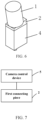
- FIG. 6 is a schematic assembly diagram of a camera apparatus according to other embodiments of the present disclosure.
- the camera apparatus may include a lens 1, a camera 4, and a connecting module disposed between the camera and the lens.
- the connecting module includes a first connecting piece 2.
- the first connecting piece 2 is configured to implement fastening to the lens and fastening to the camera.
- An upper surface of the first connecting piece 2 is the lens connecting surface, and a lower surface of the first connecting piece 2 is the camera connecting surface.
- the connecting module includes just the first connecting piece 2. The upper and lower surfaces of the first connecting piece 2 are inclined.
- the first connecting piece 2 serves to implement fastening between the lens and the camera, and, by causing the angle between the upper surface and the lower surface of the first connecting piece 2 to be equal to the predetermined angle, make the overall inclination of the connecting module satisfy the predetermined angle.
- the embodiment shown in FIG. 6 reduces the number of connecting pieces.
- the first connecting piece 2 may be directly connected to the camera 4 by small screw holes, threads, and screws around the through-hole.
- the correspondence between the two different working planes during imaging of the camera depends on an angle at which the camera is staggered from the lens by a link mechanism between the camera and the lens.
- the correspondence between the two different working planes during imaging of the camera will not change and the mounting position will not be offset due to external vibration or long-term operation of the camera.
- FIG. 7 is a schematic assembly diagram of a camera apparatus according to still other embodiments of the present disclosure.
- the camera apparatus further includes a camera control device 5.
- the camera control device 5 is connected to the first connecting piece 2.
- the angle between the upper surface and the lower surface of the first connecting piece 2 is adjustable.
- the camera apparatus further includes a camera control device.
- the camera control device 5 is configured to obtain a positional relationship between a first detection region and a second detection region, determine the predetermined angle and a target position based on the positional relationship between the first detection region and the second detection region, adjust the angle between the upper surface and the lower surface of the first connecting piece 2 to the predetermined angle, and mount the camera apparatus to the target position.
- an angle between the upper surface and the lower surface of the first connecting piece 2 is adjustable.
- the camera apparatus further includes a camera control device.
- the camera control device determines the predetermined angle and a target position based on the positional relationship between the first detection region and the second detection region, adjusts the camera apparatus to satisfy the predetermined angle, and mounts the camera apparatus to the target position. In this way, the predetermined angle can be satisfied through adjustment based on the positional relationship between the first detection region and the second detection region.
- a specified structure may be used to implement adjustability of the angle between the upper surface and the lower surface of the first connecting piece 2.
- a specified structure may be used to implement adjustability of the angle between the lens connecting surface and the camera connecting surface of the connecting module.
- the connecting module (a link mechanism) between the single camera and the lens may be an adjustable mechanism. Adaptivity can be achieved through adjustment based on different diameters of the winding needle.
- the angle range of the predetermined angle may be 0 to 20 degrees.
- the camera apparatus further includes a camera control device 5.
- the camera control device 5 is connected to the first connecting piece 2.
- the camera control device 5 may be configured to instruct a manufacturing device to prepare beforehand a plurality of first connecting pieces 2 of which the upper surfaces are at different angles to the lower surfaces, obtain a positional relationship between a first detection region and a second detection region, determine the predetermined angle and a target position based on the positional relationship between the first detection region and the second detection region, select a first connecting piece 2 with an angle between an upper surface and a lower surface equal to the predetermined angle as a first connecting piece 2 to be applied, and mount the camera apparatus to the target position.
- a plurality of first connecting pieces 2 of which the upper surfaces are at different angles to the lower surfaces can be prepared beforehand.
- the camera control device determines the predetermined angle and the target position based on the positional relationship between the first detection region and the second detection region, selects a first connecting piece 2 with an angle between the upper surface and the lower surface being equal to the predetermined angle, uses the first connecting piece 2 as a first connecting piece to be applied, and relocates the camera apparatus to the target position.
- the angle range of the predetermined angle may be 0 to 20 degrees.
Landscapes
- Engineering & Computer Science (AREA)
- Chemical & Material Sciences (AREA)
- General Physics & Mathematics (AREA)
- Physics & Mathematics (AREA)
- Pathology (AREA)
- Life Sciences & Earth Sciences (AREA)
- Health & Medical Sciences (AREA)
- Analytical Chemistry (AREA)
- Biochemistry (AREA)
- General Health & Medical Sciences (AREA)
- Immunology (AREA)
- Signal Processing (AREA)
- Electrochemistry (AREA)
- Manufacturing & Machinery (AREA)
- Chemical Kinetics & Catalysis (AREA)
- General Chemical & Material Sciences (AREA)
- Textile Engineering (AREA)
- Multimedia (AREA)
- Computer Vision & Pattern Recognition (AREA)
- Studio Devices (AREA)
- Camera Bodies And Camera Details Or Accessories (AREA)
- Lenses (AREA)
- Cameras In General (AREA)
- Details Of Cameras Including Film Mechanisms (AREA)
Description
- The present disclosure relates to the technical field of battery manufacturing, and in particular, to a camera apparatus and a winder system.
- In a process of winding webs on a battery winder to manufacture a battery cell, winding positions of a positive electrode plate, a negative electrode plate, a first separator, and a second separator in each layer of web needs to be detected. In a case that the winding positions are out of a specified position, an alarm is raised, and the battery cell is discarded. Misalignment between the electrode plate and the separator needs to be monitored on the winder in real time by using a CCD (Charge-coupled Device, charge-coupled device), and a calculation result is fed back to a host computer software to ensure that indicators such as key dimensions of the battery cell satisfy production standards.
- In the related art, features of the positive electrode plate and the negative electrode plate need to be captured by two independent cameras. In a case that a relative position or angle between the two cameras is changed due to continuous vibration of a stand in a long production process, positions of the features to be detected in the image may be offset accordingly, and accumulated errors increase progressively.
-
CN 112 311 971 A relates to the technical field of monitoring equipment, in particular to a camera and a monitoring system. The camera includes: a housing having a camera front cover; a camera lens arranged on the camera front cover; and a sensor fixing plate arranged on the camera front cover corresponding to the camera lens, wherein the sensor fixing plate is provided with a sensor mounting surface used for mounting a sensor. An angle formed between the sensor mounting surface and the lens plane of the camera lens is smaller than or equal to 5 degrees. In actual use, the angle between the sensor mounting surface and the optical axis center line of the camera lens is adjusted as required, so that the positional relationship among the image plane of the camera, the lens plane and the main body plane meets the Scheimpflug principle; therefore, the figure or object image of the object plane observed by the camera can be clearly imaged on the imaging surface of the camera, the optimal recognition effect is obtained, and the monitoring requirement is met. - Technical solution in the related art may also require two independent cameras to work in relation to each other.
CN 112 229 846 A describes for example a pole piece winding coverage detection method and device. The method comprises the steps of respectively collecting an image of a first side surface of a negative pole piece and an image of a positive pole piece through a first image collection device after the winding of the negative pole piece and during the winding of the positive pole piece, and obtaining a head sideline of the head paste coating of the first side surface of the negative pole piece and a head side line of the head paste coating of the positive pole piece, and determining a first coverage length. The pole piece image is acquired and processed through the image acquisition device and the image processing device to obtain the head covering length of the roll core. - In view of the foregoing problems, the present disclosure provides a winder system with a camera apparatus according to claim 1 so that positive electrode features and negative electrode features can be captured with a single camera.
- According to a first aspect, the present disclosure provides a winder system with a camera apparatus including: a camera and a lens, where an angle between a sensor target plane of the camera and a lens plane of the lens is a predetermined angle, and an angle value of the predetermined angle is greater than 0 degree and less than or equal to 20 degrees.
- In the technical solution of embodiments of the present disclosure, in a winding process of a battery winder, a positive feature detection region and a negative electrode feature detection region are on different working planes. A distance (such as 100 mm) between the different working planes is far greater than a depth of field (such as 5 to 15 mm) of a conventional camera. In this case, a single camera in a conventional solution is unable to concurrently obtain clear images of both the positive electrode features and the negative electrode features. Because the angle between the sensor target plane of the camera and the lens plane of the lens according to the foregoing embodiment of the present disclosure is a predetermined angle, the camera apparatus can implement focusing of images on different working planes, thereby obtaining clear images of both positive electrode features and negative electrode features concurrently with a single camera.
- The camera apparatus is mounted at a target position with respect to a battery winder, and is configured to obtain image information of a first detection region and image information of a second detection region concurrently. The target position is determined based on the predetermined angle. The battery winder is configured to wind the positive electrode plate of a battery and a negative electrode plate of the battery. The image information of the first detection region includes positive electrode features of the positive electrode plate, and the image information of the second detection region includes negative electrode features of the negative electrode plate. The target position of the camera apparatus with respect to the winder and the predetermined angle of the camera apparatus enable the camera apparatus to concurrently obtain clear images of both the positive electrode features and the negative electrode features.
- In some embodiments, the predetermined angle and the target position make the first detection region and the second detection region concurrently satisfy a Gaussian imaging formula. According to the present disclosure, through gradual adjustment, the camera apparatus is mounted at the target position with respect to the battery winder. The first detection region and the second detection region can concurrently satisfy the Gaussian imaging formula in a novel optical imaging mode by adjusting a back focal length, thereby implementing focusing of images on different working planes.
- In some embodiments, that the first detection region and the second detection region concurrently satisfy the Gaussian imaging formula is: a distance between the first detection region and a center of the lens plane of the lens, a distance between the center of the lens plane of the lens and a first imaging point of the sensor target plane of the camera, and a focal length of the lens satisfy the Gaussian imaging formula; and concurrently, a distance between the second detection region and the center of the lens plane of the lens, a distance between the center of the lens plane of the lens and a second imaging point of the sensor target plane of the camera, and the focal length of the lens satisfy the Gaussian imaging formula.
- In some embodiments, the camera apparatus further includes: a connecting module disposed between the camera and the lens, where the connecting module is configured to implement fastening between the camera and the lens. The present disclosure implements the fastening between the camera and the lens through the connecting module. In this way, the present disclosure can use just a single camera to capture the positive electrode features and the negative electrode features. In addition, the connecting module in hardware design prevents the relative position between the positive electrode plate and the negative electrode plate from being offset by continuous vibration of a stand in a long production process.
- In some embodiments, the connecting module includes a lens connecting surface and a camera connecting surface. The lens connecting surface is a connecting surface between the connecting module and the lens. The camera connecting surface is a connecting surface between the connecting module and the camera. An angle between the lens connecting surface and the camera connecting surface is equal to the predetermined angle. In the present disclosure, the angle between the lens connecting surface and the camera connecting surface of the connecting module is set to be the predetermined angle. In this way, during fastening between the camera and the lens, the angle between the sensor target plane of the camera and the lens plane of the lens can be fixedly set to be the predetermined angle.
- In some embodiments, the connecting module includes a first connecting piece and a second connecting piece. The first connecting piece is configured to implement fastening to the lens and fastening to the second connecting piece. The second connecting piece is configured to implement fastening to the camera. An upper surface of the first connecting piece is the lens connecting surface, a lower surface of the first connecting piece is connected to an upper surface of the second connecting piece, and a lower surface of the second connecting piece is the camera connecting surface. In some of the foregoing embodiments of the present disclosure, the connecting module includes a first connecting piece and a second connecting piece. The lens can be fastened to the camera more conveniently by the two connecting pieces.
- In some embodiments, the angle between the upper surface of the first connecting piece and the lower surface of the first connecting piece is equal to the predetermined angle. The upper surface of the second connecting piece is parallel to the lower surface of the second connecting piece. In some embodiments of the present disclosure, the upper and lower surfaces of the first connecting piece may be inclined. To be specific, the first connecting piece serves to implement fastening between the lens and the second connecting piece, and, by causing the angle between the upper surface and the lower surface of the first connecting piece to be equal to the predetermined angle, make the overall inclination of the connecting module satisfy the predetermined angle. In some embodiments of the present disclosure, the second connecting piece serves to implement fastening between the first connecting piece and the camera.
- In some embodiments, the connecting module includes a first connecting piece. The first connecting piece is configured to implement fastening to the lens and fastening to the camera. An upper surface of the first connecting piece is the lens connecting surface, and a lower surface of the first connecting piece is the camera connecting surface. In some embodiments of the present disclosure, the connecting module includes just the first connecting piece. The upper and lower surfaces of the first connecting piece are inclined. To be specific, the first connecting piece serves to implement fastening between the lens and the camera, and, by causing the angle between the upper surface and the lower surface of the first connecting piece to be equal to the predetermined angle, make the overall inclination of the connecting module satisfy the predetermined angle.
- In some embodiments, an angle between the upper surface and the lower surface of the first connecting piece is adjustable. The camera apparatus further includes a camera control device. The camera control device is configured to obtain a positional relationship between a first detection region and a second detection region, determine the predetermined angle and a target position based on the positional relationship between the first detection region and the second detection region, adjust the angle between the upper surface and the lower surface of the first connecting piece to the predetermined angle, and mount the camera apparatus to the target position. In some embodiments of the present disclosure, an angle between the upper surface and the lower surface of the first connecting piece is adjustable. The camera apparatus further includes a camera control device. The camera control device determines the predetermined angle and a target position based on the positional relationship between the first detection region and the second detection region, adjusts the camera apparatus to satisfy the predetermined angle, and mounts the camera apparatus to the target position. In this way, the predetermined angle can be satisfied through adjustment based on the positional relationship between the first detection region and the second detection region.
- In some embodiments, the camera apparatus further includes a camera control device. The camera control device is configured to instruct a manufacturing device to prepare beforehand a plurality of first connecting pieces of which the upper surfaces are at different angles to the lower surfaces, obtain a positional relationship between a first detection region and a second detection region, determine the predetermined angle and a target position based on the positional relationship between the first detection region and the second detection region, select a first connecting piece with an angle between an upper surface and a lower surface equal to the predetermined angle as a first connecting piece to be applied, and mount the camera apparatus to the target position. In some embodiments of the present disclosure, a plurality of first connecting pieces of which the upper surfaces are at different angles to the lower surfaces are prepared beforehand. The camera apparatus further includes a camera control device. The camera control device determines the predetermined angle and a target position based on the positional relationship between the first detection region and the second detection region, selects a first connecting piece with an angle between the upper surface and the lower surface being equal to the predetermined angle, uses the first connecting piece as a first connecting piece to be applied, and relocates the camera apparatus to the target position. In this way, based on the positional relationship between the first detection region and the second detection region, the first connecting piece with a different predetermined angle can be selected for adapting to actual needs.
- The present disclosure provides the winder system, including the battery winder and the camera apparatus according to any one of the embodiments described above.
- To describe the technical solutions in the embodiments of the present disclosure more clearly, the following outlines the drawings used in the embodiments of the present disclosure. Evidently, the drawings outlined below are merely a part of embodiments of the present disclosure. A person of ordinary skill in the art may derive other drawings from the outlined drawings without making any creative efforts.
-
FIG. 1 is a schematic structural diagram of a winder system according to some embodiments of the present disclosure; -
FIG. 2 is a schematic diagram of a winder system according to other embodiments of the present disclosure; -
FIG. 3 is a schematic diagram of visual imaging of a lens in a camera apparatus according to some embodiments of the present disclosure; -
FIG. 4 is a schematic assembly diagram of a camera apparatus according to some embodiments of the present disclosure; -
FIG. 5 is a three-dimensional exploded view of a camera apparatus according to some embodiments of the present disclosure; -
FIG. 6 is a schematic assembly diagram of a camera apparatus according to other embodiments of the present disclosure; and -
FIG. 7 is a schematic assembly diagram of a camera apparatus according to still other embodiments of the present disclosure. - The drawings are not drawn to scale.
- Reference numerals:
-
vehicle 1000; -
battery winder 100,camera apparatus 200,first detection region 300,second detection region 400,negative electrode plate 500,positive electrode plate 600,first separator 700,second separator 800; -
camera 4,lens 1, first connectingpiece 2, second connectingpiece 3,camera control device 5; - camera
sensor target plane 41,lens plane 11; -
lens plane center 111,first imaging point 411 of the sensor target plane of the camera,second imaging point 411 of the sensor target plane of the camera. - Embodiments of the technical solutions of the present disclosure are described in detail below with reference to the drawings. The following embodiments are merely intended to describe the technical solutions of the present disclosure more clearly, and are merely exemplary but without hereby limiting the protection scope of the present disclosure, which is defined by the appended claims.
- Unless otherwise defined, all technical and scientific terms used herein have the same meanings as usually understood by a person skilled in the technical field of the present disclosure. The terms used herein are merely intended for describing specific embodiments but are not intended to limit the present disclosure. The terms "include" and "contain" and any variations thereof used in the specification, claims, and brief description of drawings of the present disclosure are intended as non-exclusive inclusion.
- In the description of the embodiments of the present disclosure, the technical terms "first" and "second" are merely intended to distinguish between different items but not intended to indicate or imply relative importance or implicitly specify the number of the indicated technical features, the specific order, or order of precedence. In the description of the embodiments of the present disclosure, unless otherwise expressly specified, "a plurality of" means two or more.
- Reference to "embodiment" herein means that a specific feature, structure or characteristic described with reference to the embodiment may be included in at least one embodiment of the present disclosure. Reference to this term in different places in the specification does not necessarily represent the same embodiment, nor does it represent an independent or alternative embodiment in a mutually exclusive relationship with other embodiments. A person skilled in the art explicitly and implicitly understands that the embodiments described herein may be combined with other embodiments.
- In the description of embodiments of the present disclosure, the term "and/or" merely indicates a relationship between related items, and represents three possible relationships. For example, "A and/or B" may represent the following three circumstances: A alone, both A and B, and B alone. In addition, the character "/" herein generally indicates an "or" relationship between the item preceding the character and the item following the character.
- In the description of embodiments of the present disclosure, the term "a plurality of" means two or more (including two). Similarly, "a plurality of groups" means two or more groups (including two groups), and "a plurality of pieces" means two or more pieces (including two pieces).
- In the description of embodiments of the present disclosure, a direction or a positional relationship indicated by the terms such as "center", "longitudinal", "transverse", "length", "width", "thickness", "up", "down", "before", "after", "left", "right", "vertical", "horizontal", "top", "bottom", "in", "out", "clockwise", "counterclockwise", "axial", "radial", and "circumferential" is a direction or positional relationship based on the illustration in the drawings, and is merely intended for ease or brevity of description of embodiments of the present disclosure, but not intended to indicate or imply that the indicated device or component is necessarily located in the specified direction or constructed or operated in the specified direction. Therefore, such terms are not to be understood as a limitation on embodiments of the present disclosure.
- In the description of embodiments of the present disclosure, unless otherwise expressly specified and qualified, the technical terms such as "mounting", "concatenation", "connection", and "fixing" need to be understood in a broad sense, for example, understood as a fixed connection or a detachable connection or understood as being integrated into a whole; or understood be as a mechanical connection or an electrical connection, a direct connection or an indirect connection implemented through an intermediary; or understood as interior communication between two components or interaction between two components. A person of ordinary skill in the art understands the specific meanings of the terms in embodiments of the present disclosure according to the context.
- Currently, in a production process of a lithium-ion battery, a winding process is involved, in which a negative electrode plate, a positive electrode plate, and a separator are wound into a complete half-cell. During the winding, the degree of misalignment between the negative electrode plate, the positive electrode plate, and the separator needs to fall within a range of ±0.5 mm. Beyond that range, the misalignment leaves a battery cell to be at risk of short circuits. The short circuit of the battery cell in use may cause a fire or even explosion. Therefore, the winding process needs to be monitored in real time by using a reliable detection method, so as to avoid pass of a battery cell of substandard dimensions to a subsequent process.
- The inventor is aware that during the winding of a battery cell, the alignment between webs in a first detection region (an in-feed section of the battery cell) and the alignment between webs in a second detection region (a roll section of the battery cell) need to be detected concurrently. The first detection region and the second detection region are located on different working planes. Therefore, the camera apparatus need to focus on different working planes concurrently.
- In the related art, a camera apparatus includes two camera kits: a first camera kit configured to detect the alignment between webs in the in-feed section of the battery cell; and a second camera kit configured to detect the alignment between webs of the roll section of the battery cell. The solution in the related art requires two independent cameras that work in relation to each other to detect the alignment of the positive and negative electrode plates of the battery cell.
- The inventor is aware that the technical solution in the related art requires two independent cameras to work in relation to each other. In a case that a relative position or angle between the two cameras is changed due to continuous vibration of a stand in a long production process, positions of the features to be detected in the image may be offset accordingly, and accumulated errors increase progressively. In such a technical solution, the steadiness of the camera on the vibrating stand is not ensured. In other words, the solution that relies on calibration of a coordinate system between two cameras is inherently at high risk of unsteadiness. In view of the problem above, the present disclosure aims to design a camera structure that is steady in structure and capable of using a single camera to capture features of the positive and negative electrode plates.
- The inventor is also aware that another technical solution in the related art is to capture the features of the positive and negative electrode plates with a single camera on condition that the winder uses a prismatic winding needle. However, this technical solution is applicable only to prismatic winding needles where an in-feed position and a winding position are on the same working plane, but not applicable to circular winding needles (in most existing machine models, the in-feed position and the winding position are not on the same working plane). In this technical solution, a tension of a prismatic winding needle changes periodically during the winding, being adverse to steadiness of a winding product.
- Therefore, it is necessary to design a camera apparatus that is steady in structure and capable of using a single camera to capture features of positive and negative electrode plates where the in-feed position and the winding position are not on the same working plane.
- For ease of description, the following describes some embodiments of the present disclosure using a winder system applicable to a production process of batteries as an example.
- Referring to
FIG. 1, FIG. 1 is a schematic structural diagram of a winder system according to some embodiments of the present disclosure. Thewinder system 1000 includes abattery winder 100 and acamera apparatus 200. A winding needle of thebattery winder 100 is a circular winding needle. A first detection region and a second detection region are located on different working planes. Therefore, the camera apparatus need to focus on different working planes concurrently. - In some embodiments of the present disclosure, the winding needle of the winder system according to the present disclosure may be a prismatic winding needle or an elliptical winding needle instead.
- The
battery winder 100 is configured to wind a positive electrode plate and a negative electrode plate of a battery. - The
camera apparatus 200 is configured to detect and obtain image information of thefirst detection region 300 and image information of thesecond detection region 400. The image information of thefirst detection region 300 is image information of each web in an in-feed section of a battery cell. The image information of thesecond detection region 400 is image information of each web in a roll section of the battery cell. As shown inFIG. 2 , each layer of web includes anegative electrode plate 500, apositive electrode plate 600, afirst separator 700, and asecond separator 800. - According to the claimed invention as shown in
FIG. 1 , the image information of thefirst detection region 300 includes positive electrode features of the positive electrode plate. The image information of thesecond detection region 400 includes negative electrode features of the negative electrode plate. - Referring to
FIG. 2, FIG. 2 is a schematic diagram of a winder system according to other embodiments of the present disclosure. Thewinder system 1000 includes abattery winder 100 and acamera apparatus 200. As shown inFIG. 2 , the camera apparatus according to the present disclosure may include: acamera 4 and alens 1. An angle between asensor target plane 41 of thecamera 4 and alens plane 11 of thelens 1 is a predetermined angle. An angle value of the predetermined angle is greater than 0 degree and less than or equal to 20 degrees. - In the technical solution of embodiments of the present disclosure, in a winding process of the battery winder, a positive feature detection region and a negative electrode feature detection region are on different working planes. A distance between the different working planes is far greater than a depth of field of a conventional camera. In this case, a single camera in a conventional solution is unable to concurrently obtain clear images of both the positive electrode features and the negative electrode features. However, according to the foregoing embodiments of the present disclosure, the angle between the sensor target plane of the camera and the lens plane of the lens is set to satisfy a predetermined angle. In this way, the camera apparatus according to the foregoing embodiments of the present disclosure can implement focusing of images on different working planes, thereby obtaining clear images of both positive electrode features and negative electrode features concurrently with a single camera.
- In some embodiments, as shown in
FIG. 1 andFIG. 2 , thecamera apparatus 200 is mounted at a target position with respect to abattery winder 100, and is configured to obtain image information of a first detection region and image information of a second detection region concurrently. The target position is determined based on the predetermined angle. The battery winder is configured to wind the positive electrode plate of a battery and a negative electrode plate of the battery. The image information of the first detection region includes positive electrode features of the positive electrode plate, and the image information of the second detection region includes negative electrode features of the negative electrode plate. The target position of the camera apparatus with respect to the winder and the predetermined angle of the camera apparatus enable the camera apparatus to concurrently obtain clear images of both the positive electrode features and the negative electrode features. - In some embodiments of the present disclosure, a working distance between the
camera apparatus 200 and thebattery winder 100 may be 260 mm; and a distance between thecamera apparatus 200 and a winding mandrel in a vertical direction (a height direction) may be 40 mm. - In some embodiments of the present disclosure, an imaging precision of the camera apparatus for the first detection region may be 0.03 mm/px, and an imaging precision of the camera apparatus for the second detection region may be 0.023 mm/px.
- In some embodiments, as shown in
FIG. 2 , the predetermined angle and the target position make the first detection region and the second detection region concurrently satisfy a Gaussian imaging formula. According to the present disclosure, through gradual adjustment, the camera apparatus is mounted at the target position with respect to the battery winder. The first detection region and the second detection region can concurrently satisfy the Gaussian imaging formula in a novel optical imaging mode by adjusting a back focal length, thereby implementing focusing of images on different working planes. - Referring to
FIG. 3, FIG. 3 is a schematic diagram of visual imaging of a lens in a camera apparatus according to some embodiments of the present disclosure. As shown inFIG. 3 , a distance S1' between thefirst detection region 300 and acenter 111 of the lens plane of the lens, a distance S2' between thecenter 111 of the lens plane of the lens and afirst imaging point 411 of the sensor target plane of the camera, and a focal length f of the lens satisfy the Gaussian imaging formula, as shown in formula (1) below; and concurrently, adistance S 1" between the second detection region and thecenter 111 of the lens plane of the lens, a distance S2" between thecenter 111 of the lens plane of the lens and asecond imaging point 412 of the sensor target plane of the camera, and the focal length f of the lens satisfy the Gaussian imaging formula, as shown in formula (2) below.

- The specified angle between the sensor target plane of the camera and the lens plane of the lens according to the foregoing embodiments of the present disclosure enables the first detection region and the second detection region to concurrently satisfy the Gaussian imaging formula, thereby implementing focusing of images on different working planes.
- In the foregoing embodiments of the present disclosure, when the same convex lens needs to perform imaging at different object distances, the focusing and imaging at different working distances can be implemented by adjusting a back focal length.
- The novel optical imaging mode according to the foregoing embodiments of the present disclosure can implement focusing of images on different working planes.
- The foregoing embodiments of the present disclosure are adaptable to a circular winding needle. The production capacity of circular winding needles is 2 to 3 times that of prismatic winding needles. For example, the production capacity of circular winding needles is 3 times that of prismatic or oval winding needles, the winding speed of the prismatic or oval winding needles is 600 to 700 mm/s, and the winding speed of circular winding needles is 2000 to 2500 mm/s.
- In some embodiments, the camera apparatus further includes: a connecting module disposed between the camera and the lens, where the connecting module is configured to implement fastening between the camera and the lens. The present disclosure implements the fastening between the camera and the lens through the connecting module. In this way, the present disclosure can use just a single camera to capture the positive electrode features and the negative electrode features. In addition, the connecting module in hardware design prevents the relative position between the positive electrode plate and the negative electrode plate from being offset by continuous vibration of a stand in a long production process.
- In some embodiments, the connecting module includes a lens connecting surface and a camera connecting surface. The lens connecting surface is a connecting surface between the connecting module and the lens. The camera connecting surface is a connecting surface between the connecting module and the camera. An angle between the lens connecting surface and the camera connecting surface is equal to the predetermined angle. In the present disclosure, the angle between the lens connecting surface and the camera connecting surface of the connecting module is set to be the predetermined angle. In this way, during fastening between the camera and the lens, the angle between the sensor target plane of the camera and the lens plane of the lens can be fixedly set to be the predetermined angle.
- Referring to
FIG. 4 and FIG. 5, FIG. 4 is a schematic assembly diagram of a camera apparatus according to some embodiments of the present disclosure.FIG. 5 is a three-dimensional exploded view of a camera apparatus according to some embodiments of the present disclosure. In some embodiments, as shown inFIG. 4 and FIG. 5 , the camera apparatus may include alens 1, acamera 4, and a connecting module disposed between the camera and the lens. The connecting module includes a first connectingpiece 2 and a second connectingpiece 3. The first connectingpiece 2 is configured to implement fastening to thelens 1 and fastening to the second connectingpiece 3. The second connectingpiece 3 is configured to implement fastening to thecamera 4. An upper surface of the first connectingpiece 2 is the lens connecting surface, a lower surface of the first connectingpiece 2 is connected to an upper surface of the second connectingpiece 3, and a lower surface of the second connectingpiece 3 is the camera connecting surface. In some of the foregoing embodiments of the present disclosure, the connecting module includes a first connectingpiece 2 and a second connectingpiece 3. The lens can be fastened to the camera more conveniently by the two connecting pieces. - In some embodiments, as shown in
FIG. 4 and FIG. 5 , the angle between the upper surface of the first connectingpiece 2 and the lower surface of the first connectingpiece 2 is equal to the predetermined angle. The upper surface of the second connectingpiece 3 is parallel to the lower surface of the second connectingpiece 3. In some embodiments of the present disclosure, the upper and lower surfaces of the first connectingpiece 2 may be inclined. To be specific, the first connectingpiece 2 serves to implement fastening between the lens and the second connectingpiece 3, and, by causing the angle between the upper surface and the lower surface of the first connectingpiece 2 to be equal to the predetermined angle, make the overall inclination of the connecting module satisfy the predetermined angle. In some embodiments of the present disclosure, the second connectingpiece 3 serves to implement fastening between the first connectingpiece 2 and thecamera 4. In some embodiments of the present disclosure, the second connectingpiece 3 primarily serves as an intermediate hub between the first connectingpiece 2 and thecamera 4. - In some embodiments, as shown in
FIG. 4 and FIG. 5 , an external thread of thelens 1 is fastened by an internal thread of the first connectingpiece 2. The first connectingpiece 2 is fastened to the second connectingpiece 3 by small screw holes, threads, and screws around a through-hole. The second connectingpiece 3 is fastened to thecamera 4 by small screw holes, threads, and screws around the through-hole. - In the foregoing embodiments of the present disclosure, just a single camera is required to capture the positive and negative electrode features. The hardware design according to the foregoing embodiments of the present disclosure prevents the relative position between the positive electrode plate and the negative electrode plate from being offset by continuous vibration of a stand in a long production process.
- The novel optical imaging mode implemented by adjusting the back focal length according to the foregoing embodiments of the present disclosure can implement focusing of images on different working planes. The correspondence between the two working planes in the foregoing embodiments of the present disclosure keeps steady and unchanged.
- Referring to
FIG. 6, FIG. 6 is a schematic assembly diagram of a camera apparatus according to other embodiments of the present disclosure. In some embodiments, as shown inFIG. 6 , the camera apparatus may include alens 1, acamera 4, and a connecting module disposed between the camera and the lens. The connecting module includes a first connectingpiece 2. The first connectingpiece 2 is configured to implement fastening to the lens and fastening to the camera. An upper surface of the first connectingpiece 2 is the lens connecting surface, and a lower surface of the first connectingpiece 2 is the camera connecting surface. In some embodiments of the present disclosure, the connecting module includes just the first connectingpiece 2. The upper and lower surfaces of the first connectingpiece 2 are inclined. To be specific, the first connectingpiece 2 serves to implement fastening between the lens and the camera, and, by causing the angle between the upper surface and the lower surface of the first connectingpiece 2 to be equal to the predetermined angle, make the overall inclination of the connecting module satisfy the predetermined angle. - Compared with the embodiments shown in
FIG. 4 and FIG. 5 , the embodiment shown inFIG. 6 reduces the number of connecting pieces. In some embodiments, as shown inFIG. 6 , on condition that the design of the first connectingpiece 2 is complex enough, the first connectingpiece 2 may be directly connected to thecamera 4 by small screw holes, threads, and screws around the through-hole. - According to the foregoing embodiments of the present disclosure, the correspondence between the two different working planes during imaging of the camera depends on an angle at which the camera is staggered from the lens by a link mechanism between the camera and the lens.
- According to the foregoing embodiments of the present disclosure, the correspondence between the two different working planes during imaging of the camera will not change and the mounting position will not be offset due to external vibration or long-term operation of the camera.
- Referring to
FIG. 7, FIG. 7 is a schematic assembly diagram of a camera apparatus according to still other embodiments of the present disclosure. As shown inFIG. 7 , the camera apparatus further includes acamera control device 5. Thecamera control device 5 is connected to the first connectingpiece 2. The angle between the upper surface and the lower surface of the first connectingpiece 2 is adjustable. The camera apparatus further includes a camera control device. Thecamera control device 5 is configured to obtain a positional relationship between a first detection region and a second detection region, determine the predetermined angle and a target position based on the positional relationship between the first detection region and the second detection region, adjust the angle between the upper surface and the lower surface of the first connectingpiece 2 to the predetermined angle, and mount the camera apparatus to the target position. In the foregoing embodiments of the present disclosure, an angle between the upper surface and the lower surface of the first connectingpiece 2 is adjustable. The camera apparatus further includes a camera control device. The camera control device determines the predetermined angle and a target position based on the positional relationship between the first detection region and the second detection region, adjusts the camera apparatus to satisfy the predetermined angle, and mounts the camera apparatus to the target position. In this way, the predetermined angle can be satisfied through adjustment based on the positional relationship between the first detection region and the second detection region. - According to the foregoing embodiments of the present disclosure, a specified structure may be used to implement adjustability of the angle between the upper surface and the lower surface of the first connecting
piece 2. Alternatively, according to the foregoing embodiments of the present disclosure, a specified structure may be used to implement adjustability of the angle between the lens connecting surface and the camera connecting surface of the connecting module. - According to the foregoing embodiments of the present disclosure, the connecting module (a link mechanism) between the single camera and the lens may be an adjustable mechanism. Adaptivity can be achieved through adjustment based on different diameters of the winding needle. The angle range of the predetermined angle may be 0 to 20 degrees.
- In other embodiments of the present disclosure, as shown in
FIG. 7 , the camera apparatus further includes acamera control device 5. Thecamera control device 5 is connected to the first connectingpiece 2. Thecamera control device 5 may be configured to instruct a manufacturing device to prepare beforehand a plurality of first connectingpieces 2 of which the upper surfaces are at different angles to the lower surfaces, obtain a positional relationship between a first detection region and a second detection region, determine the predetermined angle and a target position based on the positional relationship between the first detection region and the second detection region, select a first connectingpiece 2 with an angle between an upper surface and a lower surface equal to the predetermined angle as a first connectingpiece 2 to be applied, and mount the camera apparatus to the target position. - In this way, in the foregoing embodiments of the present disclosure, a plurality of first connecting
pieces 2 of which the upper surfaces are at different angles to the lower surfaces can be prepared beforehand. The camera control device determines the predetermined angle and the target position based on the positional relationship between the first detection region and the second detection region, selects a first connectingpiece 2 with an angle between the upper surface and the lower surface being equal to the predetermined angle, uses the first connectingpiece 2 as a first connecting piece to be applied, and relocates the camera apparatus to the target position. In this way, in the foregoing embodiments of the present disclosure, depending on different diameters of the winding needle, the first connecting pieces with different angles can be selected to achieve adaptivity. The angle range of the predetermined angle may be 0 to 20 degrees. - Although the present disclosure has been described with reference to exemplary embodiments, various improvements may be made to the embodiments without departing from the scope of the present disclosure, and the components of the present disclosure may be replaced with equivalents. Particularly, to the extent that no structural conflict exists, various technical features mentioned in various embodiments can be combined in any manner. The present disclosure is not limited to the specific embodiments disclosed herein, but includes all technical solutions falling within the scope of protection as defined by the appended claims.
Claims (10)
- A winder system (1000), comprising a battery winder (100) and a camera apparatus (200) with a camera (4) and a lens (1), wherein an angle between a sensor target plane of the camera (4) and a lens plane (11) of the lens (1) is a predetermined angle, and an angle value of the predetermined angle is greater than 0 degree and less than or equal to 20 degrees, wherein the camera apparatus (200) is mounted at a target position with respect to the battery winder (100), and is configured to obtain image information of a first detection region (300) and image information of a second detection region (400) concurrently, the target position is determined based on the predetermined angle, the battery winder (100) is configured to wind a positive electrode plate (600) of a battery and a negative electrode plate (500) of the battery, the image information of the first detection region (300) comprises positive electrode features of the positive electrode plate (600), and the image information of the second detection region (400) comprises negative electrode features of the negative electrode plate (500).
- The winder system (1000) according to claim 1, wherein the predetermined angle and the target position make the first detection region (300) and the second detection region (400) concurrently satisfy a Gaussian imaging formula.
- The winder system (1000) according to claim 2, wherein, that the first detection region (300) and the second detection region (400) concurrently satisfy the Gaussian imaging formula is: a distance between the first detection region (300) and a center of the lens plane (11) of the lens (1), a distance between the center of the lens plane (11) of the lens (1) and a first imaging point of the sensor target plane of the camera (4), and a focal length of the lens (1) satisfy the Gaussian imaging formula; and concurrently, a distance between the second detection region (400) and the center of the lens plane (11) of the lens (1), a distance between the center of the lens plane (11) of the lens (1) and a second imaging point of the sensor target plane of the camera (4), and the focal length of the lens (1) satisfy the Gaussian imaging formula.
- The winder system (1000) according to claim 1, further comprising: a connecting module disposed between the camera (4) and the lens (1), wherein the connecting module is configured to implement fastening between the camera (4) and the lens (1).
- The winder system (1000) according to claim 4, wherein the connecting module comprises a lens connecting surface and a camera connecting surface, the lens connecting surface is a connecting surface between the connecting module and the lens (1), the camera connecting surface is a connecting surface between the connecting module and the camera (4), and an angle between the lens connecting surface and the camera connecting surface is equal to the predetermined angle.
- The winder system (1000) according to claim 5, wherein the connecting module comprises a first connecting piece (2) and a second connecting piece (3), the first connecting piece (2) is configured to implement fastening to the lens (1) and fastening to the second connecting piece (3), and the second connecting piece (3) is configured to implement fastening to the camera (4); and, an upper surface of the first connecting piece (2) is the lens connecting surface, a lower surface of the first connecting piece (2) is connected to an upper surface of the second connecting piece (3), and a lower surface of the second connecting piece (3) is the camera connecting surface.
- The winder system (1000) according to claim 6, wherein the angle between the upper surface of the first connecting piece (2) and the lower surface of the first connecting piece (2) is equal to the predetermined angle; and the upper surface of the second connecting piece (3) is parallel to the lower surface of the second connecting piece (3).
- The winder system (1000) according to claim 5, wherein the connecting module comprises a first connecting piece (2), the first connecting piece (2) is configured to implement fastening to the lens (1) and fastening to the camera (4), an upper surface of the first connecting piece (2) is the lens connecting surface, and a lower surface of the first connecting piece (2) is the camera connecting surface.
- The winder system (1000) according to any one of claims 6 to 8, wherein an angle between the upper surface and the lower surface of the first connecting piece (2) is adjustable, the camera apparatus (200) further comprises a camera control device (5), and the camera control device (5) is configured to obtain a positional relationship between the first detection region (300) and the second detection region (400), determine the predetermined angle and the target position based on the positional relationship between the first detection region (300) and the second detection region (400), adjust the angle between the upper surface and the lower surface of the first connecting piece (2) to the predetermined angle, and mount the camera apparatus (200) to the target position.
- The winder system (1000) according to any one of claims 6 to 8, further comprising a camera control device (5), wherein the camera control device (5) is configured to instruct a manufacturing device to prepare beforehand a plurality of first connecting pieces (2) of which upper surfaces are at different angles to lower surfaces, obtain a positional relationship between the first detection region (300) and the second detection region (400), determine the predetermined angle and the target position based on the positional relationship between the first detection region (300) and the second detection region (400), select a first connecting piece (2) with an angle between an upper surface and a lower surface equal to the predetermined angle as a first connecting piece (2) to be applied, and mount the camera apparatus (200) to the target position.
Priority Applications (1)
| Application Number | Priority Date | Filing Date | Title |
|---|---|---|---|
| HUE21925089A HUE068848T2 (en) | 2021-08-31 | 2021-08-31 | Camera apparatus and winder system |
Applications Claiming Priority (1)
| Application Number | Priority Date | Filing Date | Title |
|---|---|---|---|
| PCT/CN2021/115519 WO2023028804A1 (en) | 2021-08-31 | 2021-08-31 | Camera apparatus and winder system |
Publications (4)
| Publication Number | Publication Date |
|---|---|
| EP4166936A1 EP4166936A1 (en) | 2023-04-19 |
| EP4166936A8 EP4166936A8 (en) | 2023-08-09 |
| EP4166936A4 EP4166936A4 (en) | 2023-10-04 |
| EP4166936B1 true EP4166936B1 (en) | 2024-09-04 |
Family
ID=85411866
Family Applications (1)
| Application Number | Title | Priority Date | Filing Date |
|---|---|---|---|
| EP21925089.1A Active EP4166936B1 (en) | 2021-08-31 | 2021-08-31 | Camera apparatus and winder system |
Country Status (6)
| Country | Link |
|---|---|
| US (1) | US12342061B2 (en) |
| EP (1) | EP4166936B1 (en) |
| CN (1) | CN116601483B (en) |
| HU (1) | HUE068848T2 (en) |
| PL (1) | PL4166936T3 (en) |
| WO (1) | WO2023028804A1 (en) |
Families Citing this family (4)
| Publication number | Priority date | Publication date | Assignee | Title |
|---|---|---|---|---|
| KR20230150104A (en) * | 2022-04-21 | 2023-10-30 | 현대자동차주식회사 | Method for battery cell electrode alignment inspection and apparatus thereof |
| IT202300023076A1 (en) * | 2023-11-02 | 2025-05-02 | Manz Italy Srl | METHOD AND SYSTEM FOR QUALITY CONTROL OF A WINDING OF AT LEAST ONE STRIP OF MATERIAL FOR THE MANUFACTURE OF ELECTRIC ENERGY STORAGE DEVICES |
| EP4647715A1 (en) * | 2024-03-12 | 2025-11-12 | Contemporary Amperex Technology Co., Limited | Battery tab misalignment detection method and apparatus, and battery electrode sheet winding system |
| DE102024121962A1 (en) | 2024-08-01 | 2026-02-05 | Mb Automation Gmbh & Co. Kg | Device and method for inspecting stacks of layers |
Family Cites Families (30)
| Publication number | Priority date | Publication date | Assignee | Title |
|---|---|---|---|---|
| SE443457B (en) * | 1983-03-10 | 1986-02-24 | Hasselblad Ab Victor | SYSTEM CAMERA DEVICE |
| US4640598A (en) * | 1985-11-15 | 1987-02-03 | Taichi Yoshida | Power winder attachment for a camera |
| US4816851A (en) * | 1987-01-07 | 1989-03-28 | Canon Kabushiki Kaisha | Motor driven camera |
| JPH0279808A (en) * | 1988-09-16 | 1990-03-20 | Olympus Optical Co Ltd | Camera incorporating swing and tilt mechanism |
| JPH0566628U (en) * | 1991-04-02 | 1993-09-03 | 克臣 松本 | Lens tilt device |
| US5917545A (en) * | 1995-08-31 | 1999-06-29 | Nikon Corporation | Electronic still camera that can be directly inserted in an external device |
| US5899584A (en) * | 1998-06-08 | 1999-05-04 | Eastman Kodak Company | One-time-use camera with film winding motor capable of being disengaged to facilitate film prewinding during camera manufacture |
| JP3738632B2 (en) * | 1999-12-16 | 2006-01-25 | セイコーエプソン株式会社 | Detection data correction method for optical detection means, position detection apparatus provided with optical detection means, and electronic component mounting apparatus |
| JP2001194715A (en) * | 2000-01-12 | 2001-07-19 | Asahi Optical Co Ltd | Adapter equipped with tilt and shift device and camera corresponding to photographing lens |
| US7181133B2 (en) * | 2004-04-01 | 2007-02-20 | Foster Assets Corporation | Camera with film chamber for selective loading of film roll or cartridge and method of selective loading |
| JP4613101B2 (en) * | 2005-06-06 | 2011-01-12 | 矢崎総業株式会社 | Power shut-off device |
| JP5323320B2 (en) * | 2006-07-19 | 2013-10-23 | 有限会社シマテック | Surface inspection device |
| CN203606301U (en) * | 2013-11-20 | 2014-05-21 | 东南大学 | Visual hardware for defect detection of power lithium ion battery pole piece |
| CN104902190A (en) * | 2015-06-24 | 2015-09-09 | 联想(北京)有限公司 | Control method, photographic device and electronic device |
| JP6676573B2 (en) * | 2017-03-29 | 2020-04-08 | Ckd株式会社 | Inspection device and winding device |
| CN207751901U (en) * | 2018-01-30 | 2018-08-21 | 苏州亚相素自动化科技有限公司 | A kind of vision system for the detection of energy-storage battery pole piece appearance |
| CN108344749A (en) * | 2018-02-11 | 2018-07-31 | 凌云光技术集团有限责任公司 | A method of liquid crystal display defect layered weighting is carried out based on two-sided array camera |
| CN109358064B (en) * | 2018-08-31 | 2022-07-08 | 广州超音速自动化科技股份有限公司 | Full-function detection method, equipment, medium and system for pole piece production and winding defects |
| CN110441309B (en) * | 2019-07-08 | 2021-11-02 | 中国科学院上海光学精密机械研究所 | Microscattering polarization imaging surface defect measuring device and measuring method |
| CN112311971A (en) * | 2019-08-01 | 2021-02-02 | 浙江大华技术股份有限公司 | Camera and monitoring system |
| CN111351799A (en) * | 2020-03-11 | 2020-06-30 | 凌云光技术集团有限责任公司 | Imaging device suitable for display screen defect detection |
| CN211785064U (en) * | 2020-03-12 | 2020-10-27 | 杭州利珀科技有限公司 | Material defect detection projection optical system, and defect detection device for web and sheet |
| KR102825957B1 (en) * | 2020-03-16 | 2025-06-26 | 삼성전자주식회사 | Camera module and electronic device including the same |
| CN211601861U (en) * | 2020-03-25 | 2020-09-29 | 无锡先导智能装备股份有限公司 | Detection mechanism |
| CN213340470U (en) * | 2020-09-18 | 2021-06-01 | 江苏时代新能源科技有限公司 | Battery winding system |
| CN112229846B (en) * | 2020-10-14 | 2023-05-16 | 重庆冠宇电池有限公司 | Pole piece winding coverage detection method and equipment |
| CN112738503A (en) * | 2020-12-30 | 2021-04-30 | 凌云光技术股份有限公司 | Device and method for judging and adjusting levelness of small-depth-of-field lens camera |
| CN113218945A (en) * | 2021-04-30 | 2021-08-06 | 博众精工科技股份有限公司 | Chip surface detection device |
| CN113267145B (en) * | 2021-05-12 | 2023-01-17 | 无锡先导智能装备股份有限公司 | Method and device for controlling feeding of pole piece of winding machine, electronic equipment and storage medium |
| CN216833440U (en) * | 2021-09-28 | 2022-06-28 | 上海凯姆视觉科技有限公司 | A vehicle camera system |
-
2021
- 2021-08-31 EP EP21925089.1A patent/EP4166936B1/en active Active
- 2021-08-31 HU HUE21925089A patent/HUE068848T2/en unknown
- 2021-08-31 CN CN202180083965.XA patent/CN116601483B/en active Active
- 2021-08-31 WO PCT/CN2021/115519 patent/WO2023028804A1/en not_active Ceased
- 2021-08-31 PL PL21925089.1T patent/PL4166936T3/en unknown
-
2022
- 2022-12-08 US US18/077,313 patent/US12342061B2/en active Active
Also Published As
| Publication number | Publication date |
|---|---|
| US20230109550A1 (en) | 2023-04-06 |
| HUE068848T2 (en) | 2025-01-28 |
| CN116601483A (en) | 2023-08-15 |
| EP4166936A8 (en) | 2023-08-09 |
| CN116601483B (en) | 2026-03-13 |
| EP4166936A1 (en) | 2023-04-19 |
| PL4166936T3 (en) | 2025-05-26 |
| EP4166936A4 (en) | 2023-10-04 |
| WO2023028804A1 (en) | 2023-03-09 |
| US12342061B2 (en) | 2025-06-24 |
Similar Documents
| Publication | Publication Date | Title |
|---|---|---|
| EP4166936B1 (en) | Camera apparatus and winder system | |
| EP4166935B1 (en) | Apparatus and method for detecting tab folding, and image analyzer | |
| ITTO20070865A1 (en) | IMAGE FORMATION AND AUTOMATIC FOCUSING METHOD | |
| US20240150149A1 (en) | Electrode plate wrinkling detection apparatus and cell production equipment | |
| KR102574401B1 (en) | Offset detection method and offset detection device | |
| CN117541592B (en) | Method for determining camera mounting deviation and visual detection compensation method | |
| JP2013242560A (en) | Camera module and its assembling method | |
| EP4397610A1 (en) | Roller, spot inspection method and apparatus, coiled-material conveying method and apparatus, and device and medium | |
| CN105787435A (en) | Indication method and apparatus for iris acquisition | |
| CN113612967B (en) | Monitoring area camera ad hoc network system | |
| CN217084697U (en) | Be applied to utmost point ear detection device of shell machine is gone into to electricity core | |
| CN115953395B (en) | Pole piece wrinkle detection method, equipment, device and pole piece winding device | |
| CN118380626B (en) | Method, device, equipment and storage medium for adjusting winding needle radius | |
| CN116619900B (en) | Device for detecting deviation of sleeve position of paper film compounding machine and method for reducing deviation of sleeve position | |
| CN116567388B (en) | Control method, device and equipment for detecting product appearance | |
| EP4411634B1 (en) | METHOD AND DEVICE FOR CONTROLLING THE MARKING OF POLES, AS WELL AS ELECTRONIC DEVICE AND STORAGE MEDIUM | |
| EP4370795B1 (en) | A system and a method for inspection of rotating wind turbine blade | |
| CN106019777B (en) | Camera three dimensionality micromatic setting | |
| DE4216724C2 (en) | Focus detection device | |
| CN109856154A (en) | Chip-R printing quality online test method and device based on machine vision | |
| CN115150586B (en) | A monitoring method, device, equipment and medium based on transmission line | |
| CN102998771A (en) | Optical apparatus | |
| CN114942009A (en) | Hidden danger early warning method, device, equipment and medium based on power transmission line | |
| CN218481844U (en) | Dispensing needle calibration device | |
| CN115847796A (en) | Film sticking equipment and adjusting method thereof |
Legal Events
| Date | Code | Title | Description |
|---|---|---|---|
| STAA | Information on the status of an ep patent application or granted ep patent |
Free format text: STATUS: UNKNOWN |
|
| STAA | Information on the status of an ep patent application or granted ep patent |
Free format text: STATUS: THE INTERNATIONAL PUBLICATION HAS BEEN MADE |
|
| PUAI | Public reference made under article 153(3) epc to a published international application that has entered the european phase |
Free format text: ORIGINAL CODE: 0009012 |
|
| STAA | Information on the status of an ep patent application or granted ep patent |
Free format text: STATUS: REQUEST FOR EXAMINATION WAS MADE |
|
| 17P | Request for examination filed |
Effective date: 20220920 |
|
| AK | Designated contracting states |
Kind code of ref document: A1 Designated state(s): AL AT BE BG CH CY CZ DE DK EE ES FI FR GB GR HR HU IE IS IT LI LT LU LV MC MK MT NL NO PL PT RO RS SE SI SK SM TR |
|
| RIC1 | Information provided on ipc code assigned before grant |
Ipc: H01M 10/0587 20100101ALI20230417BHEP Ipc: G03B 17/00 20210101ALI20230417BHEP Ipc: G01N 21/89 20060101ALI20230417BHEP Ipc: G03B 19/02 20210101ALI20230417BHEP Ipc: G01N 21/84 20060101ALI20230417BHEP Ipc: G01N 21/88 20060101AFI20230417BHEP |
|
| RIN1 | Information on inventor provided before grant (corrected) |
Inventor name: ZHANG, WEI Inventor name: HUANG, SIYING Inventor name: CHEN, CHAO Inventor name: CHEN, ZHIPENG |
|
| RIN1 | Information on inventor provided before grant (corrected) |
Inventor name: ZHANG, WEI Inventor name: HUANG, SIYING Inventor name: CHEN, CHAO Inventor name: CHEN, ZHIPENG |
|
| A4 | Supplementary search report drawn up and despatched |
Effective date: 20230904 |
|
| RIC1 | Information provided on ipc code assigned before grant |
Ipc: H01M 10/0587 20100101ALI20230829BHEP Ipc: G03B 17/00 20210101ALI20230829BHEP Ipc: G01N 21/89 20060101ALI20230829BHEP Ipc: G03B 19/02 20210101ALI20230829BHEP Ipc: G01N 21/84 20060101ALI20230829BHEP Ipc: G01N 21/88 20060101AFI20230829BHEP |
|
| GRAP | Despatch of communication of intention to grant a patent |
Free format text: ORIGINAL CODE: EPIDOSNIGR1 |
|
| STAA | Information on the status of an ep patent application or granted ep patent |
Free format text: STATUS: GRANT OF PATENT IS INTENDED |
|
| DAV | Request for validation of the european patent (deleted) | ||
| DAX | Request for extension of the european patent (deleted) | ||
| INTG | Intention to grant announced |
Effective date: 20240408 |
|
| GRAS | Grant fee paid |
Free format text: ORIGINAL CODE: EPIDOSNIGR3 |
|
| GRAA | (expected) grant |
Free format text: ORIGINAL CODE: 0009210 |
|
| STAA | Information on the status of an ep patent application or granted ep patent |
Free format text: STATUS: THE PATENT HAS BEEN GRANTED |
|
| GRAT | Correction requested after decision to grant or after decision to maintain patent in amended form |
Free format text: ORIGINAL CODE: EPIDOSNCDEC |
|
| AK | Designated contracting states |
Kind code of ref document: B1 Designated state(s): AL AT BE BG CH CY CZ DE DK EE ES FI FR GB GR HR HU IE IS IT LI LT LU LV MC MK MT NL NO PL PT RO RS SE SI SK SM TR |
|
| REG | Reference to a national code |
Ref country code: GB Ref legal event code: FG4D |
|
| REG | Reference to a national code |
Ref country code: CH Ref legal event code: EP |
|
| REG | Reference to a national code |
Ref country code: DE Ref legal event code: R081 Ref document number: 602021018489 Country of ref document: DE Owner name: CONTEMPORARY AMPEREX TECHNOLOGY (HONG KONG) LI, HK Free format text: FORMER OWNER: CONTEMPORARY AMPEREX TECHNOLOGY CO., LIMITED, NINGDE CITY, FUJIAN, CN |
|
| REG | Reference to a national code |
Ref country code: IE Ref legal event code: FG4D |
|
| REG | Reference to a national code |
Ref country code: DE Ref legal event code: R096 Ref document number: 602021018489 Country of ref document: DE |
|
| RAP2 | Party data changed (patent owner data changed or rights of a patent transferred) |
Owner name: CONTEMPORARY AMPEREX TECHNOLOGY(HONG KONG) LIMITED |
|
| REG | Reference to a national code |
Ref country code: NL Ref legal event code: FP |
|
| REG | Reference to a national code |
Ref country code: LT Ref legal event code: MG9D |
|
| PG25 | Lapsed in a contracting state [announced via postgrant information from national office to epo] |
Ref country code: NO Free format text: LAPSE BECAUSE OF FAILURE TO SUBMIT A TRANSLATION OF THE DESCRIPTION OR TO PAY THE FEE WITHIN THE PRESCRIBED TIME-LIMIT Effective date: 20241204 |
|
| PG25 | Lapsed in a contracting state [announced via postgrant information from national office to epo] |
Ref country code: GR Free format text: LAPSE BECAUSE OF FAILURE TO SUBMIT A TRANSLATION OF THE DESCRIPTION OR TO PAY THE FEE WITHIN THE PRESCRIBED TIME-LIMIT Effective date: 20241205 Ref country code: FI Free format text: LAPSE BECAUSE OF FAILURE TO SUBMIT A TRANSLATION OF THE DESCRIPTION OR TO PAY THE FEE WITHIN THE PRESCRIBED TIME-LIMIT Effective date: 20240904 |
|
| PG25 | Lapsed in a contracting state [announced via postgrant information from national office to epo] |
Ref country code: BG Free format text: LAPSE BECAUSE OF FAILURE TO SUBMIT A TRANSLATION OF THE DESCRIPTION OR TO PAY THE FEE WITHIN THE PRESCRIBED TIME-LIMIT Effective date: 20240904 |
|
| PG25 | Lapsed in a contracting state [announced via postgrant information from national office to epo] |
Ref country code: LV Free format text: LAPSE BECAUSE OF FAILURE TO SUBMIT A TRANSLATION OF THE DESCRIPTION OR TO PAY THE FEE WITHIN THE PRESCRIBED TIME-LIMIT Effective date: 20240904 |
|
| PG25 | Lapsed in a contracting state [announced via postgrant information from national office to epo] |
Ref country code: HR Free format text: LAPSE BECAUSE OF FAILURE TO SUBMIT A TRANSLATION OF THE DESCRIPTION OR TO PAY THE FEE WITHIN THE PRESCRIBED TIME-LIMIT Effective date: 20240904 |
|
| PG25 | Lapsed in a contracting state [announced via postgrant information from national office to epo] |
Ref country code: RS Free format text: LAPSE BECAUSE OF FAILURE TO SUBMIT A TRANSLATION OF THE DESCRIPTION OR TO PAY THE FEE WITHIN THE PRESCRIBED TIME-LIMIT Effective date: 20241204 Ref country code: ES Free format text: LAPSE BECAUSE OF FAILURE TO SUBMIT A TRANSLATION OF THE DESCRIPTION OR TO PAY THE FEE WITHIN THE PRESCRIBED TIME-LIMIT Effective date: 20240904 |
|
| REG | Reference to a national code |
Ref country code: HU Ref legal event code: AG4A Ref document number: E068848 Country of ref document: HU |
|
| PG25 | Lapsed in a contracting state [announced via postgrant information from national office to epo] |
Ref country code: RS Free format text: LAPSE BECAUSE OF FAILURE TO SUBMIT A TRANSLATION OF THE DESCRIPTION OR TO PAY THE FEE WITHIN THE PRESCRIBED TIME-LIMIT Effective date: 20241204 Ref country code: NO Free format text: LAPSE BECAUSE OF FAILURE TO SUBMIT A TRANSLATION OF THE DESCRIPTION OR TO PAY THE FEE WITHIN THE PRESCRIBED TIME-LIMIT Effective date: 20241204 Ref country code: LV Free format text: LAPSE BECAUSE OF FAILURE TO SUBMIT A TRANSLATION OF THE DESCRIPTION OR TO PAY THE FEE WITHIN THE PRESCRIBED TIME-LIMIT Effective date: 20240904 Ref country code: HR Free format text: LAPSE BECAUSE OF FAILURE TO SUBMIT A TRANSLATION OF THE DESCRIPTION OR TO PAY THE FEE WITHIN THE PRESCRIBED TIME-LIMIT Effective date: 20240904 Ref country code: GR Free format text: LAPSE BECAUSE OF FAILURE TO SUBMIT A TRANSLATION OF THE DESCRIPTION OR TO PAY THE FEE WITHIN THE PRESCRIBED TIME-LIMIT Effective date: 20241205 Ref country code: FI Free format text: LAPSE BECAUSE OF FAILURE TO SUBMIT A TRANSLATION OF THE DESCRIPTION OR TO PAY THE FEE WITHIN THE PRESCRIBED TIME-LIMIT Effective date: 20240904 Ref country code: ES Free format text: LAPSE BECAUSE OF FAILURE TO SUBMIT A TRANSLATION OF THE DESCRIPTION OR TO PAY THE FEE WITHIN THE PRESCRIBED TIME-LIMIT Effective date: 20240904 Ref country code: BG Free format text: LAPSE BECAUSE OF FAILURE TO SUBMIT A TRANSLATION OF THE DESCRIPTION OR TO PAY THE FEE WITHIN THE PRESCRIBED TIME-LIMIT Effective date: 20240904 |
|
| REG | Reference to a national code |
Ref country code: AT Ref legal event code: MK05 Ref document number: 1720853 Country of ref document: AT Kind code of ref document: T Effective date: 20240904 |
|
| P01 | Opt-out of the competence of the unified patent court (upc) registered |
Free format text: CASE NUMBER: APP_1272/2025 Effective date: 20250109 |
|
| PG25 | Lapsed in a contracting state [announced via postgrant information from national office to epo] |
Ref country code: IS Free format text: LAPSE BECAUSE OF FAILURE TO SUBMIT A TRANSLATION OF THE DESCRIPTION OR TO PAY THE FEE WITHIN THE PRESCRIBED TIME-LIMIT Effective date: 20250104 Ref country code: PT Free format text: LAPSE BECAUSE OF FAILURE TO SUBMIT A TRANSLATION OF THE DESCRIPTION OR TO PAY THE FEE WITHIN THE PRESCRIBED TIME-LIMIT Effective date: 20250106 |
|
| PG25 | Lapsed in a contracting state [announced via postgrant information from national office to epo] |
Ref country code: RO Free format text: LAPSE BECAUSE OF FAILURE TO SUBMIT A TRANSLATION OF THE DESCRIPTION OR TO PAY THE FEE WITHIN THE PRESCRIBED TIME-LIMIT Effective date: 20240904 Ref country code: SM Free format text: LAPSE BECAUSE OF FAILURE TO SUBMIT A TRANSLATION OF THE DESCRIPTION OR TO PAY THE FEE WITHIN THE PRESCRIBED TIME-LIMIT Effective date: 20240904 |
|
| PG25 | Lapsed in a contracting state [announced via postgrant information from national office to epo] |
Ref country code: EE Free format text: LAPSE BECAUSE OF FAILURE TO SUBMIT A TRANSLATION OF THE DESCRIPTION OR TO PAY THE FEE WITHIN THE PRESCRIBED TIME-LIMIT Effective date: 20240904 Ref country code: AT Free format text: LAPSE BECAUSE OF FAILURE TO SUBMIT A TRANSLATION OF THE DESCRIPTION OR TO PAY THE FEE WITHIN THE PRESCRIBED TIME-LIMIT Effective date: 20240904 |
|
| PG25 | Lapsed in a contracting state [announced via postgrant information from national office to epo] |
Ref country code: CZ Free format text: LAPSE BECAUSE OF FAILURE TO SUBMIT A TRANSLATION OF THE DESCRIPTION OR TO PAY THE FEE WITHIN THE PRESCRIBED TIME-LIMIT Effective date: 20240904 |
|
| PG25 | Lapsed in a contracting state [announced via postgrant information from national office to epo] |
Ref country code: SK Free format text: LAPSE BECAUSE OF FAILURE TO SUBMIT A TRANSLATION OF THE DESCRIPTION OR TO PAY THE FEE WITHIN THE PRESCRIBED TIME-LIMIT Effective date: 20240904 |
|
| REG | Reference to a national code |
Ref country code: DE Ref legal event code: R097 Ref document number: 602021018489 Country of ref document: DE |
|
| PG25 | Lapsed in a contracting state [announced via postgrant information from national office to epo] |
Ref country code: DK Free format text: LAPSE BECAUSE OF FAILURE TO SUBMIT A TRANSLATION OF THE DESCRIPTION OR TO PAY THE FEE WITHIN THE PRESCRIBED TIME-LIMIT Effective date: 20240904 |
|
| PLBE | No opposition filed within time limit |
Free format text: ORIGINAL CODE: 0009261 |
|
| STAA | Information on the status of an ep patent application or granted ep patent |
Free format text: STATUS: NO OPPOSITION FILED WITHIN TIME LIMIT |
|
| 26N | No opposition filed |
Effective date: 20250605 |
|
| PG25 | Lapsed in a contracting state [announced via postgrant information from national office to epo] |
Ref country code: SE Free format text: LAPSE BECAUSE OF FAILURE TO SUBMIT A TRANSLATION OF THE DESCRIPTION OR TO PAY THE FEE WITHIN THE PRESCRIBED TIME-LIMIT Effective date: 20240904 |
|
| PGFP | Annual fee paid to national office [announced via postgrant information from national office to epo] |
Ref country code: NL Payment date: 20250826 Year of fee payment: 5 |
|
| PGFP | Annual fee paid to national office [announced via postgrant information from national office to epo] |
Ref country code: DE Payment date: 20250827 Year of fee payment: 5 |
|
| PGFP | Annual fee paid to national office [announced via postgrant information from national office to epo] |
Ref country code: IT Payment date: 20250827 Year of fee payment: 5 Ref country code: PL Payment date: 20250901 Year of fee payment: 5 |
|
| PGFP | Annual fee paid to national office [announced via postgrant information from national office to epo] |
Ref country code: HU Payment date: 20250910 Year of fee payment: 5 |
|
| PGFP | Annual fee paid to national office [announced via postgrant information from national office to epo] |
Ref country code: FR Payment date: 20250826 Year of fee payment: 5 |
|
| REG | Reference to a national code |
Ref country code: CH Ref legal event code: H13 Free format text: ST27 STATUS EVENT CODE: U-0-0-H10-H13 (AS PROVIDED BY THE NATIONAL OFFICE) Effective date: 20260324 |
|
| PG25 | Lapsed in a contracting state [announced via postgrant information from national office to epo] |
Ref country code: MC Free format text: LAPSE BECAUSE OF FAILURE TO SUBMIT A TRANSLATION OF THE DESCRIPTION OR TO PAY THE FEE WITHIN THE PRESCRIBED TIME-LIMIT Effective date: 20240904 |
|
| PG25 | Lapsed in a contracting state [announced via postgrant information from national office to epo] |
Ref country code: LU Free format text: LAPSE BECAUSE OF NON-PAYMENT OF DUE FEES Effective date: 20250831 |
|
| PG25 | Lapsed in a contracting state [announced via postgrant information from national office to epo] |
Ref country code: CH Free format text: LAPSE BECAUSE OF NON-PAYMENT OF DUE FEES Effective date: 20250831 |