EP4166880A1 - A plate for a heat exachanger - Google Patents
A plate for a heat exachanger Download PDFInfo
- Publication number
- EP4166880A1 EP4166880A1 EP21202173.7A EP21202173A EP4166880A1 EP 4166880 A1 EP4166880 A1 EP 4166880A1 EP 21202173 A EP21202173 A EP 21202173A EP 4166880 A1 EP4166880 A1 EP 4166880A1
- Authority
- EP
- European Patent Office
- Prior art keywords
- plate
- inlet
- fluid
- plates
- corrugations
- Prior art date
- Legal status (The legal status is an assumption and is not a legal conclusion. Google has not performed a legal analysis and makes no representation as to the accuracy of the status listed.)
- Pending
Links
- 239000012530 fluid Substances 0.000 claims abstract description 176
- 230000002093 peripheral effect Effects 0.000 claims abstract description 84
- 230000000903 blocking effect Effects 0.000 claims abstract description 56
- XLYOFNOQVPJJNP-UHFFFAOYSA-N water Substances O XLYOFNOQVPJJNP-UHFFFAOYSA-N 0.000 description 5
- 239000002826 coolant Substances 0.000 description 3
- 230000002708 enhancing effect Effects 0.000 description 3
- 239000003507 refrigerant Substances 0.000 description 3
- 238000010276 construction Methods 0.000 description 2
- 238000000034 method Methods 0.000 description 2
- 230000000052 comparative effect Effects 0.000 description 1
- 238000001816 cooling Methods 0.000 description 1
- -1 for example Substances 0.000 description 1
- 238000004519 manufacturing process Methods 0.000 description 1
- 238000009827 uniform distribution Methods 0.000 description 1
Images


Classifications
-
- F—MECHANICAL ENGINEERING; LIGHTING; HEATING; WEAPONS; BLASTING
- F28—HEAT EXCHANGE IN GENERAL
- F28D—HEAT-EXCHANGE APPARATUS, NOT PROVIDED FOR IN ANOTHER SUBCLASS, IN WHICH THE HEAT-EXCHANGE MEDIA DO NOT COME INTO DIRECT CONTACT
- F28D9/00—Heat-exchange apparatus having stationary plate-like or laminated conduit assemblies for both heat-exchange media, the media being in contact with different sides of a conduit wall
- F28D9/0031—Heat-exchange apparatus having stationary plate-like or laminated conduit assemblies for both heat-exchange media, the media being in contact with different sides of a conduit wall the conduits for one heat-exchange medium being formed by paired plates touching each other
- F28D9/0043—Heat-exchange apparatus having stationary plate-like or laminated conduit assemblies for both heat-exchange media, the media being in contact with different sides of a conduit wall the conduits for one heat-exchange medium being formed by paired plates touching each other the plates having openings therein for circulation of at least one heat-exchange medium from one conduit to another
- F28D9/005—Heat-exchange apparatus having stationary plate-like or laminated conduit assemblies for both heat-exchange media, the media being in contact with different sides of a conduit wall the conduits for one heat-exchange medium being formed by paired plates touching each other the plates having openings therein for circulation of at least one heat-exchange medium from one conduit to another the plates having openings therein for both heat-exchange media
-
- F—MECHANICAL ENGINEERING; LIGHTING; HEATING; WEAPONS; BLASTING
- F28—HEAT EXCHANGE IN GENERAL
- F28F—DETAILS OF HEAT-EXCHANGE AND HEAT-TRANSFER APPARATUS, OF GENERAL APPLICATION
- F28F3/00—Plate-like or laminated elements; Assemblies of plate-like or laminated elements
- F28F3/08—Elements constructed for building-up into stacks, e.g. capable of being taken apart for cleaning
-
- F—MECHANICAL ENGINEERING; LIGHTING; HEATING; WEAPONS; BLASTING
- F28—HEAT EXCHANGE IN GENERAL
- F28D—HEAT-EXCHANGE APPARATUS, NOT PROVIDED FOR IN ANOTHER SUBCLASS, IN WHICH THE HEAT-EXCHANGE MEDIA DO NOT COME INTO DIRECT CONTACT
- F28D9/00—Heat-exchange apparatus having stationary plate-like or laminated conduit assemblies for both heat-exchange media, the media being in contact with different sides of a conduit wall
- F28D9/0031—Heat-exchange apparatus having stationary plate-like or laminated conduit assemblies for both heat-exchange media, the media being in contact with different sides of a conduit wall the conduits for one heat-exchange medium being formed by paired plates touching each other
- F28D9/0043—Heat-exchange apparatus having stationary plate-like or laminated conduit assemblies for both heat-exchange media, the media being in contact with different sides of a conduit wall the conduits for one heat-exchange medium being formed by paired plates touching each other the plates having openings therein for circulation of at least one heat-exchange medium from one conduit to another
- F28D9/0056—Heat-exchange apparatus having stationary plate-like or laminated conduit assemblies for both heat-exchange media, the media being in contact with different sides of a conduit wall the conduits for one heat-exchange medium being formed by paired plates touching each other the plates having openings therein for circulation of at least one heat-exchange medium from one conduit to another with U-flow or serpentine-flow inside conduits; with centrally arranged openings on the plates
-
- F—MECHANICAL ENGINEERING; LIGHTING; HEATING; WEAPONS; BLASTING
- F28—HEAT EXCHANGE IN GENERAL
- F28F—DETAILS OF HEAT-EXCHANGE AND HEAT-TRANSFER APPARATUS, OF GENERAL APPLICATION
- F28F13/00—Arrangements for modifying heat-transfer, e.g. increasing, decreasing
- F28F13/06—Arrangements for modifying heat-transfer, e.g. increasing, decreasing by affecting the pattern of flow of the heat-exchange media
-
- F—MECHANICAL ENGINEERING; LIGHTING; HEATING; WEAPONS; BLASTING
- F28—HEAT EXCHANGE IN GENERAL
- F28F—DETAILS OF HEAT-EXCHANGE AND HEAT-TRANSFER APPARATUS, OF GENERAL APPLICATION
- F28F3/00—Plate-like or laminated elements; Assemblies of plate-like or laminated elements
- F28F3/02—Elements or assemblies thereof with means for increasing heat-transfer area, e.g. with fins, with recesses, with corrugations
- F28F3/04—Elements or assemblies thereof with means for increasing heat-transfer area, e.g. with fins, with recesses, with corrugations the means being integral with the element
- F28F3/042—Elements or assemblies thereof with means for increasing heat-transfer area, e.g. with fins, with recesses, with corrugations the means being integral with the element in the form of local deformations of the element
- F28F3/046—Elements or assemblies thereof with means for increasing heat-transfer area, e.g. with fins, with recesses, with corrugations the means being integral with the element in the form of local deformations of the element the deformations being linear, e.g. corrugations
Definitions
- the present invention relates to a plate.
- this invention relates to a plate for a heat exchanger.
- a heat exchanger 1 for example, a water cooled condenser, generally includes a plurality of heat exchange plates, particularly, a first set of plates 2 simply referred to as first plates 2 and second set of plates 3, simply referred to as second plates 3.
- FIG. 1a of the accompanying drawings depicts the plate 2 of the first set of plates.
- the plates 2, 3 also includes corrugations 2a, 3a and peripheral ribs 2b, 3b circumscribing the corrugations 2a, 3a formed on the plates 2, 3.
- the first set of plates 2 and the second set of plates 3 with corresponding corrugations 2a and 3a formed thereon are stacked adjacent with respect to each other as illustrated in FIG.
- first and second fluid flow passages "a” and “b” respectively.
- the first and second heat exchange fluid flows through the first and second fluid flow passages "a” and “b” respectively to cause heat exchange there-between.
- the first fluid flow passages "a” are in fluid communication with a first set of inlet and outlet defined by apertures 2c and 2d formed on the first set of plates 2 for ingress and egress of the first fluid with respect to the heat exchanger 1.
- the first fluid enters at least one of the first fluid flow passages "a” through the first inlet and after flowing through at least one of the first fluid flow passages "a” and after undergoing heat exchange with second heat exchange fluid flowing through second fluid flow passages "b", the first fluid egresses at least one of the first fluid flow passages "a” through the first outlet.
- the second fluid flow passages "b” are in fluid communication with a second set of inlet and outlet defined by apertures 3c and 3d formed on the second plates 3 for ingress and egress of the second fluid with respect to the heat exchanger 1.
- the second fluid enters at least one of the second fluid flow passages "b" through the second inlet and after flowing through at least one of the second fluid flow passages "b” and after undergoing heat exchange with the first fluid, the second fluid egresses at least one of the second fluid flow passages "b” through the second outlet.
- the first plate 2 is configured with apertures 2e and 2f that are aligned to apertures 3c and 3d formed on the adjacent plates 3 to define the second inlet and outlet.
- a refrigerant flows through the first fluid flow passages "a” and the coolant, particularly water flows through the second fluid flow passages "b".
- each of the plates 2 and 3 include a plurality of corrugations 2a and 3a respectively formed thereon.
- the corrugations 2a formed on the plate 2 are arranged with respect to the corrugations 3a formed on the adjacent plate 3 to define the heat exchange passages "a" and "b" by the adjacent plates 2 and 3.
- the heat exchange passages form torturous fluid flow path between the respective adjacent plates 2 and 3 to improve heat exchange between the first and the second heat exchange fluid flowing along different sides of the plate.
- the corrugations 2a and 3a are formed on the plates 2 and 3 by stamping operation and are in form of depressions that are generally V-shaped.
- the corrugations 2a and 3a cover a major portion of the plates 2 and 3 respectively.
- the corrugation 2a, 3a terminates at a distance from the peripheral rib 2b, 3b.
- the plates 2 and 3 of such configuration assembled to configure the heat exchanger 1 includes escape routes for the heat exchange fluid inherently formed thereon due to gap between extreme ends of the corrugations 2a, 3a and the peripheral rib 2b, 3b. More specifically, the escape routes cause the heat exchange fluids to bypass the first and second heat exchange passages "a" and "b” defined between the plates 2 and 3 by the corrugations 2a and 3b formed on the plates 2, 3.
- the heat exchange fluids escape through the outlets without flowing through the first and second fluid flow passages "a” and “b", thereby hampering heat exchange between the first and the second fluid flowing through the adjacent first and second fluid flow passages "a” and “b” defined by the plates 2 and 3 respectively, thereby reducing the efficiency and performance of the heat exchanger 1.
- a plate for a heat exchanger that improves the efficiency and performance of the heat exchanger by preventing the heat exchange fluids from bypassing the first and the second fluid flow passages and escaping through the outlets, without undergoing heat exchange. Furthermore, there is a need for a plate that directs first and second heat exchange fluids to and uniform distribution of the heat exchange fluid to the respective fluid flow passages. Further, there is a need for a heat exchange plate that is simple in construction and that improves efficiency and performance of the heat exchanger.
- An object of the present invention is to provide a plate for a heat exchanger that obviates the problems arising due to heat exchange fluids bypassing the first and the second fluid flow passages and escaping though the outlets without undergoing heat exchange.
- Another object of the present invention is to provide a plate for heat exchanger that is simple in construction.
- Still another object of the present invention is to provide a plate for a heat exchanger that improves heat exchange between the heat exchange fluids by enhancing contact area and contact time between the heat exchanging fluids, thereby improving efficiency and performance of the heat exchanger.
- some elements or parameters may be indexed, such as a first element and a second element.
- this indexation is only meant to differentiate and name elements which are similar but not identical. No idea of priority should be inferred from such indexation, as these terms may be switched without betraying the invention. Additionally, this indexation does not imply any order in mounting or use of the elements of the invention.
- a plate for a heat exchanger is disclosed in accordance with an embodiment of the present invention.
- the plate includes a peripheral rib, a plurality of corrugations, a first set of inlet and outlet holes and a second set of inlet and outlet holes.
- the peripheral rib defines the boundary of the plate.
- the corrugations in conjunction with corrugations formed on adjacent overlapping plates define first fluid flow passages "A" and second fluid flow passages "B" on opposite sides of the plate, the second fluid flow passages "B" being adjacent to the first fluid flow passages "A".
- the first set of inlet and outlet holes define a first inlet and outlet that are in fluid communication with the first fluid passages "A" and the second set of inlet and outlet holes defining a second inlet and outlet are in fluid communication with the second fluid passages "B".
- At least one of the plates includes at least one blocking element formed thereon to at least partially block gap between at least one corrugation and the corresponding peripheral rib.
- the corrugations formed on the plates are angular corrugations that are diverging from an axis "C" of the plate towards the corresponding peripheral rib.
- the blocking element is extending from at least one of peripheral rib and extreme end of at least one corrugation.
- the blocking element is extending from peripheral rib till extreme end of at least one corrugation.
- the blocking element is extending from extreme end of at least one corrugation till the corresponding peripheral rib.
- the blocking element is extending from at least one of the adjacent overlapping plates and at least partially blocks gap between extreme end of at least one corrugation and the corresponding peripheral rib.
- the blocking element is inclined towards the corrugations and direct fluid to the fluid flow passages defined by the corrugations.
- a heat exchanger is disclosed in accordance with an embodiment of the present invention.
- the heat exchanger includes a plurality of plates, a first inlet and outlet, a second inlet and outlet.
- the plates are stacked overlapping with respect to each other.
- Each of the plates includes a peripheral rib, a plurality of corrugations, a first set of inlet and outlet holes and a second set of inlet and outlet holes.
- the peripheral rib defines boundary of the plate.
- the plurality of corrugations formed on the plate in conjunction with corrugations on adjacent overlapping plate define first fluid flow passages "A" and second fluid flow passages "B" on opposite sides of the plate, the second fluid flow passages being adjacent to the first fluid flow passages.
- the first inlet and outlet are defined by the first set of inlet and outlet holes.
- the first inlet and outlet are in fluid communication with the first fluid flow passages for ingress and egress of first fluid with respect to the first fluid passages "A".
- the second inlet and outlet is defined by the second set of inlet and outlet holes.
- the second inlet and outlet being in fluid communication with the second fluid flow passages for ingress and egress of second fluid with respect to the second fluid passages "B”.
- At least one of the plates includes at least one blocking element formed thereon to at least partially block gap between extreme end of at least one corrugation and the corresponding peripheral rib.
- the first set of inlet and outlet is defined by aligning a first set of inlet and outlet holes formed on the respective adjacent plates.
- the second set of inlet and outlet is defined by aligning a second set of inlet and outlet holes formed on the respective adjacent plates.
- the present invention is explained in the forthcoming description and accompanying drawings with example of a water cooled condenser used in vehicular environment, however, the present invention is not limited to any particular heat exchanger and is applicable to any other heat exchangers such as chillers, oil coolers used in vehicular or non-vehicular environments, wherein the efficiency and performance of the heat exchanger is required to be improved by improving the heat exchange between the heat exchange fluids and preventing the escape of the heat exchange fluid through the gap between extreme ends of the corrugations and the peripheral rib without undergoing heat exchange.
- FIG. 1a of the accompanying drawings depicts a plate 2 of plurality of plates of a heat exchanger 1, for example, a water-cooled condenser 1.
- plates 2 and 3 of the heat exchanger 1 are arranged with respect to each other to define heat exchange passages "a" and "b" on opposite sides of each of the plates 2 and 3.
- corrugations 2a and 3a are formed on the central portion of the respective plates 2 and 3 of the heat exchanger 1 to define a corrugated section of the plates 2 and 3 respectively.
- respective peripheral rib 2b and 3b defines boundary of the plates 2 and 3, the peripheral rib 2b and 3b circumscribes the corrugations 2a and 3a, particularly, the corrugated section of the plates 2 and 3 respectively.
- the corrugations 2a and 3a and the peripheral ribs 2b and 3b are formed by the stamping operation. Due to limitation of the stamping process, the corrugations 2a and 3a terminate at a distance from the peripheral rib 2b and 3b formed on the corresponding plates 2 and 3, accordingly, a peripheral channel "c" is inherently formed around the corrugated section of each of the plates 2 and 3 between the peripheral rib 2b, 3b and the corrugated section of the plate 2, 3.
- peripheral channel “c” is formed between the corrugated section of the plates 2, 3 and the peripheral wall of the plates 2, 3.
- the peripheral channel “c" due to its inherent configuration, prompts flow there through, causing the heat exchange fluid to escape without flowing through the first and second fluid flow passages "a” and "b” formed by the plates 2 and 3.
- velocity of flow through the peripheral channel "c" is high due to the capillary action.
- the peripheral channel "c” not only causes a major proportion of the heat exchange fluids to bypass the fluid flow passages "a" and “b” defined by the corrugations 2a and 3a formed on the adjacent plates 2 and 3, but also causes the heat exchange fluids to quickly flow there through, thereby reducing the amount of the first and second heat exchange fluids flowing through the adjacent first and second fluid flow passages "a” and “b” and hampering the heat exchange there-between. More specifically, due to the inherently formed peripheral channel "c” formed on the plate, the first fluid is not properly distributed to the first fluid flow passages "a” and the first heat exchange fluid escapes through the bypass passage formed by the peripheral channel "c" without exchanging heat with the second heat exchange fluid.
- peripheral channel "c" prevents the second fluid from being properly distributed to the second fluid passages "b" and the second heat exchange fluid escapes through the bypass passage formed by the peripheral channel "c" without exchanging heat with the first heat exchange fluid.
- the first fluid escapes through the bypass passage formed by the peripheral channel "c” inherently formed on the plates 2 instead of being distributed to the first fluid flow passages "a” for heat exchange with the second fluid flowing through second fluid flow passages "b".
- the second fluid escapes through the bypass passage formed by the peripheral channel "c" inherently formed on the adjacent plates 3 instead of being distributed to the second fluid flow passages "b" for heat exchange with the first fluid flowing through first fluid flow passages "a", thereby hampering heat exchange between the first and the second fluid and reducing the efficiency and performance of the heat exchanger 1.
- the present invention envisages a plate 10, 20 as depicted in FIG. 2 .
- the plate 10, 20 are assembled with respect to each other to configure a heat exchanger 100, for example, a water cooled condenser 100, wherein each plate is formed with at least one blocking element 12a, 14a, 10a, 20a, 22a, 24a.
- the heat exchanger 100 includes a first set of plates 10 and a second set of plates 20 that are stacked alternative to each other as depicted in FIG. 3 .
- the plate 10, 20 for the heat exchanger 100 includes a corresponding peripheral rib 12, 22, corrugations 14, 24 formed within the peripheral rib 12, 22 of the corresponding plate 10, 20, a first set of inlet and outlet holes 16a, 26a and 16b, 26b, a second set of inlet and outlet holes 18a, 28a and 18b, 28b and the blocking element 12a, 14a, 10a, 20a, 22a, 24a.
- the blocking element 12a, 14a, 10a, 20a, 22a, 24a at least partially blocks gap between at least one corrugation 14, 24 and the corresponding peripheral rib 12, 22 formed on the corresponding plate 10, 20.
- the blocking element 12a, 14a, 10a, 20a, 22a, 24a substantially blocks the gap between at least one corrugation 14, 24 and the corresponding peripheral rib 12, 22 formed on the corresponding plate 10, 20.
- the blocking element 12a, 14a, 10a, 20a, 22a, 24a prevents first and second heat exchange fluid from by-passing the first and second fluid flow passages "A" and "B" formed by the corrugations on the plates 10, 20 and also prevents the first and second heat exchange fluid for escaping out of the heat exchanger 100 through the gap between the corrugation 14, 24 and the corresponding peripheral rib 12, 22 of the corresponding plates 10, 20 and without undergoing heat exchange in the first and second fluid flow passages "A" and "B".
- the blocking element 12a, 14a, 10a, 20a, 22a, 24a guides the first and second heat exchange fluid to pass through first and second fluid flow passages "A" and "B", thereby enhancing surface contact and contact time between the first and the second heat exchange fluid and improving the heat exchange between the first and the second heat exchange fluids.
- the efficiency and performance of the heat exchanger 100 is improved.
- the peripheral rib 12, 22 defines boundary of the corresponding plate 10, 20.
- the peripheral rib 12, 22 extends along the periphery of the corresponding plate 10, 20.
- the peripheral rib 12, 22 facilitates stacking of the plates in overlapping and aligned configuration with respect to each other and also prevents any leakage of the fluid.
- the peripheral rib 12, 22 is formed by stamping operation.
- the plurality of corrugations 14, 24 are formed on the corresponding plate 10, 20 and within the peripheral rib 12, 22 of the corresponding plate 10, 20 to define the corrugated section of the plate 10, 20.
- the corrugations 14, 24 formed on the plate 10, 20 in conjunction with the corrugations 14, 24 formed on adjacent overlapping plates 10, 20 define first fluid flow passages "A" and second fluid flow passages "B" on opposite sides of the plate 10, 20, the second fluid flow passages "B” being adjacent to the first fluid flow passages "A to cause heat exchange between first and second heat exchange fluid flowing through the first flow passages "A” and the second flow passages "B” sandwiched between subsequent first floe passages. More specifically, the corrugations 14 formed on the plate 10 in conjunction with the corrugations 24 formed on the plate 20
- the corrugations 14, 24 are also formed along with the peripheral rib 12, 22 by stamping operation.
- the corrugations 14, 24 are angular corrugations that are diverging from an axis "C" of the plate 10, 20 towards the corresponding peripheral rib 12, 22.
- the corrugations 14, 24 are angular corrugations that are converging at an axis "C" of the plate 10, 20 from the corresponding peripheral rib 12, 22.
- the corrugations 14, 24 are of non-uniform length. Among the corrugations, few corrugations are comparative shorter than other corrugation.
- the corrugations 14, 24 can be arranged along any other profile on the plates 10, 20 with extreme ends thereof disposed near the peripheral rib 12, 22. More specifically, the present invention is not limited any particular configuration, number, spacing between the corrugations and profile followed, as long as the corrugations formed on the plate 10, 20 in conjunction with the corrugations 14, 24 formed on adjacent overlapping plates 10, 20 define tortuous fluid flow passages "A" and second fluid flow passages "B".
- Each plate 10, 20 further includes the first set of inlet and outlet holes 16a, 26a and 16b, 26b defining a first inlet and outlet that are in fluid communication with the first fluid passages "A" and a second set of inlet and outlet holes 18a, 28a and 18b, 28b defining a second inlet and outlet that are in fluid communication with the second fluid passages "B. More specifically, the first set of inlet and outlet holes 16a and 16b formed on first set of plates 10 in conjunction with holes 26a, 26b formed on the adjacent second set of plates 20 define the first inlet and outlet that are in fluid communication with the first fluid flow passage "A" for ingress and egress of the first heat exchange fluid in and out from the first fluid flow passage "A".
- the first set of inlet and outlet holes 16a and 16b formed on the first set of plates 10 are aligned to the inlet and outlet holes 26a and 26b formed on the adjacent second set of plates 20 to define the first inlet and outlet.
- the inlet and outlet can be formed on the same side or on opposite sides of the heat exchanger.
- the position of the first set of inlet and outlet holes and the second set of inlet and outlet holes formed on the first and the second plate changes based on whether the inlet and outlet are formed on the same side or on opposite sides of the heat exchanger.
- the second set of inlet and outlet holes 28a and 28b formed on the second set of plates 20 in conjunction with holes 18a, 18b formed on the adjacent first set of plates 10 define the second inlet and outlet that are in fluid communication with the second fluid flow passage "B" for ingress and egress of the first heat exchange fluid in and out from the second fluid flow passage "B".
- the holes 18a and 18b formed on the first set of plates 10 are aligned to the second set of inlet and outlet holes 28a and 28b formed on the adjacent second set of plates 20 to define the second inlet and outlet.
- At least one plate of the first and second set of plates 10 and 20 include a blocking element 12a, 14a, 10a, 20a, 22a, 24a formed thereon.
- the blocking element 12a, 14a, 10a, 20a, 22a, 24a at least partially blocks gap between at least one corrugation 14, 24 and the corresponding peripheral rib 12, 22 formed on the corresponding plate 10, 20. More specifically, the blocking element 12a, 14a, 10a, 20a, 22a, 24a at least partially blocks gap between terminal end of the corrugation 14, 24 and the corresponding peripheral rib 12, 22 formed on the corresponding plate 10, 20.
- the plates of the present invention configured with the blocking element improves heat exchange between the heat exchange fluids flowing on opposite sides thereof by enhancing contact area and contact time between the heat exchanging fluids, thereby improving efficiency and performance of the heat exchanger.
- the blocking element 12a, 22a is extending from at least one of peripheral rib 12, 22 and extreme end of at least one corrugation 14, 24 formed on the corresponding plate 10, 20.
- the blocking element 12a, 22a extends from the peripheral rib 12, 22 till extreme end of at least one corrugation 14, 24 formed on the corresponding plate 10, 20.
- the blocking element 14a, 24a extends from extreme end of at least one corrugation 14, 24 till the corresponding peripheral rib 12, 22. Referring to FIG. 2 , the blocking element 14a extends from extreme end of at least one corrugation 14 till the corresponding peripheral rib 12 formed on the plate 10.
- the blocking element 14a, 24a can extend from corrugations that are disposed at predetermined interval. More specifically, the corrugations 14, 24 configured with the blocking element 14a, 24a can be at uniform or non-uniform interval with respect to each other.
- the blocking element is formed of two portions, first portion of the blocking element 14a extends from extreme end of at least one corrugation 14 towards the peripheral rib 12 formed on the plate 10 and another portion of the blocking element 12a extends from the peripheral rib 12 towards extreme end of at least one corrugation 14.
- the first portion and the second portion of the blocking element 14a and 12a are alternatively arranged with respect to each other in order to prevent escape of the heat exchange fluid though the gap between the corrugations 14, 24 and the peripheral rib 12, 22 by configuring a torturous flow path between the corrugated section and the peripheral rib 12, 22 of the corresponding plates 10, 20.
- the blocking element 10a, 20a is extending from at least one of the adjacent plates 10, 20 towards the adjacent plate 10, 20 to at least partially block gap between extreme end of at least one corrugation 14, 24 and the corresponding peripheral rib 12, 22 formed on the corresponding plate.
- the blocking element 10a extends from the plate 10 of the first set of plates 10 towards the plate 20 of the second set of plates 20 or from the corrugate plate 20 to the plate 10 to at least partially block inherently formed gap between the peripheral rib 12 and extreme end of at least one corrugation 14 formed on the plate 10 to direct first heat exchange fluid towards the first fluid flow passages "A", thereby uniformly distributing the first heat exchange fluid in the first flow passages "A".
- the blocking element 20a can extend from the plate 20 of the second set of plates 20 towards the plate 10 of the first set of plates to at least partially block inherently formed gap between the peripheral rib 12 and extreme end of at least one corrugation 14 formed on the plate 10 to direct first heat exchange fluid towards the first fluid flow passages "A".
- the blocking element can be partially formed on the plate 10 and partially formed on the plate 20, more specifically, a portion of the blocking element extends from the plate 10 towards the plate 20 and a remaining portion of the blocking element extends from the plate 20 towards the plate 10 to at least partially block inherently formed gap between the peripheral rib 12 and extreme end of at least one corrugation 14 formed on the plate 10 to direct first heat exchange fluid towards the first fluid flow passages "A".
- the blocking element 12a, 14a, 10a, 20a, 22a, 24a is inclined towards the corrugations 14, 24 formed on the plate 10, 20 and direct fluid to the fluid flow passages defined by the corrugations 14, 24.
- the present invention is not limited to any particular configuration, shape, size, placement of the blocking element as far as the blocking element is capable of at least partially blocking the gap between the at least one corrugation 14, 24 and the corresponding peripheral rib 12, 22 formed on the corresponding plate 10, 20.
- the first and the second heat exchange fluid is uniformly distributed to the first and the second fluid flow passages "A" and "B" respectively.
- the pressure drop of first fluid, for example, refrigerant across the first inlet and out is increased, similarly, the pressure drop of second fluid, for example, the coolant is also increased. Accordingly, more time is available for the heat exchange between the first fluid and the second fluid. Further, the mass flow rate of coolant and the refrigerant is increased. Accordingly, the cooling power of the heat exchanger configured with the plates in accordance with the present invention is higher than the heat exchanger configured with conventional plates.
- a heat exchanger 100 is disclosed in accordance with an embodiment of the present invention.
- the heat exchanger 100 includes a plurality of plates 10, 20, particularly, a first set of plates 10 and a second set of plates 20, a first inlet and outlet and a second inlet and outlet.
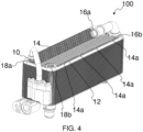
- FIG. 4 illustrates an isometric view of a heat exchanger, particularly, a water-cooled condenser 100 configured by assembling a plurality of plates, at least one plate being configured with blocking element 14a.
- the blocking element 14a extends from at least one of the corrugations 14 to the corresponding peripheral rib 12, in order to block the gap between the corrugation 14 and the corresponding peripheral rib 12. Referring to FIG.
- each plate 10, 20 includes a peripheral rib 12, 22, a plurality of corrugations 14, 24, a first set of inlet and outlet holes 16a, 26a and 16b, 26b, a second set of inlet and outlet holes 18a, 28a and 18b, 28b.
- the peripheral rib 12, 22 defines the boundary of the plate 10, 20.
- the corrugations 14, 24 formed on the plate 10, 20 in conjunction with corrugations 14, 24 on adjacent overlapping plate 10, 20 define first fluid flow passages "A” and second fluid flow passages "B" on opposite sides of the plate 10, 20, the second fluid flow passages "B” being adjacent to the first fluid flow passages "A".
- the first inlet and outlet is defined by the first set of inlet and outlet holes 16a, 26a and 16b, 26b formed on the corresponding plate 10, 20.
- the first inlet and outlet is in fluid communication with the first fluid flow passages "A” for ingress and egress of first fluid with respect to the first fluid passages "A”.
- the second inlet and outlet is defined by the second set of inlet and outlet holes 18a, 28a and 18b, 28b.
- the second inlet and outlet is in fluid communication with the second fluid flow passages "B” for ingress and egress of second fluid with respect to the second fluid passages "B"
- the first inlet and outlet is defined by aligning a first set of inlet and outlet holes 16a, 26a and 16b, 26b formed on the respective adjacent plates 10 and 20. More specifically, the first set of inlet and outlet holes 16a and 16b formed on the first set of plates 10 are arranged alternatively with respect to the first set of inlet and outlet holes 26a and 26b formed on the second set of plates 20 to define the first inlet and outlet.
- the second inlet and outlet is defined by aligning the second set of inlet and outlet holes 18a, 28a and 18b, 28b formed on the respective adjacent plates 10 and 20.
- the second set of inlet and outlet holes 18a and 18b formed on the first set of plates 10 are arranged alternatively with respect to the second set of inlet and outlet holes 28a and 28b formed on the second set of plates 20 to define the first inlet and outlet.
Landscapes
- Engineering & Computer Science (AREA)
- Physics & Mathematics (AREA)
- Thermal Sciences (AREA)
- Mechanical Engineering (AREA)
- General Engineering & Computer Science (AREA)
- Heat-Exchange Devices With Radiators And Conduit Assemblies (AREA)
Abstract
Description
- The present invention relates to a plate. In particular, this invention relates to a plate for a heat exchanger.
- A heat exchanger 1, for example, a water cooled condenser, generally includes a plurality of heat exchange plates, particularly, a first set of
plates 2 simply referred to asfirst plates 2 and second set ofplates 3, simply referred to assecond plates 3.FIG. 1a of the accompanying drawings, depicts theplate 2 of the first set of plates. Theplates corrugations peripheral ribs 2b, 3b circumscribing thecorrugations plates plates 2 and the second set ofplates 3 with correspondingcorrugations FIG. 1b to form a plurality of adjacent first and second fluid flow passages "a" and "b" respectively. The first and second heat exchange fluid, flows through the first and second fluid flow passages "a" and "b" respectively to cause heat exchange there-between. The first fluid flow passages "a" are in fluid communication with a first set of inlet and outlet defined byapertures plates 2 for ingress and egress of the first fluid with respect to the heat exchanger 1. More specifically, the first fluid enters at least one of the first fluid flow passages "a" through the first inlet and after flowing through at least one of the first fluid flow passages "a" and after undergoing heat exchange with second heat exchange fluid flowing through second fluid flow passages "b", the first fluid egresses at least one of the first fluid flow passages "a" through the first outlet. Similarly, the second fluid flow passages "b" are in fluid communication with a second set of inlet and outlet defined by apertures 3c and 3d formed on thesecond plates 3 for ingress and egress of the second fluid with respect to the heat exchanger 1. More specifically, the second fluid enters at least one of the second fluid flow passages "b" through the second inlet and after flowing through at least one of the second fluid flow passages "b" and after undergoing heat exchange with the first fluid, the second fluid egresses at least one of the second fluid flow passages "b" through the second outlet. Thefirst plate 2 is configured withapertures adjacent plates 3 to define the second inlet and outlet. In case the heat exchanger 1 is a water cooled, a refrigerant flows through the first fluid flow passages "a" and the coolant, particularly water flows through the second fluid flow passages "b". - Further referring to the
FIG. 1b , each of theplates corrugations corrugations 2a formed on theplate 2 are arranged with respect to thecorrugations 3a formed on theadjacent plate 3 to define the heat exchange passages "a" and "b" by theadjacent plates corrugations adjacent plates adjacent plates corrugations plates corrugations plates corrugation peripheral rib 2b, 3b. Accordingly, theplates corrugations peripheral rib 2b, 3b. More specifically, the escape routes cause the heat exchange fluids to bypass the first and second heat exchange passages "a" and "b" defined between theplates corrugations 2a and 3b formed on theplates plates - Accordingly, there is a need for a plate for a heat exchanger that improves the efficiency and performance of the heat exchanger by preventing the heat exchange fluids from bypassing the first and the second fluid flow passages and escaping through the outlets, without undergoing heat exchange. Furthermore, there is a need for a plate that directs first and second heat exchange fluids to and uniform distribution of the heat exchange fluid to the respective fluid flow passages. Further, there is a need for a heat exchange plate that is simple in construction and that improves efficiency and performance of the heat exchanger.
- An object of the present invention is to provide a plate for a heat exchanger that obviates the problems arising due to heat exchange fluids bypassing the first and the second fluid flow passages and escaping though the outlets without undergoing heat exchange.
- Another object of the present invention is to provide a plate for heat exchanger that is simple in construction.
- Still another object of the present invention is to provide a plate for a heat exchanger that improves heat exchange between the heat exchange fluids by enhancing contact area and contact time between the heat exchanging fluids, thereby improving efficiency and performance of the heat exchanger.
- In the present description, some elements or parameters may be indexed, such as a first element and a second element. In this case, unless stated otherwise, this indexation is only meant to differentiate and name elements which are similar but not identical. No idea of priority should be inferred from such indexation, as these terms may be switched without betraying the invention. Additionally, this indexation does not imply any order in mounting or use of the elements of the invention.
- A plate for a heat exchanger is disclosed in accordance with an embodiment of the present invention. The plate includes a peripheral rib, a plurality of corrugations, a first set of inlet and outlet holes and a second set of inlet and outlet holes. The peripheral rib defines the boundary of the plate. The plurality of corrugations formed within the peripheral rib of the corresponding plate. The corrugations in conjunction with corrugations formed on adjacent overlapping plates define first fluid flow passages "A" and second fluid flow passages "B" on opposite sides of the plate, the second fluid flow passages "B" being adjacent to the first fluid flow passages "A". The first set of inlet and outlet holes define a first inlet and outlet that are in fluid communication with the first fluid passages "A" and the second set of inlet and outlet holes defining a second inlet and outlet are in fluid communication with the second fluid passages "B". At least one of the plates includes at least one blocking element formed thereon to at least partially block gap between at least one corrugation and the corresponding peripheral rib.
- The corrugations formed on the plates are angular corrugations that are diverging from an axis "C" of the plate towards the corresponding peripheral rib.
- In accordance with an embodiment of the present invention, the blocking element is extending from at least one of peripheral rib and extreme end of at least one corrugation.
- Generally, the blocking element is extending from peripheral rib till extreme end of at least one corrugation.
- Alternatively, the blocking element is extending from extreme end of at least one corrugation till the corresponding peripheral rib.
- In accordance with still another embodiment of the present invention, the blocking element is extending from at least one of the adjacent overlapping plates and at least partially blocks gap between extreme end of at least one corrugation and the corresponding peripheral rib.
- More specifically, the blocking element is inclined towards the corrugations and direct fluid to the fluid flow passages defined by the corrugations.
- A heat exchanger is disclosed in accordance with an embodiment of the present invention. The heat exchanger includes a plurality of plates, a first inlet and outlet, a second inlet and outlet. The plates are stacked overlapping with respect to each other. Each of the plates includes a peripheral rib, a plurality of corrugations, a first set of inlet and outlet holes and a second set of inlet and outlet holes. The peripheral rib defines boundary of the plate. The plurality of corrugations formed on the plate in conjunction with corrugations on adjacent overlapping plate define first fluid flow passages "A" and second fluid flow passages "B" on opposite sides of the plate, the second fluid flow passages being adjacent to the first fluid flow passages. The first inlet and outlet are defined by the first set of inlet and outlet holes. The first inlet and outlet are in fluid communication with the first fluid flow passages for ingress and egress of first fluid with respect to the first fluid passages "A". The second inlet and outlet is defined by the second set of inlet and outlet holes. The second inlet and outlet being in fluid communication with the second fluid flow passages for ingress and egress of second fluid with respect to the second fluid passages "B". At least one of the plates includes at least one blocking element formed thereon to at least partially block gap between extreme end of at least one corrugation and the corresponding peripheral rib.
- Generally, the first set of inlet and outlet is defined by aligning a first set of inlet and outlet holes formed on the respective adjacent plates.
- Similarly, the second set of inlet and outlet is defined by aligning a second set of inlet and outlet holes formed on the respective adjacent plates.
- Other characteristics, details and advantages of the invention can be inferred from the description of the invention hereunder. A more complete appreciation of the invention and many of the attendant advantages thereof will be readily obtained as the same becomes better understood by reference to the following detailed description when considered in connection with the accompanying figures, wherein:
-
FIG. 1a illustrates a conventional plate of a first set of plates of a conventional heat exchanger; -
FIG. 1b illustrates a schematic representation of the first set of plates and a second set of plates with corrugations formed thereon stacked with respect to each other to define first and second fluid flow passages of the heat exchanger ofFIG. 1a ; -
FIG. 2 illustrates a schematic representation of a plate for a heat exchanger in accordance with an embodiment of the present invention, also is illustrated an enlarged view depicting at least one corrugation formed with a blocking element; -
FIG. 3 illustrates a schematic representation of the first set of plates and a second set of plates in accordance with an embodiment of the present invention stacked with respect to each other to define first and second fluid flow passages, wherein gap between corrugations and corresponding peripheral rib formed on the plate is blocked by blocking elements; and -
FIG. 4 illustrates an isometric view of a heat exchanger, particularly, a water-cooled condenser configured by assembling a plurality of plates, at least one plate being the plate ofFIG. 2 , the water-cooled condenser is illustrated without a top cover and a top plate to depict the plate ofFIG. 2 . - It must be noted that the figures disclose the invention in a detailed enough way to be implemented, said figures helping to better define the invention if needs be. The invention should however not be limited to the embodiment disclosed in the description.
- Although, the present invention is explained in the forthcoming description and accompanying drawings with example of a water cooled condenser used in vehicular environment, however, the present invention is not limited to any particular heat exchanger and is applicable to any other heat exchangers such as chillers, oil coolers used in vehicular or non-vehicular environments, wherein the efficiency and performance of the heat exchanger is required to be improved by improving the heat exchange between the heat exchange fluids and preventing the escape of the heat exchange fluid through the gap between extreme ends of the corrugations and the peripheral rib without undergoing heat exchange.
-
FIG. 1a of the accompanying drawings, depicts aplate 2 of plurality of plates of a heat exchanger 1, for example, a water-cooled condenser 1. Referring toFIG. 1b ,plates plates corrugations respective plates plates peripheral rib 2b and 3b defines boundary of theplates peripheral rib 2b and 3b circumscribes thecorrugations plates corrugations peripheral ribs 2b and 3b are formed by the stamping operation. Due to limitation of the stamping process, thecorrugations peripheral rib 2b and 3b formed on the correspondingplates plates peripheral rib 2b, 3b and the corrugated section of theplate plates plates plates corrugations adjacent plates plates 2 instead of being distributed to the first fluid flow passages "a" for heat exchange with the second fluid flowing through second fluid flow passages "b". Similarly, the second fluid escapes through the bypass passage formed by the peripheral channel "c" inherently formed on theadjacent plates 3 instead of being distributed to the second fluid flow passages "b" for heat exchange with the first fluid flowing through first fluid flow passages "a", thereby hampering heat exchange between the first and the second fluid and reducing the efficiency and performance of the heat exchanger 1. - To overcome the above problem, the present invention envisages a
plate FIG. 2 . Theplate heat exchanger 100, for example, a water cooledcondenser 100, wherein each plate is formed with at least one blockingelement heat exchanger 100 includes a first set ofplates 10 and a second set ofplates 20 that are stacked alternative to each other as depicted inFIG. 3 . Theplate heat exchanger 100 includes a correspondingperipheral rib corrugations 14, 24 formed within theperipheral rib corresponding plate outlet holes outlet holes element element corrugation 14, 24 and the correspondingperipheral rib corresponding plate element corrugation 14, 24 and the correspondingperipheral rib corresponding plate element plates heat exchanger 100 through the gap between thecorrugation 14, 24 and the correspondingperipheral rib plates element plate element heat exchanger 100 is improved. - The
peripheral rib corresponding plate peripheral rib corresponding plate peripheral rib peripheral rib - The plurality of
corrugations 14, 24 are formed on thecorresponding plate peripheral rib corresponding plate plate corrugations 14, 24 formed on theplate corrugations 14, 24 formed on adjacent overlappingplates plate corrugations 14 formed on theplate 10 in conjunction with the corrugations 24 formed on theplate 20 - The
corrugations 14, 24 are also formed along with theperipheral rib corrugations 14, 24 are angular corrugations that are diverging from an axis "C" of theplate peripheral rib corrugations 14, 24 are angular corrugations that are converging at an axis "C" of theplate peripheral rib corrugations 14, 24 are of non-uniform length. Among the corrugations, few corrugations are comparative shorter than other corrugation. Thecorrugations 14, 24 can be arranged along any other profile on theplates peripheral rib plate corrugations 14, 24 formed on adjacent overlappingplates - Each
plate outlet holes outlet holes outlet holes plates 10 in conjunction with holes 26a, 26b formed on the adjacent second set ofplates 20 define the first inlet and outlet that are in fluid communication with the first fluid flow passage "A" for ingress and egress of the first heat exchange fluid in and out from the first fluid flow passage "A". The first set of inlet andoutlet holes plates 10 are aligned to the inlet and outlet holes 26a and 26b formed on the adjacent second set ofplates 20 to define the first inlet and outlet. The inlet and outlet can be formed on the same side or on opposite sides of the heat exchanger. The position of the first set of inlet and outlet holes and the second set of inlet and outlet holes formed on the first and the second plate changes based on whether the inlet and outlet are formed on the same side or on opposite sides of the heat exchanger. - Similarly, the second set of inlet and outlet holes 28a and 28b formed on the second set of
plates 20 in conjunction withholes plates 10 define the second inlet and outlet that are in fluid communication with the second fluid flow passage "B" for ingress and egress of the first heat exchange fluid in and out from the second fluid flow passage "B". Theholes plates 10 are aligned to the second set of inlet and outlet holes 28a and 28b formed on the adjacent second set ofplates 20 to define the second inlet and outlet. - At least one plate of the first and second set of
plates element element corrugation 14, 24 and the correspondingperipheral rib corresponding plate element corrugation 14, 24 and the correspondingperipheral rib corresponding plate peripheral rib corrugation 14, 24 formed on thecorresponding plate peripheral rib element peripheral rib corrugation 14, 24 but also guides the first and the second heat exchange fluid to the respect first and second fluid flow passages "A" and "B" respectively. Accordingly, the plates of the present invention configured with the blocking element improves heat exchange between the heat exchange fluids flowing on opposite sides thereof by enhancing contact area and contact time between the heat exchanging fluids, thereby improving efficiency and performance of the heat exchanger. - In accordance with an embodiment of the present invention, the blocking
element peripheral rib corrugation 14, 24 formed on thecorresponding plate element peripheral rib corrugation 14, 24 formed on thecorresponding plate element corrugation 14, 24 till the correspondingperipheral rib FIG. 2 , the blockingelement 14a extends from extreme end of at least onecorrugation 14 till the correspondingperipheral rib 12 formed on theplate 10. Also is depicted enlarged view depicting at least onecorrugation 14 formed with the blockingelement 14a. The blockingelement corrugations 14, 24 configured with the blockingelement element 14a extends from extreme end of at least onecorrugation 14 towards theperipheral rib 12 formed on theplate 10 and another portion of the blockingelement 12a extends from theperipheral rib 12 towards extreme end of at least onecorrugation 14. The first portion and the second portion of the blockingelement corrugations 14, 24 and theperipheral rib peripheral rib plates element adjacent plates adjacent plate corrugation 14, 24 and the correspondingperipheral rib element 10a extends from theplate 10 of the first set ofplates 10 towards theplate 20 of the second set ofplates 20 or from thecorrugate plate 20 to theplate 10 to at least partially block inherently formed gap between theperipheral rib 12 and extreme end of at least onecorrugation 14 formed on theplate 10 to direct first heat exchange fluid towards the first fluid flow passages "A", thereby uniformly distributing the first heat exchange fluid in the first flow passages "A". Similarly in another example, the blockingelement 20a can extend from theplate 20 of the second set ofplates 20 towards theplate 10 of the first set of plates to at least partially block inherently formed gap between theperipheral rib 12 and extreme end of at least onecorrugation 14 formed on theplate 10 to direct first heat exchange fluid towards the first fluid flow passages "A". Similarly, the blocking element can be partially formed on theplate 10 and partially formed on theplate 20, more specifically, a portion of the blocking element extends from theplate 10 towards theplate 20 and a remaining portion of the blocking element extends from theplate 20 towards theplate 10 to at least partially block inherently formed gap between theperipheral rib 12 and extreme end of at least onecorrugation 14 formed on theplate 10 to direct first heat exchange fluid towards the first fluid flow passages "A". In another embodiment, the blockingelement corrugations 14, 24 formed on theplate corrugations 14, 24. However, the present invention is not limited to any particular configuration, shape, size, placement of the blocking element as far as the blocking element is capable of at least partially blocking the gap between the at least onecorrugation 14, 24 and the correspondingperipheral rib corresponding plate corrugation 14, 24 andperipheral rib - A
heat exchanger 100 is disclosed in accordance with an embodiment of the present invention. Theheat exchanger 100 includes a plurality ofplates plates 10 and a second set ofplates 20, a first inlet and outlet and a second inlet and outlet.FIG. 4 illustrates an isometric view of a heat exchanger, particularly, a water-cooledcondenser 100 configured by assembling a plurality of plates, at least one plate being configured with blockingelement 14a. The blockingelement 14a extends from at least one of thecorrugations 14 to the correspondingperipheral rib 12, in order to block the gap between thecorrugation 14 and the correspondingperipheral rib 12. Referring toFIG. 4 , the water-cooledcondenser 100 is illustrated without a top cover and the top plate to depict theplate 10. The first set ofplates 10 and the second set ofplates 20 are stacked with respect to each other in an aligned and overlapping manner. Eachplate peripheral rib corrugations 14, 24, a first set of inlet andoutlet holes outlet holes peripheral rib plate corrugations 14, 24 formed on theplate corrugations 14, 24 on adjacent overlappingplate plate outlet holes corresponding plate outlet holes - The first inlet and outlet is defined by aligning a first set of inlet and
outlet holes adjacent plates outlet holes plates 10 are arranged alternatively with respect to the first set of inlet and outlet holes 26a and 26b formed on the second set ofplates 20 to define the first inlet and outlet. The second inlet and outlet is defined by aligning the second set of inlet andoutlet holes adjacent plates outlet holes plates 10 are arranged alternatively with respect to the second set of inlet and outlet holes 28a and 28b formed on the second set ofplates 20 to define the first inlet and outlet. - In any case, the invention cannot and should not be limited to the embodiments specifically described in this document, as other embodiments might exist. The invention shall spread to any equivalent means and any technically operating combination of means.
Claims (10)
- A plate (10, 20) for a heat exchanger (100), the plate (10, 20) comprising:∘ a peripheral rib (12, 22) defining boundary of the plate (10, 20); and∘ a plurality of corrugations (14, 24) formed within the peripheral rib (12, 22) of the corresponding plate (10, 20), the corrugations (14, 24) formed on the plate (10, 20) in conjunction with corrugations (14, 24) formed on adjacent overlapping plates (10, 20) define first fluid flow passages "A" and second fluid flow passages "B" on opposite sides of the plate (10, 20), the second fluid flow passages "B" being adjacent to the first fluid flow passages "A",∘ a first set of inlet and outlet holes (16a, 26a) and (16b, 26b) defining a first inlet and outlet that are in fluid communication with the first fluid passages "A" and a second set of inlet and outlet holes (18a, 28a) and (18b, 28b) defining a second inlet and outlet that are in fluid communication with the second fluid passages "B",characterized in that at least one of the plates (10) and (20) comprises at least one blocking element (12a, 14a, 10a, 20a, 22a, 24a) formed thereon and adapted to at least partially block gap between at least one corrugation (14, 24) and the corresponding peripheral rib (12, 22).
- The plate (10, 20) as claimed in the previous claim, wherein the corrugations (14, 24) are angular corrugations that are diverging from an axis "C" of the plate (10, 20) towards the corresponding peripheral rib (12, 22).
- The plate (10, 20) as claimed in any of the preceding claims, wherein the blocking element (12a, 22a) is extending from at least one of peripheral rib (12, 22) and extreme end of at least one corrugation (14, 24).
- The plate (10, 20) as claimed in any of the preceding claims, wherein the blocking element (12a, 22a) is extending from peripheral rib (12, 22) till extreme end of at least one corrugation (14, 24).
- The plate (10, 20) as claimed in any of the preceding claims, wherein the blocking element (14a, 24a) is extending from extreme end of at least one corrugation (14, 24) till the corresponding peripheral rib (12, 22).
- The plate (10, 20) as claimed in any of the preceding claims, wherein the blocking element (10a, 20a) is extending from at least one of the adjacent plates (10, 20) and adapted to at least partially block gap between extreme end of at least one corrugation (14, 24) and the corresponding peripheral rib (12, 22) formed on one of the adjacent plates (10) and (20).
- The plate (10, 20) as claimed in any of the preceding claims, wherein the blocking element (12a, 14a, 10a, 20a, 22a, 24a) is inclined towards the corrugations (14, 24) and direct fluid to the fluid flow passages defined by the corrugations (14, 24).
- A heat exchanger (100) comprising:• a plurality of plates (10) and (20) stacked overlapping with respect to each other, each plate (10, 20) comprising: ;∘ a peripheral rib (12, 22) defining boundary of the plate (10, 20); and∘ a plurality of corrugations (14, 24) formed thereon in conjunction with corrugations (14, 24) on adjacent overlapping plate (10, 20) define first fluid flow passages "A" and second fluid flow passages "B" on opposite sides of the plate (10, 20), the second fluid flow passages "B" being adjacent to the first fluid flow passages "A";∘ a first set of inlet and outlet holes (16a, 26a) and (16b, 26b) and a second set of inlet and outlet holes (18a, 28a) and (18b, 28b),• a first inlet and outlet defined by the first set of inlet and outlet holes (16a, 26a) and (16b, 26b), the first inlet and outlet being in fluid communication with the first fluid flow passages for ingress and egress of first fluid with respect to the first fluid passages "A";• a second inlet and outlet defined by the second set of inlet and outlet holes (18a, 28a) and (18b, 28b), the second inlet and outlet being in fluid communication with the second fluid flow passages for ingress and egress of second fluid with respect to the second fluid passages "B",characterized in that at least one of the plates (10) and (20) comprises at least one blocking element (12a, 14a, 10a, 20a, 22a, 24a) formed thereon and adapted to at least partially block gap between extreme end of at least one corrugation (14, 24) and the corresponding peripheral rib (12, 22).
- The heat exchanger (100) as claimed in the previous claim, wherein the first inlet and outlet is defined by aligning a first set of inlet and outlet holes (16a, 26a) and (16b, 26b) formed on the respective adjacent plates (10) and (20).
- The heat exchanger (100) as claimed in any of the preceding claims, the second inlet and outlet is defined by aligning the second set of inlet and outlet holes (18a, 28a) and (18b, 28b) formed on the respective adjacent plates (10) and (20).
Priority Applications (4)
| Application Number | Priority Date | Filing Date | Title |
|---|---|---|---|
| EP21202173.7A EP4166880A1 (en) | 2021-10-12 | 2021-10-12 | A plate for a heat exachanger |
| CN202280068366.5A CN118103660A (en) | 2021-10-12 | 2022-10-12 | Plates for heat exchangers |
| PCT/EP2022/078442 WO2023062100A1 (en) | 2021-10-12 | 2022-10-12 | A plate for a heat exchanger |
| US18/695,359 US20240393064A1 (en) | 2021-10-12 | 2022-10-12 | A plate for a heat exchanger |
Applications Claiming Priority (1)
| Application Number | Priority Date | Filing Date | Title |
|---|---|---|---|
| EP21202173.7A EP4166880A1 (en) | 2021-10-12 | 2021-10-12 | A plate for a heat exachanger |
Publications (1)
| Publication Number | Publication Date |
|---|---|
| EP4166880A1 true EP4166880A1 (en) | 2023-04-19 |
Family
ID=78087300
Family Applications (1)
| Application Number | Title | Priority Date | Filing Date |
|---|---|---|---|
| EP21202173.7A Pending EP4166880A1 (en) | 2021-10-12 | 2021-10-12 | A plate for a heat exachanger |
Country Status (4)
| Country | Link |
|---|---|
| US (1) | US20240393064A1 (en) |
| EP (1) | EP4166880A1 (en) |
| CN (1) | CN118103660A (en) |
| WO (1) | WO2023062100A1 (en) |
Citations (5)
| Publication number | Priority date | Publication date | Assignee | Title |
|---|---|---|---|---|
| JP2010054187A (en) * | 2008-08-01 | 2010-03-11 | Toshihiro Yamamoto | Plate heat exchanger |
| US8061416B2 (en) * | 2003-08-01 | 2011-11-22 | Behr Gmbh & Co. Kg | Heat exchanger and method for the production thereof |
| US20120227438A1 (en) * | 2009-11-19 | 2012-09-13 | Daisuke Ito | Plate heat exchanger and heat pump apparatus |
| US20140060789A1 (en) * | 2008-10-03 | 2014-03-06 | Modine Manufacturing Company | Heat exchanger and method of operating the same |
| US10371454B2 (en) * | 2013-10-14 | 2019-08-06 | Alfa Laval Corporate Ab | Plate for heat exchanger and heat exchanger |
Family Cites Families (7)
| Publication number | Priority date | Publication date | Assignee | Title |
|---|---|---|---|---|
| DE3622316C1 (en) * | 1986-07-03 | 1988-01-28 | Schmidt W Gmbh Co Kg | Plate heat exchanger |
| FR2931542A1 (en) * | 2008-05-22 | 2009-11-27 | Valeo Systemes Thermiques | HEAT EXCHANGER WITH PLATES, IN PARTICULAR FOR MOTOR VEHICLES |
| SE533359C2 (en) * | 2008-12-16 | 2010-09-07 | Alfa Laval Corp Ab | Plate and gasket for a plate heat exchanger |
| JP5661119B2 (en) * | 2010-11-12 | 2015-01-28 | 三菱電機株式会社 | Plate heat exchanger and heat pump device |
| US9163882B2 (en) * | 2011-04-25 | 2015-10-20 | Itt Manufacturing Enterprises, Inc. | Plate heat exchanger with channels for ‘leaking fluid’ |
| KR101401987B1 (en) * | 2011-11-01 | 2014-05-30 | 한라비스테온공조 주식회사 | Plate Type Heat Exchanger |
| DE102013220313B4 (en) * | 2013-10-08 | 2023-02-09 | Mahle International Gmbh | Stacked disc heat exchanger |
-
2021
- 2021-10-12 EP EP21202173.7A patent/EP4166880A1/en active Pending
-
2022
- 2022-10-12 WO PCT/EP2022/078442 patent/WO2023062100A1/en not_active Ceased
- 2022-10-12 US US18/695,359 patent/US20240393064A1/en active Pending
- 2022-10-12 CN CN202280068366.5A patent/CN118103660A/en active Pending
Patent Citations (5)
| Publication number | Priority date | Publication date | Assignee | Title |
|---|---|---|---|---|
| US8061416B2 (en) * | 2003-08-01 | 2011-11-22 | Behr Gmbh & Co. Kg | Heat exchanger and method for the production thereof |
| JP2010054187A (en) * | 2008-08-01 | 2010-03-11 | Toshihiro Yamamoto | Plate heat exchanger |
| US20140060789A1 (en) * | 2008-10-03 | 2014-03-06 | Modine Manufacturing Company | Heat exchanger and method of operating the same |
| US20120227438A1 (en) * | 2009-11-19 | 2012-09-13 | Daisuke Ito | Plate heat exchanger and heat pump apparatus |
| US10371454B2 (en) * | 2013-10-14 | 2019-08-06 | Alfa Laval Corporate Ab | Plate for heat exchanger and heat exchanger |
Also Published As
| Publication number | Publication date |
|---|---|
| WO2023062100A1 (en) | 2023-04-20 |
| US20240393064A1 (en) | 2024-11-28 |
| CN118103660A (en) | 2024-05-28 |
Similar Documents
| Publication | Publication Date | Title |
|---|---|---|
| CN216790965U (en) | Heat exchanger and heat transfer surface | |
| CN114598051B (en) | Motor for vehicle and vehicle | |
| US6250380B1 (en) | Heat exchanger, especially for gases and fluids | |
| KR101124874B1 (en) | Plate heat exchanger | |
| CN110411248B (en) | Stacked plate heat exchanger | |
| EP2420791A2 (en) | Plate heat exchanger | |
| JP5882179B2 (en) | Internal heat exchanger with external manifold | |
| EP3484254B1 (en) | Laminated heat sink core | |
| EP3505857B1 (en) | Plate heat exchanger | |
| JP2002164491A (en) | Stack cooler | |
| KR100687637B1 (en) | heat transmitter | |
| JP6717326B2 (en) | Heat exchanger | |
| EP3517873A1 (en) | Heat exchanger and method of cooling a flow of heated air | |
| US20240393064A1 (en) | A plate for a heat exchanger | |
| KR102069804B1 (en) | Heat exchanger and heat exchanging device comprising the same | |
| JP7393527B2 (en) | Heat exchanger | |
| CN111765786A (en) | Heat Exchangers and Heat Exchanger Assemblies | |
| KR20190033929A (en) | Oil Cooler | |
| JP7683025B2 (en) | Cooler including two substantially parallel flow chambers and three substantially parallel plates | |
| JP2008106969A (en) | Plate type heat exchanger | |
| EP4023993A1 (en) | A heat exchanger | |
| KR100903091B1 (en) | Oil cooler | |
| JP7696756B2 (en) | Surface contact heat exchanger | |
| KR100819010B1 (en) | heat transmitter | |
| EP4023995A1 (en) | Heat exchanger |
Legal Events
| Date | Code | Title | Description |
|---|---|---|---|
| PUAI | Public reference made under article 153(3) epc to a published international application that has entered the european phase |
Free format text: ORIGINAL CODE: 0009012 |
|
| STAA | Information on the status of an ep patent application or granted ep patent |
Free format text: STATUS: THE APPLICATION HAS BEEN PUBLISHED |
|
| AK | Designated contracting states |
Kind code of ref document: A1 Designated state(s): AL AT BE BG CH CY CZ DE DK EE ES FI FR GB GR HR HU IE IS IT LI LT LU LV MC MK MT NL NO PL PT RO RS SE SI SK SM TR |
|
| STAA | Information on the status of an ep patent application or granted ep patent |
Free format text: STATUS: REQUEST FOR EXAMINATION WAS MADE |
|
| 17P | Request for examination filed |
Effective date: 20231019 |
|
| RBV | Designated contracting states (corrected) |
Designated state(s): AL AT BE BG CH CY CZ DE DK EE ES FI FR GB GR HR HU IE IS IT LI LT LU LV MC MK MT NL NO PL PT RO RS SE SI SK SM TR |
|
| STAA | Information on the status of an ep patent application or granted ep patent |
Free format text: STATUS: EXAMINATION IS IN PROGRESS |
|
| 17Q | First examination report despatched |
Effective date: 20250409 |