EP4166722A1 - Method for disassembling offshore structure - Google Patents
Method for disassembling offshore structure Download PDFInfo
- Publication number
- EP4166722A1 EP4166722A1 EP22199980.8A EP22199980A EP4166722A1 EP 4166722 A1 EP4166722 A1 EP 4166722A1 EP 22199980 A EP22199980 A EP 22199980A EP 4166722 A1 EP4166722 A1 EP 4166722A1
- Authority
- EP
- European Patent Office
- Prior art keywords
- tower
- sheet shape
- disassembling
- offshore structure
- offshore
- Prior art date
- Legal status (The legal status is an assumption and is not a legal conclusion. Google has not performed a legal analysis and makes no representation as to the accuracy of the status listed.)
- Granted
Links
Images











Classifications
-
- E—FIXED CONSTRUCTIONS
- E02—HYDRAULIC ENGINEERING; FOUNDATIONS; SOIL SHIFTING
- E02B—HYDRAULIC ENGINEERING
- E02B17/00—Artificial islands mounted on piles or like supports, e.g. platforms on raisable legs or offshore constructions; Construction methods therefor
-
- B—PERFORMING OPERATIONS; TRANSPORTING
- B63—SHIPS OR OTHER WATERBORNE VESSELS; RELATED EQUIPMENT
- B63B—SHIPS OR OTHER WATERBORNE VESSELS; EQUIPMENT FOR SHIPPING
- B63B35/00—Vessels or similar floating structures specially adapted for specific purposes and not otherwise provided for
- B63B35/003—Vessels or similar floating structures specially adapted for specific purposes and not otherwise provided for for transporting very large loads, e.g. offshore structure modules
-
- E—FIXED CONSTRUCTIONS
- E02—HYDRAULIC ENGINEERING; FOUNDATIONS; SOIL SHIFTING
- E02B—HYDRAULIC ENGINEERING
- E02B17/00—Artificial islands mounted on piles or like supports, e.g. platforms on raisable legs or offshore constructions; Construction methods therefor
- E02B2017/0052—Removal or dismantling of offshore structures from their offshore location
-
- Y—GENERAL TAGGING OF NEW TECHNOLOGICAL DEVELOPMENTS; GENERAL TAGGING OF CROSS-SECTIONAL TECHNOLOGIES SPANNING OVER SEVERAL SECTIONS OF THE IPC; TECHNICAL SUBJECTS COVERED BY FORMER USPC CROSS-REFERENCE ART COLLECTIONS [XRACs] AND DIGESTS
- Y02—TECHNOLOGIES OR APPLICATIONS FOR MITIGATION OR ADAPTATION AGAINST CLIMATE CHANGE
- Y02E—REDUCTION OF GREENHOUSE GAS [GHG] EMISSIONS, RELATED TO ENERGY GENERATION, TRANSMISSION OR DISTRIBUTION
- Y02E10/00—Energy generation through renewable energy sources
- Y02E10/70—Wind energy
- Y02E10/72—Wind turbines with rotation axis in wind direction
Definitions
- the present disclosure relates to a method for disassembling an offshore structure provided with a tower of various facilities including an observation facility, a communication facility, an illuminating facility, a mining facility, a power generation facility, and the like (e.g., a meteorological tower, a transmission tower, a lighthouse, or an offshore wind turbine).
- a meteorological tower e.g., a meteorological tower, a transmission tower, a lighthouse, or an offshore wind turbine.
- Patent Document 1 discloses a method for safely demolishing a taut mooring type floating body for mooring a floating structure, in relation to an offshore wind turbine provided with a floating structure.
- water is injected into a water injection part for submergence which is provided for the floating structure to submerge the floating structure, and the mooring cable is cut in a loosened state, thereby ensuring safety.
- Patent Document 2 discloses, as a method for disassembling a wind turbine without building a scaffold, a method of disassembling a tower sequentially from the top, using a crane apparatus disposed inside the tower of the wind turbine.
- the inventors of the present invention have been researching, as a method for disassembling an offshore structure provided with a tower, a method of disassembling an offshore structure by cutting the root part of the tower by an explosive or a laser and then bringing down the body of the offshore structure (the part above the cutting position of the offshore structure) before disassembling, in order to minimize high place works.
- the body of the offshore structure is to be collapsed, the body may sink under the sea where recovery is not possible.
- an object of at least one embodiment of the present disclosure is to provide a method for disassembling an offshore structure whereby it is possible to safely disassemble an offshore structure provided with a tower and recover the body of an offshore structure.
- a method for disassembling an offshore structure includes: a transportation step of transporting a structure having a sheet shape toward a tower of the offshore structure; a setting step of setting the structure having a sheet shape beside the tower; a collapsing step of cutting the tower and collapsing a body of the offshore structure toward the structure having a sheet shape; and a recovery step of recovering the body of the offshore structure.
- an expression of relative or absolute arrangement such as “in a direction”, “along a direction”, “parallel”, “orthogonal”, “centered”, “concentric” and “coaxial” shall not be construed as indicating only the arrangement in a strict literal sense, but also includes a state where the arrangement is relatively displaced by a tolerance, or by an angle or a distance whereby it is possible to achieve the same function.
- an expression of an equal state such as “same” “equal” and “uniform” shall not be construed as indicating only the state in which the feature is strictly equal, but also includes a state in which there is a tolerance or a difference that can still achieve the same function.
- an expression of a shape such as a rectangular shape or a cylindrical shape shall not be construed as only the geometrically strict shape, but also includes a shape with unevenness or chamfered corners within the range in which the same effect can be achieved.
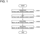
- FIG. 1 is a flowchart schematically showing a method for disassembling a meteorological tower according to an embodiment of the present disclosure.
- the disassembling method illustrated in FIG. 1 includes a transportation step (S101) of transporting a structure having sheet shape toward a tower (column part) of a meteorological tower, a setting step (S102) of setting a structure having a sheet shape beside the tower, a collapsing step (S103) of cutting the tower and collapsing a body of the meteorological tower toward the structure having a sheet shape, and a recovery step (S104) of recovering the body of the meteorological tower.
- a transportation step (S101) of transporting a structure having sheet shape toward a tower (column part) of a meteorological tower includes a setting step (S102) of setting a structure having a sheet shape beside the tower, a collapsing step (S103) of cutting the tower and collapsing a body of the meteorological tower toward the structure having a sheet shape, and a recovery step (S104) of recovering the body of the meteorological tower.
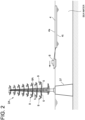
- FIG. 2 is a diagram for describing an example of the transportation step (S101) illustrated in FIG. 1 .
- the meteorological tower 2A includes a tower 8A erected on a foundation 37 fixed to the seabed, and a plurality of branch-shaped protrusions 5 branched and extending from the tower 8A.
- Each of the branch-shaped protrusions 5 is provided with a measurement instrument 9 for observing parameters related to meteorological phenomenon (e.g., wind direction, wind velocity, temperature, humidity, rainfall, or the like).
- the structure 4 having a sheet shape is transported by a ship 6 to the position where the meteorological tower 2A is installed.
- the ship 6 may tow and transport the structure 4 having a sheet shape, or, in a case where the structure 4 having a sheet shape is foldable, the structure 4 having a sheet shape may be transported in a folded state, by being towed or loaded on the ship 6.
- the structure 4 having a sheet shape is a membranous structure (sheet) including a first surface 4s (top surface) formed continuously in a flat shape and a second surface 4t (bottom surface) formed continuously in a flat shape at the opposite side to the first surface 4s.
- sheet membranous structure
- the material of the structure 4 having a sheet shape may be a material that floats on the sea water, for instance, polyester, EVA (ethylene-vinyl acetate), polypropylene, or the like.
- the specific gravity of the structure 4 having a sheet shape may be not greater than 1.02, such that the structure 4 having a sheet shape floats on the sea water.
- the specific gravity of the structure 4 having a sheet shape may be such a specific gravity that the structure 4 having a sheet shape does not sink in a state where the body (described below) of the meteorological tower 2A is loaded on the structure 4 having a sheet shape.
- the material of the structure 4 having a sheet shape may be a material that does not float on the sea water, in which case a float (described below) formed of a material that floats on the sea water may be attached to the structure 4 having a sheet shape.
- FIG. 3 is a diagram for describing an example of the setting step (S102) illustrated in FIG. 1 .
- the structure 4 having a sheet shape is set beside the tower 8A.
- the structure 4 having a sheet shape is set in the direction d1 in which the body 2a of the meteorological tower 2A is to be collapsed, with respect to the position of the tower 8A.
- the structure 4 having a sheet shape is floated on the sea surface beside the tower 8.
- the body 2a of the meteorological tower 2A refers to the part of the meteorological tower 2A above the cutting position (described below) of the tower 8A, and includes, for instance, a part of the tower 8 and a part of the plurality of branch-shaped protrusions 5.
- the structure 4 having a sheet shape in a folded state is expanded and set beside the tower 8A in S102.
- "setting the structure 4 having a sheet shape beside the tower 8A” means that, more specifically, setting the structure 4 having a sheet shape on the sea in a certain direction with respect to the tower 8A such that the distance between the tower 8A and the structure 4 having a sheet shape is less than 'h', where 'h' is the height of the tower 8A from the sea surface.
- the structure 4 having a sheet shape may be fixed in a state where tension is applied to the structure 4 having a sheet shape with a plurality of ships 6 (see FIG. 3 ) or a plurality of anchors 20 (see FIG. 4 ) so that the structure 4 having a sheet shape does not move in response to wind, wave, or the like.
- the anchors 20 are provided via anchor cables 18 at the respective four corners of the structure 4 having a sheet shape that is rectangular in a planar view, thereby fixing the structure 4 having a sheet shape in a state where tension is applied to the structure 4 having a sheet shape using the anchors 20.
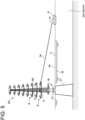
- FIG. 5 is a diagram for describing an example of the collapsing step (S103) illustrated in FIG. 1 .
- the dotted line in FIG. 5 indicates the cutting position P1 for cutting the tower 8A in S103.
- the root part 8r of the tower 8A may be cut by a laser or an explosive, for instance, while at least one ship 6 pulls the tower 8A toward the structure 4 having a sheet shape with a rope 24 or the like.
- the body 2a of the meteorological tower 2A may be collapsed toward the direction d1 between two directions g1, g2 that are different from one another by cutting the tower 8A while pulling the tower 8A in the two different directions g1, g2 via ropes 24 with two ships 6.
- the body 2a of the meteorological tower 2A may be collapsed toward the direction d1 in the middle of the two different directions g1, g2 by cutting the tower 8A while pulling the tower 8A from the two different directions g1, g2 via ropes 24 with two ships 6 at equal forces.
- FIG. 6 the body 2a of the meteorological tower 2A may be collapsed toward the direction d1 between two directions g1, g2 that are different from one another by cutting the tower 8A while pulling the tower 8A in the two different directions g1, g2 via ropes 24 with two ships 6.
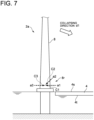
- FIG. 7 is a diagram for describing another example of the collapsing step (S103) illustrated in FIG. 1 .
- the first incision C1, the second incision C2, and the third incision C3 may be formed on the tower 8A with a laser.
- the root part 8r of the tower 8A is irradiated with a laser a1 from the side of the tower 8A closer to the structure 4 having a sheet shape (the first side) so as not to penetrate the tower 8A, and the first incision C1 is formed on the tower 8 (first irradiation step).
- the root part 8r of the tower 8A is irradiated with a laser a2 from the side of the tower 8A closer to the structure 4 having a sheet shape so as not to penetrate the tower 8A at an angle different from that of the first incision C1, and the second incision C2 connecting to the first incision C1 is formed on the tower 8A, whereby a section (fragment) between the first incision C1 and the second incision C2 on the tower 8A is removed from the tower 8 (second irradiation step).
- the root part 8r of the tower 8A is irradiated with a laser a3 from the opposite side (second side) of the tower 8A to the structure 4 having a sheet shape, and the third incision C3 connecting to at least one of the first incision C1 or the second incision C2 is formed (third radiation step), whereby the tower 8A is cut off.
- each of the first incision C1 and the third incision C3 is formed on the root part 8r of the tower 8A along the horizontal direction
- the second incision C2 is formed on the root part 8r of the tower 8A from above toward the bottom diagonally.
- the direction in a case where there is a direction in which the branch-shaped protrusion 5 is not protruding from the tower 8A, the direction may be used as the collapsing direction d1.
- the direction in which the branch-shaped protrusion 5 is not protruding from the tower 8A is facing downward.
- the branch-shaped protrusion 5 extending in the collapsing direction d1 may be cut and removed before cutting the tower 8A. Accordingly, it is possible to suppress breakage of the structure 4 having a sheet shape due to the branch-shaped protrusion 5.
- FIG. 8 is a diagram for describing an example of the recovery step (S104) illustrated in FIG. 1 .
- step S104 the structure 4 having a sheet shape on which the body 2a of the meteorological tower 2A is loaded is transported to the shore, and the body 2a of the meteorological tower 2A is hoisted up to the land and recovered.
- the structure 4 having a sheet shape on which the body 2a of the meteorological tower 2A is loaded is towed by the ship 6 to the shore, and then the body 2a of the meteorological tower 2A is hoisted up to the land using a crane 26.
- the body 2a of the meteorological tower 2A may be dismounted into a plurality of components on the sea such that the weight of each component to be hoisted up by the crane 26 does not exceed the allowable load of the crane 26.
- a heavy crane or the like of a dock of a shipyard may be used to hoist up the body 2a of the meteorological tower 2A, for instance.
- a plurality of floats 28 are attached to an outer edge portion 4h of the structure 4 having a sheet shape.
- the number of the floats 28 may be determined such that the structure 4 having a sheet shape does not sink in a state where the body 2a of the meteorological tower 2A is loaded on the structure 4 having a sheet shape.
- the floats 28 may be omitted.
- the structure 4 having a sheet shape is set beside the tower 8A before cutting the tower 8A, and then the tower 8A is cut and the body 2a of the meteorological tower 2A is collapsed toward the structure 4 having a sheet shape. Accordingly, it is possible to prevent the body 2a from the meteorological tower 2A from sinking under the sea by using the structure 4 having a sheet shape and recovering the body 2a of the meteorological tower 2A.
- the tower 8A is cut off and the body 2a of the meteorological tower 2A is collapsed toward the structure 4 having a sheet shape, it is possible to reduce the amount of high place works compared to a case where the meteorological tower 2A is disassembled in high place works by building up scaffolds around the tower 8A while the tower 8A is still standing, and it is possible to disassemble and recover the meteorological tower 2A safely. Furthermore, by catching the collapsing body 2a of the meteorological tower 2A with the structure 4 having a sheet shape, it is possible to suppress occurrence of wave due to the body 2a of the meteorological tower 2A, and suppress scattering of fragments and dusts of the structure, for instance, from the body 2a of the meteorological tower 2A.
- the structure 4 having a sheet shape is transported in a folded state and expanded to be set beside the tower 8A, it is possible to facilitate the transportation work for the structure 4 having a sheet shape and receive a large-scale offshore structure such as the meteorological tower 2A with the structure 4 having a sheet shape in an expanded state.
- the structure 4 having a sheet shape described in the above described embodiment is a membranous structure including the first surface 4s formed continuously in a flat shape and the second surface 4t formed continuously in a flat shape at the opposite side to the first surface 4s
- the structure 4 having a sheet shape may be a net-shaped structure (net) as illustrated in FIG. 9 .
- net net
- the meteorological tower 2A may be disassembled by the following disassembling method described with reference to FIGs. 10 and 11 .
- the basic flow is the same as the steps S101 to S104 illustrated in FIG. 1 , but the setting step in S102 and the recovery step in S104 are different from those in the above described embodiment.
- the step of transporting the structure 4 having a sheet shape to the installation position of the meteorological tower 2A and the step of cutting and collapsing the tower 8A toward the structure 4 having a sheet shape are the same as those in the embodiment described above with reference to FIG. 1 or the like, and thus not described in detail here.
- the following description will describe the step of setting the structure 4 having a sheet shape and the step of transporting the body of the meteorological tower 2A to the shore using the structure 4 having a sheet shape for recovery.
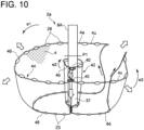
- the structure 4 having a sheet shape is a net, and a plurality of floats 28 are attached at intervals to the upper edge portion 4u of the structure 4 having a sheet shape, and a plurality of weights 23 are attached at intervals to the lower edge portion 4d of the structure 4 having a sheet shape. Furthermore, a rope 46 is passed through the upper edge portion 4u of the structure 4 having a sheet shape, and a rope 48 is passed through the lower edge portion 4d of the structure having a sheet shape.
- the structure 4 having a sheet shape is expanded around the tower 8A (beside the tower 8A) using the ship 6 so as to surround the foundation 37 of the tower 8A with the structure 4 having a sheet shape.
- the ship 6 expands the structure 4 having a sheet shape by passing through the inside of the structure 4 having a sheet shape so as to avoid the tower 8A.
- the ship 6 expands a longitudinal-direction first end side portion 4a of the structure 4 having a sheet shape for about a half round around the tower 8A along the first direction e1, which is one of the clockwise direction or the anticlockwise direction in a planar view.
- the ship 6 expands a longitudinal-direction intermediate portion 4b of the structure 4 having a sheet shape along the second direction e2, which is the other one of the clockwise direction or the anticlockwise direction (opposite direction to the first direction e1) in a planar view, for about a single round along the outer peripheral surface of the tower 8A at the inner peripheral side of the longitudinal-direction first end side portion 4a of the structure 4 having a sheet shape.
- the ship 6 expands a longitudinal-direction second end side portion 4c of the structure 4 having a sheet shape for about a half round along the above first direction e1 at the outer peripheral side of the longitudinal-direction intermediate portion 4b of the structure 4 having a sheet shape. Then, the overlapping portion of the longitudinal-direction intermediate portion 4b at the first side with respect to the tower 8A is fixed (bonded) by using at least one fixture 40 at one location or two locations at different distances from the tower 8A.
- the one or two locations for fixing by the fixture 40 should be preferably at the opposite side to the collapsing direction d1 of the body 2a of the meteorological tower 2A so that the body 2a of the meteorological tower 2A can be readily enveloped with the structure 4 having a sheet shape when the fixing is released afterward.
- the longitudinal-direction intermediate portion 4b of the structure 4 having a sheet shape is disposed so as to surround the tower 8A, and a combination of the longitudinal-direction first end side portion 4a and the longitudinal-direction second end side portion 4c of the structure 4 having a sheet shape is disposed so as to surround the tower 8A at the radially outer side of the longitudinal-direction intermediate portion 4b.
- the longitudinal-direction intermediate portion 4b of the structure 4 having a sheet shape forms a radially inner ring 42 which surrounds the tower 8A
- the combination of the longitudinal-direction first end side portion 4a and the longitudinal-direction second end side portion 4c of the structure 4 having a sheet shape forms a radially outer ring 44 which surrounds the radially inner ring 42.
- the collapsing step it is possible to ensure a large space for accommodating the body 2a of the meteorological tower 2A inside the structure 4 having a sheet shape (between the radially inner ring 42 and the radially outer ring 44) by pulling the structure 4 having a sheet shape with ships toward a plurality of directions away from the tower 8A (four to five directions indicated by empty arrows in FIG. 10 , for instance) to maintain a state where the structure 4 having a sheet shape is expanded, and cutting the tower 8 in the state.
- the fixture 40 In a case where the fixture 40 is provided for a single location, the above side where the large space can be ensured is limited to the opposite side to the fixture 40, and thus it is possible to accommodate the body 2a of the meteorological tower 2A inside the structure 4 having a sheet shape readily by collapsing the body 2a of the meteorological tower 2A toward the opposite side to the fixture 40. In a case where the fixture 40 is provided for two locations, it is possible to position the radially outer ring 44 farther from the radially inner ring 42 and ensure the large space in every direction, thereby increasing the flexibility with regard to the collapsing direction.
- the two fixations by the fixtures 40 are released, and the rope 46 passing through the upper edge portion 4u (the side of the float 28) of the structure 4 having a sheet shape and the rope 48 passing through the lower edge portion 4d (the side of the weight 23) are pulled and drawn by the ship, whereby it is possible to form the structure 4 having a sheet shape into a bag shape and envelope the body 2a of the meteorological tower 2A with the structure 4 having a sheet shape as depicted in FIG. 11 .
- the structure 4 having a sheet shape is set so as to surround the tower 8A, and thus it is possible to accommodate the body 2a of the meteorological tower 2A inside the structure 4 having a sheet shape regardless of the direction in which the tower 8A collapses. Thus, it is possible to prevent the body 2a of the meteorological tower 2A from sinking under the sea more reliably by using the structure 4 having a sheet shape, and recover the body 2a of the wind turbine 2 easily.
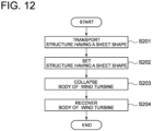
- FIG. 12 is a flowchart schematically showing a method for disassembling an offshore wind turbine according to an embodiment of the present disclosure.
- an offshore wind turbine will be referred to as merely a wind turbine.
- the disassembling method illustrated in FIG. 12 includes a transportation step (S201) of transporting a structure having a sheet shape toward a tower of an offshore wind turbine, a setting step (S202) of setting a structure having a sheet shape beside the tower, a collapsing step (S203) of cutting the tower and collapsing the body of the wind turbine toward the structure having a sheet shape, and a recovery step (S204) of recovering the body of the wind turbine.
- FIG. 13 is a diagram for describing an example of the transportation step (S201) illustrated in FIG. 12 .
- the wind turbine 2B includes a tower 8B, a wind turbine rotor 10, and a nacelle 11.
- the wind turbine rotor 10 includes a plurality of blades 12 and a hub 14 to which the plurality of blades 12 are attached.
- the nacelle 11 supports the hub 14 rotatably.
- the structure 4 having a sheet shape is transported by a ship 6 to the position where the wind turbine 2B is installed.
- the ship 6 may tow and transport the structure 4 having a sheet shape, or, in a case where the structure 4 having a sheet shape is foldable, the structure 4 having a sheet shape may be transported in a folded state, by being towed or loaded on the ship 6.
- the structure 4 having a sheet shape is a membranous structure (sheet) including a first surface 4s (top surface) formed continuously in a flat shape and a second surface 4t (bottom surface) formed continuously in a flat shape at the opposite side to the first surface 4s.
- sheet membranous structure
- the material of the structure 4 having a sheet shape may be a material that floats on the sea water, for instance, polyester, EVA (ethylene-vinyl acetate), polypropylene, or the like.
- the specific gravity of the structure 4 having a sheet shape may be not greater than 1.02, such that the structure 4 having a sheet shape floats on the sea water.
- the structure 4 having a sheet shape is formed of an oil adsorption material (e.g., polypropylene or the like) that adsorbs oil
- an oil adsorption material e.g., polypropylene or the like
- the specific gravity of the structure 4 having a sheet shape may be such a specific gravity that the structure 4 having a sheet shape does not sink in a state where the body (described below) of the wind turbine 2B is loaded on the structure 4 having a sheet shape.
- the material of the structure 4 having a sheet shape may be a material that does not float on the sea water, in which case a float (described below) formed of a material that floats on the sea water may be attached to the structure 4 having a sheet shape.
- the wind turbine 2B is a monopile type wind turbine provided with a foundation 38 fixed to the seabed.
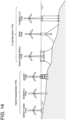
- the method for disassembling a wind turbine 2B according to the present disclosure is applicable to any type of wind turbine, including a fixed-foundation wind turbine such as the gravity base type, the monopile type, and the jacket type, and a floating wind turbine such as the semi-submersible type, the spar type, and the tension leg type, depicted in FIG. 14 .
- FIG. 15 is a diagram for describing an example of the setting step (S202) illustrated in FIG. 12 .
- the structure 4 having a sheet shape is set beside the tower 8B.
- the structure 4 having a sheet shape is set in the direction d1 in which the body 2b of the wind turbine 2B is to be collapsed, with respect to the position of the tower 8B.
- the structure 4 having a sheet shape is floated on the sea surface beside the tower 8B.
- the body 2b of the wind turbine 2B refers to the section above the cutting position (described below) of the tower 8B of the wind turbine 2B, and includes the wind turbine rotor 10, the nacelle 11 (see FIG. 13 ), and a part of the tower 8B.
- the structure 4 having a sheet shape in a folded state is expanded and set beside the tower 8B in S202.
- "setting the structure 4 having a sheet shape beside the tower 8B” means that, more specifically, setting the structure 4 having a sheet shape on the sea in a certain direction with respect to the tower 8B such that the distance between the tower 8B and the structure 4 having a sheet shape is less than 'h', where 'h' is the height of the tower 8B from the sea surface.
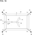
- the structure 4 having a sheet shape may be fixed in a state where tension is applied to the structure 4 having a sheet shape with a plurality of ships 6 (see FIG. 15 ) or a plurality of anchors 20 (see FIG. 16 ) so that the structure 4 having a sheet shape does not move in response to wind, wave, or the like.
- the anchors 20 are provided via anchor cables 18 at the respective four corners of the structure 4 having a sheet shape that is rectangular in a planar view, thereby fixing the structure 4 having a sheet shape in a state where tension is applied to the structure 4 having a sheet shape using the anchors 20.
- an oil fence 22 may be set so as to surround the structure 4 having a sheet shape. Furthermore, while the oil fence 22 is set so as to surround the tower 8B and the structure 4 having a sheet shape in the example illustrated in FIG. 16 , the oil fence 22 may be set so as to surround only the structure 4 having a sheet shape and not the tower 8B.
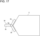
- the shape of the structure 4 having a sheet shape may be a shape conforming to the shape of the floating body 30 of the wind turbine 2B in a planar view.
- the floating body 30 includes three lower hulls 32, and in a planar view, the three lower hulls 32 extend from the position of the tower 8B in respective directions that are different from one another by 120 angular degrees.
- the structure 4 having a sheet shape has a pentagonal shape including two sides that extend along the two lower hulls 32 of the three lower hulls 32 in a planar view, and the two sides make an angle of 120 degrees.
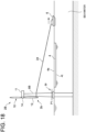
- FIG. 18 is a diagram for describing an example of the collapsing step (S203) illustrated in FIG. 12 .
- the dotted line in FIG. 18 indicates the cutting position P1 for cutting the tower 8B in S203.
- the root part 8r of the tower 8B may be cut by a laser or an explosive, for instance, while at least one ship 6 pulls the tower 8B toward the structure 4 having a sheet shape with the rope 24 or the like.
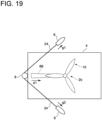
- the body 2b of the wind turbine 2B may be collapsed toward the direction d1 between two directions g1, g2 that are different from one another by cutting the tower 8B while pulling the tower 8B in the two different directions g1, g2 with two ships 6 via the ropes 24.
- the body 2b of the wind turbine 2B may be collapsed toward the direction d1 in the middle of the two different directions g1, g2 by cutting the tower 8B while pulling the tower 8B from the two different directions g1, g2 at equal forces with the two ships 6 via the ropes 24
- FIG. 19 the body 2b of the wind turbine 2B may be collapsed toward the direction d1 between two directions g1, g2 that are different from one another by cutting the tower 8B while pulling the tower 8B in the two different directions g1, g2 with two ships 6 via the ropes 24.
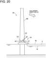
- FIG. 20 is a diagram for describing another example of the collapsing step (S203) illustrated in FIG. 12 .
- the first incision C1, the second incision C2, and the third incision C3 may be formed with a laser.
- the root part 8r of the tower 8B is irradiated with a laser a1 from the side of the tower 8B closer to the structure 4 having a sheet shape (the first side) so as not to penetrate the tower 8B, and the first incision C1 is formed on the tower 8B (first irradiation step).
- the root part 8r of the tower 8B is irradiated with a laser a2 from the side of the tower 8B closer to the structure 4 having a sheet shape so as not to penetrate the tower 8B at an angle different from that of the first incision C1, and the second incision C2 connecting to the first incision C1 is formed on the tower 8B, whereby a section (fragment) between the first incision C1 and the second incision C2 on the tower 8B is removed from the tower 8B (second irradiation step).
- the root part 8r of the tower 8B is irradiated with a laser a3 from the opposite side (second side) of the tower 8B to the structure 4 having a sheet shape, and the third incision C3 connecting to at least one of the first incision C1 or the second incision C2 is formed (third irradiation step), whereby the tower 8B is cut off.
- each of the first incision C1 and the third incision C3 is formed on the root part 8r of the tower 8B along the horizontal direction
- the second incision C2 is formed on the root part 8r of the tower 8B from above toward the bottom diagonally.
- the front side and the back side of the body 2b of the wind turbine 2B refer to the front side (upwind side) and the rear side (downwind side) along the rotational axis of the wind turbine rotor 10, in a case where the wind turbine is a horizontal-axis wind turbine.
- FIG. 21 is a diagram for describing an example of the recovery step (S204) illustrated in FIG. 12 .
- step S204 the structure 4 having a sheet shape on which the body 2b of the wind turbine 2B is loaded is transported to the shore, and the body 2b of the wind turbine 2B is hoisted up to the land and recovered.
- the structure 4 having a sheet shape on which the body 2b of the wind turbine 2B is loaded is towed by the ship 6 to the shore, and then the body 2b of the wind turbine 2B is hoisted up to the land using a crane 26.
- the body 2b of the wind turbine 2B may be dismounted into a plurality of components on the sea such that the weight of each component to be hoisted up by the crane 26 does not exceed the allowable load of the crane 26.
- a heavy crane or the like of a dock of a shipyard may be used to hoist up the body 2b of the wind turbine 2B, for instance.
- a plurality of floats 28 are attached to an outer edge portion 4h of the structure 4 having a sheet shape.
- the number of the floats 28 may be determined such that the structure 4 having a sheet shape does not sink in a state where the body 2b of the wind turbine 2B is loaded on the structure 4 having a sheet shape.
- the floats 28 may be omitted.
- the structure 4 having a sheet shape is set beside the tower 8B before cutting the tower 8B, and then the tower 8B is cut and the body of the wind turbine 2B is collapsed toward the structure 4 having a sheet shape. Accordingly, it is possible to prevent the body 2b of the wind turbine 2B from sinking under the sea by using the structure 4 having a sheet shape and recover the body 2b of the wind turbine 2B.
- the tower 8B is cut off and the body 2b of the wind turbine 2B is collapsed toward the structure 4 having a sheet shape, it is possible to reduce the amount of high place works compared to a case where the wind turbine 2B is disassembled in high place works by building up scaffolds around the tower 8B while the tower 8B is still standing, and it is possible to disassemble and recover the wind turbine 2B safely. Furthermore, by catching the collapsing body 2b of the wind turbine 2B with the structure 4 having a sheet shape, it is possible to suppress occurrence of wave due to the body 2b of the wind turbine 2B, and suppress scattering and leakage of oil, for instance, from the body 2b of the wind turbine 2B.
- the structure having a sheet shape is transported in a folded state and expanded to be set beside the tower, it is possible to facilitate the transportation work for the structure having a sheet shape and receive a large-scale offshore structure such as the wind turbine 2B with the structure 4 having a sheet shape in an expanded state.
- the structure 4 having a sheet shape described in the above described embodiment is a membranous structure including a first surface 4s formed continuously in a flat shape and a second surface 4t formed continuously in a flat shape at the opposite side to the first surface 4s
- the structure 4 having a sheet shape may be a net-shaped structure (net) as illustrated in FIG. 22 .
- net net
- the wind turbine 2B may be disassembled by the following disassembling method described with reference to FIGs. 23 and 24 .
- the basic flow is the same as the steps S201 to S204 illustrated in FIG. 12 , but the setting step in S202 and the recovery step in S204 are different from those in the above described embodiment.
- the step of transporting the structure 4 having a sheet shape to the setting position of the wind turbine 2B and the step of cutting and collapsing the tower 8B toward the structure 4 having a sheet shape are the same as those in the embodiment described above with reference to FIG. 12 or the like, and thus not described in detail here.
- the following description will describe the step of setting the structure 4 having a sheet shape and the step of transporting the body of the wind turbine 2B using the structure 4 having a sheet shape to the shore for recovery.
- the structure 4 having a sheet shape is a net, and a plurality of floats 28 are attached at intervals to the upper edge portion 4u of the structure 4 having a sheet shape, and a plurality of weights 23 are attached at intervals to the lower edge portion 4d of the structure 4 having a sheet shape. Furthermore, a rope 46 is passed through the upper edge portion 4u of the structure 4 having a sheet shape, and a rope 48 is passed through the lower edge portion 4d of the structure 4 having a sheet shape.
- the structure 4 having a sheet shape is expanded around the tower 8B (beside the tower 8B) using the ship 6 so as to surround the foundation 38 of the tower 8B with the structure 4 having a sheet shape.
- the ship 6 expands the structure 4 having a sheet shape by passing through the inside of the structure 4 having a sheet shape so as to avoid the tower 8B.
- the ship 6 expands a longitudinal-direction first end side portion 4a of the structure 4 having a sheet shape for about a half round around the tower 8B along the first direction e1, which is one of the clockwise direction or the anticlockwise direction in a planar view.
- the ship 6 expands a longitudinal-direction intermediate portion 4b of the structure 4 having a sheet shape along the second direction e2, which is the other one of the clockwise direction or the anticlockwise direction (opposite direction to the first direction e1) in a planar view, for about a single round along the outer peripheral surface of the tower 8B at the inner peripheral side of the longitudinal-direction first end side portion 4a of the structure 4 having a sheet shape.
- the ship 6 expands a longitudinal-direction second end side portion 4c of the structure 4 having a sheet shape for about a half round along the above first direction e1 at the outer peripheral side of the longitudinal-direction intermediate portion 4b of the structure 4 having a sheet shape. Then, the overlapping portion of the longitudinal-direction intermediate portion 4b at the first side with respect to the tower 8B is fixed (bonded) by using at least one fixture 40 at one location or two locations at different distances from the tower 8B.
- the one or two locations for fixing by the fixture 40 should be preferably at the opposite side to the collapsing direction d1 of the body 2b of the wind turbine 2B so that the body 2a of the wind turbine 2B can be readily enveloped with the structure 4 having a sheet shape when the fixing is released afterward.
- the longitudinal-direction intermediate portion 4b of the structure 4 having a sheet shape is disposed so as to surround the tower 8B, and a combination of the longitudinal-direction first end side portion 4a and the longitudinal-direction second end side portion 4c of the structure 4 having a sheet shape is disposed so as to surround the tower 8B at the radially outer side of the longitudinal-direction intermediate portion 4b.
- the longitudinal-direction intermediate portion 4b of the structure 4 having a sheet shape forms a radially inner ring 42 which surrounds the tower 8B
- the combination of the longitudinal-direction first end side portion 4a and the longitudinal-direction second end side portion 4c of the structure 4 having a sheet shape forms a radially outer ring 44 which surrounds the radially inner ring 42.
- the collapsing step it is possible to ensure a large space for accommodating the body 2b of the wind turbine 2B inside the structure 4 having a sheet shape (between the radially inner ring 42 and the radially outer ring 44) by pulling the structure 4 having a sheet shape and the oil fence 22 with ships toward a plurality of directions away from the tower 8B (four to five directions indicated by empty arrows in FIG. 23 , for instance) to maintain a state where the structure 4 having a sheet shape and the oil fence 22 are expanded, and cutting the tower 8B in the state.
- the above side where the large space can be ensured is limited to the opposite side to the fixture 40, and thus it is possible to accommodate the body 2a of the wind turbine 2B inside the structure 4 having a sheet shape readily by collapsing the body 2b of the wind turbine 2B toward the opposite side to the fixture 40.
- the fixture 40 is provided for two locations, it is possible to position the radially outer ring 44 farther from the radially inner ring 42 and ensure the large space in every direction, thereby increasing the flexibility with regard to the collapsing direction.
- the two fixations by the fixtures 40 are released, and the rope 46 passing through the upper edge portion 4u (the side of the float 28) of the structure 4 having a sheet shape and the rope 48 passing through the lower edge portion 4d (the side of the weight 23) are pulled and drawn by the ship, whereby it is possible to form the structure 4 having a sheet shape into a bag shape and envelope the body 2b of the wind turbine 2B with the structure 4 having a sheet shape as depicted in FIG. 24 .
- the structure 4 having a sheet shape is set so as to surround the tower 8B, and thus it is possible to accommodate the body 2b of the wind turbine 2B inside the structure 4 having a sheet shape regardless of the direction in which the tower 8B collapses. Thus, it is possible to prevent the body 2b of the wind turbine 2B from sinking under the sea more reliably by using the structure 4 having a sheet shape, and recover the body 2b of the wind turbine 2B easily.
- the rope 48 passing through the lower edge portion 4d of the structure 4 having a sheet shape (net) may be pulled and drawn by ships in advance before the collapsing step (S203). Accordingly, it is possible to recover the body 2b of the wind turbine 2B more reliably with the structure 4 having a sheet shape.
- the recovery step (S204) illustrated in FIG. 21 includes transporting the structure 4 having a sheet shape on which the body 2b of the wind turbine 2B is loaded and hoisting the body 2b of the wind turbine 2B up to the land for recovery
- the body 2b of the wind turbine 2B may be disassembled for recovery by using a ship with a heavy machine (not depicted) before transporting the body 2b of the wind turbine 2B to the land, after the collapsing step (S203).
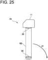
- a lid member 39 for restricting intrusion of sea water to the inside of the tower 8B may be provided for each of the root part 8r of the tower 8B and the tip part 8t of the tower 8B as illustrated in FIG. 25 for instance, before the collapsing step (S203).
- the lid members 39 may have a panel shape as depicted in the drawing, or may have a balloon shape (not depicted).
- the tower 8B when the tower 8B is cut and the body 2b of the wind turbine 2B is collapsed in the collapsing step, it is possible to suppress escape of air from the inside of the tower 8B due to intrusion of sea water to the inside of the tower 8B and allow the tower 8B to float on the sea water more easily.
- the body 2b of the wind turbine 2B it is possible to cause the body 2b of the wind turbine 2B to be less likely to sink under the sea water, and to reduce the buoyancy required for the structure 4 having a sheet shape or the float 28 for causing the body 2b of the wind turbine 2B to float on the sea water.
- a float member may be attached to the tower 8B instead of the lid member 39 to let the tower 8B float.
- the present disclosure is not limited to the meteorological tower 2A and wind turbine 2B, and is also applicable to a method for disassembling any offshore structure provided with a tower.
- the structure having a sheet shape is set beside the tower before cutting the tower, and then the tower is cut and the body of the offshore structure is collapsed toward the structure having a sheet shape. Accordingly, it is possible to prevent the body of the offshore structure from sinking under the sea by using the structure having a sheet shape and recover the body of the offshore structure. Furthermore, since the tower is cut off and the body of the offshore structure is collapsed toward the structure having a sheet shape, it is possible to reduce the amount of high place works compared to a case where the offshore structure is disassembled in high place works by setting up scaffolds around the tower while the tower is still standing, and thus it is possible to disassemble and recover the offshore structure safely.
- the setting step includes fixing the structure having a sheet shape while applying tension to the structure having a sheet shape using a ship (e.g., the above described ship 6) or an anchor (e.g., the above described anchor 20).
- a ship e.g., the above described ship 6
- an anchor e.g., the above described anchor 20
- the above method for disassembling an offshore structure (1) or (2) further includes a step of setting an oil fence (e.g., the above described oil fence 22) so as to surround the structure having a sheet shape before the collapsing step.
- an oil fence e.g., the above described oil fence 22
- the structure having a sheet shape to be set in the setting step has a smaller specific gravity than a specific gravity of sea water.
- a float e.g., the above described float 28
- the structure having a sheet shape to be set in the setting step is attached to the structure having a sheet shape to be set in the setting step.
- the transportation step includes transporting the structure having a sheet shape in a folded state
- the setting step includes expanding the structure having a sheet shape in a folded state and setting the same beside the tower.
- the structure having a sheet shape in a folded state is transported in the transportation step, which facilitates transportation of the structure having a sheet shape in the transportation step. Furthermore, the structure having a sheet shape in a folded state is expanded and set beside the tower in the setting step, which makes it possible to address to disassembling of a large-scale offshore structure.
- the recovery step includes towing the structure having a sheet shape on which the body of the offshore structure is loaded to land, and hoisting the body of the offshore structure up to the land.
- the collapsing step includes: a first irradiation step of irradiating the tower with a laser (e.g., the above described laser a1) from a first side of the tower in a horizontal direction so as not to penetrate the tower to form a first incision (e.g., the above described first incision C1) on the tower; a second irradiation step of irradiating the tower with a laser (e.g., the above described laser a2) at an angle different from that of the first incision from the first side of the tower in the horizontal direction so as not to penetrate the tower to form a second incision (e.g., the above described second incision C2) connecting to the first incision on the tower; and a third irradiation step of irradiating the tower with a laser (e.g., the above described laser a3) from a second side opposite to the first side of the tower
- the collapsing step includes cutting the tower while pulling the tower in two directions which are different from one another (e.g., the above described directions g1 and g2).
- the structure having a sheet shape comprises an oil adsorbent material (e.g., the above described polypropylene) which adsorbs oil.
- oil adsorbent material e.g., the above described polypropylene
- the offshore structure is a wind turbine (e.g., the above described wind turbine 2)
- the collapsing step includes collapsing a body of the wind turbine in the direction of a front side or a back side of the body of the wind turbine.
- any one of the above methods for disassembling an offshore structure (1) to (11) includes a step of providing a lid member (e.g., the above described lid member 39) for limiting intrusion of seawater into the tower on each of a root part (e.g., the above described root part 8r) of the tower and a tip part (e.g., the above described tip part 8t) of the tower before the collapsing step.
- a lid member e.g., the above described lid member 39
- a tip part e.g., the above described tip part 8t
- the method for disassembling an offshore structure described in the above (12) when the tower is cut and the body of the offshore structure is collapsed in the collapsing step, it is possible to suppress escape of air from the inside of the tower due to intrusion of sea water to the inside of the tower to allow the tower to float on the sea water more easily.
- the structure having a sheet shape has a membrane shape.
- the method for disassembling an offshore structure described in the above (13) it is possible to prevent the body of the offshore structure from sinking under the sea by using the structure having a membrane shape and recover the body of the offshore structure. Furthermore, since the tower is cut off and the body of the offshore structure is collapsed toward the structure having a membrane shape, it is possible to reduce the amount of high place works compared to a case where the offshore structure is disassembled in high place works by setting up scaffolds around the tower, and thus it is possible to disassemble and recover the offshore structure safely.
- the structure having a sheet shape has a net shape.
- the method for disassembling an offshore structure described in the above (14) it is possible to prevent the body of the offshore structure from sinking under the sea by using the structure having a net shape and recovering the body of the offshore structure. Furthermore, since the tower is cut off and the body of the offshore structure is collapsed toward the structure having a net shape, it is possible to reduce the amount of high place works compared to a case where the offshore structure is disassembled in high place works by setting up scaffolds around the tower, and thus it is possible to disassemble and recover the offshore structure safely.
- the setting step includes setting the structure having a sheet shape so as to surround the tower.
Landscapes
- Engineering & Computer Science (AREA)
- Mechanical Engineering (AREA)
- General Engineering & Computer Science (AREA)
- Transportation (AREA)
- Chemical & Material Sciences (AREA)
- Combustion & Propulsion (AREA)
- Ocean & Marine Engineering (AREA)
- Civil Engineering (AREA)
- Structural Engineering (AREA)
- Wind Motors (AREA)
- Foundations (AREA)
Abstract
Description
- The present disclosure relates to a method for disassembling an offshore structure provided with a tower of various facilities including an observation facility, a communication facility, an illuminating facility, a mining facility, a power generation facility, and the like (e.g., a meteorological tower, a transmission tower, a lighthouse, or an offshore wind turbine). The present application claims priority based on
Japanese Patent Application No. 2021-168036 filed on October 13, 2021 -
Patent Document 1 discloses a method for safely demolishing a taut mooring type floating body for mooring a floating structure, in relation to an offshore wind turbine provided with a floating structure. In this method, water is injected into a water injection part for submergence which is provided for the floating structure to submerge the floating structure, and the mooring cable is cut in a loosened state, thereby ensuring safety. -
Patent Document 2 discloses, as a method for disassembling a wind turbine without building a scaffold, a method of disassembling a tower sequentially from the top, using a crane apparatus disposed inside the tower of the wind turbine. -
- Patent Document 1:
JP2020-23233A - Patent Document 2:
WO2019/116511A - The inventors of the present invention have been researching, as a method for disassembling an offshore structure provided with a tower, a method of disassembling an offshore structure by cutting the root part of the tower by an explosive or a laser and then bringing down the body of the offshore structure (the part above the cutting position of the offshore structure) before disassembling, in order to minimize high place works. However, when the body of the offshore structure is to be collapsed, the body may sink under the sea where recovery is not possible.
- In view of the above, an object of at least one embodiment of the present disclosure is to provide a method for disassembling an offshore structure whereby it is possible to safely disassemble an offshore structure provided with a tower and recover the body of an offshore structure.
- To achieve the above object, a method for disassembling an offshore structure according to at least one embodiment of the present disclosure includes: a transportation step of transporting a structure having a sheet shape toward a tower of the offshore structure; a setting step of setting the structure having a sheet shape beside the tower; a collapsing step of cutting the tower and collapsing a body of the offshore structure toward the structure having a sheet shape; and a recovery step of recovering the body of the offshore structure.
- According to at least one embodiment of the present disclosure, it is possible to provide a method for disassembling an offshore structure whereby it is possible to safely disassemble and recover an offshore structure provided with a tower.
-
-
FIG. 1 is a flowchart schematically showing a method for disassembling ameteorological tower 2A according to an embodiment of the present disclosure. -
FIG. 2 is a diagram for describing an example of the transportation step (S101) illustrated inFIG. 1 . -
FIG. 3 is a planar view for describing an example of the setting step (S102) illustrated inFIG. 1 . -
FIG. 4 is a planar view for describing an example of the setting step (S102) illustrated inFIG. 1 . -
FIG. 5 is a diagram for describing an example of the collapsing step (S103) illustrated inFIG. 1 . -
FIG. 6 is a planar view for describing an example of the collapsing step (S103) illustrated inFIG. 1 . -
FIG. 7 is a diagram for describing another example of the collapsing step (S103) illustrated inFIG. 1 . -
FIG. 8 is a diagram for describing an example of the recovery step (S104) illustrated inFIG. 1 . -
FIG. 9 is a diagram for describing an example of using a net as astructure 4 having a sheet shape. -
FIG. 10 is a diagram illustrating a state in which the structure 4 (net) having a sheet shape is set so as to surround thetower 8A. -
FIG. 11 is a diagram illustrating a state in which thebody 2a of themeteorological tower 2A is enveloped with the structure 4 (net) having a sheet shape. -
FIG. 12 is a flowchart schematically showing a method for disassembling anoffshore wind turbine 2 according to an embodiment of the present disclosure. -
FIG. 13 is a diagram for describing an example of the transportation step (S201) illustrated inFIG. 12 . -
FIG. 14 is a diagram for describing an example of the setting step (S202) illustrated inFIG. 12 . -
FIG. 15 is a planar view for describing an example of the setting step (S202) illustrated inFIG. 12 . -
FIG. 16 is a planar view for describing an example of the setting step (S202) illustrated inFIG. 12 . -
FIG. 17 is a planar view for describing an example of the setting step (S202) illustrated inFIG. 12 . -
FIG. 18 is a diagram for describing an example of the collapsing step (S203) illustrated inFIG. 12 . -
FIG. 19 is a planar view for describing an example of the collapsing step (S203) illustrated inFIG. 12 . -
FIG. 20 is a diagram for describing an example of the collapsing step (S203) illustrated inFIG. 12 . -
FIG. 21 is a diagram for describing an example of the recovery step (S204) illustrated inFIG. 12 . -
FIG. 22 is a diagram for describing an example using a net as astructure 4 having a sheet shape. -
FIG. 23 is a diagram describing a state in which the structure 4 (net) having a sheet shape is set so as to surround thetower 8. -
FIG. 24 is a diagram describing a state in which thebody 2a of thewind turbine 2 is enveloped with the structure 4 (net) having a sheet shape. -
FIG. 25 is a diagram illustrating a state where thetower 8 is provided with alid member 39. - Embodiments of the present invention will now be described in detail with reference to the accompanying drawings. It is intended, however, that unless particularly identified, dimensions, materials, shapes, relative positions and the like of components described in the embodiments shall be interpreted as illustrative only and not intended to limit the scope of the present invention.
- For instance, an expression of relative or absolute arrangement such as "in a direction", "along a direction", "parallel", "orthogonal", "centered", "concentric" and "coaxial" shall not be construed as indicating only the arrangement in a strict literal sense, but also includes a state where the arrangement is relatively displaced by a tolerance, or by an angle or a distance whereby it is possible to achieve the same function.
- For instance, an expression of an equal state such as "same" "equal" and "uniform" shall not be construed as indicating only the state in which the feature is strictly equal, but also includes a state in which there is a tolerance or a difference that can still achieve the same function.
- Further, for instance, an expression of a shape such as a rectangular shape or a cylindrical shape shall not be construed as only the geometrically strict shape, but also includes a shape with unevenness or chamfered corners within the range in which the same effect can be achieved.
- On the other hand, an expression such as "comprise", "include", "have", "contain" and "constitute" are not intended to be exclusive of other components.
-
FIG. 1 is a flowchart schematically showing a method for disassembling a meteorological tower according to an embodiment of the present disclosure. - The disassembling method illustrated in
FIG. 1 includes a transportation step (S101) of transporting a structure having sheet shape toward a tower (column part) of a meteorological tower, a setting step (S102) of setting a structure having a sheet shape beside the tower, a collapsing step (S103) of cutting the tower and collapsing a body of the meteorological tower toward the structure having a sheet shape, and a recovery step (S104) of recovering the body of the meteorological tower. -
FIG. 2 is a diagram for describing an example of the transportation step (S101) illustrated inFIG. 1 . - As depicted in
FIG. 2 , themeteorological tower 2A includes atower 8A erected on afoundation 37 fixed to the seabed, and a plurality of branch-shaped protrusions 5 branched and extending from thetower 8A. Each of the branch-shaped protrusions 5 is provided with ameasurement instrument 9 for observing parameters related to meteorological phenomenon (e.g., wind direction, wind velocity, temperature, humidity, rainfall, or the like). - As illustrated in
FIG. 2 , in S101, thestructure 4 having a sheet shape is transported by aship 6 to the position where themeteorological tower 2A is installed. In S101, for instance, theship 6 may tow and transport thestructure 4 having a sheet shape, or, in a case where thestructure 4 having a sheet shape is foldable, thestructure 4 having a sheet shape may be transported in a folded state, by being towed or loaded on theship 6. - In the illustrated example, the
structure 4 having a sheet shape is a membranous structure (sheet) including afirst surface 4s (top surface) formed continuously in a flat shape and asecond surface 4t (bottom surface) formed continuously in a flat shape at the opposite side to thefirst surface 4s. - The material of the
structure 4 having a sheet shape may be a material that floats on the sea water, for instance, polyester, EVA (ethylene-vinyl acetate), polypropylene, or the like. The specific gravity of thestructure 4 having a sheet shape may be not greater than 1.02, such that thestructure 4 having a sheet shape floats on the sea water. - Moreover, the specific gravity of the
structure 4 having a sheet shape may be such a specific gravity that thestructure 4 having a sheet shape does not sink in a state where the body (described below) of themeteorological tower 2A is loaded on thestructure 4 having a sheet shape. Furthermore, the material of thestructure 4 having a sheet shape may be a material that does not float on the sea water, in which case a float (described below) formed of a material that floats on the sea water may be attached to thestructure 4 having a sheet shape. -
FIG. 3 is a diagram for describing an example of the setting step (S102) illustrated inFIG. 1 . - As illustrated in
FIG. 3 , in S102, thestructure 4 having a sheet shape is set beside thetower 8A. In the illustrated example, thestructure 4 having a sheet shape is set in the direction d1 in which thebody 2a of themeteorological tower 2A is to be collapsed, with respect to the position of thetower 8A. In the illustrated example, thestructure 4 having a sheet shape is floated on the sea surface beside thetower 8. Herein, thebody 2a of themeteorological tower 2A refers to the part of themeteorological tower 2A above the cutting position (described below) of thetower 8A, and includes, for instance, a part of thetower 8 and a part of the plurality of branch-shapedprotrusions 5. Furthermore, in a case where thestructure 4 having a sheet shape is transported in a folded state in S101, thestructure 4 having a sheet shape in a folded state is expanded and set beside thetower 8A in S102. Furthermore, "setting thestructure 4 having a sheet shape beside thetower 8A" means that, more specifically, setting thestructure 4 having a sheet shape on the sea in a certain direction with respect to thetower 8A such that the distance between thetower 8A and thestructure 4 having a sheet shape is less than 'h', where 'h' is the height of thetower 8A from the sea surface. - In S102, the
structure 4 having a sheet shape may be fixed in a state where tension is applied to thestructure 4 having a sheet shape with a plurality of ships 6 (seeFIG. 3 ) or a plurality of anchors 20 (seeFIG. 4 ) so that thestructure 4 having a sheet shape does not move in response to wind, wave, or the like. - In the example depicted in
FIG. 3 , four corners of thestructure 4 having a sheet shape that is rectangular in a planar view are fixed while being pulled in four directions by fourships 6 withropes 16 to apply tension. In the example depicted inFIG. 4 , taking into account the safety of theships 6, theanchors 20 are provided viaanchor cables 18 at the respective four corners of thestructure 4 having a sheet shape that is rectangular in a planar view, thereby fixing thestructure 4 having a sheet shape in a state where tension is applied to thestructure 4 having a sheet shape using theanchors 20. -
FIG. 5 is a diagram for describing an example of the collapsing step (S103) illustrated inFIG. 1 . The dotted line inFIG. 5 indicates the cutting position P1 for cutting thetower 8A in S103. - As depicted in
FIG. 5 , in S103, theroot part 8r of thetower 8A may be cut by a laser or an explosive, for instance, while at least oneship 6 pulls thetower 8A toward thestructure 4 having a sheet shape with arope 24 or the like. - In this case, as depicted in
FIG. 6 , thebody 2a of themeteorological tower 2A may be collapsed toward the direction d1 between two directions g1, g2 that are different from one another by cutting thetower 8A while pulling thetower 8A in the two different directions g1, g2 viaropes 24 with twoships 6. For instance, thebody 2a of themeteorological tower 2A may be collapsed toward the direction d1 in the middle of the two different directions g1, g2 by cutting thetower 8A while pulling thetower 8A from the two different directions g1, g2 viaropes 24 with twoships 6 at equal forces. As depicted inFIG. 6 , by cutting thetower 8A and collapsing thebody 2a of themeteorological tower 2A toward thestructure 4 having a sheet shape (in other words, by placing in advance thestructure 4 having a sheet shape in the direction d1 in which thebody 2a of themeteorological tower 2A is to be collapsed with respect to thetower 8A), it is possible to recover thebody 2a of themeteorological tower 2A easily by using thestructure 4 having a sheet shape. -
FIG. 7 is a diagram for describing another example of the collapsing step (S103) illustrated inFIG. 1 . - As depicted in
FIG. 7 , in step S103, the first incision C1, the second incision C2, and the third incision C3 may be formed on thetower 8A with a laser. - In the example depicted in
FIG. 7 , theroot part 8r of thetower 8A is irradiated with a laser a1 from the side of thetower 8A closer to thestructure 4 having a sheet shape (the first side) so as not to penetrate thetower 8A, and the first incision C1 is formed on the tower 8 (first irradiation step). Next, theroot part 8r of thetower 8A is irradiated with a laser a2 from the side of thetower 8A closer to thestructure 4 having a sheet shape so as not to penetrate thetower 8A at an angle different from that of the first incision C1, and the second incision C2 connecting to the first incision C1 is formed on thetower 8A, whereby a section (fragment) between the first incision C1 and the second incision C2 on thetower 8A is removed from the tower 8 (second irradiation step). Furthermore, theroot part 8r of thetower 8A is irradiated with a laser a3 from the opposite side (second side) of thetower 8A to thestructure 4 having a sheet shape, and the third incision C3 connecting to at least one of the first incision C1 or the second incision C2 is formed (third radiation step), whereby thetower 8A is cut off. In the illustrated example, each of the first incision C1 and the third incision C3 is formed on theroot part 8r of thetower 8A along the horizontal direction, and the second incision C2 is formed on theroot part 8r of thetower 8A from above toward the bottom diagonally. - By irradiating the
tower 8A with the lasers a1 to a3 as described above, it is possible to collapse thebody 2a of themeteorological tower 2A toward thestructure 4 having a sheet shape without pulling thetower 8A with ships. Thus, it is possible to recover thebody 2a of themeteorological tower 2A easily and safely using thestructure 4 having a sheet shape. - Furthermore, as depicted in
FIG. 5 , in the collapsing step, in a case where there is a direction in which the branch-shapedprotrusion 5 is not protruding from thetower 8A, the direction may be used as the collapsing direction d1. In this case, in a state where thebody 2a of themeteorological tower 2A is brought down, the direction in which the branch-shapedprotrusion 5 is not protruding from thetower 8A is facing downward. Furthermore, in a case where there is no direction in which the branch-shapedprotrusion 5 does not protrude from thetower 8A, the branch-shapedprotrusion 5 extending in the collapsing direction d1 may be cut and removed before cutting thetower 8A. Accordingly, it is possible to suppress breakage of thestructure 4 having a sheet shape due to the branch-shapedprotrusion 5. -
FIG. 8 is a diagram for describing an example of the recovery step (S104) illustrated inFIG. 1 . - As illustrated in
FIG. 8 , in step S104, thestructure 4 having a sheet shape on which thebody 2a of themeteorological tower 2A is loaded is transported to the shore, and thebody 2a of themeteorological tower 2A is hoisted up to the land and recovered. - In the example depicted in
FIG. 8 , thestructure 4 having a sheet shape on which thebody 2a of themeteorological tower 2A is loaded is towed by theship 6 to the shore, and then thebody 2a of themeteorological tower 2A is hoisted up to the land using acrane 26. In S104, thebody 2a of themeteorological tower 2A may be dismounted into a plurality of components on the sea such that the weight of each component to be hoisted up by thecrane 26 does not exceed the allowable load of thecrane 26. Furthermore, in a case where thebody 2a of themeteorological tower 2A is not dismounted but hoisted as a whole, a heavy crane or the like of a dock of a shipyard may be used to hoist up thebody 2a of themeteorological tower 2A, for instance. - Furthermore, in the example depicted in
FIG. 8 , a plurality offloats 28 are attached to anouter edge portion 4h of thestructure 4 having a sheet shape. The number of thefloats 28 may be determined such that thestructure 4 having a sheet shape does not sink in a state where thebody 2a of themeteorological tower 2A is loaded on thestructure 4 having a sheet shape. However, in a case where the specific gravity of thestructure 4 having a sheet shape is small enough such that thestructure 4 having a sheet shape does not sink in a state where thebody 2a of themeteorological tower 2A is loaded on, thefloats 28 may be omitted. - According to the above-described method for disassembling the
meteorological tower 2A, thestructure 4 having a sheet shape is set beside thetower 8A before cutting thetower 8A, and then thetower 8A is cut and thebody 2a of themeteorological tower 2A is collapsed toward thestructure 4 having a sheet shape. Accordingly, it is possible to prevent thebody 2a from themeteorological tower 2A from sinking under the sea by using thestructure 4 having a sheet shape and recovering thebody 2a of themeteorological tower 2A. Furthermore, since thetower 8A is cut off and thebody 2a of themeteorological tower 2A is collapsed toward thestructure 4 having a sheet shape, it is possible to reduce the amount of high place works compared to a case where themeteorological tower 2A is disassembled in high place works by building up scaffolds around thetower 8A while thetower 8A is still standing, and it is possible to disassemble and recover themeteorological tower 2A safely. Furthermore, by catching the collapsingbody 2a of themeteorological tower 2A with thestructure 4 having a sheet shape, it is possible to suppress occurrence of wave due to thebody 2a of themeteorological tower 2A, and suppress scattering of fragments and dusts of the structure, for instance, from thebody 2a of themeteorological tower 2A. - Furthermore, as described above with reference to
FIGs 3 and4 , by fixing thestructure 4 having a sheet shape while applying tension to thestructure 4 having a sheet shape using theships 6 or theanchors 20, it is possible to suppress movement of thestructure 4 having a sheet shape in response to wind or wave, for instance, and receive thebody 2a of themeteorological tower 2A collapsed in the collapsing step appropriately with thestructure 4 having a sheet shape for recovery. - Furthermore, in a case where the
structure 4 having a sheet shape is transported in a folded state and expanded to be set beside thetower 8A, it is possible to facilitate the transportation work for thestructure 4 having a sheet shape and receive a large-scale offshore structure such as themeteorological tower 2A with thestructure 4 having a sheet shape in an expanded state. - Next, some other embodiments will be described with reference to
FIGs. 9 to 11 . While thestructure 4 having a sheet shape described in the above described embodiment is a membranous structure including thefirst surface 4s formed continuously in a flat shape and thesecond surface 4t formed continuously in a flat shape at the opposite side to thefirst surface 4s, thestructure 4 having a sheet shape may be a net-shaped structure (net) as illustrated inFIG. 9 . Also in this case, it is possible to implement the method for disassembling themeteorological tower 2A described with reference toFIGs. 1 to 8 . - In a case where the
structure 4 having a sheet shape is a net-shaped structure, themeteorological tower 2A may be disassembled by the following disassembling method described with reference toFIGs. 10 and11 . In the method for disassembling themeteorological tower 2A described with reference toFIGs. 10 and11 , the basic flow is the same as the steps S101 to S104 illustrated inFIG. 1 , but the setting step in S102 and the recovery step in S104 are different from those in the above described embodiment. - In the embodiment depicted in
FIGs. 10 and11 , the step of transporting thestructure 4 having a sheet shape to the installation position of themeteorological tower 2A and the step of cutting and collapsing thetower 8A toward thestructure 4 having a sheet shape are the same as those in the embodiment described above with reference toFIG. 1 or the like, and thus not described in detail here. The following description will describe the step of setting thestructure 4 having a sheet shape and the step of transporting the body of themeteorological tower 2A to the shore using thestructure 4 having a sheet shape for recovery. - In the example depicted in
FIG. 10 , thestructure 4 having a sheet shape is a net, and a plurality offloats 28 are attached at intervals to theupper edge portion 4u of thestructure 4 having a sheet shape, and a plurality ofweights 23 are attached at intervals to thelower edge portion 4d of thestructure 4 having a sheet shape. Furthermore, arope 46 is passed through theupper edge portion 4u of thestructure 4 having a sheet shape, and arope 48 is passed through thelower edge portion 4d of the structure having a sheet shape. - In the example depicted in
FIG. 10 , in the setting step in step S102, thestructure 4 having a sheet shape is expanded around thetower 8A (beside thetower 8A) using theship 6 so as to surround thefoundation 37 of thetower 8A with thestructure 4 having a sheet shape. At this time, theship 6 expands thestructure 4 having a sheet shape by passing through the inside of thestructure 4 having a sheet shape so as to avoid thetower 8A. - Specifically, to begin with, the
ship 6 expands a longitudinal-direction firstend side portion 4a of thestructure 4 having a sheet shape for about a half round around thetower 8A along the first direction e1, which is one of the clockwise direction or the anticlockwise direction in a planar view. Next, theship 6 expands a longitudinal-directionintermediate portion 4b of thestructure 4 having a sheet shape along the second direction e2, which is the other one of the clockwise direction or the anticlockwise direction (opposite direction to the first direction e1) in a planar view, for about a single round along the outer peripheral surface of thetower 8A at the inner peripheral side of the longitudinal-direction firstend side portion 4a of thestructure 4 having a sheet shape. Next, theship 6 expands a longitudinal-direction secondend side portion 4c of thestructure 4 having a sheet shape for about a half round along the above first direction e1 at the outer peripheral side of the longitudinal-directionintermediate portion 4b of thestructure 4 having a sheet shape. Then, the overlapping portion of the longitudinal-directionintermediate portion 4b at the first side with respect to thetower 8A is fixed (bonded) by using at least onefixture 40 at one location or two locations at different distances from thetower 8A. The one or two locations for fixing by thefixture 40 should be preferably at the opposite side to the collapsing direction d1 of thebody 2a of themeteorological tower 2A so that thebody 2a of themeteorological tower 2A can be readily enveloped with thestructure 4 having a sheet shape when the fixing is released afterward. - Accordingly, in a planar view, the longitudinal-direction
intermediate portion 4b of thestructure 4 having a sheet shape is disposed so as to surround thetower 8A, and a combination of the longitudinal-direction firstend side portion 4a and the longitudinal-direction secondend side portion 4c of thestructure 4 having a sheet shape is disposed so as to surround thetower 8A at the radially outer side of the longitudinal-directionintermediate portion 4b. That is, the longitudinal-directionintermediate portion 4b of thestructure 4 having a sheet shape forms a radiallyinner ring 42 which surrounds thetower 8A, and the combination of the longitudinal-direction firstend side portion 4a and the longitudinal-direction secondend side portion 4c of thestructure 4 having a sheet shape forms a radiallyouter ring 44 which surrounds the radiallyinner ring 42. - By setting the
structure 4 having a sheet shape as described above, it is possible to accommodate thebody 2a of themeteorological tower 2A between the radiallyinner ring 42 and the radiallyouter ring 44 when thetower 8A is cut and thebody 2a of themeteorological tower 2A is collapsed toward thestructure 4 having a sheet shape (to the opposite side of thefixture 40 in the illustrated example) in the collapsing step (S103). Furthermore, in the collapsing step, it is possible to ensure a large space for accommodating thebody 2a of themeteorological tower 2A inside thestructure 4 having a sheet shape (between the radiallyinner ring 42 and the radially outer ring 44) by pulling thestructure 4 having a sheet shape with ships toward a plurality of directions away from thetower 8A (four to five directions indicated by empty arrows inFIG. 10 , for instance) to maintain a state where thestructure 4 having a sheet shape is expanded, and cutting thetower 8 in the state. In a case where thefixture 40 is provided for a single location, the above side where the large space can be ensured is limited to the opposite side to thefixture 40, and thus it is possible to accommodate thebody 2a of themeteorological tower 2A inside thestructure 4 having a sheet shape readily by collapsing thebody 2a of themeteorological tower 2A toward the opposite side to thefixture 40. In a case where thefixture 40 is provided for two locations, it is possible to position the radiallyouter ring 44 farther from the radiallyinner ring 42 and ensure the large space in every direction, thereby increasing the flexibility with regard to the collapsing direction. - It is possible to prevent the collapsed structure from falling down to the seabed by pulling and drawing the
rope 48 passed through thelower edge portion 4d of thestructure 4 having a sheet shape with a ship until the lower part of thestructure 4 having a sheet shape closes, after expanding thestructure 4 having a sheet shape as described above and before the collapsing step (S203). - In the recovery step (S104) after the collapsing step, the two fixations by the
fixtures 40 are released, and therope 46 passing through theupper edge portion 4u (the side of the float 28) of thestructure 4 having a sheet shape and therope 48 passing through thelower edge portion 4d (the side of the weight 23) are pulled and drawn by the ship, whereby it is possible to form thestructure 4 having a sheet shape into a bag shape and envelope thebody 2a of themeteorological tower 2A with thestructure 4 having a sheet shape as depicted inFIG. 11 . Accordingly, it is possible to tow thebody 2a of themeteorological tower 2A to the land along with thestructure 4 having a sheet shape, in a state where thebody 2a of themeteorological tower 2A is enveloped with thestructure 4 having a sheet shape. Once the ship reaches the land, thebody 2a of themeteorological tower 2A is hoisted up to the land by a crane 26 (seeFIG. 10 ) while still being enveloped with thestructure 4 having a sheet shape. - In the embodiment depicted in
FIGs. 10 and11 , thestructure 4 having a sheet shape (net) is set so as to surround thetower 8A, and thus it is possible to accommodate thebody 2a of themeteorological tower 2A inside thestructure 4 having a sheet shape regardless of the direction in which thetower 8A collapses. Thus, it is possible to prevent thebody 2a of themeteorological tower 2A from sinking under the sea more reliably by using thestructure 4 having a sheet shape, and recover thebody 2a of thewind turbine 2 easily. -
FIG. 12 is a flowchart schematically showing a method for disassembling an offshore wind turbine according to an embodiment of the present disclosure. Hereinafter, an offshore wind turbine will be referred to as merely a wind turbine. - The disassembling method illustrated in
FIG. 12 includes a transportation step (S201) of transporting a structure having a sheet shape toward a tower of an offshore wind turbine, a setting step (S202) of setting a structure having a sheet shape beside the tower, a collapsing step (S203) of cutting the tower and collapsing the body of the wind turbine toward the structure having a sheet shape, and a recovery step (S204) of recovering the body of the wind turbine. -
FIG. 13 is a diagram for describing an example of the transportation step (S201) illustrated inFIG. 12 . - As depicted in
FIG. 13 , thewind turbine 2B includes atower 8B, awind turbine rotor 10, and anacelle 11. Thewind turbine rotor 10 includes a plurality ofblades 12 and ahub 14 to which the plurality ofblades 12 are attached. Thenacelle 11 supports thehub 14 rotatably. - As depicted in
FIG. 13 , in S201, thestructure 4 having a sheet shape is transported by aship 6 to the position where thewind turbine 2B is installed. In S201, for instance, theship 6 may tow and transport thestructure 4 having a sheet shape, or, in a case where thestructure 4 having a sheet shape is foldable, thestructure 4 having a sheet shape may be transported in a folded state, by being towed or loaded on theship 6. - In the illustrated example, the
structure 4 having a sheet shape is a membranous structure (sheet) including afirst surface 4s (top surface) formed continuously in a flat shape and asecond surface 4t (bottom surface) formed continuously in a flat shape at the opposite side to thefirst surface 4s. - The material of the
structure 4 having a sheet shape may be a material that floats on the sea water, for instance, polyester, EVA (ethylene-vinyl acetate), polypropylene, or the like. The specific gravity of thestructure 4 having a sheet shape may be not greater than 1.02, such that thestructure 4 having a sheet shape floats on the sea water. In particular, when thestructure 4 having a sheet shape is formed of an oil adsorption material (e.g., polypropylene or the like) that adsorbs oil, it is possible to recover oil with thestructure 4 having a sheet shape formed of an oil adsorption material even if the oil inside thebody 2b of thewind turbine 2B scatters or leaks after thebody 2b of thewind turbine 2B is collapsed in the collapsing step described below, whereby it is possible to suppress ocean pollution effectively. - Moreover, the specific gravity of the
structure 4 having a sheet shape may be such a specific gravity that thestructure 4 having a sheet shape does not sink in a state where the body (described below) of thewind turbine 2B is loaded on thestructure 4 having a sheet shape. Furthermore, the material of thestructure 4 having a sheet shape may be a material that does not float on the sea water, in which case a float (described below) formed of a material that floats on the sea water may be attached to thestructure 4 having a sheet shape. - In the example illustrated in
FIG. 13 , thewind turbine 2B is a monopile type wind turbine provided with afoundation 38 fixed to the seabed. Nevertheless, the method for disassembling awind turbine 2B according to the present disclosure is applicable to any type of wind turbine, including a fixed-foundation wind turbine such as the gravity base type, the monopile type, and the jacket type, and a floating wind turbine such as the semi-submersible type, the spar type, and the tension leg type, depicted inFIG. 14 . -
FIG. 15 is a diagram for describing an example of the setting step (S202) illustrated inFIG. 12 . - As illustrated in
FIG. 15 , in S202, thestructure 4 having a sheet shape is set beside thetower 8B. In the illustrated example, thestructure 4 having a sheet shape is set in the direction d1 in which thebody 2b of thewind turbine 2B is to be collapsed, with respect to the position of thetower 8B. In the illustrated example, thestructure 4 having a sheet shape is floated on the sea surface beside thetower 8B. Herein, thebody 2b of thewind turbine 2B refers to the section above the cutting position (described below) of thetower 8B of thewind turbine 2B, and includes thewind turbine rotor 10, the nacelle 11 (seeFIG. 13 ), and a part of thetower 8B. Furthermore, in a case where thestructure 4 having a sheet shape is transported in a folded state in S201, thestructure 4 having a sheet shape in a folded state is expanded and set beside thetower 8B in S202. Furthermore, "setting thestructure 4 having a sheet shape beside thetower 8B" means that, more specifically, setting thestructure 4 having a sheet shape on the sea in a certain direction with respect to thetower 8B such that the distance between thetower 8B and thestructure 4 having a sheet shape is less than 'h', where 'h' is the height of thetower 8B from the sea surface. - In S202, the
structure 4 having a sheet shape may be fixed in a state where tension is applied to thestructure 4 having a sheet shape with a plurality of ships 6 (seeFIG. 15 ) or a plurality of anchors 20 (seeFIG. 16 ) so that thestructure 4 having a sheet shape does not move in response to wind, wave, or the like. - In the example depicted in
FIG. 15 , four corners of thestructure 4 having a sheet shape that is rectangular in a planar view are fixed while being pulled in four directions by fourships 6 withropes 16 to apply tension. In the example depicted inFIG. 16 , taking into account the safety of theships 6, theanchors 20 are provided viaanchor cables 18 at the respective four corners of thestructure 4 having a sheet shape that is rectangular in a planar view, thereby fixing thestructure 4 having a sheet shape in a state where tension is applied to thestructure 4 having a sheet shape using theanchors 20. - In S202, as illustrated in
FIG. 16 for instance, anoil fence 22 may be set so as to surround thestructure 4 having a sheet shape. Furthermore, while theoil fence 22 is set so as to surround thetower 8B and thestructure 4 having a sheet shape in the example illustrated inFIG. 16 , theoil fence 22 may be set so as to surround only thestructure 4 having a sheet shape and not thetower 8B. - Furthermore, in a case where the
wind turbine 2B is a semi-submersible type (seeFIG. 14 ) offshore wind turbine, as illustrated inFIG. 17 for instance, the shape of thestructure 4 having a sheet shape may be a shape conforming to the shape of the floatingbody 30 of thewind turbine 2B in a planar view. In the example depicted inFIG. 17 , the floatingbody 30 includes threelower hulls 32, and in a planar view, the threelower hulls 32 extend from the position of thetower 8B in respective directions that are different from one another by 120 angular degrees. Furthermore, in the example depicted inFIG. 17 , thestructure 4 having a sheet shape has a pentagonal shape including two sides that extend along the twolower hulls 32 of the threelower hulls 32 in a planar view, and the two sides make an angle of 120 degrees. -
FIG. 18 is a diagram for describing an example of the collapsing step (S203) illustrated inFIG. 12 . The dotted line inFIG. 18 indicates the cutting position P1 for cutting thetower 8B in S203. - As depicted in
FIG. 18 , in S203, theroot part 8r of thetower 8B may be cut by a laser or an explosive, for instance, while at least oneship 6 pulls thetower 8B toward thestructure 4 having a sheet shape with therope 24 or the like. - In this case, as depicted in
FIG. 19 for instance, thebody 2b of thewind turbine 2B may be collapsed toward the direction d1 between two directions g1, g2 that are different from one another by cutting thetower 8B while pulling thetower 8B in the two different directions g1, g2 with twoships 6 via theropes 24. For instance, thebody 2b of thewind turbine 2B may be collapsed toward the direction d1 in the middle of the two different directions g1, g2 by cutting thetower 8B while pulling thetower 8B from the two different directions g1, g2 at equal forces with the twoships 6 via theropes 24 As depicted inFIG. 19 , by cutting thetower 8B and collapsing thebody 2b of thewind turbine 2B toward thestructure 4 having a sheet shape (in other words, by placing in advance thestructure 4 having a sheet shape in the direction d1 in which thebody 2b of thewind turbine 2B is to be collapsed with respect to thetower 8B), it is possible to recover thebody 2b of thewind turbine 2B easily by using thestructure 4 having a sheet shape. -
FIG. 20 is a diagram for describing another example of the collapsing step (S203) illustrated inFIG. 12 . - As depicted in
FIG. 20 , in step S203, the first incision C1, the second incision C2, and the third incision C3 may be formed with a laser. - In the example depicted in
FIG. 20 , theroot part 8r of thetower 8B is irradiated with a laser a1 from the side of thetower 8B closer to thestructure 4 having a sheet shape (the first side) so as not to penetrate thetower 8B, and the first incision C1 is formed on thetower 8B (first irradiation step). Next, theroot part 8r of thetower 8B is irradiated with a laser a2 from the side of thetower 8B closer to thestructure 4 having a sheet shape so as not to penetrate thetower 8B at an angle different from that of the first incision C1, and the second incision C2 connecting to the first incision C1 is formed on thetower 8B, whereby a section (fragment) between the first incision C1 and the second incision C2 on thetower 8B is removed from thetower 8B (second irradiation step). Furthermore, theroot part 8r of thetower 8B is irradiated with a laser a3 from the opposite side (second side) of thetower 8B to thestructure 4 having a sheet shape, and the third incision C3 connecting to at least one of the first incision C1 or the second incision C2 is formed (third irradiation step), whereby thetower 8B is cut off. In the illustrated example, each of the first incision C1 and the third incision C3 is formed on theroot part 8r of thetower 8B along the horizontal direction, and the second incision C2 is formed on theroot part 8r of thetower 8B from above toward the bottom diagonally. - By irradiating the
tower 8B with the lasers a1 to a3 as described above, it is possible to collapse thebody 2b of thewind turbine 2B toward thestructure 4 having a sheet shape without pulling thetower 8B with ships. Thus, it is possible to recover thebody 2b of thewind turbine 2B easily and safely using thestructure 4 having a sheet shape. - Furthermore, in the collapsing step described with reference to
FIGs. 18 to 20 , it is desirable to collapse thebody 2b of thewind turbine 2B in the direction of the front side or the back side of thebody 2b of thewind turbine 2B. Accordingly, it is possible to suppress breakage of thestructure 4 having a sheet shape due to the blades 12b of thewind turbine 2B. Herein, the front side and the back side of thebody 2b of thewind turbine 2B refer to the front side (upwind side) and the rear side (downwind side) along the rotational axis of thewind turbine rotor 10, in a case where the wind turbine is a horizontal-axis wind turbine. -
FIG. 21 is a diagram for describing an example of the recovery step (S204) illustrated inFIG. 12 . - As illustrated in
FIG. 21 , in step S204, thestructure 4 having a sheet shape on which thebody 2b of thewind turbine 2B is loaded is transported to the shore, and thebody 2b of thewind turbine 2B is hoisted up to the land and recovered. - In the example depicted in
FIG. 21 , thestructure 4 having a sheet shape on which thebody 2b of thewind turbine 2B is loaded is towed by theship 6 to the shore, and then thebody 2b of thewind turbine 2B is hoisted up to the land using acrane 26. In S204, thebody 2b of thewind turbine 2B may be dismounted into a plurality of components on the sea such that the weight of each component to be hoisted up by thecrane 26 does not exceed the allowable load of thecrane 26. Furthermore, in a case where thebody 2b of a large-scale wind turbine 2B is not dismounted but hoisted as a whole, a heavy crane or the like of a dock of a shipyard may be used to hoist up thebody 2b of thewind turbine 2B, for instance. - Furthermore, in the example depicted in
FIG. 21 , a plurality offloats 28 are attached to anouter edge portion 4h of thestructure 4 having a sheet shape. The number of thefloats 28 may be determined such that thestructure 4 having a sheet shape does not sink in a state where thebody 2b of thewind turbine 2B is loaded on thestructure 4 having a sheet shape. However, in a case where the specific gravity of thestructure 4 having a sheet shape is small enough such that thestructure 4 having a sheet shape does not sink in a state where thebody 2b of thewind turbine 2B is loaded on, thefloats 28 may be omitted. - According to the above-described method for disassembling the
wind turbine 2B, thestructure 4 having a sheet shape is set beside thetower 8B before cutting thetower 8B, and then thetower 8B is cut and the body of thewind turbine 2B is collapsed toward thestructure 4 having a sheet shape. Accordingly, it is possible to prevent thebody 2b of thewind turbine 2B from sinking under the sea by using thestructure 4 having a sheet shape and recover thebody 2b of thewind turbine 2B. Furthermore, since thetower 8B is cut off and thebody 2b of thewind turbine 2B is collapsed toward thestructure 4 having a sheet shape, it is possible to reduce the amount of high place works compared to a case where thewind turbine 2B is disassembled in high place works by building up scaffolds around thetower 8B while thetower 8B is still standing, and it is possible to disassemble and recover thewind turbine 2B safely. Furthermore, by catching the collapsingbody 2b of thewind turbine 2B with thestructure 4 having a sheet shape, it is possible to suppress occurrence of wave due to thebody 2b of thewind turbine 2B, and suppress scattering and leakage of oil, for instance, from thebody 2b of thewind turbine 2B. - Furthermore, as described above with reference to
FIGs. 15 and16 , by fixing thestructure 4 having a sheet shape while applying tension to thestructure 4 having a sheet shape using theships 6 or theanchors 20, it is possible to suppress movement of thestructure 4 having a sheet shape in response to wind or wave, for instance, and receive thebody 2b of thewind turbine 2B collapsed in the collapsing step appropriately with thestructure 4 having a sheet shape for recovery. - Furthermore, as described above with reference to
FIG. 16 , by setting theoil fence 22 so as to surround thestructure 4 having a sheet shape before the collapsing step (S203), it is possible to recover oil with theoil fence 22 even if oil inside thewind turbine 2B scatters or leaks when or after thebody 2b of thewind turbine 2B is collapsed, whereby it is possible to suppress ocean pollution. - In a case where the structure having a sheet shape is transported in a folded state and expanded to be set beside the tower, it is possible to facilitate the transportation work for the structure having a sheet shape and receive a large-scale offshore structure such as the
wind turbine 2B with thestructure 4 having a sheet shape in an expanded state. - Next, some other embodiments will be described with reference to
FIGs. 22 to 24 . While thestructure 4 having a sheet shape described in the above described embodiment is a membranous structure including afirst surface 4s formed continuously in a flat shape and asecond surface 4t formed continuously in a flat shape at the opposite side to thefirst surface 4s, thestructure 4 having a sheet shape may be a net-shaped structure (net) as illustrated inFIG. 22 . Also in this case, it is possible to implement the method for disassembling thewind turbine 2B described with reference toFIGs. 12 to 21 . - In a case where the
structure 4 having a sheet shape is a net-shaped structure, thewind turbine 2B may be disassembled by the following disassembling method described with reference toFIGs. 23 and24 . In the method for disassembling thewind turbine 2B described with reference toFIGs. 23 and24 , the basic flow is the same as the steps S201 to S204 illustrated inFIG. 12 , but the setting step in S202 and the recovery step in S204 are different from those in the above described embodiment. - In the embodiment depicted in
FIGs. 23 and24 , the step of transporting thestructure 4 having a sheet shape to the setting position of thewind turbine 2B and the step of cutting and collapsing thetower 8B toward thestructure 4 having a sheet shape are the same as those in the embodiment described above with reference toFIG. 12 or the like, and thus not described in detail here. The following description will describe the step of setting thestructure 4 having a sheet shape and the step of transporting the body of thewind turbine 2B using thestructure 4 having a sheet shape to the shore for recovery. - In the example depicted in
FIG. 23 , thestructure 4 having a sheet shape is a net, and a plurality offloats 28 are attached at intervals to theupper edge portion 4u of thestructure 4 having a sheet shape, and a plurality ofweights 23 are attached at intervals to thelower edge portion 4d of thestructure 4 having a sheet shape. Furthermore, arope 46 is passed through theupper edge portion 4u of thestructure 4 having a sheet shape, and arope 48 is passed through thelower edge portion 4d of thestructure 4 having a sheet shape. - In the example depicted in
FIG. 23 , in the setting step in step S202, thestructure 4 having a sheet shape is expanded around thetower 8B (beside thetower 8B) using theship 6 so as to surround thefoundation 38 of thetower 8B with thestructure 4 having a sheet shape. At this time, theship 6 expands thestructure 4 having a sheet shape by passing through the inside of thestructure 4 having a sheet shape so as to avoid thetower 8B. - Specifically, to begin with, the
ship 6 expands a longitudinal-direction firstend side portion 4a of thestructure 4 having a sheet shape for about a half round around thetower 8B along the first direction e1, which is one of the clockwise direction or the anticlockwise direction in a planar view. Next, theship 6 expands a longitudinal-directionintermediate portion 4b of thestructure 4 having a sheet shape along the second direction e2, which is the other one of the clockwise direction or the anticlockwise direction (opposite direction to the first direction e1) in a planar view, for about a single round along the outer peripheral surface of thetower 8B at the inner peripheral side of the longitudinal-direction firstend side portion 4a of thestructure 4 having a sheet shape. Next, theship 6 expands a longitudinal-direction secondend side portion 4c of thestructure 4 having a sheet shape for about a half round along the above first direction e1 at the outer peripheral side of the longitudinal-directionintermediate portion 4b of thestructure 4 having a sheet shape. Then, the overlapping portion of the longitudinal-directionintermediate portion 4b at the first side with respect to thetower 8B is fixed (bonded) by using at least onefixture 40 at one location or two locations at different distances from thetower 8B. The one or two locations for fixing by thefixture 40 should be preferably at the opposite side to the collapsing direction d1 of thebody 2b of thewind turbine 2B so that thebody 2a of thewind turbine 2B can be readily enveloped with thestructure 4 having a sheet shape when the fixing is released afterward. - Accordingly, in a planar view, the longitudinal-direction
intermediate portion 4b of thestructure 4 having a sheet shape is disposed so as to surround thetower 8B, and a combination of the longitudinal-direction firstend side portion 4a and the longitudinal-direction secondend side portion 4c of thestructure 4 having a sheet shape is disposed so as to surround thetower 8B at the radially outer side of the longitudinal-directionintermediate portion 4b. That is, the longitudinal-directionintermediate portion 4b of thestructure 4 having a sheet shape forms a radiallyinner ring 42 which surrounds thetower 8B, and the combination of the longitudinal-direction firstend side portion 4a and the longitudinal-direction secondend side portion 4c of thestructure 4 having a sheet shape forms a radiallyouter ring 44 which surrounds the radiallyinner ring 42. - By setting the
structure 4 having a sheet shape as described above, it is possible to accommodate thebody 2b of thewind turbine 2B between the radiallyinner ring 42 and the radiallyouter ring 44 when thetower 8B is cut and thebody 2b of thewind turbine 2B is collapsed toward thestructure 4 having a sheet shape (to the opposite side of thefixture 40 in the illustrated example) in the collapsing step (S203). Furthermore, in the collapsing step, it is possible to ensure a large space for accommodating thebody 2b of thewind turbine 2B inside thestructure 4 having a sheet shape (between the radiallyinner ring 42 and the radially outer ring 44) by pulling thestructure 4 having a sheet shape and theoil fence 22 with ships toward a plurality of directions away from thetower 8B (four to five directions indicated by empty arrows inFIG. 23 , for instance) to maintain a state where thestructure 4 having a sheet shape and theoil fence 22 are expanded, and cutting thetower 8B in the state. In a case where thefixture 40 is provided for a single location, the above side where the large space can be ensured is limited to the opposite side to thefixture 40, and thus it is possible to accommodate thebody 2a of thewind turbine 2B inside thestructure 4 having a sheet shape readily by collapsing thebody 2b of thewind turbine 2B toward the opposite side to thefixture 40. In a case where thefixture 40 is provided for two locations, it is possible to position the radiallyouter ring 44 farther from the radiallyinner ring 42 and ensure the large space in every direction, thereby increasing the flexibility with regard to the collapsing direction. - It is possible to prevent the collapsed structure from falling down to the seabed by pulling and drawing the
rope 48 passed through thelower edge portion 4d of thestructure 4 having a sheet shape with a ship until the lower part of thestructure 4 having a sheet shape closes, after expanding thestructure 4 having a sheet shape as described above and before the collapsing step (S203). - In the recovery step (S204) after the collapsing step, the two fixations by the
fixtures 40 are released, and therope 46 passing through theupper edge portion 4u (the side of the float 28) of thestructure 4 having a sheet shape and therope 48 passing through thelower edge portion 4d (the side of the weight 23) are pulled and drawn by the ship, whereby it is possible to form thestructure 4 having a sheet shape into a bag shape and envelope thebody 2b of thewind turbine 2B with thestructure 4 having a sheet shape as depicted inFIG. 24 . Accordingly, it is possible to tow thebody 2b of thewind turbine 2B to the land along with thestructure 4 having a sheet shape, in a state where thebody 2b of thewind turbine 2B is enveloped with thestructure 4 having a sheet shape. Once the ship reaches the land, thebody 2b of thewind turbine 2B is hoisted up to the land by a crane 26 (seeFIG. 21 ) while still being enveloped with thestructure 4 having a sheet shape. - In the embodiment depicted in
FIGs. 23 and24 , thestructure 4 having a sheet shape (net) is set so as to surround thetower 8B, and thus it is possible to accommodate thebody 2b of thewind turbine 2B inside thestructure 4 having a sheet shape regardless of the direction in which thetower 8B collapses. Thus, it is possible to prevent thebody 2b of thewind turbine 2B from sinking under the sea more reliably by using thestructure 4 having a sheet shape, and recover thebody 2b of thewind turbine 2B easily. - Embodiments of the present invention were described in detail above, but the present invention is not limited thereto, and various amendments and modifications may be implemented.
- For instance, in the embodiment illustrated in
FIG. 23 or the like, therope 48 passing through thelower edge portion 4d of thestructure 4 having a sheet shape (net) may be pulled and drawn by ships in advance before the collapsing step (S203). Accordingly, it is possible to recover thebody 2b of thewind turbine 2B more reliably with thestructure 4 having a sheet shape. - Furthermore, for instance, while the recovery step (S204) illustrated in
FIG. 21 includes transporting thestructure 4 having a sheet shape on which thebody 2b of thewind turbine 2B is loaded and hoisting thebody 2b of thewind turbine 2B up to the land for recovery, in another embodiment, thebody 2b of thewind turbine 2B may be disassembled for recovery by using a ship with a heavy machine (not depicted) before transporting thebody 2b of thewind turbine 2B to the land, after the collapsing step (S203). - Furthermore, for instance, in each of the above described embodiments, a
lid member 39 for restricting intrusion of sea water to the inside of thetower 8B may be provided for each of theroot part 8r of thetower 8B and the tip part 8t of thetower 8B as illustrated inFIG. 25 for instance, before the collapsing step (S203). Thelid members 39 may have a panel shape as depicted in the drawing, or may have a balloon shape (not depicted). - Accordingly, when the
tower 8B is cut and thebody 2b of thewind turbine 2B is collapsed in the collapsing step, it is possible to suppress escape of air from the inside of thetower 8B due to intrusion of sea water to the inside of thetower 8B and allow thetower 8B to float on the sea water more easily. Thus, it is possible to cause thebody 2b of thewind turbine 2B to be less likely to sink under the sea water, and to reduce the buoyancy required for thestructure 4 having a sheet shape or thefloat 28 for causing thebody 2b of thewind turbine 2B to float on the sea water. Furthermore, it is possible to suppress scattering or leakage of oil or dust or the like inside thetower 8B of thewind turbine 2B to the outside of thetower 8B. - Moreover, it is desirable to dispose the
lid member 39 for theroot part 8r above the cutting position P1 (seeFIG. 18 , for instance) of thetower 8B and at a position appropriately distanced from the cutting position PI, such that thelid member 39 is not affected by the explosive or the laser used on thetower 8B, for instance, in the collapsing step. Furthermore, in another embodiment, a float member may be attached to thetower 8B instead of thelid member 39 to let thetower 8B float. - Furthermore, while the above described embodiments describe the method for disassembling the
meteorological tower 2A and the method for disassembling thewind turbine 2B, the present disclosure is not limited to themeteorological tower 2A andwind turbine 2B, and is also applicable to a method for disassembling any offshore structure provided with a tower. - The contents described in the above respective embodiments can be understood as follows, for instance.
- (1) According to at least one embodiment of the present disclosure, a method for disassembling an offshore structure (e.g., the above described
meteorological tower 2A or thewind turbine 2B) includes: a transportation step of transporting a structure having a sheet shape (e.g., the above describedstructure 4 having a sheet shape) toward a tower (e.g., the above describedtower 8A ortower 8B) of the offshore structure; a setting step of setting the structure having a sheet shape beside the tower; a collapsing step of cutting the tower and collapsing a body (e.g., the above describedbody 2a orbody 2b) of the offshore structure toward the structure having a sheet shape; and a recovery step of recovering the body of the offshore structure. - According to the above method for disassembling an offshore structure, the structure having a sheet shape is set beside the tower before cutting the tower, and then the tower is cut and the body of the offshore structure is collapsed toward the structure having a sheet shape. Accordingly, it is possible to prevent the body of the offshore structure from sinking under the sea by using the structure having a sheet shape and recover the body of the offshore structure. Furthermore, since the tower is cut off and the body of the offshore structure is collapsed toward the structure having a sheet shape, it is possible to reduce the amount of high place works compared to a case where the offshore structure is disassembled in high place works by setting up scaffolds around the tower while the tower is still standing, and thus it is possible to disassemble and recover the offshore structure safely.
- (2) In some embodiments, in the above method for disassembling an offshore structure (1), the setting step includes fixing the structure having a sheet shape while applying tension to the structure having a sheet shape using a ship (e.g., the above described ship 6) or an anchor (e.g., the above described anchor 20).
- According to the above method for disassembling an offshore structure (2), it is possible to suppress movement of the structure having a sheet shape in response to wind, wave, or the like, and thus it is possible to receive and recover the body of the offshore structure collapsed in the collapsing step with the structure having a sheet shape appropriately.
- (3) In some embodiments, the above method for disassembling an offshore structure (1) or (2) further includes a step of setting an oil fence (e.g., the above described oil fence 22) so as to surround the structure having a sheet shape before the collapsing step.
- According to the method for disassembling an offshore structure according to the above (3), it is possible to recover oil with the oil fence even if the oil inside the offshore structure scatters or leaks when and after the body of the offshore structure is collapsed, and thus it is possible to suppress ocean pollution.
- (4) In some embodiments, in any one of the above methods for disassembling an offshore structure (1) to (3), the structure having a sheet shape to be set in the setting step has a smaller specific gravity than a specific gravity of sea water.
- According to the method for disassembling an offshore structure described in the above (4), it is possible to utilize buoyancy of the structure having a sheet shape to prevent the body of the offshore structure from sinking under the sea, which makes recovery of the offshore structure easier.
- (5) In some embodiments, in any one of the above methods for disassembling an offshore structure (1) to (4), a float (e.g., the above described float 28) is attached to the structure having a sheet shape to be set in the setting step.
- According to the method for disassembling an offshore structure described in the above (5), it is possible to utilize buoyancy of the float to prevent the body of the offshore structure from sinking under the sea, which makes recovery of the offshore structure easier.
- (6) In some embodiments, in any one of the above methods for disassembling an offshore structure (1) to (5), the transportation step includes transporting the structure having a sheet shape in a folded state, and the setting step includes expanding the structure having a sheet shape in a folded state and setting the same beside the tower.
- According to the method for disassembling an offshore structure described in the above (6), the structure having a sheet shape in a folded state is transported in the transportation step, which facilitates transportation of the structure having a sheet shape in the transportation step. Furthermore, the structure having a sheet shape in a folded state is expanded and set beside the tower in the setting step, which makes it possible to address to disassembling of a large-scale offshore structure.
- (7) In some embodiments, in any one of the above methods for disassembling an offshore structure (1) to (6), the recovery step includes towing the structure having a sheet shape on which the body of the offshore structure is loaded to land, and hoisting the body of the offshore structure up to the land.
- According to the method for disassembling an offshore structure described in the above (7), it is possible to recover the body of the offshore structure to the land safely.
- (8) In some embodiments, in any one of the above methods for disassembling an offshore structure (1) to (7), the collapsing step includes: a first irradiation step of irradiating the tower with a laser (e.g., the above described laser a1) from a first side of the tower in a horizontal direction so as not to penetrate the tower to form a first incision (e.g., the above described first incision C1) on the tower; a second irradiation step of irradiating the tower with a laser (e.g., the above described laser a2) at an angle different from that of the first incision from the first side of the tower in the horizontal direction so as not to penetrate the tower to form a second incision (e.g., the above described second incision C2) connecting to the first incision on the tower; and a third irradiation step of irradiating the tower with a laser (e.g., the above described laser a3) from a second side opposite to the first side of the tower in the horizontal direction to form a third incision (e.g., the above described third incision C3) connecting to at least one of the first incision or the second incision.
- According to the method for disassembling an offshore structure described in the above (8), it is possible to collapse the body of the offshore structure toward the structure having a sheet shape without pulling the tower with a ship. Thus, it is possible to recover the body of the offshore structure easily and safely using the structure having a sheet shape.
- (9) In some embodiments, in the above method for disassembling an offshore structure (8), the collapsing step includes cutting the tower while pulling the tower in two directions which are different from one another (e.g., the above described directions g1 and g2).
- According to the method for disassembling an offshore structure described in the above (9), by cutting the tower while pulling the tower in the two different directions with an appropriate force, it is possible to collapse the body of the offshore structure in the intended direction between the two different directions. Thus, it is possible to recover the body of the offshore structure easily using the structure having a sheet shape.
- (10) In some embodiments, in any one of the above methods for disassembling an offshore structure (1) to (9), the structure having a sheet shape comprises an oil adsorbent material (e.g., the above described polypropylene) which adsorbs oil.
- According to the method for disassembling an offshore structure according to the above (10), it is possible to recover oil with the structure having a sheet shape formed of an oil adsorption material even if the oil inside the offshore structure scatters or leaks after the body of the offshore structure is collapsed, and thus it is possible to suppress ocean pollution.
- (11) In some embodiments, in any one of the above methods for disassembling an offshore structure (1) to (10), the offshore structure is a wind turbine (e.g., the above described wind turbine 2), and the collapsing step includes collapsing a body of the wind turbine in the direction of a front side or a back side of the body of the wind turbine.
- According to the method for disassembling an offshore structure described in the above (11), by collapsing the body of the wind turbine in the direction of the front side or the back side of the body of the wind turbine, it is possible to suppress breakage of the structure having a sheet shape due to the blades of the wind turbine.
- (12) In some embodiments, any one of the above methods for disassembling an offshore structure (1) to (11) includes a step of providing a lid member (e.g., the above described lid member 39) for limiting intrusion of seawater into the tower on each of a root part (e.g., the above described
root part 8r) of the tower and a tip part (e.g., the above described tip part 8t) of the tower before the collapsing step. - According to the method for disassembling an offshore structure described in the above (12), when the tower is cut and the body of the offshore structure is collapsed in the collapsing step, it is possible to suppress escape of air from the inside of the tower due to intrusion of sea water to the inside of the tower to allow the tower to float on the sea water more easily. Thus, it is possible to make the body of the offshore structure less likely to sink under the sea water, and to reduce the buoyancy required for the structure having a sheet shape and the float to let the body of the offshore structure float on the sea water. Furthermore, it is possible to suppress scattering or leakage of oil or dust or the like inside the tower of the wind turbine to the outside of the tower.
- (13) In some embodiments, in any one of the above methods for disassembling an offshore structure (1) to (12), the structure having a sheet shape has a membrane shape.
- According to the method for disassembling an offshore structure described in the above (13), it is possible to prevent the body of the offshore structure from sinking under the sea by using the structure having a membrane shape and recover the body of the offshore structure. Furthermore, since the tower is cut off and the body of the offshore structure is collapsed toward the structure having a membrane shape, it is possible to reduce the amount of high place works compared to a case where the offshore structure is disassembled in high place works by setting up scaffolds around the tower, and thus it is possible to disassemble and recover the offshore structure safely.
- (14) In some embodiments, in any one of the above methods for disassembling an offshore structure (1) to (12), the structure having a sheet shape has a net shape.
- According to the method for disassembling an offshore structure described in the above (14), it is possible to prevent the body of the offshore structure from sinking under the sea by using the structure having a net shape and recovering the body of the offshore structure. Furthermore, since the tower is cut off and the body of the offshore structure is collapsed toward the structure having a net shape, it is possible to reduce the amount of high place works compared to a case where the offshore structure is disassembled in high place works by setting up scaffolds around the tower, and thus it is possible to disassemble and recover the offshore structure safely.
- (15) In some embodiments, in any one of the above methods for disassembling an offshore structure (1) to (14), the setting step includes setting the structure having a sheet shape so as to surround the tower.
- According to the method for disassembling an offshore structure described in the above (15), it is possible to accommodate the body of the offshore structure inside the structure having a sheet shape regardless of the direction in which the tower collapses. Thus, it is possible to prevent the body of the offshore structure from sinking under the sea more reliably by using the structure having a sheet shape.
Claims (15)
- A method for disassembling an offshore structure, the method comprising:a transportation step of transporting a structure having a sheet shape toward a tower of the offshore structure;a setting step of setting the structure having a sheet shape beside the tower;a collapsing step of cutting the tower and collapsing a body of the offshore structure toward the structure having a sheet shape; anda recovery step of recovering the body of the offshore structure.
- The method for disassembling an offshore structure according to claim 1,
wherein the setting step includes fixing the structure having a sheet shape while applying tension to the structure having a sheet shape using a ship or an anchor. - The method for disassembling an offshore structure according to claim 1 or 2, the method further comprising:
a step of setting an oil fence so as to surround the structure having a sheet shape before the collapsing step. - The method for disassembling an offshore structure according to any one of claims 1 to 3,
wherein the structure having a sheet shape to be set in the setting step has a smaller specific gravity than a specific gravity of sea water. - The method for disassembling an offshore structure according to any one of claims 1 to 4,
wherein a float is attached to the structure having a sheet shape to be set in the setting step. - The method for disassembling an offshore structure according to any one of claims 1 to 5,wherein the transportation step includes transporting the structure having a sheet shape in a folded state, andwherein the setting step includes expanding the structure having a sheet shape in a folded state and setting the same beside the tower.
- The method for disassembling an offshore structure according to any one of claims 1 to 6,
wherein the recovery step includes towing the structure having a sheet shape on which the body of the offshore structure is loaded to land, and hoisting the body of the offshore structure up to the land. - The method for disassembling an offshore structure according to any one of claims 1 to 7,
wherein the collapsing step includes:a first irradiation step of irradiating the tower with a laser from a first side of the tower in a horizontal direction so as not to penetrate the tower to form a first incision on the tower;a second irradiation step of irradiating the tower with a laser at an angle different from that of the first incision from the first side of the tower in the horizontal direction so as not to penetrate the tower to form a second incision connecting to the first incision on the tower; anda third irradiation step of irradiating the tower with a laser from a second side opposite to the first side of the tower in the horizontal direction to form a third incision connecting to at least one of the first incision or the second incision. - The method for disassembling an offshore structure according to claim 8,
wherein the collapsing step includes cutting the tower while pulling the tower in two directions which are different from one another. - The method for disassembling an offshore structure according to any one of claims 1 to 9,
wherein the structure having a sheet shape comprises an oil adsorbent material which adsorbs oil. - The method for disassembling an offshore structure according to any one of claims 1 to 10,wherein the offshore structure is a wind turbine, andwherein the collapsing step includes collapsing a body of the wind turbine in the direction of a front side or a back side of the body of the wind turbine.
- The method for disassembling an offshore structure according to any one of claims 1 to 11, further comprising:
a step of providing a lid member for limiting intrusion of seawater into the tower on each of a root part of the tower and a tip part of the tower before the collapsing step. - The method for disassembling an offshore structure according to any one of claims 1 to 12,
wherein the structure having a sheet shape has a membrane shape. - The method for disassembling an offshore structure according to any one of claims 1 to 12,
wherein the structure having a sheet shape has a net shape. - The method for disassembling an offshore structure according to claim 14,
wherein the setting step includes setting the structure having a sheet shape so as to surround the tower.
Applications Claiming Priority (1)
| Application Number | Priority Date | Filing Date | Title |
|---|---|---|---|
| JP2021168036A JP7760324B2 (en) | 2021-10-13 | 2021-10-13 | Method for dismantling marine structures |
Publications (2)
| Publication Number | Publication Date |
|---|---|
| EP4166722A1 true EP4166722A1 (en) | 2023-04-19 |
| EP4166722B1 EP4166722B1 (en) | 2025-11-26 |
Family
ID=83996341
Family Applications (1)
| Application Number | Title | Priority Date | Filing Date |
|---|---|---|---|
| EP22199980.8A Active EP4166722B1 (en) | 2021-10-13 | 2022-10-06 | Method for disassembling offshore structure |
Country Status (2)
| Country | Link |
|---|---|
| EP (1) | EP4166722B1 (en) |
| JP (1) | JP7760324B2 (en) |
Cited By (1)
| Publication number | Priority date | Publication date | Assignee | Title |
|---|---|---|---|---|
| EP4230799A1 (en) * | 2022-02-18 | 2023-08-23 | Mitsubishi Heavy Industries, Ltd. | Cutting method, disassembly method, repair method, and operation method |
Citations (6)
| Publication number | Priority date | Publication date | Assignee | Title |
|---|---|---|---|---|
| US3835800A (en) * | 1968-02-13 | 1974-09-17 | Santa Fe Drilling Co | Twin hull semi-submersible derrick barge |
| US20040069103A1 (en) * | 2001-03-20 | 2004-04-15 | Francesco Matteucci | Method and apparatus for cutting underwater structures |
| WO2019116511A1 (en) | 2017-12-14 | 2019-06-20 | ベステラ株式会社 | Method of dismantling tower-type wind power generation facility |
| JP2020023233A (en) | 2018-08-07 | 2020-02-13 | 五洋建設株式会社 | Removal method of tension mooring floating structure |
| EP3674199A1 (en) * | 2018-12-24 | 2020-07-01 | UK Decom Limited | Decommissioning of offshore structures |
| JP2021168036A (en) | 2020-04-10 | 2021-10-21 | 富士通株式会社 | Arithmetic processing unit |
Family Cites Families (6)
| Publication number | Priority date | Publication date | Assignee | Title |
|---|---|---|---|---|
| GB1225372A (en) * | 1968-02-13 | 1971-03-17 | ||
| JPS6049095U (en) * | 1983-09-14 | 1985-04-06 | 泰東製綱株式会社 | Inter-ship cargo handling equipment |
| US20080302291A1 (en) * | 2007-06-06 | 2008-12-11 | Shou-Te Chen | Float assembly means |
| BRPI0918403A2 (en) * | 2008-08-20 | 2015-11-24 | Foro Energy Inc | method and system for advancing a wellbore using a high power laser |
| CN103373446B (en) * | 2012-04-13 | 2016-03-30 | 上海利策科技股份有限公司 | Jacket removes ship and method for dismounting |
| JP6124064B2 (en) * | 2013-05-24 | 2017-05-10 | 国立研究開発法人 海上・港湾・航空技術研究所 | Building and transporting offshore wind power generation facilities |
-
2021
- 2021-10-13 JP JP2021168036A patent/JP7760324B2/en active Active
-
2022
- 2022-10-06 EP EP22199980.8A patent/EP4166722B1/en active Active
Patent Citations (6)
| Publication number | Priority date | Publication date | Assignee | Title |
|---|---|---|---|---|
| US3835800A (en) * | 1968-02-13 | 1974-09-17 | Santa Fe Drilling Co | Twin hull semi-submersible derrick barge |
| US20040069103A1 (en) * | 2001-03-20 | 2004-04-15 | Francesco Matteucci | Method and apparatus for cutting underwater structures |
| WO2019116511A1 (en) | 2017-12-14 | 2019-06-20 | ベステラ株式会社 | Method of dismantling tower-type wind power generation facility |
| JP2020023233A (en) | 2018-08-07 | 2020-02-13 | 五洋建設株式会社 | Removal method of tension mooring floating structure |
| EP3674199A1 (en) * | 2018-12-24 | 2020-07-01 | UK Decom Limited | Decommissioning of offshore structures |
| JP2021168036A (en) | 2020-04-10 | 2021-10-21 | 富士通株式会社 | Arithmetic processing unit |
Cited By (1)
| Publication number | Priority date | Publication date | Assignee | Title |
|---|---|---|---|---|
| EP4230799A1 (en) * | 2022-02-18 | 2023-08-23 | Mitsubishi Heavy Industries, Ltd. | Cutting method, disassembly method, repair method, and operation method |
Also Published As
| Publication number | Publication date |
|---|---|
| EP4166722B1 (en) | 2025-11-26 |
| JP7760324B2 (en) | 2025-10-27 |
| JP2023058193A (en) | 2023-04-25 |
Similar Documents
| Publication | Publication Date | Title |
|---|---|---|
| JP6039097B2 (en) | Floating transport and installation structure, and floating wind turbine | |
| EP2606228B1 (en) | Offshore wind turbine and methods of installing same | |
| KR102309038B1 (en) | Floating structure and method of installing same | |
| JP5760133B2 (en) | Column-stabilized offshore platform with water entrapment plate and asymmetric mooring system for offshore wind turbine support | |
| JP5860976B2 (en) | Floating wind power generator and method of conveying parts of the device | |
| CN103228530B (en) | Floating body structure operation system, floating body structure, workboat and operation method of floating body structure | |
| EP2789847B1 (en) | Floating type wind turbine generation apparatus and installation method thereof | |
| JP2017516945A (en) | Floating substructure for wind turbine and installation method thereof | |
| US9739267B2 (en) | Wind turbine on a floating support stabilized by a raised anchoring system | |
| WO2014187977A1 (en) | Deep-draft floating foundation for wind turbine with clustered hull and compartmented ballast section and self-erecting pivoting installation process thereof | |
| WO2002052150A1 (en) | Mast construction and erection method for offshore installation | |
| EP4166722B1 (en) | Method for disassembling offshore structure | |
| JP2017129061A (en) | Ocean wind power generation installation and installation method of the same | |
| TWI786427B (en) | Wind turbine full-set installation system and offshore mast-pulling platform ship | |
| CN214784136U (en) | A high-efficiency jacket launching platform | |
| JP2023124020A (en) | Tension mooring floating body, floating structure for mooring preparation, detachable column, offshore wind power generation equipment, and tension mooring method for tension mooring floating body | |
| GB2481321A (en) | A submersible dynamic floatation tank mountable to a base of an offshore wind turbine assembly | |
| JP2023111211A (en) | Structure tilting method and structure for tilting | |
| JP7814969B2 (en) | Marine structure dismantling method and floating device | |
| EP4636200A1 (en) | Cover member and offshore structure removal method | |
| JP2020020209A (en) | Sea bottom installation-type foundation structure | |
| JP2025011444A (en) | Construction method for floating offshore wind power generation facilities | |
| HK1180750B (en) | Offshore wind turbine and methods of installing same |
Legal Events
| Date | Code | Title | Description |
|---|---|---|---|
| PUAI | Public reference made under article 153(3) epc to a published international application that has entered the european phase |
Free format text: ORIGINAL CODE: 0009012 |
|
| STAA | Information on the status of an ep patent application or granted ep patent |
Free format text: STATUS: THE APPLICATION HAS BEEN PUBLISHED |
|
| AK | Designated contracting states |
Kind code of ref document: A1 Designated state(s): AL AT BE BG CH CY CZ DE DK EE ES FI FR GB GR HR HU IE IS IT LI LT LU LV MC ME MK MT NL NO PL PT RO RS SE SI SK SM TR |
|
| STAA | Information on the status of an ep patent application or granted ep patent |
Free format text: STATUS: REQUEST FOR EXAMINATION WAS MADE |
|
| 17P | Request for examination filed |
Effective date: 20230925 |
|
| RBV | Designated contracting states (corrected) |
Designated state(s): AL AT BE BG CH CY CZ DE DK EE ES FI FR GB GR HR HU IE IS IT LI LT LU LV MC ME MK MT NL NO PL PT RO RS SE SI SK SM TR |
|
| GRAP | Despatch of communication of intention to grant a patent |
Free format text: ORIGINAL CODE: EPIDOSNIGR1 |
|
| STAA | Information on the status of an ep patent application or granted ep patent |
Free format text: STATUS: GRANT OF PATENT IS INTENDED |
|
| RIC1 | Information provided on ipc code assigned before grant |
Ipc: B63B 35/00 20200101ALI20250424BHEP Ipc: B63B 27/30 20060101ALI20250424BHEP Ipc: E02B 17/00 20060101AFI20250424BHEP |
|
| INTG | Intention to grant announced |
Effective date: 20250509 |
|
| GRAS | Grant fee paid |
Free format text: ORIGINAL CODE: EPIDOSNIGR3 |
|
| GRAA | (expected) grant |
Free format text: ORIGINAL CODE: 0009210 |
|
| STAA | Information on the status of an ep patent application or granted ep patent |
Free format text: STATUS: THE PATENT HAS BEEN GRANTED |
|
| AK | Designated contracting states |
Kind code of ref document: B1 Designated state(s): AL AT BE BG CH CY CZ DE DK EE ES FI FR GB GR HR HU IE IS IT LI LT LU LV MC ME MK MT NL NO PL PT RO RS SE SI SK SM TR |
|
| REG | Reference to a national code |
Ref country code: CH Ref legal event code: F10 Free format text: ST27 STATUS EVENT CODE: U-0-0-F10-F00 (AS PROVIDED BY THE NATIONAL OFFICE) Effective date: 20251126 Ref country code: GB Ref legal event code: FG4D |
|
| REG | Reference to a national code |
Ref country code: DE Ref legal event code: R096 Ref document number: 602022025544 Country of ref document: DE |
|
| REG | Reference to a national code |
Ref country code: IE Ref legal event code: FG4D |
|
| REG | Reference to a national code |
Ref country code: NL Ref legal event code: MP Effective date: 20251126 |
|
| PG25 | Lapsed in a contracting state [announced via postgrant information from national office to epo] |
Ref country code: ES Free format text: LAPSE BECAUSE OF FAILURE TO SUBMIT A TRANSLATION OF THE DESCRIPTION OR TO PAY THE FEE WITHIN THE PRESCRIBED TIME-LIMIT Effective date: 20251126 |
|
| REG | Reference to a national code |
Ref country code: LT Ref legal event code: MG9D |
|
| PG25 | Lapsed in a contracting state [announced via postgrant information from national office to epo] |
Ref country code: NO Free format text: LAPSE BECAUSE OF FAILURE TO SUBMIT A TRANSLATION OF THE DESCRIPTION OR TO PAY THE FEE WITHIN THE PRESCRIBED TIME-LIMIT Effective date: 20260226 |
|
| PG25 | Lapsed in a contracting state [announced via postgrant information from national office to epo] |
Ref country code: FI Free format text: LAPSE BECAUSE OF FAILURE TO SUBMIT A TRANSLATION OF THE DESCRIPTION OR TO PAY THE FEE WITHIN THE PRESCRIBED TIME-LIMIT Effective date: 20251126 Ref country code: HR Free format text: LAPSE BECAUSE OF FAILURE TO SUBMIT A TRANSLATION OF THE DESCRIPTION OR TO PAY THE FEE WITHIN THE PRESCRIBED TIME-LIMIT Effective date: 20251126 Ref country code: AT Free format text: LAPSE BECAUSE OF FAILURE TO SUBMIT A TRANSLATION OF THE DESCRIPTION OR TO PAY THE FEE WITHIN THE PRESCRIBED TIME-LIMIT Effective date: 20251126 |
|
| REG | Reference to a national code |
Ref country code: AT Ref legal event code: MK05 Ref document number: 1861160 Country of ref document: AT Kind code of ref document: T Effective date: 20251126 |
|
| PG25 | Lapsed in a contracting state [announced via postgrant information from national office to epo] |
Ref country code: NL Free format text: LAPSE BECAUSE OF FAILURE TO SUBMIT A TRANSLATION OF THE DESCRIPTION OR TO PAY THE FEE WITHIN THE PRESCRIBED TIME-LIMIT Effective date: 20251126 |
|
| PG25 | Lapsed in a contracting state [announced via postgrant information from national office to epo] |
Ref country code: RS Free format text: LAPSE BECAUSE OF FAILURE TO SUBMIT A TRANSLATION OF THE DESCRIPTION OR TO PAY THE FEE WITHIN THE PRESCRIBED TIME-LIMIT Effective date: 20260226 |
|
| PG25 | Lapsed in a contracting state [announced via postgrant information from national office to epo] |
Ref country code: IS Free format text: LAPSE BECAUSE OF FAILURE TO SUBMIT A TRANSLATION OF THE DESCRIPTION OR TO PAY THE FEE WITHIN THE PRESCRIBED TIME-LIMIT Effective date: 20260326 |
|
| PG25 | Lapsed in a contracting state [announced via postgrant information from national office to epo] |
Ref country code: PT Free format text: LAPSE BECAUSE OF FAILURE TO SUBMIT A TRANSLATION OF THE DESCRIPTION OR TO PAY THE FEE WITHIN THE PRESCRIBED TIME-LIMIT Effective date: 20260326 |
|
| PG25 | Lapsed in a contracting state [announced via postgrant information from national office to epo] |
Ref country code: PL Free format text: LAPSE BECAUSE OF FAILURE TO SUBMIT A TRANSLATION OF THE DESCRIPTION OR TO PAY THE FEE WITHIN THE PRESCRIBED TIME-LIMIT Effective date: 20251126 |
|
| PG25 | Lapsed in a contracting state [announced via postgrant information from national office to epo] |
Ref country code: LV Free format text: LAPSE BECAUSE OF FAILURE TO SUBMIT A TRANSLATION OF THE DESCRIPTION OR TO PAY THE FEE WITHIN THE PRESCRIBED TIME-LIMIT Effective date: 20251126 |
|
| PG25 | Lapsed in a contracting state [announced via postgrant information from national office to epo] |
Ref country code: BG Free format text: LAPSE BECAUSE OF FAILURE TO SUBMIT A TRANSLATION OF THE DESCRIPTION OR TO PAY THE FEE WITHIN THE PRESCRIBED TIME-LIMIT Effective date: 20251126 |