EP4166696A1 - Metal foil and method for preparing same, and current collector, electrode, battery and electric device - Google Patents
Metal foil and method for preparing same, and current collector, electrode, battery and electric device Download PDFInfo
- Publication number
- EP4166696A1 EP4166696A1 EP21926044.5A EP21926044A EP4166696A1 EP 4166696 A1 EP4166696 A1 EP 4166696A1 EP 21926044 A EP21926044 A EP 21926044A EP 4166696 A1 EP4166696 A1 EP 4166696A1
- Authority
- EP
- European Patent Office
- Prior art keywords
- metal
- metal foil
- layer
- metal layer
- roughness
- Prior art date
- Legal status (The legal status is an assumption and is not a legal conclusion. Google has not performed a legal analysis and makes no representation as to the accuracy of the status listed.)
- Pending
Links
- 229910052751 metal Inorganic materials 0.000 title claims abstract description 399
- 239000002184 metal Substances 0.000 title claims abstract description 399
- 239000011888 foil Substances 0.000 title claims abstract description 184
- 238000000034 method Methods 0.000 title claims description 58
- RYGMFSIKBFXOCR-UHFFFAOYSA-N Copper Chemical compound [Cu] RYGMFSIKBFXOCR-UHFFFAOYSA-N 0.000 claims description 135
- 239000010949 copper Substances 0.000 claims description 68
- 229910052802 copper Inorganic materials 0.000 claims description 68
- 238000004070 electrodeposition Methods 0.000 claims description 60
- 238000009713 electroplating Methods 0.000 claims description 44
- 238000005530 etching Methods 0.000 claims description 33
- 239000003795 chemical substances by application Substances 0.000 claims description 15
- 238000003486 chemical etching Methods 0.000 claims description 13
- 239000000654 additive Substances 0.000 claims description 11
- 238000000151 deposition Methods 0.000 claims description 11
- PXHVJJICTQNCMI-UHFFFAOYSA-N Nickel Chemical compound [Ni] PXHVJJICTQNCMI-UHFFFAOYSA-N 0.000 claims description 10
- 230000000996 additive effect Effects 0.000 claims description 10
- QAOWNCQODCNURD-UHFFFAOYSA-N Sulfuric acid Chemical compound OS(O)(=O)=O QAOWNCQODCNURD-UHFFFAOYSA-N 0.000 claims description 9
- RTAQQCXQSZGOHL-UHFFFAOYSA-N Titanium Chemical compound [Ti] RTAQQCXQSZGOHL-UHFFFAOYSA-N 0.000 claims description 7
- ARUVKPQLZAKDPS-UHFFFAOYSA-L copper(II) sulfate Chemical compound [Cu+2].[O-][S+2]([O-])([O-])[O-] ARUVKPQLZAKDPS-UHFFFAOYSA-L 0.000 claims description 7
- 239000010936 titanium Substances 0.000 claims description 7
- 229910052719 titanium Inorganic materials 0.000 claims description 7
- 229910052782 aluminium Inorganic materials 0.000 claims description 6
- XAGFODPZIPBFFR-UHFFFAOYSA-N aluminium Chemical compound [Al] XAGFODPZIPBFFR-UHFFFAOYSA-N 0.000 claims description 6
- 238000007788 roughening Methods 0.000 claims description 6
- BQCADISMDOOEFD-UHFFFAOYSA-N Silver Chemical compound [Ag] BQCADISMDOOEFD-UHFFFAOYSA-N 0.000 claims description 5
- 229910000365 copper sulfate Inorganic materials 0.000 claims description 5
- 229910052759 nickel Inorganic materials 0.000 claims description 5
- 229910052709 silver Inorganic materials 0.000 claims description 5
- 239000004332 silver Substances 0.000 claims description 5
- FHDQNOXQSTVAIC-UHFFFAOYSA-M 1-butyl-3-methylimidazol-3-ium;chloride Chemical compound [Cl-].CCCCN1C=C[N+](C)=C1 FHDQNOXQSTVAIC-UHFFFAOYSA-M 0.000 claims description 4
- 229910000881 Cu alloy Inorganic materials 0.000 claims description 4
- 238000003672 processing method Methods 0.000 claims description 4
- 229910045601 alloy Inorganic materials 0.000 claims description 3
- 239000000956 alloy Substances 0.000 claims description 3
- 239000010410 layer Substances 0.000 description 254
- 239000011889 copper foil Substances 0.000 description 67
- 239000011149 active material Substances 0.000 description 45
- 239000000243 solution Substances 0.000 description 35
- 230000000052 comparative effect Effects 0.000 description 33
- 230000003746 surface roughness Effects 0.000 description 22
- -1 polypropylene Polymers 0.000 description 21
- OKTJSMMVPCPJKN-UHFFFAOYSA-N Carbon Chemical compound [C] OKTJSMMVPCPJKN-UHFFFAOYSA-N 0.000 description 14
- 239000002131 composite material Substances 0.000 description 12
- 239000000463 material Substances 0.000 description 11
- 229910000831 Steel Inorganic materials 0.000 description 10
- 239000003792 electrolyte Substances 0.000 description 10
- 239000007773 negative electrode material Substances 0.000 description 10
- 239000010959 steel Substances 0.000 description 10
- 238000010586 diagram Methods 0.000 description 9
- 229910052744 lithium Inorganic materials 0.000 description 8
- 239000002861 polymer material Substances 0.000 description 8
- 239000002904 solvent Substances 0.000 description 8
- HBBGRARXTFLTSG-UHFFFAOYSA-N Lithium ion Chemical compound [Li+] HBBGRARXTFLTSG-UHFFFAOYSA-N 0.000 description 7
- 229910001416 lithium ion Inorganic materials 0.000 description 7
- 238000004519 manufacturing process Methods 0.000 description 7
- 239000007774 positive electrode material Substances 0.000 description 7
- 238000012360 testing method Methods 0.000 description 7
- WHXSMMKQMYFTQS-UHFFFAOYSA-N Lithium Chemical compound [Li] WHXSMMKQMYFTQS-UHFFFAOYSA-N 0.000 description 6
- 239000004743 Polypropylene Substances 0.000 description 6
- 230000004308 accommodation Effects 0.000 description 6
- 239000011230 binding agent Substances 0.000 description 6
- 229910052799 carbon Inorganic materials 0.000 description 6
- 239000006258 conductive agent Substances 0.000 description 6
- 229920001155 polypropylene Polymers 0.000 description 6
- 239000002002 slurry Substances 0.000 description 6
- 239000000126 substance Substances 0.000 description 6
- 239000004698 Polyethylene Substances 0.000 description 5
- 238000001035 drying Methods 0.000 description 5
- 239000008151 electrolyte solution Substances 0.000 description 5
- 150000002500 ions Chemical class 0.000 description 5
- 230000007246 mechanism Effects 0.000 description 5
- 229920001707 polybutylene terephthalate Polymers 0.000 description 5
- 229920000573 polyethylene Polymers 0.000 description 5
- 238000002360 preparation method Methods 0.000 description 5
- 229910019142 PO4 Inorganic materials 0.000 description 4
- 230000008901 benefit Effects 0.000 description 4
- 239000011248 coating agent Substances 0.000 description 4
- 238000000576 coating method Methods 0.000 description 4
- 239000004615 ingredient Substances 0.000 description 4
- VNWKTOKETHGBQD-UHFFFAOYSA-N methane Chemical compound C VNWKTOKETHGBQD-UHFFFAOYSA-N 0.000 description 4
- NBIIXXVUZAFLBC-UHFFFAOYSA-K phosphate Chemical compound [O-]P([O-])([O-])=O NBIIXXVUZAFLBC-UHFFFAOYSA-K 0.000 description 4
- 239000010452 phosphate Substances 0.000 description 4
- 229920000139 polyethylene terephthalate Polymers 0.000 description 4
- 239000005020 polyethylene terephthalate Substances 0.000 description 4
- 239000000758 substrate Substances 0.000 description 4
- XLYOFNOQVPJJNP-UHFFFAOYSA-N water Substances O XLYOFNOQVPJJNP-UHFFFAOYSA-N 0.000 description 4
- XEKOWRVHYACXOJ-UHFFFAOYSA-N Ethyl acetate Chemical compound CCOC(C)=O XEKOWRVHYACXOJ-UHFFFAOYSA-N 0.000 description 3
- 238000004146 energy storage Methods 0.000 description 3
- 230000001747 exhibiting effect Effects 0.000 description 3
- 238000002365 hybrid physical--chemical vapour deposition Methods 0.000 description 3
- 238000004518 low pressure chemical vapour deposition Methods 0.000 description 3
- 229910021645 metal ion Inorganic materials 0.000 description 3
- 238000001465 metallisation Methods 0.000 description 3
- 238000005240 physical vapour deposition Methods 0.000 description 3
- 238000000623 plasma-assisted chemical vapour deposition Methods 0.000 description 3
- 229920003023 plastic Polymers 0.000 description 3
- 239000004033 plastic Substances 0.000 description 3
- 229920002981 polyvinylidene fluoride Polymers 0.000 description 3
- 230000008569 process Effects 0.000 description 3
- 150000003839 salts Chemical class 0.000 description 3
- 239000011734 sodium Substances 0.000 description 3
- IXPNQXFRVYWDDI-UHFFFAOYSA-N 1-methyl-2,4-dioxo-1,3-diazinane-5-carboximidamide Chemical compound CN1CC(C(N)=N)C(=O)NC1=O IXPNQXFRVYWDDI-UHFFFAOYSA-N 0.000 description 2
- 229910001316 Ag alloy Inorganic materials 0.000 description 2
- BTBUEUYNUDRHOZ-UHFFFAOYSA-N Borate Chemical compound [O-]B([O-])[O-] BTBUEUYNUDRHOZ-UHFFFAOYSA-N 0.000 description 2
- DGAQECJNVWCQMB-PUAWFVPOSA-M Ilexoside XXIX Chemical compound C[C@@H]1CC[C@@]2(CC[C@@]3(C(=CC[C@H]4[C@]3(CC[C@@H]5[C@@]4(CC[C@@H](C5(C)C)OS(=O)(=O)[O-])C)C)[C@@H]2[C@]1(C)O)C)C(=O)O[C@H]6[C@@H]([C@H]([C@@H]([C@H](O6)CO)O)O)O.[Na+] DGAQECJNVWCQMB-PUAWFVPOSA-M 0.000 description 2
- 229910000990 Ni alloy Inorganic materials 0.000 description 2
- 239000004793 Polystyrene Substances 0.000 description 2
- 239000004372 Polyvinyl alcohol Substances 0.000 description 2
- 229920002125 Sokalan® Polymers 0.000 description 2
- PPBRXRYQALVLMV-UHFFFAOYSA-N Styrene Chemical compound C=CC1=CC=CC=C1 PPBRXRYQALVLMV-UHFFFAOYSA-N 0.000 description 2
- 229910001069 Ti alloy Inorganic materials 0.000 description 2
- DPXJVFZANSGRMM-UHFFFAOYSA-N acetic acid;2,3,4,5,6-pentahydroxyhexanal;sodium Chemical compound [Na].CC(O)=O.OCC(O)C(O)C(O)C(O)C=O DPXJVFZANSGRMM-UHFFFAOYSA-N 0.000 description 2
- 239000006230 acetylene black Substances 0.000 description 2
- 230000009471 action Effects 0.000 description 2
- 238000004458 analytical method Methods 0.000 description 2
- 239000006229 carbon black Substances 0.000 description 2
- 239000002134 carbon nanofiber Substances 0.000 description 2
- 229910021393 carbon nanotube Inorganic materials 0.000 description 2
- 239000002041 carbon nanotube Substances 0.000 description 2
- 239000001768 carboxy methyl cellulose Substances 0.000 description 2
- 238000005229 chemical vapour deposition Methods 0.000 description 2
- 150000001875 compounds Chemical class 0.000 description 2
- 229910000366 copper(II) sulfate Inorganic materials 0.000 description 2
- 230000008021 deposition Effects 0.000 description 2
- FKRCODPIKNYEAC-UHFFFAOYSA-N ethyl propionate Chemical compound CCOC(=O)CC FKRCODPIKNYEAC-UHFFFAOYSA-N 0.000 description 2
- 229910021389 graphene Inorganic materials 0.000 description 2
- 239000013067 intermediate product Substances 0.000 description 2
- 239000003273 ketjen black Substances 0.000 description 2
- GELKBWJHTRAYNV-UHFFFAOYSA-K lithium iron phosphate Chemical compound [Li+].[Fe+2].[O-]P([O-])([O-])=O GELKBWJHTRAYNV-UHFFFAOYSA-K 0.000 description 2
- 229910021437 lithium-transition metal oxide Inorganic materials 0.000 description 2
- DVATZODUVBMYHN-UHFFFAOYSA-K lithium;iron(2+);manganese(2+);phosphate Chemical compound [Li+].[Mn+2].[Fe+2].[O-]P([O-])([O-])=O DVATZODUVBMYHN-UHFFFAOYSA-K 0.000 description 2
- ILXAVRFGLBYNEJ-UHFFFAOYSA-K lithium;manganese(2+);phosphate Chemical compound [Li+].[Mn+2].[O-]P([O-])([O-])=O ILXAVRFGLBYNEJ-UHFFFAOYSA-K 0.000 description 2
- 239000007769 metal material Substances 0.000 description 2
- TZIHFWKZFHZASV-UHFFFAOYSA-N methyl formate Chemical compound COC=O TZIHFWKZFHZASV-UHFFFAOYSA-N 0.000 description 2
- 239000000203 mixture Substances 0.000 description 2
- 229920002401 polyacrylamide Polymers 0.000 description 2
- 229920001343 polytetrafluoroethylene Polymers 0.000 description 2
- 239000004810 polytetrafluoroethylene Substances 0.000 description 2
- 229920002451 polyvinyl alcohol Polymers 0.000 description 2
- 229920000131 polyvinylidene Polymers 0.000 description 2
- 238000003825 pressing Methods 0.000 description 2
- 239000000047 product Substances 0.000 description 2
- 239000002210 silicon-based material Substances 0.000 description 2
- 229910052708 sodium Inorganic materials 0.000 description 2
- 239000000661 sodium alginate Substances 0.000 description 2
- 235000010413 sodium alginate Nutrition 0.000 description 2
- 229940005550 sodium alginate Drugs 0.000 description 2
- 235000019812 sodium carboxymethyl cellulose Nutrition 0.000 description 2
- 229920001027 sodium carboxymethylcellulose Polymers 0.000 description 2
- 238000009864 tensile test Methods 0.000 description 2
- 239000011366 tin-based material Substances 0.000 description 2
- ZZXUZKXVROWEIF-UHFFFAOYSA-N 1,2-butylene carbonate Chemical compound CCC1COC(=O)O1 ZZXUZKXVROWEIF-UHFFFAOYSA-N 0.000 description 1
- HNAGHMKIPMKKBB-UHFFFAOYSA-N 1-benzylpyrrolidine-3-carboxamide Chemical compound C1C(C(=O)N)CCN1CC1=CC=CC=C1 HNAGHMKIPMKKBB-UHFFFAOYSA-N 0.000 description 1
- MBDUIEKYVPVZJH-UHFFFAOYSA-N 1-ethylsulfonylethane Chemical compound CCS(=O)(=O)CC MBDUIEKYVPVZJH-UHFFFAOYSA-N 0.000 description 1
- YBJCDTIWNDBNTM-UHFFFAOYSA-N 1-methylsulfonylethane Chemical compound CCS(C)(=O)=O YBJCDTIWNDBNTM-UHFFFAOYSA-N 0.000 description 1
- SMZOUWXMTYCWNB-UHFFFAOYSA-N 2-(2-methoxy-5-methylphenyl)ethanamine Chemical compound COC1=CC=C(C)C=C1CCN SMZOUWXMTYCWNB-UHFFFAOYSA-N 0.000 description 1
- UHOPWFKONJYLCF-UHFFFAOYSA-N 2-(2-sulfanylethyl)isoindole-1,3-dione Chemical compound C1=CC=C2C(=O)N(CCS)C(=O)C2=C1 UHOPWFKONJYLCF-UHFFFAOYSA-N 0.000 description 1
- NIXOWILDQLNWCW-UHFFFAOYSA-N 2-Propenoic acid Natural products OC(=O)C=C NIXOWILDQLNWCW-UHFFFAOYSA-N 0.000 description 1
- YEJRWHAVMIAJKC-UHFFFAOYSA-N 4-Butyrolactone Chemical compound O=C1CCCO1 YEJRWHAVMIAJKC-UHFFFAOYSA-N 0.000 description 1
- SBLRHMKNNHXPHG-UHFFFAOYSA-N 4-fluoro-1,3-dioxolan-2-one Chemical compound FC1COC(=O)O1 SBLRHMKNNHXPHG-UHFFFAOYSA-N 0.000 description 1
- 239000004925 Acrylic resin Substances 0.000 description 1
- 229910000838 Al alloy Inorganic materials 0.000 description 1
- 229920001661 Chitosan Polymers 0.000 description 1
- VEXZGXHMUGYJMC-UHFFFAOYSA-M Chloride anion Chemical compound [Cl-] VEXZGXHMUGYJMC-UHFFFAOYSA-M 0.000 description 1
- OIFBSDVPJOWBCH-UHFFFAOYSA-N Diethyl carbonate Chemical compound CCOC(=O)OCC OIFBSDVPJOWBCH-UHFFFAOYSA-N 0.000 description 1
- KMTRUDSVKNLOMY-UHFFFAOYSA-N Ethylene carbonate Chemical compound O=C1OCCO1 KMTRUDSVKNLOMY-UHFFFAOYSA-N 0.000 description 1
- JGFBQFKZKSSODQ-UHFFFAOYSA-N Isothiocyanatocyclopropane Chemical compound S=C=NC1CC1 JGFBQFKZKSSODQ-UHFFFAOYSA-N 0.000 description 1
- 229910032387 LiCoO2 Inorganic materials 0.000 description 1
- 229910052493 LiFePO4 Inorganic materials 0.000 description 1
- 229910002993 LiMnO2 Inorganic materials 0.000 description 1
- 229910000668 LiMnPO4 Inorganic materials 0.000 description 1
- 229910012619 LiNi0.5Co0.25Mn0.25O2 Inorganic materials 0.000 description 1
- 229910002991 LiNi0.5Co0.2Mn0.3O2 Inorganic materials 0.000 description 1
- 229910011328 LiNi0.6Co0.2Mn0.2O2 Inorganic materials 0.000 description 1
- 229910015717 LiNi0.85Co0.15Al0.05O2 Inorganic materials 0.000 description 1
- 229910015872 LiNi0.8Co0.1Mn0.1O2 Inorganic materials 0.000 description 1
- 229910003005 LiNiO2 Inorganic materials 0.000 description 1
- 229910001228 Li[Ni1/3Co1/3Mn1/3]O2 (NCM 111) Inorganic materials 0.000 description 1
- 229910000572 Lithium Nickel Cobalt Manganese Oxide (NCM) Inorganic materials 0.000 description 1
- 229910002097 Lithium manganese(III,IV) oxide Inorganic materials 0.000 description 1
- RJUFJBKOKNCXHH-UHFFFAOYSA-N Methyl propionate Chemical compound CCC(=O)OC RJUFJBKOKNCXHH-UHFFFAOYSA-N 0.000 description 1
- SECXISVLQFMRJM-UHFFFAOYSA-N N-Methylpyrrolidone Chemical compound CN1CCCC1=O SECXISVLQFMRJM-UHFFFAOYSA-N 0.000 description 1
- XBDQKXXYIPTUBI-UHFFFAOYSA-M Propionate Chemical compound CCC([O-])=O XBDQKXXYIPTUBI-UHFFFAOYSA-M 0.000 description 1
- 229910000676 Si alloy Inorganic materials 0.000 description 1
- XUIMIQQOPSSXEZ-UHFFFAOYSA-N Silicon Chemical compound [Si] XUIMIQQOPSSXEZ-UHFFFAOYSA-N 0.000 description 1
- 229910001128 Sn alloy Inorganic materials 0.000 description 1
- ATJFFYVFTNAWJD-UHFFFAOYSA-N Tin Chemical compound [Sn] ATJFFYVFTNAWJD-UHFFFAOYSA-N 0.000 description 1
- VIEVWNYBKMKQIH-UHFFFAOYSA-N [Co]=O.[Mn].[Li] Chemical compound [Co]=O.[Mn].[Li] VIEVWNYBKMKQIH-UHFFFAOYSA-N 0.000 description 1
- QTHKJEYUQSLYTH-UHFFFAOYSA-N [Co]=O.[Ni].[Li] Chemical compound [Co]=O.[Ni].[Li] QTHKJEYUQSLYTH-UHFFFAOYSA-N 0.000 description 1
- UMVBXBACMIOFDO-UHFFFAOYSA-N [N].[Si] Chemical compound [N].[Si] UMVBXBACMIOFDO-UHFFFAOYSA-N 0.000 description 1
- FBDMTTNVIIVBKI-UHFFFAOYSA-N [O-2].[Mn+2].[Co+2].[Ni+2].[Li+] Chemical compound [O-2].[Mn+2].[Co+2].[Ni+2].[Li+] FBDMTTNVIIVBKI-UHFFFAOYSA-N 0.000 description 1
- FDLZQPXZHIFURF-UHFFFAOYSA-N [O-2].[Ti+4].[Li+] Chemical compound [O-2].[Ti+4].[Li+] FDLZQPXZHIFURF-UHFFFAOYSA-N 0.000 description 1
- OBNDGIHQAIXEAO-UHFFFAOYSA-N [O].[Si] Chemical compound [O].[Si] OBNDGIHQAIXEAO-UHFFFAOYSA-N 0.000 description 1
- KXKVLQRXCPHEJC-UHFFFAOYSA-N acetic acid trimethyl ester Natural products COC(C)=O KXKVLQRXCPHEJC-UHFFFAOYSA-N 0.000 description 1
- 150000001252 acrylic acid derivatives Chemical class 0.000 description 1
- NDPGDHBNXZOBJS-UHFFFAOYSA-N aluminum lithium cobalt(2+) nickel(2+) oxygen(2-) Chemical compound [Li+].[O--].[O--].[O--].[O--].[Al+3].[Co++].[Ni++] NDPGDHBNXZOBJS-UHFFFAOYSA-N 0.000 description 1
- 229910021383 artificial graphite Inorganic materials 0.000 description 1
- 238000000429 assembly Methods 0.000 description 1
- 230000000712 assembly Effects 0.000 description 1
- 230000009286 beneficial effect Effects 0.000 description 1
- OBNCKNCVKJNDBV-UHFFFAOYSA-N butanoic acid ethyl ester Natural products CCCC(=O)OCC OBNCKNCVKJNDBV-UHFFFAOYSA-N 0.000 description 1
- PWLNAUNEAKQYLH-UHFFFAOYSA-N butyric acid octyl ester Natural products CCCCCCCCOC(=O)CCC PWLNAUNEAKQYLH-UHFFFAOYSA-N 0.000 description 1
- 238000003490 calendering Methods 0.000 description 1
- 125000002057 carboxymethyl group Chemical group [H]OC(=O)C([H])([H])[*] 0.000 description 1
- 239000003153 chemical reaction reagent Substances 0.000 description 1
- 239000011247 coating layer Substances 0.000 description 1
- 239000000470 constituent Substances 0.000 description 1
- 238000009831 deintercalation Methods 0.000 description 1
- 239000008367 deionised water Substances 0.000 description 1
- 229910021641 deionized water Inorganic materials 0.000 description 1
- 238000011161 development Methods 0.000 description 1
- IEJIGPNLZYLLBP-UHFFFAOYSA-N dimethyl carbonate Chemical compound COC(=O)OC IEJIGPNLZYLLBP-UHFFFAOYSA-N 0.000 description 1
- VUPKGFBOKBGHFZ-UHFFFAOYSA-N dipropyl carbonate Chemical compound CCCOC(=O)OCCC VUPKGFBOKBGHFZ-UHFFFAOYSA-N 0.000 description 1
- 230000000694 effects Effects 0.000 description 1
- 230000005684 electric field Effects 0.000 description 1
- 239000007772 electrode material Substances 0.000 description 1
- 238000001887 electron backscatter diffraction Methods 0.000 description 1
- BVWQQMASDVGFGI-UHFFFAOYSA-N ethene propyl hydrogen carbonate Chemical compound C(CC)OC(O)=O.C=C BVWQQMASDVGFGI-UHFFFAOYSA-N 0.000 description 1
- 229940093499 ethyl acetate Drugs 0.000 description 1
- JBTWLSYIZRCDFO-UHFFFAOYSA-N ethyl methyl carbonate Chemical compound CCOC(=O)OC JBTWLSYIZRCDFO-UHFFFAOYSA-N 0.000 description 1
- 238000001704 evaporation Methods 0.000 description 1
- 230000008020 evaporation Effects 0.000 description 1
- ZZUFCTLCJUWOSV-UHFFFAOYSA-N furosemide Chemical compound C1=C(Cl)C(S(=O)(=O)N)=CC(C(O)=O)=C1NCC1=CC=CO1 ZZUFCTLCJUWOSV-UHFFFAOYSA-N 0.000 description 1
- 239000003365 glass fiber Substances 0.000 description 1
- 229910002804 graphite Inorganic materials 0.000 description 1
- 239000010439 graphite Substances 0.000 description 1
- 229910021385 hard carbon Inorganic materials 0.000 description 1
- 238000001764 infiltration Methods 0.000 description 1
- 230000008595 infiltration Effects 0.000 description 1
- 238000009830 intercalation Methods 0.000 description 1
- 230000002687 intercalation Effects 0.000 description 1
- 229910000625 lithium cobalt oxide Inorganic materials 0.000 description 1
- 229910002102 lithium manganese oxide Inorganic materials 0.000 description 1
- FRMOHNDAXZZWQI-UHFFFAOYSA-N lithium manganese(2+) nickel(2+) oxygen(2-) Chemical compound [O-2].[Mn+2].[Ni+2].[Li+] FRMOHNDAXZZWQI-UHFFFAOYSA-N 0.000 description 1
- MHCFAGZWMAWTNR-UHFFFAOYSA-M lithium perchlorate Chemical compound [Li+].[O-]Cl(=O)(=O)=O MHCFAGZWMAWTNR-UHFFFAOYSA-M 0.000 description 1
- 229910001486 lithium perchlorate Inorganic materials 0.000 description 1
- 229910001496 lithium tetrafluoroborate Inorganic materials 0.000 description 1
- QSZMZKBZAYQGRS-UHFFFAOYSA-N lithium;bis(trifluoromethylsulfonyl)azanide Chemical compound [Li+].FC(F)(F)S(=O)(=O)[N-]S(=O)(=O)C(F)(F)F QSZMZKBZAYQGRS-UHFFFAOYSA-N 0.000 description 1
- IGILRSKEFZLPKG-UHFFFAOYSA-M lithium;difluorophosphinate Chemical compound [Li+].[O-]P(F)(F)=O IGILRSKEFZLPKG-UHFFFAOYSA-M 0.000 description 1
- BFZPBUKRYWOWDV-UHFFFAOYSA-N lithium;oxido(oxo)cobalt Chemical compound [Li+].[O-][Co]=O BFZPBUKRYWOWDV-UHFFFAOYSA-N 0.000 description 1
- VLXXBCXTUVRROQ-UHFFFAOYSA-N lithium;oxido-oxo-(oxomanganiooxy)manganese Chemical compound [Li+].[O-][Mn](=O)O[Mn]=O VLXXBCXTUVRROQ-UHFFFAOYSA-N 0.000 description 1
- URIIGZKXFBNRAU-UHFFFAOYSA-N lithium;oxonickel Chemical compound [Li].[Ni]=O URIIGZKXFBNRAU-UHFFFAOYSA-N 0.000 description 1
- MCVFFRWZNYZUIJ-UHFFFAOYSA-M lithium;trifluoromethanesulfonate Chemical compound [Li+].[O-]S(=O)(=O)C(F)(F)F MCVFFRWZNYZUIJ-UHFFFAOYSA-M 0.000 description 1
- 238000005259 measurement Methods 0.000 description 1
- 229940017219 methyl propionate Drugs 0.000 description 1
- KKQAVHGECIBFRQ-UHFFFAOYSA-N methyl propyl carbonate Chemical compound CCCOC(=O)OC KKQAVHGECIBFRQ-UHFFFAOYSA-N 0.000 description 1
- 229940016409 methylsulfonylmethane Drugs 0.000 description 1
- 238000000465 moulding Methods 0.000 description 1
- YKYONYBAUNKHLG-UHFFFAOYSA-N n-Propyl acetate Natural products CCCOC(C)=O YKYONYBAUNKHLG-UHFFFAOYSA-N 0.000 description 1
- UUIQMZJEGPQKFD-UHFFFAOYSA-N n-butyric acid methyl ester Natural products CCCC(=O)OC UUIQMZJEGPQKFD-UHFFFAOYSA-N 0.000 description 1
- 229910021382 natural graphite Inorganic materials 0.000 description 1
- 229910052757 nitrogen Inorganic materials 0.000 description 1
- 239000004745 nonwoven fabric Substances 0.000 description 1
- NJPPVKZQTLUDBO-UHFFFAOYSA-N novaluron Chemical compound C1=C(Cl)C(OC(F)(F)C(OC(F)(F)F)F)=CC=C1NC(=O)NC(=O)C1=C(F)C=CC=C1F NJPPVKZQTLUDBO-UHFFFAOYSA-N 0.000 description 1
- 239000004584 polyacrylic acid Substances 0.000 description 1
- 229920002857 polybutadiene Polymers 0.000 description 1
- 229920002961 polybutylene succinate Polymers 0.000 description 1
- 239000004631 polybutylene succinate Substances 0.000 description 1
- 229920001184 polypeptide Polymers 0.000 description 1
- 102000004196 processed proteins & peptides Human genes 0.000 description 1
- 108090000765 processed proteins & peptides Proteins 0.000 description 1
- 229940090181 propyl acetate Drugs 0.000 description 1
- RUOJZAUFBMNUDX-UHFFFAOYSA-N propylene carbonate Chemical compound CC1COC(=O)O1 RUOJZAUFBMNUDX-UHFFFAOYSA-N 0.000 description 1
- 102000004169 proteins and genes Human genes 0.000 description 1
- 108090000623 proteins and genes Proteins 0.000 description 1
- 239000010703 silicon Substances 0.000 description 1
- 229910052710 silicon Inorganic materials 0.000 description 1
- 239000002153 silicon-carbon composite material Substances 0.000 description 1
- 239000002356 single layer Substances 0.000 description 1
- FRTIVUOKBXDGPD-UHFFFAOYSA-M sodium;3-sulfanylpropane-1-sulfonate Chemical compound [Na+].[O-]S(=O)(=O)CCCS FRTIVUOKBXDGPD-UHFFFAOYSA-M 0.000 description 1
- 229910021384 soft carbon Inorganic materials 0.000 description 1
- 238000000638 solvent extraction Methods 0.000 description 1
- 238000004544 sputter deposition Methods 0.000 description 1
- 229920003048 styrene butadiene rubber Polymers 0.000 description 1
- HXJUTPCZVOIRIF-UHFFFAOYSA-N sulfolane Chemical compound O=S1(=O)CCCC1 HXJUTPCZVOIRIF-UHFFFAOYSA-N 0.000 description 1
- BDHFUVZGWQCTTF-UHFFFAOYSA-M sulfonate Chemical compound [O-]S(=O)=O BDHFUVZGWQCTTF-UHFFFAOYSA-M 0.000 description 1
- HHVIBTZHLRERCL-UHFFFAOYSA-N sulfonyldimethane Chemical compound CS(C)(=O)=O HHVIBTZHLRERCL-UHFFFAOYSA-N 0.000 description 1
- 239000002562 thickening agent Substances 0.000 description 1
- QHGNHLZPVBIIPX-UHFFFAOYSA-N tin(ii) oxide Chemical compound [Sn]=O QHGNHLZPVBIIPX-UHFFFAOYSA-N 0.000 description 1
- NQPDZGIKBAWPEJ-UHFFFAOYSA-N valeric acid Chemical compound CCCCC(O)=O NQPDZGIKBAWPEJ-UHFFFAOYSA-N 0.000 description 1
Images



Classifications
-
- H—ELECTRICITY
- H01—ELECTRIC ELEMENTS
- H01M—PROCESSES OR MEANS, e.g. BATTERIES, FOR THE DIRECT CONVERSION OF CHEMICAL ENERGY INTO ELECTRICAL ENERGY
- H01M4/00—Electrodes
- H01M4/02—Electrodes composed of, or comprising, active material
- H01M4/64—Carriers or collectors
- H01M4/66—Selection of materials
- H01M4/665—Composites
- H01M4/667—Composites in the form of layers, e.g. coatings
-
- C—CHEMISTRY; METALLURGY
- C25—ELECTROLYTIC OR ELECTROPHORETIC PROCESSES; APPARATUS THEREFOR
- C25D—PROCESSES FOR THE ELECTROLYTIC OR ELECTROPHORETIC PRODUCTION OF COATINGS; ELECTROFORMING; APPARATUS THEREFOR
- C25D1/00—Electroforming
- C25D1/04—Wires; Strips; Foils
-
- C—CHEMISTRY; METALLURGY
- C25—ELECTROLYTIC OR ELECTROPHORETIC PROCESSES; APPARATUS THEREFOR
- C25D—PROCESSES FOR THE ELECTROLYTIC OR ELECTROPHORETIC PRODUCTION OF COATINGS; ELECTROFORMING; APPARATUS THEREFOR
- C25D3/00—Electroplating: Baths therefor
- C25D3/02—Electroplating: Baths therefor from solutions
- C25D3/38—Electroplating: Baths therefor from solutions of copper
-
- C—CHEMISTRY; METALLURGY
- C25—ELECTROLYTIC OR ELECTROPHORETIC PROCESSES; APPARATUS THEREFOR
- C25D—PROCESSES FOR THE ELECTROLYTIC OR ELECTROPHORETIC PRODUCTION OF COATINGS; ELECTROFORMING; APPARATUS THEREFOR
- C25D5/00—Electroplating characterised by the process; Pretreatment or after-treatment of workpieces
- C25D5/34—Pretreatment of metallic surfaces to be electroplated
-
- C—CHEMISTRY; METALLURGY
- C25—ELECTROLYTIC OR ELECTROPHORETIC PROCESSES; APPARATUS THEREFOR
- C25D—PROCESSES FOR THE ELECTROLYTIC OR ELECTROPHORETIC PRODUCTION OF COATINGS; ELECTROFORMING; APPARATUS THEREFOR
- C25D5/00—Electroplating characterised by the process; Pretreatment or after-treatment of workpieces
- C25D5/60—Electroplating characterised by the structure or texture of the layers
- C25D5/605—Surface topography of the layers, e.g. rough, dendritic or nodular layers
-
- C—CHEMISTRY; METALLURGY
- C25—ELECTROLYTIC OR ELECTROPHORETIC PROCESSES; APPARATUS THEREFOR
- C25D—PROCESSES FOR THE ELECTROLYTIC OR ELECTROPHORETIC PRODUCTION OF COATINGS; ELECTROFORMING; APPARATUS THEREFOR
- C25D5/00—Electroplating characterised by the process; Pretreatment or after-treatment of workpieces
- C25D5/60—Electroplating characterised by the structure or texture of the layers
- C25D5/615—Microstructure of the layers, e.g. mixed structure
- C25D5/617—Crystalline layers
-
- C—CHEMISTRY; METALLURGY
- C25—ELECTROLYTIC OR ELECTROPHORETIC PROCESSES; APPARATUS THEREFOR
- C25D—PROCESSES FOR THE ELECTROLYTIC OR ELECTROPHORETIC PRODUCTION OF COATINGS; ELECTROFORMING; APPARATUS THEREFOR
- C25D7/00—Electroplating characterised by the article coated
- C25D7/06—Wires; Strips; Foils
- C25D7/0614—Strips or foils
-
- H—ELECTRICITY
- H01—ELECTRIC ELEMENTS
- H01M—PROCESSES OR MEANS, e.g. BATTERIES, FOR THE DIRECT CONVERSION OF CHEMICAL ENERGY INTO ELECTRICAL ENERGY
- H01M4/00—Electrodes
- H01M4/02—Electrodes composed of, or comprising, active material
- H01M4/64—Carriers or collectors
- H01M4/66—Selection of materials
- H01M4/661—Metal or alloys, e.g. alloy coatings
-
- B—PERFORMING OPERATIONS; TRANSPORTING
- B60—VEHICLES IN GENERAL
- B60L—PROPULSION OF ELECTRICALLY-PROPELLED VEHICLES; SUPPLYING ELECTRIC POWER FOR AUXILIARY EQUIPMENT OF ELECTRICALLY-PROPELLED VEHICLES; ELECTRODYNAMIC BRAKE SYSTEMS FOR VEHICLES IN GENERAL; MAGNETIC SUSPENSION OR LEVITATION FOR VEHICLES; MONITORING OPERATING VARIABLES OF ELECTRICALLY-PROPELLED VEHICLES; ELECTRIC SAFETY DEVICES FOR ELECTRICALLY-PROPELLED VEHICLES
- B60L50/00—Electric propulsion with power supplied within the vehicle
- B60L50/50—Electric propulsion with power supplied within the vehicle using propulsion power supplied by batteries or fuel cells
- B60L50/60—Electric propulsion with power supplied within the vehicle using propulsion power supplied by batteries or fuel cells using power supplied by batteries
- B60L50/64—Constructional details of batteries specially adapted for electric vehicles
-
- C—CHEMISTRY; METALLURGY
- C23—COATING METALLIC MATERIAL; COATING MATERIAL WITH METALLIC MATERIAL; CHEMICAL SURFACE TREATMENT; DIFFUSION TREATMENT OF METALLIC MATERIAL; COATING BY VACUUM EVAPORATION, BY SPUTTERING, BY ION IMPLANTATION OR BY CHEMICAL VAPOUR DEPOSITION, IN GENERAL; INHIBITING CORROSION OF METALLIC MATERIAL OR INCRUSTATION IN GENERAL
- C23F—NON-MECHANICAL REMOVAL OF METALLIC MATERIAL FROM SURFACE; INHIBITING CORROSION OF METALLIC MATERIAL OR INCRUSTATION IN GENERAL; MULTI-STEP PROCESSES FOR SURFACE TREATMENT OF METALLIC MATERIAL INVOLVING AT LEAST ONE PROCESS PROVIDED FOR IN CLASS C23 AND AT LEAST ONE PROCESS COVERED BY SUBCLASS C21D OR C22F OR CLASS C25
- C23F1/00—Etching metallic material by chemical means
- C23F1/10—Etching compositions
- C23F1/14—Aqueous compositions
- C23F1/16—Acidic compositions
- C23F1/18—Acidic compositions for etching copper or alloys thereof
-
- H—ELECTRICITY
- H01—ELECTRIC ELEMENTS
- H01M—PROCESSES OR MEANS, e.g. BATTERIES, FOR THE DIRECT CONVERSION OF CHEMICAL ENERGY INTO ELECTRICAL ENERGY
- H01M4/00—Electrodes
- H01M4/02—Electrodes composed of, or comprising, active material
- H01M2004/021—Physical characteristics, e.g. porosity, surface area
-
- H—ELECTRICITY
- H01—ELECTRIC ELEMENTS
- H01M—PROCESSES OR MEANS, e.g. BATTERIES, FOR THE DIRECT CONVERSION OF CHEMICAL ENERGY INTO ELECTRICAL ENERGY
- H01M2220/00—Batteries for particular applications
- H01M2220/20—Batteries in motive systems, e.g. vehicle, ship, plane
-
- Y—GENERAL TAGGING OF NEW TECHNOLOGICAL DEVELOPMENTS; GENERAL TAGGING OF CROSS-SECTIONAL TECHNOLOGIES SPANNING OVER SEVERAL SECTIONS OF THE IPC; TECHNICAL SUBJECTS COVERED BY FORMER USPC CROSS-REFERENCE ART COLLECTIONS [XRACs] AND DIGESTS
- Y02—TECHNOLOGIES OR APPLICATIONS FOR MITIGATION OR ADAPTATION AGAINST CLIMATE CHANGE
- Y02E—REDUCTION OF GREENHOUSE GAS [GHG] EMISSIONS, RELATED TO ENERGY GENERATION, TRANSMISSION OR DISTRIBUTION
- Y02E60/00—Enabling technologies; Technologies with a potential or indirect contribution to GHG emissions mitigation
- Y02E60/10—Energy storage using batteries
Definitions
- This application relates to the technical field of lithium batteries, and in particular, to a metal foil and a preparation method thereof, a current collector, an electrode, a battery, and an electrical device.
- lithium-ion batteries are widely used in energy storage power systems such as hydro, thermal, wind, and solar power stations, and many other fields such as electric tools, electric bicycles, electric motorcycles, and electric vehicles, military equipment, and aerospace.
- energy storage power systems such as hydro, thermal, wind, and solar power stations
- many other fields such as electric tools, electric bicycles, electric motorcycles, and electric vehicles, military equipment, and aerospace.
- the great development of the lithium-ion batteries gives rise to higher requirements on the energy density, cycle performance, safety performance, and other performance of the batteries.
- the current collector is a carrier that carries an electrode active material.
- the active material of the lithium-ion battery is prone to some expansion and shrinkage in charge-and-discharge cycles. The repeated volume changes are prone to cause peel-off of the active material from the current collector. Therefore, improving a bonding force between the active material and the current collector is conducive to achieving stable battery performance.
- This application is targeted at the foregoing problems, and aims to provide a current collector characterized by an improved bonding force between the current collector and an active material.
- a first aspect of this application provides a metal foil, where the metal foil includes a first metal layer and a metal base layer that are stacked up.
- a roughness Rz of a surface that is of the metal base layer and that is oriented toward the first metal layer is ⁇ 1 ⁇ m
- a roughness Rz of a surface that is of the first metal layer and that is oriented back from the metal base layer is ⁇ 1 ⁇ m
- ⁇ 1 1.8 to 2.9
- ⁇ 1 1 to 1.4.
- the metal foil possesses an improved force of bonding with the active material.
- the metal foil includes the first metal layer, the metal base layer, and a second metal layer that are stacked up.
- the metal base layer is located between the first metal layer and the second metal layer.
- a roughness Rz of a surface that is of the metal base layer and that is oriented toward the second metal layer is ⁇ 2 ⁇ m
- a roughness Rz of a surface that is of the second metal layer and that is oriented back from the metal base layer is ⁇ 2 ⁇ m
- ⁇ 2 1.8 to 2.9
- ⁇ 2 1 to 1.4.
- Both sides of the metal foil possess an improved force of bonding with the active material.
- a ratio of ⁇ 1 to ⁇ 2 is 0.9 to 1.1, and optionally 1. Both sides of the metal foil possess homogeneous structures and properties.
- a ratio of ⁇ 1 to ⁇ 2 is 0.9 to 1.1, and optionally 1. Both sides of the metal foil possess homogeneous structures and properties.
- the metal foil possesses an improved force of bonding with the active material.
- the metal foil possesses an improved force of bonding with the active material.
- the metal foil is cost-efficient and of relatively high performance.
- the metal foil is cost-efficient and of relatively high performance.
- an average grain size a of the first metal layer satisfies 10 ⁇ a ⁇ 70; measured in nm, an average grain size z of the metal base layer satisfies 100 ⁇ z ⁇ 1000; and measured in nm, an average grain size of a second metal layer satisfies 10 ⁇ b ⁇ 70.
- the metal foil is cost-efficient and possesses good mechanical properties.
- an average grain size a of the first metal layer satisfies 15 ⁇ a ⁇ 57; measured in nm, an average grain size z of the metal base layer satisfies 114 ⁇ z ⁇ 925; and measured in nm, an average grain size of a second metal layer satisfies 14 ⁇ b ⁇ 69.
- the metal foil is cost-efficient and possesses good mechanical properties.
- a thickness of the first metal layer is 1.2 to 2.0 ⁇ m
- a thickness of the metal base layer is 4.4 to 5.2 ⁇ m
- a thickness of a second metal layer is 1.2 to 2.0 ⁇ m.
- the metal foil possesses an appropriate thickness and good mechanical properties, and is suitable for use as a current collector of a battery.
- a total thickness of the metal foil is 7.2 to 8.4 ⁇ m.
- the metal foil possesses an appropriate thickness and good mechanical properties, and is suitable for use as a current collector of a battery.
- a tensile strength of the metal foil is at least 34 kg/mm 2 , and optionally 34 to 40 kg/mm 2 .
- the metal foil possesses improved mechanical properties, and is suitable for use as a current collector of a battery.
- an elongation rate of the metal foil is at least 3.2%, and optionally 3.2% to 3.8%.
- the metal foil possesses improved mechanical properties, and is suitable for use as a current collector of a battery.
- a bonding force of the metal foil is at least 12 N/m 2 , and optionally 12 to 17 N/m 2 .
- the metal foil possesses an improved bonding force, and is suitable for use as a current collector of a battery.
- the first metal layer, the metal base layer, and a second metal layer each are independently made of copper, aluminum, nickel, titanium, silver, or an alloy of any one thereof.
- the metal foil possesses stable chemical properties, and is suitable for use as a current collector of a battery.
- the first metal layer, the metal base layer, and the second metal layer are all made of copper or a copper alloy.
- the metal foil is suitable for use as a current collector of a battery, especially a negative current collector.
- a second aspect of this application provides a method for preparing a metal foil, characterized in that the method includes the following steps:
- the metal foil prepared from this method possesses an improved bonding force.
- a third aspect of this application provides a method for preparing a metal foil, characterized in that the method includes the following steps:
- the metal foil prepared from this method possesses an improved bonding force.
- step S2 the roughness of both surfaces of the raw metal foil is achieved by one or more of the following processing methods: chemical etching, electrochemical etching, or a combination thereof.
- the metal foil prepared from this method possesses an improved bonding force.
- step S3 the raw metal foil is prepared by a first electrodeposition step, both surfaces of the raw metal foil are roughened by chemical etching, and the first metal layer and a second metal layer are deposited on the first roughened surface and a second roughened surface respectively by a second electrodeposition step.
- the metal foil prepared from this method possesses an improved bonding force.
- the first electrodeposition step is implemented in a first electroplating solution, and the first electroplating solution includes the following components: Cu 2+ 50 g/L to 100 g/L; H 2 SO 4 150 g/L to 250 g/L; Cl - 0.03 g/L to 0.08 g/L;
- the first electroplating solution further contains a gloss agent, a planarization agent, or a combination thereof.
- a pH value of the first electroplating solution is less than 4.
- the metal foil prepared from this method possesses an improved bonding force.
- step S2 chemical etching is implemented in an etching solution, and the etching solution includes the following components:
- a second electrodeposition step is implemented in a second electroplating solution, and the second electroplating solution includes the following components: Cu 2+ 50 g/L to 100 g/L; H 2 SO 4 150 g/L to 250 g/L; and Cl - 0.03 g/L to 0.08 g/L.
- the metal foil prepared from this method possesses an improved bonding force.
- the second electroplating solution further contains an electroplating additive such as a gloss agent, a planarization agent, or a combination thereof; and In any embodiment, a pH value of the first electroplating solution is less than 4.
- a current density in a first electrodeposition step is C 1 A/dm 2
- a current density in a second electrodeposition step is C 2 A/dm 2 , and therefore, 1.25 ⁇ C 1 : C 2 ⁇ _ 5.
- C 1 is 25 to 100, and C 2 is 10 to 40.
- the metal foil prepared from this method possesses an improved bonding force.
- a fourth aspect of this application provides a current collector, including the metal foil according to any one of the foregoing aspects, or the metal foil prepared by the method according to any one of the foregoing aspects.
- a fifth aspect of this application provides a battery, including the current collector according to any one of the foregoing aspects.
- a sixth aspect of this application provides an electrical device.
- the electrical device includes the battery according to any one of the foregoing aspects, and the battery is configured to provide electrical energy.
- a “range” disclosed herein is defined in the form of a lower limit and an upper limit.
- a given range is defined by selecting a lower limit and an upper limit. The selected lower and upper limits define the boundaries of the given range.
- a range so defined may be inclusive or exclusive of the end values, and may be arbitrarily combined. That is, any lower limit may be combined with any upper limit to form a range. For example, if a range of 60 to 120 and a range of 80 to 110 are listed for a given parameter, it is expectable that such ranges may be understood as 60 to 110 and 80 to 120.
- a numerical range "a to b" is a brief representation of a combination of any real numbers between a and b inclusive, where both a and b are real numbers.
- the numerical range "0 to 5" means that all real numbers between 0 and 5 inclusive are listed herein, and the range "0 to 5" is just a brief representation of combinations of such numbers.
- a parameter is expressed as an integer greater than or equal to 2
- the expression is equivalent to that the parameter is an integer such as 2, 3, 4, 5, 6, 7, 8, 9, 10, 11, 12, and the like.
- step (c) indicates that step (c) may be added into the method in any order.
- the method may include steps (a), (b), and (c), or may include steps (a), (c), and (b), or may include steps (c), (a), and (b), and so on.
- the term "or” is inclusive.
- the phrase "A or B” means "A alone, B alone, or both A and B.” More specifically, the condition "A or B” is satisfied by any of the following: A is true (or existent) and B is false (or absent); A is false (or absent) and B is true (or existent); or, both A and B are true (or existent).
- a first aspect of this application provides a metal foil, where the metal foil includes a first metal layer and a metal base layer that are stacked up.
- a roughness Rz of a surface that is of the metal base layer and that is oriented toward the first metal layer is ⁇ 1 ⁇ m
- a roughness Rz of a surface that is of the first metal layer and that is oriented back from the metal base layer is ⁇ 1 ⁇ m
- ⁇ 1 1.8 to 2.9 (for example, 1.8 to 1.9, 1.9 to 2, 2 to 2.1, 2.1 to 2.2, 2.2 to 2.3, 2.3 to 2.4, 2.4 to 2.5, 2.5 to 2.6, 2.6 to 2.7, 2.7 to 2.8, or 2.8 to 2.9)
- ⁇ 1 1 to 1.4 (for example, 1 to 1.1, 1.1 to 1.2, 1.2 to 1.3, or 1.3 to 1.4).
- the metal foil possesses an improved force of bonding with the active material.
- the applicant hereof unexpectedly finds that, in this application, by using a relatively high roughness of the surface that is of the metal base layer and that is oriented toward the first metal layer (for example, letting the roughness be greater than or equal to 3 ⁇ m), despite the fact that the bonding force between an excessively rough surface and an active material is not high, after the surface is overlaid with the first metal layer, the first metal layer achieves the following advantages: on the one hand, the first metal layer inherits the rough contour of the surface of the metal base layer; on the other hand, the first metal layer modifies and improves a micro-morphology of the surface of the metal base layer, thereby ultimately producing a surface suitable for bonding with the active material, and exhibiting an unexpected force of bonding with the active material.
- stacked means that two layers fit with each other directly or indirectly.
- directly means that no intervening layer, for example, exists between two layers, and the term “indirectly” means that an intervening layer exists between the two layers.
- the metal foil includes the first metal layer, the metal base layer, and a second metal layer that are stacked.
- the metal base layer is located between the first metal layer and the second metal layer.
- a roughness Rz of a surface that is of the metal base layer and that is oriented toward the second metal layer is ⁇ 2 ⁇ m
- a roughness Rz of a surface that is of the second metal layer and that is oriented back from the metal base layer is ⁇ 2 ⁇ m
- ⁇ 1 1.8 to 2.9, (for example, 1.8 to 1.9, 1.9 to 2, 2 to 2.1, 2.1 to 2.2, 2.2 to 2.3, 2.3 to 2.4, 2.4 to 2.5, 2.5 to 2.6, 2.6 to 2.7, 2.7 to 2.8, or 2.8 to 2.9)
- ⁇ 1 1 to 1.4 (for example, 1 to 1.1, 1.1 to 1.2, 1.2 to 1.3, or 1.3 to 1.4).
- Both sides of the metal foil possess an improved force of bonding with the active material.
- the applicant hereof unexpectedly finds that, in this application, by using a relatively high roughness of the surfaces that are of the metal base layer and that are oriented toward the first metal layer and the second metal layer respectively (for example, letting the roughness be greater than or equal to 3 ⁇ m), despite the fact that the bonding force between an excessively rough surface and an active material is not high, after the surface is overlaid with the first metal layer or the second metal layer, the first metal layer and the second metal layer achieve the following advantages: on the one hand, the two metal layers inherit the rough contour of the surface of the metal base layer; on the other hand, the two metal layers modify and improve a micro-morphology of the surface of the metal base layer, thereby ultimately producing a surface suitable for bonding with the active material, and exhibiting an unexpected force of bonding with the active material.
- a ratio of ⁇ 1 to ⁇ 2 is 0.9 to 11 (for example, 1). Both sides of the metal foil possess homogeneous structures and properties, thereby being symmetrical, and achieving improved performance when applied to a current collector of a battery.
- a ratio of ⁇ 1 to ⁇ 2 is 0.9 to 1.1 (for example, 1).
- Both sides of the metal foil possess homogeneous structures and properties, thereby being symmetrical, and achieving improved performance when applied to a current collector of a battery.
- the metal foil possesses an improved force of bonding with the active material.
- the metal foil possesses an improved force of bonding with the active material.
- the metal foil is cost-efficient and of relatively high performance. When such a metal foil is used as a current collector, the bonding force between the current collector and the active material is further improved.
- the use of a metal base layer with a relatively large grain size is conducive to production. In contrast to a small grain size, producing a metal deposition layer with a large grain size is more efficient and cost-effective, without sacrificing the performance of the finished metal foil.
- an average grain size a of the first metal layer satisfies 10 ⁇ a ⁇ 70 (for example, 10 to 20, 20 to 30, 30 to 40, 40 to 50, 50 to 60, or 60 to 70); measured in nm, an average grain size z of the metal base layer satisfies 100 ⁇ z ⁇ 1000 (for example, 10 to 20, 20 to 30, 30 to 40, 40 to 50, 50 to 60, 60 to 70, 70 to 80, 80 to 90, or 90 to 100); and, measured in nm, an average grain size of a second metal layer satisfies 10 ⁇ b ⁇ 70 (for example, 10 to 20, 20 to 30, 30 to 40, 40 to 50, 50 to 60, or 60 to 70).
- the metal foil possesses an improved force of bonding with the active material.
- the average grain size a of the first metal layer satisfies 15 ⁇ a ⁇ 57; measured in nm, the average grain size z of the metal base layer satisfies 114 ⁇ z ⁇ 925; and measured in nm, the average grain size of a second metal layer satisfies 14 ⁇ b ⁇ 69.
- the metal foil possesses an improved force of bonding with the active material.
- a thickness of the first metal layer is 1.2 to 2.0 ⁇ m
- a thickness of the metal base layer is 4.4 to 5.2 ⁇ m
- a thickness of a second metal layer is 1.2 to 2.0 ⁇ m.
- the metal foil possesses a moderate thickness and good mechanical properties, and is suitable for use as a current collector of a battery.
- a total thickness of the metal foil is 7.2 to 8.4 ⁇ m.
- the metal foil possesses an appropriate thickness and good mechanical properties, and is suitable for use as a current collector of a battery.
- a tensile strength of the metal foil is at least 34 kg/mm 2 , and optionally 34 to 40 kg/mm 2 .
- the metal foil possesses improved mechanical properties, and is suitable for use as a current collector of a battery.
- an elongation rate of the metal foil is at least 3.2%, and optionally 3.2% to 3.8%.
- the metal foil possesses improved mechanical properties, and is suitable for use as a current collector of a battery.
- a bonding force of the metal foil is at least 12 N/m 2 , and optionally 12 to 17 N/m 2 .
- the metal foil possesses an improved bonding force, and is suitable for use as a current collector of a battery.
- the first metal layer, the metal base layer, and a second metal layer each are independently made of copper, aluminum, nickel, titanium, silver, or an alloy of any one thereof.
- the metal foil possesses stable chemical properties, and is suitable for use as a current collector of a battery.
- the first metal layer, the metal base layer, and the second metal layer are all made of copper or a copper alloy.
- the metal foil is well adaptable to a negative electrode material of the battery, and is suitable for use as a current collector of a battery, especially a negative current collector.
- a second aspect of this application provides a method for preparing a metal foil, characterized in that the method includes the following steps:
- the metal foil prepared from this method possesses an improved bonding force.
- the metal foil prepared from this method possesses an improved bonding force.
- a third aspect of this application provides a method for preparing a metal foil, characterized in that the method includes the following steps:
- step S2 the roughness of both surfaces of the raw metal foil is achieved by one or more of the following processing methods: chemical etching, electrochemical etching, or a combination thereof.
- the metal foil prepared from this method possesses an improved bonding force.
- step S3 the raw metal foil is prepared by a first electrodeposition step, both surfaces of the raw metal foil are roughened by chemical etching, and the first metal layer and a second metal layer are deposited on the first roughened surface and a second roughened surface respectively by a second electrodeposition step.
- the metal foil prepared from this method possesses an improved bonding force.
- the first metal layer and/or the second metal layer is deposited on the surface of the metal base layer by one or more of the following methods: for example, sputtering, electroplating, molding, chemical vapor deposition (Chemical Vapor Deposition, CVD), physical vapor deposition (Physical Vapor Deposition, PVD), evaporation, hybrid physical-chemical vapor deposition (Hybrid Physical-Chemical Vapor Deposition, HPCVD), plasma enhanced chemical vapor deposition (Plasma Enhanced Chemical Vapor Deposition, PECVD), low pressure chemical vapor deposition (Low Pressure Chemical Vapor Deposition, LPCVD), and the like.
- CVD chemical vapor deposition
- PVD Physical vapor deposition
- HPCVD Hybrid Physical-Chemical Vapor Deposition
- PECVD plasma enhanced chemical vapor deposition
- Low Pressure Chemical Vapor Deposition Low Pressure Chemical Vapor Deposition
- LPCVD Low Pressure Chemical Vapor Deposition
- the first metal layer and/or the second metal layer are stacked on the surface of the metal base layer separately by means of electrodeposition.
- Electrodeposition means a process by which electrons are donated to ionic metal to form a non-ionic coating layer on a conductive surface.
- a corresponding system may include a chemical solution of a metal in ionic form, an anode (that is, an electrode that can be negatively charged corresponding to a metal to be plated), and a cathode (that is, a positively charged electrode that donates electrons to produce a non-ionic metal film on the conductive surface).
- a water-based solution containing the metal to be deposited as ions especially, a dissolved metal salt
- An electrical field between the anode and cathode can force positively charged metal ions to move to the cathode and deposit on the cathode surface.
- Electrodeposition and “electroplating” are used interchangeably.
- step S2 the roughness of both surfaces of the raw metal foil is achieved by one or more of the following processing methods: chemical etching, electrochemical etching, or a combination thereof.
- the metal foil prepared from this method possesses an improved bonding force.
- the term "chemical etching” means a process by which at least a part of materials is removed from the surface of the metal foil by a chemical etching solution to create a specific texture and/or roughness.
- electrochemical etching means a process by which at least a part of materials is removed from the surface of the metal foil under the action of an electric current by using the metal foil as an anode in an electrolytic solution, so as to create a specific texture and/or roughness.
- step S3 the raw metal foil is prepared by a first electrodeposition step, both surfaces of the raw metal foil are roughened by chemical etching, and the first metal layer and a second metal layer are deposited on the first roughened surface and a second roughened surface respectively by a second electrodeposition step.
- the metal foil prepared from this method possesses an improved bonding force.
- step S3 the first electrodeposition step is implemented in a first electroplating solution, and the first electroplating solution includes the following components:
- the first electroplating solution further contains a gloss agent, a planarization agent, or a combination thereof.
- the metal foil prepared from this method possesses an improved bonding force.
- a pH value of the first electroplating solution is less than 4.
- the metal foil prepared from this method possesses an improved bonding force.
- step S2 chemical etching is implemented in an etching solution, and the etching solution includes the following components:
- the metal foil prepared from this method possesses an improved bonding force.
- a second electrodeposition step is implemented in a second electroplating solution, and the second electroplating solution includes the following components:
- the metal foil prepared from this method possesses an improved bonding force.
- the second electroplating solution further contains an electroplating additive such as a gloss agent, a planarization agent, or a combination thereof.
- a pH value of the first electroplating solution is less than 4.
- a current density in a first electrodeposition step is C 1 A/dm 2
- a current density in a second electrodeposition step is C 2 A/dm 2 , and therefore, 1.25 ⁇ C 1 : C 2 ⁇ 5.
- the metal foil prepared from this method possesses an improved bonding force.
- C 1 is 25 to 100 (for example, 30 to 40, 40 to 50, 50 to 60, 60 to 70, 70 to 80, 80 to 90, or 90 to 100)
- C 2 is 10 to 40 (for example, 10 to 15, 15 to 25, 25 to 35, or 35 to 40).
- a fourth aspect of this application provides a current collector, including the metal foil according to any one of the foregoing aspects, or the metal foil prepared by the method according to any one of the foregoing aspects.
- a fifth aspect of this application provides a battery, including the current collector according to any one of the foregoing aspects.
- a sixth aspect of this application provides an electrical device.
- the electrical device includes the battery according to any one of the foregoing aspects, and the battery is configured to provide electrical energy.
- a secondary battery is provided.
- the secondary battery includes a positive electrode plate, a negative electrode plate, an electrolyte, and a separator.
- active ions are shuttled between the positive electrode plate and the negative electrode plate by intercalation and deintercalation.
- the electrolyte serves to conduct ions between the positive electrode plate and the negative electrode plate.
- the separator Located between the positive electrode plate and the negative electrode plate, the separator mainly serves to prevent a short circuit between the positive electrode plate and the negative electrode plate, and is penetrable to ions.
- the positive electrode plate includes a positive current collector and a positive film layer that overlays at least one surface of the positive current collector.
- the positive film layer includes a positive active material according to the first aspect of this application.
- the positive current collector includes two surfaces opposite to each other in a thickness direction thereof.
- the positive film layer is disposed on either or both of the two opposite surfaces of the positive current collector.
- the positive current collector may be a metal foil or a composite current collector.
- the metal foil may be an aluminum foil.
- the composite current collector may include a polymer material base layer and a metal layer formed on at least one surface of the polymer material base layer.
- the composite current collector may be formed by overlaying a polymer material substrate with a metal material (for example, aluminum, aluminum alloy, nickel, nickel alloy, titanium, titanium alloy, silver, and silver alloy).
- the polymer material substrate may be, for example, polypropylene (PP), polyethylene terephthalate (PET), polybutylene terephthalate (PBT), polystyrene (PS), or polyethylene (PE).
- the positive active material may be a positive active material that is well known in the art for use in a battery.
- the positive active material may include at least one of the following materials: olivine-structured lithium-containing phosphate, lithium transition metal oxide, and a modified compound thereof.
- this application is not limited to such materials, and other conventional materials usable as a positive active material of a battery may be used instead.
- One of the positive active materials may be used alone, or at least two thereof may be combined and used together.
- lithium transition metal oxide may include, but are not limited to, at least one of lithium cobalt oxide (such as LiCoO 2 ), lithium nickel oxide (such as LiNiO 2 ), lithium manganese oxide (such as LiMnO 2 , and LiMn 2 O 4 ), lithium nickel cobalt oxide, lithium manganese cobalt oxide, lithium nickel manganese oxide, lithium nickel cobalt manganese oxide (such as LiNi 1/3 Co 1/3 Mn 1/3 O 2 (briefly referred to as NCM 333 ), LiNi 0.5 Co 0.2 Mn 0.3 O 2 (briefly referred to as NCM 523 ), LiNi 0.5 Co 0.25 Mn 0.25 O 2 (briefly referred to as NCM 211 ), LiNi 0.6 Co 0.2 Mn 0.2 O 2 (briefly referred to as NCM 622 ), LiNi 0.8 Co 0.1 Mn 0.1 O 2 (briefly referred to as NCM 811 )), lithium nickel cobalt aluminum oxide (such as LiNi 0.85 Co, lithium
- Examples of the olivine-structured lithium-containing phosphate may include, but are not limited to, at least one of lithium iron phosphate (such as LiFePO 4 (briefly referred to as LFP)), a composite of lithium iron phosphate and carbon, lithium manganese phosphate (such as LiMnPO 4 ), a composite of lithium manganese phosphate and carbon, lithium manganese iron phosphate, or a composite of lithium manganese iron phosphate and carbon.
- lithium iron phosphate such as LiFePO 4 (briefly referred to as LFP)
- LiMnPO 4 lithium manganese phosphate
- LiMnPO 4 lithium manganese phosphate and carbon
- lithium manganese iron phosphate such as LiMnPO 4
- the positive film layer further optionally includes a binder.
- the binder may include at least one of polyvinylidene difluoride (PVDF), polytetrafluoroethylene (PTFE), poly(vinylidene fluoride-co-tetrafluoroethylene-co-propylene), poly (vinylidene fluoride-co-hexafluoropropylene-co-tetrafluoroethylene), poly(tetrafluoroethylene-co-hexafluoropropylene), or fluorinated acrylate resin.
- PVDF polyvinylidene difluoride
- PTFE polytetrafluoroethylene
- PTFE poly(vinylidene fluoride-co-tetrafluoroethylene-co-propylene)
- the positive film layer further optionally includes a conductive agent.
- the conductive agent may include at least one of superconductive carbon, acetylene black, carbon black, Ketjen black, carbon dots, carbon nanotubes, graphene, or carbon nanofibers.
- the positive electrode plate may be prepared according to the following method: dispersing the ingredients of the positive electrode plate such as the positive active material, the conductive agent, and the binder and any other ingredients in a solvent (such as N-methyl-pyrrolidone) to form a positive slurry, coating a positive current collector with the positive slurry, and performing steps such as drying and cold pressing to obtain the positive electrode plate.
- a solvent such as N-methyl-pyrrolidone
- the negative electrode plate includes a negative current collector and a negative film layer disposed on at least one surface of the negative current collector.
- the negative film layer includes a negative active material.
- the negative current collector includes two surfaces opposite to each other in a thickness direction thereof.
- the negative film layer is disposed on either or both of the two opposite surfaces of the negative current collector.
- the negative current collector may be a metal foil or a composite current collector.
- the metal foil may be a copper foil.
- the composite current collector may include a polymer material base layer and a metal layer formed on at least one surface of the polymer material base layer.
- the composite current collector may be formed by overlaying a polymer material substrate with a metal material (for example, copper, copper alloy, nickel, nickel alloy, titanium, titanium alloy, silver, and silver alloy).
- the polymer material substrate may be, for example, polypropylene (PP), polyethylene terephthalate (PET), polybutylene terephthalate (PBT), polystyrene (PS), or polyethylene (PE).
- the negative active material may be a negative active material that is well known in the art for use in a battery.
- the negative active material may include at least one of the following materials: artificial graphite, natural graphite, soft carbon, hard carbon, silicon-based material, tin-based material, lithium titanium oxide, and the like.
- the silicon-based material may be at least one selected from simple-substance silicon, silicon-oxygen compound, silicon-carbon composite, silicon-nitrogen composite, or silicon alloy.
- the tin-based material may be at least one selected from simple-substance tin, tin-oxygen compound, or tin alloy.
- this application is not limited to such materials, and other conventional materials usable as a negative active material of a battery may be used instead.
- One of the negative active materials may be used alone, or at least two thereof may be combined and used together.
- the negative film layer further optionally includes a binder.
- the binder may be at least one selected from styrene-butadiene rubber (SBR), polyacrylic acid (PAA), polyacrylic acid sodium (PAAS), polyacrylamide (PAM), polyvinyl alcohol (PVA), sodium alginate (SA), polymethyl acrylic acid (PMAA), and carboxymethyl chitosan (CMCS).
- the negative film layer further optionally includes a conductive agent.
- the conductive agent may be at least one selected from superconductive carbon, acetylene black, carbon black, Ketjen black, carbon dots, carbon nanotubes, graphene, or carbon nanofibers.
- the negative film layer further optionally includes other agents, such as a thickener (for example, sodium carboxymethyl cellulose (CMC-Na)).
- a thickener for example, sodium carboxymethyl cellulose (CMC-Na)
- the negative electrode plate may be prepared according to the following method: dispersing the ingredients of the negative electrode plate such as the negative active material, the conductive agent, and the binder and any other ingredients in a solvent (such as deionized water) to form a negative slurry, coating a negative current collector with the negative slurry, and performing steps such as drying and cold pressing to obtain the negative electrode plate.
- a solvent such as deionized water
- the electrolyte serves to conduct ions between the positive electrode plate and the negative electrode plate.
- the type of the electrolyte is not specifically limited in this application, and may be selected as required.
- the electrolyte may be in liquid- or gel-state, or all solid-state.
- the electrolyte is an electrolytic solution.
- the electrolytic solution includes an electrolyte salt and a solvent.
- the electrolyte salt may be at least one selected from lithium hexafluorophosphate, lithium tetrafluoroborate, lithium perchlorate, lithium hexafluoroarsenate, lithium bisfluorosulfonimide, lithium bistrifluoromethanesulfonimide, lithium trifluoromethanesulfonate, lithium difluorophosphate, lithium difluoro(oxalato)borate, lithium bis(oxalato)borate, lithium difluoro(bisoxalato)phosphate, or lithium tetrafluoro(oxalato)phosphate.
- the solvent may be at least one selected from ethylene carbonate, propylene carbonate, ethyl methyl carbonate, diethyl carbonate, dimethyl carbonate, dipropyl carbonate, methyl propyl carbonate, ethylene propyl carbonate, butylene carbonate, fluoroethylene carbonate, methyl formate, methyl acetate, ethyl acetate, propyl acetate, methyl propionate, ethyl propionate, propyl propionate, methyl butyrate, ethyl butyrate, 1,4-butyrolactone, sulfolane, methyl sulfonyl methane, ethyl methyl sulfone, and (ethylsulfonyl)ethane.
- the electrolytic solution further optionally includes an additive.
- the additive may include a negative film-forming additive or a positive film-forming additive.
- the additive may further include additives capable of improving specified performance of the battery, for example, an additive for improving overcharge performance of the battery, an additive for improving high- or low-temperature performance of the battery, and the like.
- the secondary battery further includes a separator.
- the type of the separator is not particularly limited in this application, and may be any well-known porous separator that is highly stable both chemically and mechanically.
- the separator may be made of at least one selected from glass fiber, nonwoven fabric, polyethylene, polypropylene, or polyvinylidene difluoride.
- the separator may be a single-layer film or a multilayer composite film, without being particularly limited.
- materials in different layers may be identical or different, without being particularly limited.
- the positive electrode plate, the negative electrode plate, and the separator may be wound or stacked to form an electrode assembly.
- the secondary battery may include an outer package.
- the outer package may be configured to package the electrode assembly and the electrolyte.
- the outer package of the secondary battery may be a hard shell such as a hard plastic shell, an aluminum shell, a steel shell, or the like.
- the outer package of the secondary battery may be a soft package such as a pouch-type soft package.
- the soft package may be made of plastic such as polypropylene, polybutylene terephthalate, or polybutylene succinate.
- the shape of the secondary battery is not particularly limited in this application, and may be cylindrical, prismatic or any other shape.
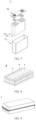
- FIG. 6 shows a prismatic secondary battery 5 as an example.
- the outer package may include a housing 51 and a cover plate 53.
- the housing 51 may include a bottom plate and a side plate connected to the bottom plate. The bottom plate and the side plate close in to form an accommodation cavity.
- the housing 51 is provided with an opening that communicates with the accommodation cavity.
- the cover plate 53 can cover the opening to close the accommodation cavity.
- the positive electrode plate, the negative electrode plate, and the separator may be wound or stacked to form the electrode assembly 52.
- the electrode assembly 52 is packaged in the accommodation cavity.
- the electrolytic solution serves a function of infiltration in the electrode assembly 52.
- the number of electrode assemblies 52 in a secondary battery 5 may be one or more, and may be selected by a person skilled in the art as actually required.
- the secondary battery may be assembled into a battery module.
- the battery module may include one or more secondary batteries, and the specific number of secondary batteries in a battery module may be selected by a person skilled in the art depending on the application scenario and capacity of the battery module.
- FIG. 8 shows a battery module 4 as an example.
- a plurality of secondary batteries 5 may be arranged sequentially along a length direction of the battery module 4.
- the secondary batteries may be arranged in any other manner.
- the plurality of secondary batteries 5 may be fixed by a fastener.
- the battery module 4 may further include a shell that provides an accommodation space.
- the plurality of secondary batteries 5 are accommodated in the accommodation space.
- the battery modules may be assembled into a battery pack.
- the battery pack may include one or more battery modules, and the specific number of battery modules in a battery pack may be selected by a person skilled in the art depending on practical applications and capacity of the battery pack.
- FIG. 9 and FIG. 10 show a battery pack 1 as an example.
- the battery pack 1 may contain a battery box and a plurality of battery modules 4 disposed in the battery box.
- the battery box includes an upper box 2 and a lower box 3.
- the upper box 2 fits the lower box 3 to form a closed space for accommodating the battery modules 4.
- the plurality of battery modules 4 may be arranged in the battery box in any manner.
- the electrical device includes at least one of the secondary battery, the battery module, or the battery pack according to this application.
- the secondary battery, the battery module, or the battery pack may be used as a power supply of the electrical device, or used as an energy storage unit of the electrical device.
- the electrical device may include, but without being limited to, a mobile device (such as a mobile phone or a laptop computer), an electric vehicle (such as a battery electric vehicle, a hybrid electric vehicle, a plug-in hybrid electric vehicle, an electric bicycle, an electric scooter, an electric golf cart, or an electric truck), an electric train, a ship, a satellite system, or an energy storage system.
- the secondary battery, the battery module, or the battery pack may be selected for the electrical device according to practical requirements of the electrical device.
- FIG. 11 shows an electrical device as an example.
- the electrical device may be a battery electric vehicle, a hybrid electric vehicle, a plug-in hybrid electric vehicle, or the like.
- a battery pack or a battery module may be employed.
- the device may be a mobile phone, a tablet computer, a notebook computer, or the like.
- the apparatus is generally required to be thin and light, and may have a secondary battery as a power supply.
- FIG. 1 is a schematic diagram of a production system of a metal foil for use in the following embodiments.
- the production system of the metal foil for use in the following embodiments includes: a first electrodeposition device 11, an etching device 15, a second electrodeposition device 12, and a plurality of rollers 130 configured to pull the metal foil.
- the first electrodeposition device 11 produces an electrodeposited metal foil (electrodeposited metal foil) by a first electrodeposition step.
- the first electrodeposition device 11 includes: a first electroplating bath 111, a first anode plate 112, and a first cathode roller 116.
- the first electroplating bath 111 contains an electroplating solution.
- the first anode plate 112 and the first cathode roller 116 are immersed in the electroplating solution.
- the first anode plate 112 and the first cathode roller 116 are disposed face to face.
- the raw metal foil 110 is generated between the first anode plate 112 and the first cathode roller 116.
- the first anode plate 112 and the first cathode roller 116 are made of titanium metal.
- the electroplating solution containing metal ions in the electrolytic bath 111 is electrolyzed under the action of the electric current between the first anode plate 112 and the first cathode roll 116, so that the metal ions are deposited on the surface of the first cathode roller 116 to form a metal deposition layer.
- the metal deposition layer is peeled off from the first cathode roller 116 to obtain the raw metal foil 110. Surface roughness varies between two sides of the raw metal foil 110. One side close to the first cathode roller 116 is relatively smooth, thereby referred to as a smooth side.
- the other side exhibits a convex-and-concave crystalline structure, and is relatively rough, thereby referred to as a rough side.
- the surface roughness varies greatly between the two sides of the raw metal foil 110, and the bonding force between each of the two surfaces and an active material is still insufficient.
- the raw metal foil 110 produced by the first electrodeposition device 11 is directly transferred to the etching device 15 under traction of the roller 130.
- the etching device 15 includes an etching bath 151.
- the etching bath 151 contains an etching solution.
- a roller 130 configured to pull the metal foil is further disposed in the etching bath.
- the raw metal foil 110 is etched by the etching solution, so as to obtain an etched metal foil 150.
- the surface roughness of both sides of the etched metal foil 150 is higher than that of the raw metal foil 110.
- the surface roughness is relatively close between two sides of the etched metal foil 150.
- the bonding force between each of two surfaces of an etched copper foil and an active material is still insufficient.
- the second electrodeposition device 12 includes: a second electroplating bath 121, a second anode plate A 122, a second anode plate B 128, and a second cathode roller 126.
- the second electroplating bath 121 contains an electroplating solution.
- the second cathode roller 126, the second anode plate A 122, and the second anode plate B 128 are immersed in the electroplating solution.
- the second anode plate A 122 faces one side of the metal foil
- the second anode plate B 128 faces the other side of the metal foil.
- the metal foil Under traction of the roller 130, the metal foil first passes between the second anode plate A 122 and the second cathode roller B 126, and then passes between the second cathode roller 126 and the second anode plate B 128, so as to obtain a multi-layered finished metal foil 120.
- the second cathode roller 126, the second anode plate A 122, and the second anode plate B 128 are made of titanium metal.
- a first metal layer and a second metal layer are deposited on two surfaces of the etched metal foil 150 respectively to obtain a multi-layered finished metal foil 120.
- the surface roughness of both sides of the finished metal foil 120 is lower than that of the etched metal foil 150.
- the surface roughness value is basically equal between two surfaces of the finished metal foil 120.
- FIG. 2 is a schematic diagram of a finished metal foil 120.
- the finished metal foil 120 includes the first metal layer 21, the metal base layer 22, and the second metal layer 23 that are stacked up.
- the metal base layer 22 is located between the first metal layer 21 and the second metal layer 23.
- a roughness Rz of a surface 221 that is of the metal base layer and that is oriented toward the first metal layer is ⁇ 1 ⁇ m.
- a roughness Rz of a surface 223 that is of the metal base layer and that is oriented toward the second metal layer is ⁇ 2 ⁇ m.
- a roughness Rz of a surface 230 that is of the second metal layer and that is oriented back from the metal base layer is ⁇ 2 ⁇ m, where ⁇ 2 ⁇ 3, and 0.5 ⁇ ⁇ 2 - ⁇ 2 ⁇ 1.5.
- the bonding force between the finished metal foil 120 and the active material is increased significantly unexpectedly.
- a possible reason for the improved bonding force may be that the metal layer derived from the second electrodeposition step inherits the rough contour of the surface of the etched copper foil 150 on the one hand, and modifies and improves the micro-morphology of the surface of the etched copper foil 150 on the other hand, thereby obtaining a surface particularly suitable for bonding with the active material.
- FIG. 3 shows an electrode according to some embodiments.
- the electrode includes a finished metal foil 120, a first active material layer 31, and a second active material layer 33 that are stacked up.
- the finished metal foil 120 is located between the first active material layer 31 and the second active material layer 33.
- the first active material layer 31 is stacked on the surface 210 that is of the first metal layer and that is oriented back from the metal base layer.
- the second active material layer 33 is stacked on the surface 230 that is of the second metal layer and that is oriented back from the metal base layer.
- the following describes how to produce a copper foil using the foregoing production system of the metal foil, and how to prepare an electrode using the copper foil as a current collector.
- the components of the electroplating solution of the first electroplating bath and the second electroplating bath are shown in the following table: Table 1 Component Concentration (g/L) Copper sulfate (CuSO 4 ) Concentration of Cu 2+ is 75 g/L Concentrated sulfuric acid (H 2 SO 4 , concentration 98%) Concentration of H 2 SO 4 is 180 g/L Chloride ions 0.05 g/L Gloss agent (manufacturer: Jiangsu Mengde New Materials Technology Co., Ltd.; designation: SPS&MPS; main component: a mixture of sodium 3-mercaptopropane sulfonate and sodium polydithiodipropane sulfonate) 0.31 g/L Planarization agent (manufacturer: Jiangsu Mengde New Materials Technology Co., Ltd.; designation: MDN; main component: polypeptide protein) 0.08 g/L Solvent Water pH value ⁇ 4
- Steps of preparing an electrolytic copper foil in an electrolytic copper foil preparation system are as follows:
- Table 3 shows technical parameters of the electrolytic copper foil preparation system, for example, first electrodeposition time, current density of the first electrodeposition step, etching time, second electrodeposition time, and current density of the second electrodeposition step.
- Comparative Embodiments 1 to 2 differ from Embodiment 1 in the technical parameters of the electrolytic copper foil preparation system, as detailed in Table 3 below.
- Comparative Embodiment 1 differs from Embodiment 1 in that the etching step is cancelled in Comparative Embodiment 1, the raw copper foil produced by the first electrodeposition device is directly conveyed to the second electrodeposition device, and a second electrodeposition step is performed on the etched copper foil, so that a first copper layer and a second copper layer are deposited on both sides of the etched copper foil to obtain the finished copper foil in Comparative Embodiment 1.
- Comparative Embodiment 1 Other steps and parameters (for example, the first electrodeposition step and the second electrodeposition step) in Comparative Embodiment 1 are the same as those in Embodiment 1.
- Comparative Embodiment 2 differs from Embodiment 1 in:
- Comparative Embodiment 2 Other steps and parameters (for example, the first electrodeposition step and the etching step) in Comparative Embodiment 2 are the same as those in Embodiment 1.
- the surface roughness Rz is measured with reference to the following standard: JIS B 0601,0031-1994 Surface Roughness and Drawing Indication of Surface Texture.
- the surface roughness parameters of the copper foils prepared in Embodiments 1 to 18 and intermediate products of each step are shown in Table 4.1 below.
- the surface roughness parameters of the copper foils prepared in Comparative Embodiments 1 to 2 and intermediate products of each step are shown in Table 4.2 below.
- the ratio R 1:2 represents a ratio of the first surface roughness Rz 1 to the second surface roughness Rz 2 .
- the difference ( ⁇ - ⁇ ) represents a difference between the first surface roughness Rz 1 of the etched copper foil and the first surface roughness Rz 1 of the finished copper foil, and a difference between the second surface roughness Rz 1 of the etched copper foil and the second surface roughness Rz 1 of the finished copper foil.
- the difference ( ⁇ - ⁇ ) represents a difference between the first surface roughness Rz 1 of the raw copper foil and the first surface roughness Rz 1 of the finished copper foil, and a difference between the second surface roughness Rz 1 of the raw copper foil and the second surface roughness Rz 1 of the finished copper foil.
- the copper foil in the embodiments and comparative embodiments as a current collector, and disposing an active material layer on both surfaces of the current collector in the following way: Coating a to-be-tested surface of a to-be-tested copper foil with a negative active material slurry of a lithium-ion battery, and performing drying and calendering to obtain an electrode plate.
- a compacted density of the electrode plate is 1.68 g/cm 3
- an areal density of coating is 134 g/cm 2 .
- the formula of the negative active material slurry of the lithium-ion battery is as follows: 96.8 wt% graphite, 0.4 wt% conductive carbon, 1.8 wt% styrene polybutadiene rubber, 1 wt% sodium carboxymethyl cellulose, and an appropriate amount of solvent (the solvent will volatilize in the subsequent drying process).
- FIG. 5 (a) to (d) show a flowchart of a peeling test.
- a steel sheet 510 is provided first. Dimensions of the steel sheet are 30 mm (width) ⁇ 100 mm (length).
- double-sided tape 520 is provided. The size of the double-sided tape 520 is 20 mm (width) ⁇ 30 mm (length). The double-sided tape 520 is affixed to the steel sheet 510. One widthwise edge of the double-sided tape 520 is aligned with one widthwise edge of the steel sheet 510.
- a to-be-tested electrode plate 530 is then provided.
- the dimensions of the to-be-tested electrode plate 530 are 30 mm (width) ⁇ 30 mm (length).
- the to-be-tested electrode plate 530 overlays the double-sided tape 520.
- the coated surface of the electrode plate 530 faces the double-sided tape 520, and one widthwise edge of the to-be-tested electrode plate 530 is aligned with one widthwise edge of the steel sheet 510. Because the length of the to-be-tested electrode plate 530 is greater than the length of the double-sided tape 520, a part of region of the to-be-tested electrode plate 520 is not bonded to the double-sided tape.
- the steel sheet 510 is fixed on a pedestal of a tensile testing machine.
- An end that is of the to-be-tested electrode plate 530 and that is not bonded to the double-sided tape is held with a clamp, and then the clamp is stretched toward the other end (in a direction indicated by the arrow).
- the direction of the stretching force is parallel to the strength direction of the steel sheet 510, and closely fits with the surface of the steel sheet 510.
- the electrode plate 530 is caused to be gradually peeled off from the steel sheet.
- the stretching speed of the clamp is 50 mm/min.
- the tensile force of the clamp is recorded. After the tensile force becomes steady, the electrode plate is further peeled by a length of 70 mm. An average tensile force under this peeling length is the bonding force.
- the room-temperature tensile strength and elongation rate of a copper foil are measured with reference to the following method: stamping a finished copper foil that has stood statically for 24 hours into a dumbbell shape (gauge length 50 mm, gauge width 3 mm), and then performing a tensile test and plotting a stress-strain curve.
- FIG. 4 shows an illustrative stress-strain curve, where the X-axis represents a strain value.
- a strain value 0.005 means that the elongation rate is 0.5%.
- the tensile strength corresponding to the elongation rate 0.5% is the curve stress value corresponding to the strain value of 0.005.
- an intersection between the straight line 402 and the stress-strain curve is a plastic deformation stress value corresponding to an elongation rate of 0.5% (yield strength corresponding to the elongation rate of 0.5%).
- the line segment 400 is a tangent line of the stress-strain curve at the strain of 0.
- Table 3 and Table 4 show the data of tensile strength, elongation rate, and bonding force of Embodiments 1 to 18 and Comparative Embodiments 1 to 4.
- Table 3 First electrodeposition step Etching Second electrodeposition step Metal base layer First metal layer Second metal layer Embodiment Time (h) Current density (A/dm 2 ) Time (min) Time (h) Current density (A/dm 2 ) Roughness ⁇ 1 ( ⁇ m) Roughness ⁇ 2 ( ⁇ m) Thickness d 0 ( ⁇ m) Grain size z (nm) Roughness ⁇ 1 ( ⁇ m) Thickness d 1 ( ⁇ m) Grain size a (nm) Roughness ⁇ 2 ( ⁇ m) Thickness d 2 ( ⁇ m) Grain size b (nm) 1 0.6 h 50 2 0.5 20 1.8 1.9 4.8 493 1.2 1.6 30 1.1 1.6 45 2 0.6 h 50 2.4 0.5 20 2.5 2.5 4.8 493 1.2 1.6 25 1.2 1.6
- the roughness Rz of the surface that is of the metal base layer and that is oriented toward the second metal layer is ⁇ 2 ⁇ m.
- the roughness Rz of the surface that is of the first metal layer and that is oriented back from the metal base layer is ⁇ 1 ⁇ m.
- the roughness Rz of the surface that is of the second metal layer and that is oriented back from the metal base layer is ⁇ 2 ⁇ m.
- the finished copper foil obtained in Embodiments 1 to 18 includes a first copper layer, a copper base layer, and a second copper layer.
- the copper base layer is located between the first copper layer and the second copper layer.
- the roughness Rz of a surface that is of the copper base layer and that is oriented toward the first copper layer is ⁇ 1 ⁇ m.
- the roughness Rz of a surface that is of the copper base layer and that is oriented toward the second copper layer is ⁇ 2 ⁇ m.
- the bonding force between the finished copper foil prepared in Embodiments 1 to 18 and the active material is increased unexpectedly, and is up to 12 to 17 N.
- the bonding force on two sides of the copper foil is very homogeneous.
- the copper foil is especially suitable for being coated on both sides.
- the bonding force between the copper foil in Comparative Embodiment 1 and the active material is approximately 10 N.
- the bonding force between the copper foil in Comparative Embodiment 2 and the active material is approximately 1 N to 3 N.
- Comparative Embodiment 3 implements just the first electrodeposition step and the etching step, without performing the second electrodeposition step.
- the copper foil in Comparative Embodiment 2 is not layered, and the surface roughness values on the two sides of the copper foil are 2.5 ⁇ m and 2.5 ⁇ m, respectively.
- the bonding force between the copper foil and the active material is as low as 1 N to 2 N.
- Comparative Embodiment 4 omits the etching step, and the raw copper foil produced by the first electrodeposition step is directly subjected to a second electrodeposition step, so that a first copper layer and a second copper layer are deposited on both sides of the raw copper foil.
- the first copper layer and the second copper layer achieve the following advantages: on the one hand, the two copper layers inherit the rough contour of the surface of the copper base layer; on the other hand, the two copper layers modify and improve a micro-morphology of the surface of the copper base layer, thereby ultimately producing a surface suitable for bonding with the active material, and exhibiting an unexpected force of bonding with the active material.
- the copper foils in Embodiments 1 to 18 also perform well in terms of tensile strength and elongation rate.
- the average grain size on a cross-section of a copper foil may be determined with reference to the following standard: GBT 38532-2020 Microbeam Analysis Electron Backscatter Diffraction Measurement of Average Grain Size. Table 4 shows the test results.
- the cross-section of the copper foil in Embodiments 1 to 18 is divided into three layered regions: a first layered region, a core layered region, and a second layered region.
- the first layered region, the core layered region, and the second layered region are substantially parallel to the surface of the metal foil.
- the core layered region is located between the first layered region and the second layered region.
- the first layered region, the core layered region, and the second layered region correspond to the cross sections of the first copper layer, the copper base layer, and the second copper layer, respectively.
- Embodiments 1 to 18 the use of a copper base layer with a relatively large grain size (for example, 114 to 925 nm) is conducive to production. In contrast to a small grain size, producing a copper deposition layer with a large grain size is more efficient and cost-effective, without sacrificing the performance of the finished copper foil.
- a copper base layer with a relatively small grain size for example, 10 to 100 nm
- the copper foil can still achieve an improved bonding force.
- the use of the first copper layer and second copper layer with a relatively small grain size is conducive to improving the bonding force of the copper foil.
- the copper deposition layer with a small grain size inherits the rough contour of the copper base layer on the one hand, and improves and modifies the micro-morphology of the surface of the copper base layer on the other hand, thereby forming a surface suitable for bonding with the active material.
- the cross-section of the copper foil in Comparative Embodiment 3 exhibits no obvious partitioning interface.
- the average grain size of the cross-section in Comparative Embodiment 2 is tested for different regions in the same way as the layered region structure in Embodiment 1, the results show that the grain size is uniformly 493 nm for all regions.
Landscapes
- Chemical & Material Sciences (AREA)
- Engineering & Computer Science (AREA)
- Electrochemistry (AREA)
- Materials Engineering (AREA)
- Chemical Kinetics & Catalysis (AREA)
- Organic Chemistry (AREA)
- Metallurgy (AREA)
- General Chemical & Material Sciences (AREA)
- Composite Materials (AREA)
- Crystallography & Structural Chemistry (AREA)
- Life Sciences & Earth Sciences (AREA)
- Sustainable Development (AREA)
- Sustainable Energy (AREA)
- Power Engineering (AREA)
- Transportation (AREA)
- Mechanical Engineering (AREA)
- Cell Electrode Carriers And Collectors (AREA)
Abstract
Description
- This application relates to the technical field of lithium batteries, and in particular, to a metal foil and a preparation method thereof, a current collector, an electrode, a battery, and an electrical device.
- In recent years, the application scope of lithium-ion batteries has been expanded. The lithium-ion batteries are widely used in energy storage power systems such as hydro, thermal, wind, and solar power stations, and many other fields such as electric tools, electric bicycles, electric motorcycles, and electric vehicles, military equipment, and aerospace. The great development of the lithium-ion batteries gives rise to higher requirements on the energy density, cycle performance, safety performance, and other performance of the batteries.
- In a lithium-ion battery, the current collector is a carrier that carries an electrode active material. The active material of the lithium-ion battery is prone to some expansion and shrinkage in charge-and-discharge cycles. The repeated volume changes are prone to cause peel-off of the active material from the current collector. Therefore, improving a bonding force between the active material and the current collector is conducive to achieving stable battery performance.
- This application is targeted at the foregoing problems, and aims to provide a current collector characterized by an improved bonding force between the current collector and an active material.
- To achieve the foregoing objective, a first aspect of this application provides a metal foil, where the metal foil includes a first metal layer and a metal base layer that are stacked up. A roughness Rz of a surface that is of the metal base layer and that is oriented toward the first metal layer is α1 µm, a roughness Rz of a surface that is of the first metal layer and that is oriented back from the metal base layer is β1 µm, α1 = 1.8 to 2.9, and β1 = 1 to 1.4. The metal foil possesses an improved force of bonding with the active material.
- In any embodiment, the metal foil includes the first metal layer, the metal base layer, and a second metal layer that are stacked up. The metal base layer is located between the first metal layer and the second metal layer. A roughness Rz of a surface that is of the metal base layer and that is oriented toward the second metal layer is α2 µm, a roughness Rz of a surface that is of the second metal layer and that is oriented back from the metal base layer is β2 µm, α2 = 1.8 to 2.9, and β2 = 1 to 1.4. Both sides of the metal foil possess an improved force of bonding with the active material.
- In any embodiment, a ratio of α1 to α2 is 0.9 to 1.1, and optionally 1. Both sides of the metal foil possess homogeneous structures and properties.
- In any embodiment, a ratio of β1 to β2 is 0.9 to 1.1, and optionally 1. Both sides of the metal foil possess homogeneous structures and properties.
- In any embodiment, α1 = 2.4 to 2.6; and β1 = 1.1 to 1.3. The metal foil possesses an improved force of bonding with the active material.
- In any embodiment, α2 = 2.4 to 2.6; and β2 = 1.1 to 1.3. The metal foil possesses an improved force of bonding with the active material.
- In any embodiment, an average grain size a of the first metal layer and an average grain size z of the metal base layer satisfy: a: z = 1: (3 to 35), for example, a: z = 1: (5.4 to 32.9). The metal foil is cost-efficient and of relatively high performance.
- In any embodiment, an average grain size b of the second metal layer and an average grain size z of the metal base layer satisfy: a: z = 1: (3 to 35), for example, b: z = 1: (3.5 to 35.2). The metal foil is cost-efficient and of relatively high performance.
- In any embodiment, measured in nm, an average grain size a of the first metal layer satisfies 10 ≤ a ≤ 70; measured in nm, an average grain size z of the metal base layer satisfies 100 ≤ z ≤ 1000; and measured in nm, an average grain size of a second metal layer satisfies 10 ≤ b ≤ 70. The metal foil is cost-efficient and possesses good mechanical properties.
- In any embodiment, measured in nm, an average grain size a of the first metal layer satisfies 15 ≤ a ≤ 57; measured in nm, an average grain size z of the metal base layer satisfies 114 < z ≤ 925; and measured in nm, an average grain size of a second metal layer satisfies 14 ≤ b ≤ 69. The metal foil is cost-efficient and possesses good mechanical properties.
- In any embodiment, a thickness of the first metal layer is 1.2 to 2.0 µm, a thickness of the metal base layer is 4.4 to 5.2 µm, and a thickness of a second metal layer is 1.2 to 2.0 µm. The metal foil possesses an appropriate thickness and good mechanical properties, and is suitable for use as a current collector of a battery.
- In any embodiment, a total thickness of the metal foil is 7.2 to 8.4 µm. The metal foil possesses an appropriate thickness and good mechanical properties, and is suitable for use as a current collector of a battery.
- In any embodiment, a tensile strength of the metal foil is at least 34 kg/mm2, and optionally 34 to 40 kg/mm2. The metal foil possesses improved mechanical properties, and is suitable for use as a current collector of a battery.
- In any embodiment, an elongation rate of the metal foil is at least 3.2%, and optionally 3.2% to 3.8%. The metal foil possesses improved mechanical properties, and is suitable for use as a current collector of a battery.
- In any embodiment, a bonding force of the metal foil is at least 12 N/m2, and optionally 12 to 17 N/m2. The metal foil possesses an improved bonding force, and is suitable for use as a current collector of a battery.
- In any embodiment, the first metal layer, the metal base layer, and a second metal layer each are independently made of copper, aluminum, nickel, titanium, silver, or an alloy of any one thereof. The metal foil possesses stable chemical properties, and is suitable for use as a current collector of a battery.
- In any embodiment, the first metal layer, the metal base layer, and the second metal layer are all made of copper or a copper alloy. The metal foil is suitable for use as a current collector of a battery, especially a negative current collector.
- A second aspect of this application provides a method for preparing a metal foil, characterized in that the method includes the following steps:
- S1: providing a raw metal foil;
- S2: roughening one surface of the raw metal foil to form a first roughened surface on one side of the raw metal foil, where a roughness Rz of the first roughened surface is α1 µm, and α1 = 1.8 to 2.9; and
- S3: depositing a first metal layer on the first roughened surface.
- A roughness Rz of a surface that is of the first metal layer and that is oriented back from the first roughened surface is β1 µm, and β1 = 1 to 1.4. The metal foil prepared from this method possesses an improved bonding force.
- A third aspect of this application provides a method for preparing a metal foil, characterized in that the method includes the following steps:
- S1: providing a raw metal foil;
- S2: roughening both surfaces of the raw metal foil to form a first roughened surface and a second roughened surface on two sides of the raw metal foil respectively, where a roughness Rz of the first roughened surface is α1 µm, and a roughness Rz of the second roughened surface is α2 µm, α1 = 1.8 to 2.9, and α2 = 1.8 to 2.9; and
- S3: depositing a first metal layer on the first roughened surface, and depositing a second metal layer on the second roughened surface.
- A roughness Rz of a surface that is of the first metal layer and that is oriented back from the first roughened surface is β1 µm, and β1 = 1 to 1.4.
- A roughness Rz of a surface that is of the second metal layer and that is oriented back from the second roughened surface is β2 µm, and β2 = 1 to 1.4. The metal foil prepared from this method possesses an improved bonding force.
- In any embodiment, in step S2, the roughness of both surfaces of the raw metal foil is achieved by one or more of the following processing methods: chemical etching, electrochemical etching, or a combination thereof. The metal foil prepared from this method possesses an improved bonding force.
- In any embodiment, in step S3, the raw metal foil is prepared by a first electrodeposition step, both surfaces of the raw metal foil are roughened by chemical etching, and the first metal layer and a second metal layer are deposited on the first roughened surface and a second roughened surface respectively by a second electrodeposition step. The metal foil prepared from this method possesses an improved bonding force.
- In any embodiment, in step S3, the first electrodeposition step is implemented in a first electroplating solution, and the first electroplating solution includes the following components:
Cu2+ 50 g/L to 100 g/L; H2SO4 150 g/L to 250 g/L; Cl- 0.03 g/L to 0.08 g/L; - Optionally, the first electroplating solution further contains a gloss agent, a planarization agent, or a combination thereof.
- Optionally, a pH value of the first electroplating solution is less than 4. The metal foil prepared from this method possesses an improved bonding force.
- In any embodiment, in step S2, chemical etching is implemented in an etching solution, and the etching solution includes the following components:
- 1-butyl-3-methylimidazolium chloride 0.5 g/L to 5 g/L; and
- copper sulfate 50 g/L to 250 g/L. The metal foil prepared from this method possesses an improved bonding force.
- In any embodiment, a second electrodeposition step is implemented in a second electroplating solution, and the second electroplating solution includes the following components:
Cu2+ 50 g/L to 100 g/L; H2SO4 150 g/L to 250 g/L; and Cl- 0.03 g/L to 0.08 g/L. - The metal foil prepared from this method possesses an improved bonding force.
- In any embodiment, the second electroplating solution further contains an electroplating additive such as a gloss agent, a planarization agent, or a combination thereof; and
In any embodiment, a pH value of the first electroplating solution is less than 4. - In any embodiment, a current density in a first electrodeposition step is C1 A/dm2, and a current density in a second electrodeposition step is C2 A/dm2, and therefore, 1.25 ≤ C1: C2 <_ 5.
- Optionally, C1 is 25 to 100, and C2 is 10 to 40. The metal foil prepared from this method possesses an improved bonding force.
- A fourth aspect of this application provides a current collector, including the metal foil according to any one of the foregoing aspects, or the metal foil prepared by the method according to any one of the foregoing aspects.
- A fifth aspect of this application provides a battery, including the current collector according to any one of the foregoing aspects.
- A sixth aspect of this application provides an electrical device. The electrical device includes the battery according to any one of the foregoing aspects, and the battery is configured to provide electrical energy.
- One or more embodiments of the present disclosure achieve one or more of the following benefits:
- (1) The metal foil is used as a current collector, the bonding force between the current collector and the active material is improved, and then the stability of an electrode based on the current collector is improved, and in turn, comprehensive performance based on the electrode is improved.
- (2) The metal foil in some embodiments possesses improved strength and toughness.
- (3) The metal foil in some embodiments is easy to produce, and superior in cost-efficiency, production efficiency, and performance.
-
-
FIG. 1 is a schematic diagram of a production system of a metal foil according to some embodiments of this application; -
FIG. 2 is a schematic diagram of a metal foil according to some embodiments of this application; -
FIG. 3 is a schematic diagram of an electrode according to some embodiments of this application; -
FIG. 4 shows an illustrative stress-strain curve. -
FIG. 5 (a) to (d) show a flowchart of a peeling test. -
FIG. 6 is a schematic diagram of a secondary battery according to an embodiment of this application; -
FIG. 7 is an exploded view of a secondary battery shown inFIG. 6 according to an embodiment of this application; -
FIG. 8 is a schematic diagram of a battery module according to an embodiment of this application; -
FIG. 9 is a schematic diagram of a battery pack according to an embodiment of this application; -
FIG. 10 is an exploded view of the battery pack shown inFIG. 9 according to an embodiment of this application; and -
FIG. 11 is a schematic diagram of an electrical device that uses a secondary battery as a power supply according to an embodiment of this application. - Reference numerals:
-
first electrodeposition device 11;first electroplating bath 111;first anode plate 112;first cathode roller 116; etchingdevice 15; etchingbath 151;second electrodeposition device 12;second electroplating bath 121; secondanode plate A 122; secondanode plate B 128;second cathode roller 126;roller 130;raw metal foil 110; etchedmetal foil 150;
finished metal foil 120; -
first metal layer 21;metal base layer 22;second metal layer 23;surface 221 that is of the metal base layer and that is oriented toward the first metal layer;surface 210 that is of the first metal layer and that is oriented back from the metal base layer;surface 223 that is of the metal base layer and that is oriented toward the second metal layer;surface 230 that is of the second metal layer and that is oriented back from the metal base layer; firstactive material layer 31; secondactive material layer 33; and -
battery pack 1;upper box 2;lower box 3;battery module 4;secondary battery 5;housing 51;electrode assembly 52;cap assembly 53. - The following describes in detail a metal foil and a preparation method thereof, an electrode plate, a secondary battery, a battery module, a battery pack, and an electrical device according to this application with due reference to drawings. However, unnecessary details may be omitted in some cases. For example, a detailed description of a well-known matter or repeated description of a substantially identical structure may be omitted. That is intended to prevent the following descriptions from becoming unnecessarily long, and to facilitate understanding by a person skilled in the art. In addition, the drawings and the following descriptions are intended for a person skilled in the art to thoroughly understand this application, but not intended to limit the subject-matter set forth in the claims.
- A "range" disclosed herein is defined in the form of a lower limit and an upper limit. A given range is defined by selecting a lower limit and an upper limit. The selected lower and upper limits define the boundaries of the given range. A range so defined may be inclusive or exclusive of the end values, and may be arbitrarily combined. That is, any lower limit may be combined with any upper limit to form a range. For example, if a range of 60 to 120 and a range of 80 to 110 are listed for a given parameter, it is expectable that such ranges may be understood as 60 to 110 and 80 to 120. In addition, if lower-
limit values limit values - Unless otherwise expressly specified herein, all embodiments and optional embodiments hereof may be combined with each other to form a new technical solution.
- Unless otherwise expressly specified herein, all technical features and optional technical features hereof may be combined with each other to form a new technical solution.
- Unless otherwise expressly specified herein, all the steps described herein may be performed sequentially or randomly, and optionally, performed sequentially. For example, that the method includes steps (a) and (b) indicates that the method may include steps (a) and (b) performed sequentially, or steps (b) and (a) performed sequentially. For example, that the method may further include step (c) indicates that step (c) may be added into the method in any order. For example, the method may include steps (a), (b), and (c), or may include steps (a), (c), and (b), or may include steps (c), (a), and (b), and so on.
- Unless otherwise expressly specified herein, "include" and "comprise" mentioned herein mean open-ended inclusion, and may also mean closed-ended inclusion. For example, the terms "include" and "comprise" may mean inclusion of other items not listed, or inclusion of only the listed items.
- Unless otherwise expressly specified herein, the term "or" is inclusive. For example, the phrase "A or B" means "A alone, B alone, or both A and B." More specifically, the condition "A or B" is satisfied by any of the following: A is true (or existent) and B is false (or absent); A is false (or absent) and B is true (or existent); or, both A and B are true (or existent).
- To achieve the foregoing objective, a first aspect of this application provides a metal foil, where the metal foil includes a first metal layer and a metal base layer that are stacked up. A roughness Rz of a surface that is of the metal base layer and that is oriented toward the first metal layer is α1 µm, a roughness Rz of a surface that is of the first metal layer and that is oriented back from the metal base layer is β1 µm, α1 = 1.8 to 2.9 (for example, 1.8 to 1.9, 1.9 to 2, 2 to 2.1, 2.1 to 2.2, 2.2 to 2.3, 2.3 to 2.4, 2.4 to 2.5, 2.5 to 2.6, 2.6 to 2.7, 2.7 to 2.8, or 2.8 to 2.9), and β1 = 1 to 1.4 (for example, 1 to 1.1, 1.1 to 1.2, 1.2 to 1.3, or 1.3 to 1.4). The metal foil possesses an improved force of bonding with the active material.
- Although the underlying mechanism remains unclear, the applicant hereof unexpectedly finds that, in this application, by using a relatively high roughness of the surface that is of the metal base layer and that is oriented toward the first metal layer (for example, letting the roughness be greater than or equal to 3 µm), despite the fact that the bonding force between an excessively rough surface and an active material is not high, after the surface is overlaid with the first metal layer, the first metal layer achieves the following advantages: on the one hand, the first metal layer inherits the rough contour of the surface of the metal base layer; on the other hand, the first metal layer modifies and improves a micro-morphology of the surface of the metal base layer, thereby ultimately producing a surface suitable for bonding with the active material, and exhibiting an unexpected force of bonding with the active material.
- In any embodiment, the term "stacked" means that two layers fit with each other directly or indirectly. In this context, the term "directly" means that no intervening layer, for example, exists between two layers, and the term "indirectly" means that an intervening layer exists between the two layers.
- In any embodiment, the metal foil includes the first metal layer, the metal base layer, and a second metal layer that are stacked. The metal base layer is located between the first metal layer and the second metal layer. A roughness Rz of a surface that is of the metal base layer and that is oriented toward the second metal layer is α2 µm, a roughness Rz of a surface that is of the second metal layer and that is oriented back from the metal base layer is β2 µm, α1 = 1.8 to 2.9, (for example, 1.8 to 1.9, 1.9 to 2, 2 to 2.1, 2.1 to 2.2, 2.2 to 2.3, 2.3 to 2.4, 2.4 to 2.5, 2.5 to 2.6, 2.6 to 2.7, 2.7 to 2.8, or 2.8 to 2.9), and β1 = 1 to 1.4 (for example, 1 to 1.1, 1.1 to 1.2, 1.2 to 1.3, or 1.3 to 1.4). Both sides of the metal foil possess an improved force of bonding with the active material.
- Although the underlying mechanism remains unclear, the applicant hereof unexpectedly finds that, in this application, by using a relatively high roughness of the surfaces that are of the metal base layer and that are oriented toward the first metal layer and the second metal layer respectively (for example, letting the roughness be greater than or equal to 3 µm), despite the fact that the bonding force between an excessively rough surface and an active material is not high, after the surface is overlaid with the first metal layer or the second metal layer, the first metal layer and the second metal layer achieve the following advantages: on the one hand, the two metal layers inherit the rough contour of the surface of the metal base layer; on the other hand, the two metal layers modify and improve a micro-morphology of the surface of the metal base layer, thereby ultimately producing a surface suitable for bonding with the active material, and exhibiting an unexpected force of bonding with the active material.
- In any embodiment, a ratio of α1 to α2 is 0.9 to 11 (for example, 1). Both sides of the metal foil possess homogeneous structures and properties, thereby being symmetrical, and achieving improved performance when applied to a current collector of a battery.
- In any embodiment, a ratio of β1 to β2 is 0.9 to 1.1 (for example, 1). Both sides of the metal foil possess homogeneous structures and properties, thereby being symmetrical, and achieving improved performance when applied to a current collector of a battery.
- In any embodiment, α1 = 2.4 to 2.6; and β1 = 1.1 to 1.3. The metal foil possesses an improved force of bonding with the active material.
- In any embodiment, α2 = 2.4 to 2.6; and β2 = 1.1 to 1.3. The metal foil possesses an improved force of bonding with the active material.
- In any embodiment, an average grain size a of the first metal layer and an average grain size z of the metal base layer satisfy: a: z = 1: (3 to 35) (for example, 3 to 10, 10 to 20, 20 to 30, or 30 to 35), and b: z = 1: (3 to 35) (for example, 3 to 10, 10 to 20, 20 to 30, or 30 to 35). The metal foil is cost-efficient and of relatively high performance. When such a metal foil is used as a current collector, the bonding force between the current collector and the active material is further improved. The use of a metal base layer with a relatively large grain size is conducive to production. In contrast to a small grain size, producing a metal deposition layer with a large grain size is more efficient and cost-effective, without sacrificing the performance of the finished metal foil.
- In any embodiment, measured in nm, an average grain size a of the first metal layer satisfies 10 ≤ a ≤ 70 (for example, 10 to 20, 20 to 30, 30 to 40, 40 to 50, 50 to 60, or 60 to 70); measured in nm, an average grain size z of the metal base layer satisfies 100 ≤ z ≤ 1000 (for example, 10 to 20, 20 to 30, 30 to 40, 40 to 50, 50 to 60, 60 to 70, 70 to 80, 80 to 90, or 90 to 100); and, measured in nm, an average grain size of a second metal layer satisfies 10 ≤ b ≤ 70 (for example, 10 to 20, 20 to 30, 30 to 40, 40 to 50, 50 to 60, or 60 to 70). The metal foil possesses an improved force of bonding with the active material.
- In any embodiment, measured in nm, the average grain size a of the first metal layer satisfies 15 ≤ a ≤ 57; measured in nm, the average grain size z of the metal base layer satisfies 114 ≤ z ≤ 925; and measured in nm, the average grain size of a second metal layer satisfies 14 ≤ b ≤ 69. The metal foil possesses an improved force of bonding with the active material.
- In any embodiment, a thickness of the first metal layer is 1.2 to 2.0 µm, a thickness of the metal base layer is 4.4 to 5.2 µm, and a thickness of a second metal layer is 1.2 to 2.0 µm. The metal foil possesses a moderate thickness and good mechanical properties, and is suitable for use as a current collector of a battery.
- In any embodiment, a total thickness of the metal foil is 7.2 to 8.4 µm. The metal foil possesses an appropriate thickness and good mechanical properties, and is suitable for use as a current collector of a battery.
- In any embodiment, a tensile strength of the metal foil is at least 34 kg/mm2, and optionally 34 to 40 kg/mm2. The metal foil possesses improved mechanical properties, and is suitable for use as a current collector of a battery.
- In any embodiment, an elongation rate of the metal foil is at least 3.2%, and optionally 3.2% to 3.8%. The metal foil possesses improved mechanical properties, and is suitable for use as a current collector of a battery.
- In any embodiment, a bonding force of the metal foil is at least 12 N/m2, and optionally 12 to 17 N/m2. The metal foil possesses an improved bonding force, and is suitable for use as a current collector of a battery.
- In any embodiment, the first metal layer, the metal base layer, and a second metal layer each are independently made of copper, aluminum, nickel, titanium, silver, or an alloy of any one thereof. The metal foil possesses stable chemical properties, and is suitable for use as a current collector of a battery.
- In any embodiment, the first metal layer, the metal base layer, and the second metal layer are all made of copper or a copper alloy. The metal foil is well adaptable to a negative electrode material of the battery, and is suitable for use as a current collector of a battery, especially a negative current collector.
- A second aspect of this application provides a method for preparing a metal foil, characterized in that the method includes the following steps:
- S1: providing a raw metal foil;
- S2: roughening one surface of the raw metal foil to form a first roughened surface on one side of the raw metal foil, where a roughness Rz of the first roughened surface is α1 µm, and α1 = 1.8 to 2.9; and
- S3: depositing a first metal layer on the first roughened surface.
- A roughness Rz of a surface that is of the first metal layer and that is oriented back from the first roughened surface is β1 µm, and β1 = 1 to 1.4. The metal foil prepared from this method possesses an improved bonding force.
- The metal foil prepared from this method possesses an improved bonding force.
- A third aspect of this application provides a method for preparing a metal foil, characterized in that the method includes the following steps:
- S1: providing a raw metal foil;
- S2: roughening both surfaces of the raw metal foil to form a first roughened surface and a second roughened surface on two sides of the raw metal foil respectively, where a roughness Rz of the first roughened surface is α1 µm, and a roughness Rz of the second roughened surface is α2 µm, α1 = 1.8 to 2.9, and α2 = 1.8 to 2.9; and
- S3: depositing a first metal layer on the first roughened surface, and depositing a second metal layer on the second roughened surface.
- A roughness Rz of a surface that is of the first metal layer and that is oriented back from the first roughened surface is β1 µm, and β1 = 1 to 1.4.
- A roughness Rz of a surface that is of the second metal layer and that is oriented back from the second roughened surface is β2 µm, and β2 = 1 to 1.4. Both surfaces of the metal foil prepared from this method possess an improved bonding force.
- In any embodiment, in step S2, the roughness of both surfaces of the raw metal foil is achieved by one or more of the following processing methods: chemical etching, electrochemical etching, or a combination thereof. The metal foil prepared from this method possesses an improved bonding force.
- In any embodiment, in step S3, the raw metal foil is prepared by a first electrodeposition step, both surfaces of the raw metal foil are roughened by chemical etching, and the first metal layer and a second metal layer are deposited on the first roughened surface and a second roughened surface respectively by a second electrodeposition step. The metal foil prepared from this method possesses an improved bonding force.
- In any embodiment, the first metal layer and/or the second metal layer is deposited on the surface of the metal base layer by one or more of the following methods: for example, sputtering, electroplating, molding, chemical vapor deposition (Chemical Vapor Deposition, CVD), physical vapor deposition (Physical Vapor Deposition, PVD), evaporation, hybrid physical-chemical vapor deposition (Hybrid Physical-Chemical Vapor Deposition, HPCVD), plasma enhanced chemical vapor deposition (Plasma Enhanced Chemical Vapor Deposition, PECVD), low pressure chemical vapor deposition (Low Pressure Chemical Vapor Deposition, LPCVD), and the like.
- In any embodiment, the first metal layer and/or the second metal layer are stacked on the surface of the metal base layer separately by means of electrodeposition.
- The term "electrodeposition" means a process by which electrons are donated to ionic metal to form a non-ionic coating layer on a conductive surface. A corresponding system may include a chemical solution of a metal in ionic form, an anode (that is, an electrode that can be negatively charged corresponding to a metal to be plated), and a cathode (that is, a positively charged electrode that donates electrons to produce a non-ionic metal film on the conductive surface). For electroplating with or electrodepositing a metal such as copper, a water-based solution containing the metal to be deposited as ions (especially, a dissolved metal salt) may be used. An electrical field between the anode and cathode can force positively charged metal ions to move to the cathode and deposit on the cathode surface.
- The terms "electrodeposition" and "electroplating" are used interchangeably.
- In any embodiment, in step S2, the roughness of both surfaces of the raw metal foil is achieved by one or more of the following processing methods: chemical etching, electrochemical etching, or a combination thereof. The metal foil prepared from this method possesses an improved bonding force.
- In any embodiment, the term "chemical etching" means a process by which at least a part of materials is removed from the surface of the metal foil by a chemical etching solution to create a specific texture and/or roughness.
- In any embodiment, the term "electrochemical etching" means a process by which at least a part of materials is removed from the surface of the metal foil under the action of an electric current by using the metal foil as an anode in an electrolytic solution, so as to create a specific texture and/or roughness.
- In any embodiment, in step S3, the raw metal foil is prepared by a first electrodeposition step, both surfaces of the raw metal foil are roughened by chemical etching, and the first metal layer and a second metal layer are deposited on the first roughened surface and a second roughened surface respectively by a second electrodeposition step. The metal foil prepared from this method possesses an improved bonding force.
- In any embodiment, in step S3, the first electrodeposition step is implemented in a first electroplating solution, and the first electroplating solution includes the following components:
- Cu2+ 50 g/L to 100 g/L, for example, 60 g/L to 70 g/L, 70 g/L to 80 g/L, 80 g/L to 90 g/L, or 90 g/L to 100 g/L;
- H2SO4 150 g/L to 250 g/L, for example, 150 g/L to 170 g/L, 170 g/L to 190 g/L, 190 g/L to 210 g/L, 210 g/L to 230 g/L, or 230 g/L to 250 g/L; and
- Cl- 0.03 g/L to 0.08 g/L, for example, 0.03 g/L to 0.05 g/L, 0.05 g/L to 0.07 g/L, or 0.07 g/L to 0.08 g/L.
- In any embodiment, the first electroplating solution further contains a gloss agent, a planarization agent, or a combination thereof. The metal foil prepared from this method possesses an improved bonding force.
- In any embodiment, a pH value of the first electroplating solution is less than 4. The metal foil prepared from this method possesses an improved bonding force.
- In any embodiment, in step S2, chemical etching is implemented in an etching solution, and the etching solution includes the following components:
- 1-butyl-3-methylimidazolium chloride 0.5 g/L to 5 g/L, for example, 0.5 g/L to 1 g/L, 1 g/L to 2 g/L, 2 g/L to 3 g/L, 3 g/L to 4g/L, or 4 g/L to 5 g/L; and
- copper sulfate 50 g/L to 250 g/L.
- The metal foil prepared from this method possesses an improved bonding force.
- In any embodiment, a second electrodeposition step is implemented in a second electroplating solution, and the second electroplating solution includes the following components:
- Cu2+ 50 g/L to 100 g/L, for example, 60 g/L to 70 g/L, 70 g/L to 80 g/L, 80 g/L to 90 g/L, or 90 g/L to 100 g/L;
- H2SO4 150 g/L to 250 g/L, for example, 150 g/L to 170 g/L, 170 g/L to 190 g/L, 190 g/L to 210 g/L, 210 g/L to 230 g/L, or 230 g/L to 250 g/L; and
- Cl- 0.03 g/L to 0.08 g/L, for example, 0.03 g/L to 0.05 g/L, 0.05 g/L to 0.07 g/L, or 0.07 g/L to 0.08 g/L.
- The metal foil prepared from this method possesses an improved bonding force.
- In any embodiment, the second electroplating solution further contains an electroplating additive such as a gloss agent, a planarization agent, or a combination thereof.
- In any embodiment, a pH value of the first electroplating solution is less than 4.
- In any embodiment, a current density in a first electrodeposition step is C1 A/dm2, and a current density in a second electrodeposition step is C2 A/dm2, and therefore, 1.25 ≤ C1: C2 < 5. The metal foil prepared from this method possesses an improved bonding force.
- In any embodiment, C1 is 25 to 100 (for example, 30 to 40, 40 to 50, 50 to 60, 60 to 70, 70 to 80, 80 to 90, or 90 to 100), and C2 is 10 to 40 (for example, 10 to 15, 15 to 25, 25 to 35, or 35 to 40). The metal foil prepared from this method possesses an improved bonding force.
- A fourth aspect of this application provides a current collector, including the metal foil according to any one of the foregoing aspects, or the metal foil prepared by the method according to any one of the foregoing aspects.
- A fifth aspect of this application provides a battery, including the current collector according to any one of the foregoing aspects.
- A sixth aspect of this application provides an electrical device. The electrical device includes the battery according to any one of the foregoing aspects, and the battery is configured to provide electrical energy.
- In addition, a secondary battery, a battery module, a battery pack, and an electrical device according to this application are described below in detail with due reference to drawings.
- In an embodiment of this application, a secondary battery is provided.
- Generally, the secondary battery includes a positive electrode plate, a negative electrode plate, an electrolyte, and a separator. In a charge-and-discharge cycle of the battery, active ions are shuttled between the positive electrode plate and the negative electrode plate by intercalation and deintercalation. The electrolyte serves to conduct ions between the positive electrode plate and the negative electrode plate. Located between the positive electrode plate and the negative electrode plate, the separator mainly serves to prevent a short circuit between the positive electrode plate and the negative electrode plate, and is penetrable to ions.
- The positive electrode plate includes a positive current collector and a positive film layer that overlays at least one surface of the positive current collector. The positive film layer includes a positive active material according to the first aspect of this application.
- As an example, the positive current collector includes two surfaces opposite to each other in a thickness direction thereof. The positive film layer is disposed on either or both of the two opposite surfaces of the positive current collector.
- In some embodiments, the positive current collector may be a metal foil or a composite current collector. For example, the metal foil may be an aluminum foil. The composite current collector may include a polymer material base layer and a metal layer formed on at least one surface of the polymer material base layer. The composite current collector may be formed by overlaying a polymer material substrate with a metal material (for example, aluminum, aluminum alloy, nickel, nickel alloy, titanium, titanium alloy, silver, and silver alloy). The polymer material substrate may be, for example, polypropylene (PP), polyethylene terephthalate (PET), polybutylene terephthalate (PBT), polystyrene (PS), or polyethylene (PE).
- In some embodiments, the positive active material may be a positive active material that is well known in the art for use in a battery. As an example, the positive active material may include at least one of the following materials: olivine-structured lithium-containing phosphate, lithium transition metal oxide, and a modified compound thereof. However, this application is not limited to such materials, and other conventional materials usable as a positive active material of a battery may be used instead. One of the positive active materials may be used alone, or at least two thereof may be combined and used together. Examples of the lithium transition metal oxide may include, but are not limited to, at least one of lithium cobalt oxide (such as LiCoO2), lithium nickel oxide (such as LiNiO2), lithium manganese oxide (such as LiMnO2, and LiMn2O4), lithium nickel cobalt oxide, lithium manganese cobalt oxide, lithium nickel manganese oxide, lithium nickel cobalt manganese oxide (such as LiNi1/3Co1/3Mn1/3O2 (briefly referred to as NCM333), LiNi0.5Co0.2Mn0.3O2 (briefly referred to as NCM523), LiNi0.5Co0.25Mn0.25O2 (briefly referred to as NCM211), LiNi0.6Co0.2Mn0.2O2 (briefly referred to as NCM622), LiNi0.8Co0.1Mn0.1O2 (briefly referred to as NCM811)), lithium nickel cobalt aluminum oxide (such as LiNi0.85Co0.15Al0.05O2), or a modified compound thereof. Examples of the olivine-structured lithium-containing phosphate may include, but are not limited to, at least one of lithium iron phosphate (such as LiFePO4 (briefly referred to as LFP)), a composite of lithium iron phosphate and carbon, lithium manganese phosphate (such as LiMnPO4), a composite of lithium manganese phosphate and carbon, lithium manganese iron phosphate, or a composite of lithium manganese iron phosphate and carbon.
- In some embodiments, the positive film layer further optionally includes a binder. As an example, the binder may include at least one of polyvinylidene difluoride (PVDF), polytetrafluoroethylene (PTFE), poly(vinylidene fluoride-co-tetrafluoroethylene-co-propylene), poly (vinylidene fluoride-co-hexafluoropropylene-co-tetrafluoroethylene), poly(tetrafluoroethylene-co-hexafluoropropylene), or fluorinated acrylate resin.
- In some embodiments, the positive film layer further optionally includes a conductive agent. As an example, the conductive agent may include at least one of superconductive carbon, acetylene black, carbon black, Ketjen black, carbon dots, carbon nanotubes, graphene, or carbon nanofibers.
- In some embodiments, the positive electrode plate may be prepared according to the following method: dispersing the ingredients of the positive electrode plate such as the positive active material, the conductive agent, and the binder and any other ingredients in a solvent (such as N-methyl-pyrrolidone) to form a positive slurry, coating a positive current collector with the positive slurry, and performing steps such as drying and cold pressing to obtain the positive electrode plate.
- The negative electrode plate includes a negative current collector and a negative film layer disposed on at least one surface of the negative current collector. The negative film layer includes a negative active material.
- As an example, the negative current collector includes two surfaces opposite to each other in a thickness direction thereof. The negative film layer is disposed on either or both of the two opposite surfaces of the negative current collector.
- In some embodiments, the negative current collector may be a metal foil or a composite current collector. For example, the metal foil may be a copper foil. The composite current collector may include a polymer material base layer and a metal layer formed on at least one surface of the polymer material base layer. The composite current collector may be formed by overlaying a polymer material substrate with a metal material (for example, copper, copper alloy, nickel, nickel alloy, titanium, titanium alloy, silver, and silver alloy). The polymer material substrate may be, for example, polypropylene (PP), polyethylene terephthalate (PET), polybutylene terephthalate (PBT), polystyrene (PS), or polyethylene (PE).
- In some embodiments, the negative active material may be a negative active material that is well known in the art for use in a battery. As an example, the negative active material may include at least one of the following materials: artificial graphite, natural graphite, soft carbon, hard carbon, silicon-based material, tin-based material, lithium titanium oxide, and the like. The silicon-based material may be at least one selected from simple-substance silicon, silicon-oxygen compound, silicon-carbon composite, silicon-nitrogen composite, or silicon alloy. The tin-based material may be at least one selected from simple-substance tin, tin-oxygen compound, or tin alloy. However, this application is not limited to such materials, and other conventional materials usable as a negative active material of a battery may be used instead. One of the negative active materials may be used alone, or at least two thereof may be combined and used together.
- In some embodiments, the negative film layer further optionally includes a binder. The binder may be at least one selected from styrene-butadiene rubber (SBR), polyacrylic acid (PAA), polyacrylic acid sodium (PAAS), polyacrylamide (PAM), polyvinyl alcohol (PVA), sodium alginate (SA), polymethyl acrylic acid (PMAA), and carboxymethyl chitosan (CMCS).
- In some embodiments, the negative film layer further optionally includes a conductive agent. The conductive agent may be at least one selected from superconductive carbon, acetylene black, carbon black, Ketjen black, carbon dots, carbon nanotubes, graphene, or carbon nanofibers.
- In some embodiments, the negative film layer further optionally includes other agents, such as a thickener (for example, sodium carboxymethyl cellulose (CMC-Na)).
- In some embodiments, the negative electrode plate may be prepared according to the following method: dispersing the ingredients of the negative electrode plate such as the negative active material, the conductive agent, and the binder and any other ingredients in a solvent (such as deionized water) to form a negative slurry, coating a negative current collector with the negative slurry, and performing steps such as drying and cold pressing to obtain the negative electrode plate.
- The electrolyte serves to conduct ions between the positive electrode plate and the negative electrode plate. The type of the electrolyte is not specifically limited in this application, and may be selected as required. For example, the electrolyte may be in liquid- or gel-state, or all solid-state.
- In some embodiments, the electrolyte is an electrolytic solution. The electrolytic solution includes an electrolyte salt and a solvent.
- In some embodiments, the electrolyte salt may be at least one selected from lithium hexafluorophosphate, lithium tetrafluoroborate, lithium perchlorate, lithium hexafluoroarsenate, lithium bisfluorosulfonimide, lithium bistrifluoromethanesulfonimide, lithium trifluoromethanesulfonate, lithium difluorophosphate, lithium difluoro(oxalato)borate, lithium bis(oxalato)borate, lithium difluoro(bisoxalato)phosphate, or lithium tetrafluoro(oxalato)phosphate.
- In some embodiments, the solvent may be at least one selected from ethylene carbonate, propylene carbonate, ethyl methyl carbonate, diethyl carbonate, dimethyl carbonate, dipropyl carbonate, methyl propyl carbonate, ethylene propyl carbonate, butylene carbonate, fluoroethylene carbonate, methyl formate, methyl acetate, ethyl acetate, propyl acetate, methyl propionate, ethyl propionate, propyl propionate, methyl butyrate, ethyl butyrate, 1,4-butyrolactone, sulfolane, methyl sulfonyl methane, ethyl methyl sulfone, and (ethylsulfonyl)ethane.
- In some embodiments, the electrolytic solution further optionally includes an additive. For example, the additive may include a negative film-forming additive or a positive film-forming additive. The additive may further include additives capable of improving specified performance of the battery, for example, an additive for improving overcharge performance of the battery, an additive for improving high- or low-temperature performance of the battery, and the like.
- In some embodiments, the secondary battery further includes a separator. The type of the separator is not particularly limited in this application, and may be any well-known porous separator that is highly stable both chemically and mechanically.
- In some embodiments, the separator may be made of at least one selected from glass fiber, nonwoven fabric, polyethylene, polypropylene, or polyvinylidene difluoride. The separator may be a single-layer film or a multilayer composite film, without being particularly limited. When the separator is a multilayer composite film, materials in different layers may be identical or different, without being particularly limited.
- In some embodiments, the positive electrode plate, the negative electrode plate, and the separator may be wound or stacked to form an electrode assembly.
- In some embodiments, the secondary battery may include an outer package. The outer package may be configured to package the electrode assembly and the electrolyte.
- In some embodiments, the outer package of the secondary battery may be a hard shell such as a hard plastic shell, an aluminum shell, a steel shell, or the like. Alternatively, the outer package of the secondary battery may be a soft package such as a pouch-type soft package. The soft package may be made of plastic such as polypropylene, polybutylene terephthalate, or polybutylene succinate.
- The shape of the secondary battery is not particularly limited in this application, and may be cylindrical, prismatic or any other shape.
FIG. 6 shows a prismaticsecondary battery 5 as an example. - In some embodiments, referring to
FIG. 7 , the outer package may include ahousing 51 and acover plate 53. Thehousing 51 may include a bottom plate and a side plate connected to the bottom plate. The bottom plate and the side plate close in to form an accommodation cavity. Thehousing 51 is provided with an opening that communicates with the accommodation cavity. Thecover plate 53 can cover the opening to close the accommodation cavity. The positive electrode plate, the negative electrode plate, and the separator may be wound or stacked to form theelectrode assembly 52. Theelectrode assembly 52 is packaged in the accommodation cavity. The electrolytic solution serves a function of infiltration in theelectrode assembly 52. The number ofelectrode assemblies 52 in asecondary battery 5 may be one or more, and may be selected by a person skilled in the art as actually required. - In some embodiments, the secondary battery may be assembled into a battery module. The battery module may include one or more secondary batteries, and the specific number of secondary batteries in a battery module may be selected by a person skilled in the art depending on the application scenario and capacity of the battery module.
-
FIG. 8 shows abattery module 4 as an example. Referring toFIG. 8 , in thebattery module 4, a plurality ofsecondary batteries 5 may be arranged sequentially along a length direction of thebattery module 4. Alternatively, the secondary batteries may be arranged in any other manner. Further, the plurality ofsecondary batteries 5 may be fixed by a fastener. - Optionally, the
battery module 4 may further include a shell that provides an accommodation space. The plurality ofsecondary batteries 5 are accommodated in the accommodation space. - In some embodiments, the battery modules may be assembled into a battery pack. The battery pack may include one or more battery modules, and the specific number of battery modules in a battery pack may be selected by a person skilled in the art depending on practical applications and capacity of the battery pack.
-
FIG. 9 andFIG. 10 show abattery pack 1 as an example. Referring toFIG. 9 andFIG. 10 , thebattery pack 1 may contain a battery box and a plurality ofbattery modules 4 disposed in the battery box. The battery box includes anupper box 2 and alower box 3. Theupper box 2 fits thelower box 3 to form a closed space for accommodating thebattery modules 4. The plurality ofbattery modules 4 may be arranged in the battery box in any manner. - Further, this application provides an electrical device. The electrical device includes at least one of the secondary battery, the battery module, or the battery pack according to this application. The secondary battery, the battery module, or the battery pack may be used as a power supply of the electrical device, or used as an energy storage unit of the electrical device. The electrical device may include, but without being limited to, a mobile device (such as a mobile phone or a laptop computer), an electric vehicle (such as a battery electric vehicle, a hybrid electric vehicle, a plug-in hybrid electric vehicle, an electric bicycle, an electric scooter, an electric golf cart, or an electric truck), an electric train, a ship, a satellite system, or an energy storage system.
- The secondary battery, the battery module, or the battery pack may be selected for the electrical device according to practical requirements of the electrical device.
-
FIG. 11 shows an electrical device as an example. The electrical device may be a battery electric vehicle, a hybrid electric vehicle, a plug-in hybrid electric vehicle, or the like. To meet the requirements of the electrical device on a high power and a high energy density of the secondary battery, a battery pack or a battery module may be employed. - In another example, the device may be a mobile phone, a tablet computer, a notebook computer, or the like. The apparatus is generally required to be thin and light, and may have a secondary battery as a power supply.
- The following describes embodiments of this application. The embodiments described below are exemplary, and are merely intended to construe this application but not to limit this application. In a case that no specific technique or condition is specified in an embodiment, the techniques or conditions described in the literature in this field or described in the instruction manual of the product may apply. A reagent or instrument used herein without specifying the manufacturer is a conventional product that is commercially available in the market.
-
FIG. 1 is a schematic diagram of a production system of a metal foil for use in the following embodiments. As shown inFIG. 1 , the production system of the metal foil for use in the following embodiments includes: afirst electrodeposition device 11, anetching device 15, asecond electrodeposition device 12, and a plurality ofrollers 130 configured to pull the metal foil. Thefirst electrodeposition device 11 produces an electrodeposited metal foil (electrodeposited metal foil) by a first electrodeposition step. - The
first electrodeposition device 11 includes: afirst electroplating bath 111, afirst anode plate 112, and afirst cathode roller 116. Thefirst electroplating bath 111 contains an electroplating solution. Thefirst anode plate 112 and thefirst cathode roller 116 are immersed in the electroplating solution. Thefirst anode plate 112 and thefirst cathode roller 116 are disposed face to face. Theraw metal foil 110 is generated between thefirst anode plate 112 and thefirst cathode roller 116. Thefirst anode plate 112 and thefirst cathode roller 116 are made of titanium metal. - In the
first electrodeposition device 11, the electroplating solution containing metal ions in theelectrolytic bath 111 is electrolyzed under the action of the electric current between thefirst anode plate 112 and thefirst cathode roll 116, so that the metal ions are deposited on the surface of thefirst cathode roller 116 to form a metal deposition layer. The metal deposition layer is peeled off from thefirst cathode roller 116 to obtain theraw metal foil 110. Surface roughness varies between two sides of theraw metal foil 110. One side close to thefirst cathode roller 116 is relatively smooth, thereby referred to as a smooth side. The other side exhibits a convex-and-concave crystalline structure, and is relatively rough, thereby referred to as a rough side. The surface roughness varies greatly between the two sides of theraw metal foil 110, and the bonding force between each of the two surfaces and an active material is still insufficient. - The
raw metal foil 110 produced by thefirst electrodeposition device 11 is directly transferred to theetching device 15 under traction of theroller 130. Theetching device 15 includes anetching bath 151. Theetching bath 151 contains an etching solution. Aroller 130 configured to pull the metal foil is further disposed in the etching bath. In theetching device 15, theraw metal foil 110 is etched by the etching solution, so as to obtain an etchedmetal foil 150. The surface roughness of both sides of the etchedmetal foil 150 is higher than that of theraw metal foil 110. In addition, the surface roughness is relatively close between two sides of the etchedmetal foil 150. However, the bonding force between each of two surfaces of an etched copper foil and an active material is still insufficient. - Under traction of the
roller 130, the etchedmetal foil 150 is directly transferred to thesecond electrodeposition device 12 to undergo a second electrodeposition step. Thesecond electrodeposition device 12 includes: asecond electroplating bath 121, a secondanode plate A 122, a secondanode plate B 128, and asecond cathode roller 126. Thesecond electroplating bath 121 contains an electroplating solution. Thesecond cathode roller 126, the secondanode plate A 122, and the secondanode plate B 128 are immersed in the electroplating solution. For the metal foil pulled by thesecond cathode roller 126, the secondanode plate A 122 faces one side of the metal foil, and the secondanode plate B 128 faces the other side of the metal foil. Under traction of theroller 130, the metal foil first passes between the secondanode plate A 122 and the secondcathode roller B 126, and then passes between thesecond cathode roller 126 and the secondanode plate B 128, so as to obtain a multi-layeredfinished metal foil 120. Thesecond cathode roller 126, the secondanode plate A 122, and the secondanode plate B 128 are made of titanium metal. - In the
second electrodeposition device 12, a first metal layer and a second metal layer are deposited on two surfaces of the etchedmetal foil 150 respectively to obtain a multi-layeredfinished metal foil 120. The surface roughness of both sides of thefinished metal foil 120 is lower than that of the etchedmetal foil 150. In addition, the surface roughness value is basically equal between two surfaces of thefinished metal foil 120. -
FIG. 2 is a schematic diagram of afinished metal foil 120. As shown in the drawing, thefinished metal foil 120 includes thefirst metal layer 21, themetal base layer 22, and thesecond metal layer 23 that are stacked up. Themetal base layer 22 is located between thefirst metal layer 21 and thesecond metal layer 23. A roughness Rz of asurface 221 that is of the metal base layer and that is oriented toward the first metal layer is α1 µm. A roughness Rz of asurface 210 that is of the first metal layer and that is oriented back from the metal base layer is β1 µm, where α1 = 1.8 to 2.9, and 0.5 ≤ α1 - β1 <_ 1.5. A roughness Rz of asurface 223 that is of the metal base layer and that is oriented toward the second metal layer is α2 µm. A roughness Rz of asurface 230 that is of the second metal layer and that is oriented back from the metal base layer is β2 µm, where α2 ≥ 3, and 0.5 ≤ α2 - β2 ≤ 1.5. - Moreover, the bonding force between the
finished metal foil 120 and the active material is increased significantly unexpectedly. Although the underlying mechanism remains unclear, a possible reason for the improved bonding force may be that the metal layer derived from the second electrodeposition step inherits the rough contour of the surface of the etchedcopper foil 150 on the one hand, and modifies and improves the micro-morphology of the surface of the etchedcopper foil 150 on the other hand, thereby obtaining a surface particularly suitable for bonding with the active material. -
FIG. 3 shows an electrode according to some embodiments. The electrode includes afinished metal foil 120, a firstactive material layer 31, and a secondactive material layer 33 that are stacked up. Thefinished metal foil 120 is located between the firstactive material layer 31 and the secondactive material layer 33. The firstactive material layer 31 is stacked on thesurface 210 that is of the first metal layer and that is oriented back from the metal base layer. The secondactive material layer 33 is stacked on thesurface 230 that is of the second metal layer and that is oriented back from the metal base layer. - The following describes how to produce a copper foil using the foregoing production system of the metal foil, and how to prepare an electrode using the copper foil as a current collector.
- The components of the electroplating solution of the first electroplating bath and the second electroplating bath are shown in the following table:
Table 1 Component Concentration (g/L) Copper sulfate (CuSO4) Concentration of Cu2+ is 75 g/L Concentrated sulfuric acid (H2SO4, concentration 98%) Concentration of H2SO4 is 180 g/L Chloride ions 0.05 g/L Gloss agent (manufacturer: Jiangsu Mengde New Materials Technology Co., Ltd.; designation: SPS&MPS; main component: a mixture of sodium 3-mercaptopropane sulfonate and sodium polydithiodipropane sulfonate) 0.31 g/L Planarization agent (manufacturer: Jiangsu Mengde New Materials Technology Co., Ltd.; designation: MDN; main component: polypeptide protein) 0.08 g/L Solvent Water pH value < 4 - The formula of the etching solution in the etching bath is shown in the following table:
Table 2 Component (chemical formula) Concentration (g/L) 1-butyl-3-methylimidazolium chloride 2 g/L Copper sulfate (CuSO4) 200 g/L Solvent Water pH value < 4 - Steps of preparing an electrolytic copper foil in an electrolytic copper foil preparation system are as follows:
- (1) Implement the first electrodeposition step by use of the first electrodeposition device to make a raw copper foil;
- (2) Convey the raw copper foil to the etching bath for etching, and etch both sides of the raw copper foil to obtain an etched copper foil;
- (3) Convey the etched copper foil to the second electrodeposition device to perform a second electrodeposition step on the etched copper foil, and deposit a first copper layer and a second copper layer on both sides of the etched copper foil to obtain a second copper foil; and
- (4) Rinsing and drying the second copper foil to obtain a finished copper foil.
- Table 3 shows technical parameters of the electrolytic copper foil preparation system, for example, first electrodeposition time, current density of the first electrodeposition step, etching time, second electrodeposition time, and current density of the second electrodeposition step.
-
Comparative Embodiments 1 to 2 differ fromEmbodiment 1 in the technical parameters of the electrolytic copper foil preparation system, as detailed in Table 3 below. -
Comparative Embodiment 1 differs fromEmbodiment 1 in that the etching step is cancelled inComparative Embodiment 1, the raw copper foil produced by the first electrodeposition device is directly conveyed to the second electrodeposition device, and a second electrodeposition step is performed on the etched copper foil, so that a first copper layer and a second copper layer are deposited on both sides of the etched copper foil to obtain the finished copper foil inComparative Embodiment 1. - Other steps and parameters (for example, the first electrodeposition step and the second electrodeposition step) in
Comparative Embodiment 1 are the same as those inEmbodiment 1. -
Comparative Embodiment 2 differs fromEmbodiment 1 in: - (1) The duration of the first electrodeposition step performed in
Comparative Embodiment 2 is 1 hour. - (2) In
Comparative Embodiment 2, the second electrodeposition step is cancelled, and the etched copper foil is directly rinsed, dried and rewound to obtain the finished copper foil inComparative Embodiment 2. - Other steps and parameters (for example, the first electrodeposition step and the etching step) in
Comparative Embodiment 2 are the same as those inEmbodiment 1. - For the copper foils prepared in Embodiments and Comparative Embodiments, the surface roughness Rz is measured with reference to the following standard: JIS B 0601,0031-1994 Surface Roughness and Drawing Indication of Surface Texture. The surface roughness parameters of the copper foils prepared in
Embodiments 1 to 18 and intermediate products of each step are shown in Table 4.1 below. The surface roughness parameters of the copper foils prepared inComparative Embodiments 1 to 2 and intermediate products of each step are shown in Table 4.2 below. In Table 4.1 to Table 4.2, the ratio R1:2 represents a ratio of the first surface roughness Rz1 to the second surface roughness Rz2. In Table 4.1, the difference (α-β) represents a difference between the first surface roughness Rz1 of the etched copper foil and the first surface roughness Rz1 of the finished copper foil, and a difference between the second surface roughness Rz1 of the etched copper foil and the second surface roughness Rz1 of the finished copper foil. In Table 4.2, the difference (α-β) represents a difference between the first surface roughness Rz1 of the raw copper foil and the first surface roughness Rz1 of the finished copper foil, and a difference between the second surface roughness Rz1 of the raw copper foil and the second surface roughness Rz1 of the finished copper foil. - A method for testing the bonding force between the current collector copper foil and an active material is described below.
- Using the copper foil in the embodiments and comparative embodiments as a current collector, and disposing an active material layer on both surfaces of the current collector in the following way:
Coating a to-be-tested surface of a to-be-tested copper foil with a negative active material slurry of a lithium-ion battery, and performing drying and calendering to obtain an electrode plate. A compacted density of the electrode plate is 1.68 g/cm3, and an areal density of coating is 134 g/cm2. The formula of the negative active material slurry of the lithium-ion battery is as follows: 96.8 wt% graphite, 0.4 wt% conductive carbon, 1.8 wt% styrene polybutadiene rubber, 1 wt% sodium carboxymethyl cellulose, and an appropriate amount of solvent (the solvent will volatilize in the subsequent drying process). -
FIG. 5 (a) to (d) show a flowchart of a peeling test. As shown inFIG. 5 (a) , asteel sheet 510 is provided first. Dimensions of the steel sheet are 30 mm (width) × 100 mm (length). As shown inFIG. 5 (b) , double-sided tape 520 is provided. The size of the double-sided tape 520 is 20 mm (width) × 30 mm (length). The double-sided tape 520 is affixed to thesteel sheet 510. One widthwise edge of the double-sided tape 520 is aligned with one widthwise edge of thesteel sheet 510. As shown inFIG. 5 (c) , a to-be-tested electrode plate 530 is then provided. The dimensions of the to-be-tested electrode plate 530 are 30 mm (width) × 30 mm (length). The to-be-tested electrode plate 530 overlays the double-sided tape 520. The coated surface of theelectrode plate 530 faces the double-sided tape 520, and one widthwise edge of the to-be-tested electrode plate 530 is aligned with one widthwise edge of thesteel sheet 510. Because the length of the to-be-tested electrode plate 530 is greater than the length of the double-sided tape 520, a part of region of the to-be-tested electrode plate 520 is not bonded to the double-sided tape. As shown inFIG. 5 (d) , thesteel sheet 510 is fixed on a pedestal of a tensile testing machine. An end that is of the to-be-tested electrode plate 530 and that is not bonded to the double-sided tape is held with a clamp, and then the clamp is stretched toward the other end (in a direction indicated by the arrow). The direction of the stretching force is parallel to the strength direction of thesteel sheet 510, and closely fits with the surface of thesteel sheet 510. During the stretching, theelectrode plate 530 is caused to be gradually peeled off from the steel sheet. During the stretching, the stretching speed of the clamp is 50 mm/min. During the stretching, the tensile force of the clamp is recorded. After the tensile force becomes steady, the electrode plate is further peeled by a length of 70 mm. An average tensile force under this peeling length is the bonding force. - The room-temperature tensile strength and elongation rate of a copper foil are measured with reference to the following method: stamping a finished copper foil that has stood statically for 24 hours into a dumbbell shape (gauge length 50 mm,
gauge width 3 mm), and then performing a tensile test and plotting a stress-strain curve.FIG. 4 shows an illustrative stress-strain curve, where the X-axis represents a strain value. A strain value 0.005 means that the elongation rate is 0.5%. The tensile strength corresponding to the elongation rate 0.5% is the curve stress value corresponding to the strain value of 0.005. When astraight line 402 parallel to aline segment 400 is drawn from a 0.005 point of the curve on the strain axis, an intersection between thestraight line 402 and the stress-strain curve is a plastic deformation stress value corresponding to an elongation rate of 0.5% (yield strength corresponding to the elongation rate of 0.5%). Theline segment 400 is a tangent line of the stress-strain curve at the strain of 0. - Table 3 and Table 4 show the data of tensile strength, elongation rate, and bonding force of
Embodiments 1 to 18 andComparative Embodiments 1 to 4.Table 3 First electrodeposition step Etching Second electrodeposition step Metal base layer First metal layer Second metal layer Embodiment Time (h) Current density (A/dm2) Time (min) Time (h) Current density (A/dm2) Roughness α1 (µm) Roughness α2 (µm) Thickness d0 (µm) Grain size z (nm) Roughness β1 (µm) Thickness d1 (µm) Grain size a (nm) Roughness β2 (µm) Thickness d2 (µm) Grain size b (nm) 1 0.6 h 50 2 0.5 20 1.8 1.9 4.8 493 1.2 1.6 30 1.1 1.6 45 2 0.6 h 50 2.4 0.5 20 2.5 2.5 4.8 493 1.2 1.6 25 1.2 1.6 29 3 0.6 h 50 3 0.5 20 2.8 2.9 4.8 493 1.3 1.6 41 1.2 1.6 33 4 0.6 h 50 2 1 10 2.6 2.5 4.8 493 1 1.6 19 1.1 1.6 17 5 0.6 h 50 2.4 0.5 20 2.5 2.5 4.8 493 1.2 1.6 25 1.2 1.6 29 6 0.6 h 50 3 0.25 40 2.4 2.5 4.8 493 1.4 1.6 53 1.3 1.6 66 7 0.6 h 50 2.4 0.375 20 2.6 2.5 4.8 493 1.3 1.2 29 1.3 1.2 34 8 0.6 h 50 2.4 0.5 20 2.5 2.5 4.8 493 1.2 1.6 25 1.2 1.6 29 9 0.6 h 50 2.4 0.625 20 2.4 2.5 4.8 493 1.1 2 22 1.2 2 40 10 0.55 50 2.4 0.5 20 2.4 2.5 4.4 605 1.2 1.6 31 1.2 1.6 41 11 0.6 h 50 2.4 0.5 20 2.5 2.5 4.8 493 1.2 1.6 25 1.2 1.6 29 12 0.65 50 2.4 0.5 20 2.6 2.5 5.2 553 1.2 1.6 38 1.3 1.6 30 13 0.6 h 50 2.4 1 10 2.6 2.5 4.8 493 1.2 1.6 15 1.2 1.6 14 14 0.6 h 50 2.4 0.5 20 2.5 2.5 4.8 493 1.2 1.6 25 1.2 1.6 29 15 0.6 h 50 2.4 0.25 40 2.4 2.5 4.8 493 1.2 1.6 57 1.2 1.6 69 16 1.2h 25 2.4 0.5 20 2.3 2.4 4.8 114 1.2 1.6 21 1.3 1.6 33 17 0.6 h 50 2.4 0.5 20 2.5 2.5 4.8 493 1.2 1.6 25 1.2 1.6 29 18 0.3 h 100 2.4 0.5 20 2.6 2.6 4.8 925 1.3 1.6 30 1.3 1.6 40 Comparative Embodiment 1 0.6 h 50 1.5 0.5 20 1.5 1.5 4.8 493 1 1.6 35 1.1 1.6 43 2 0.6 h 50 4 0.5 20 3 3.1 4.8 493 2.8 1.6 89 2.7 1.6 91 3 1 h 50 2.4 No second electrodeposition step 2.5 2.5 4.8 493 - - - - - - 4 0.6 h 50 No etching 0.5 h 20 1.2 1.3 4.8 493 1 1.6 33 1.1 1.6 44 The roughness Rz of the surface that is of the metal base layer and that is oriented toward the first metal layer is α1 µm.
The roughness Rz of the surface that is of the metal base layer and that is oriented toward the second metal layer is α2 µm.
The roughness Rz of the surface that is of the first metal layer and that is oriented back from the metal base layer is β1 µm.
The roughness Rz of the surface that is of the second metal layer and that is oriented back from the metal base layer is β2 µm.Table 4 Roughness Grain size ratio First surface Second surface Tensile strength Elongation rate Metal base layer Roughness α1 (µm) Metal base layer Roughness α2 (µm) First metal layer Roughness β1 (µm) Second metal layer Roughness β2 (µm) α1/α2 β1/β2 z/a z/b Bonding force Bonding force Embodiment 1 1.8 1.9 1.2 1.1 0.95 1.09 16.4 11.0 13 12 38 3.7 Embodiment 2 2.5 2.5 1.2 1.2 1.00 1.00 19.7 17.0 17 17 37 3.7 Embodiment 3 2.8 2.9 1.3 1.2 0.97 1.08 120 14.9 14 13 34 3.2 Embodiment 4 2.6 2.5 1 1.1 1.04 0.91 25.9 29.0 16 15 38 3.8 Embodiment 5 2.5 2.5 1.2 1.2 1.00 1.00 19.7 17.0 17 17 37 3.7 Embodiment 6 2.4 2.5 1.4 1.3 0.96 1.08 9.3 7.5 14 14 35 3.4 Embodiment 7 2.6 2.5 1.3 1.3 1.04 1.00 17.0 14.5 15 14 35 3.7 Embodiment 8 2.5 2.5 1.2 1.2 1.00 1.00 19.7 170 17 17 37 3.7 Embodiment 9 2.4 2.5 1.1 1.2 0.96 0.92 22.4 12.3 15 15 40 3.7 Embodiment 10 2.4 2.5 1.2 1.2 0.96 1.00 19.5 14.8 15 13 34 3.6 Embodiment 11 2.5 2.5 1.2 1.2 1.00 1.00 19.7 17.0 17 17 37 3.7 Embodiment 12 2.6 2.5 1.2 1.3 1.04 0.92 14.6 18.4 15 14 39 3.4 Embodiment 13 2.6 2.5 1.2 1.2 1.04 1.00 32.9 35.2 14 15 38 3.8 Embodiment 14 2.5 2.5 1.2 1.2 1.00 1.00 19.7 170 17 17 37 3.7 Embodiment 15 2.4 2.5 1.2 1.2 0.96 1.00 8.6 7.1 14 13 35 3.5 Embodiment 16 2.3 2.4 1.2 1.3 0.96 0.92 5.4 3.5 15 17 38 3.8 Embodiment 17 2.5 2.5 1.2 1.2 1.00 1.00 19.7 170 17 17 37 3.7 Embodiment 18 2.6 2.6 1.3 1.3 1.00 1.00 30.8 23.1 16 14 35 3.5 Comparative Embodiment 1 1.5 1.5 1 1.1 1.00 1.00 14.1 11.5 10 12 30 3.5 Comparative Embodiment 2 3 3.1 2.8 2.7 0.97 1.04 5.5 5.4 3 1 20 2.6 Comparative Embodiment 3 2.5 2.5 - - - - - - 2 1 21 2.5 Comparative Embodiment 4 1.2 1.3 1 1.1 1.00 0.94 14.9 11.2 8 9 30 3.4 - Table 3 and Table 4 lead to the following conclusions:
The finished copper foil obtained inEmbodiments 1 to 18 includes a first copper layer, a copper base layer, and a second copper layer. The copper base layer is located between the first copper layer and the second copper layer. The roughness Rz of a surface that is of the copper base layer and that is oriented toward the first copper layer is α1 µm. The roughness Rz of a surface that is of the first copper layer and that is oriented back from the copper base layer is β1 µm, where α1 = 1.8 to 2.9, and β1 = 1 to 1.4. The roughness Rz of a surface that is of the copper base layer and that is oriented toward the second copper layer is α2 µm. The roughness Rz of a surface that is of the first copper layer and that is oriented back from the copper base layer is β2 µm, where α2 = 1.8 to 2.9, and β2 = 1 to 1.4. The bonding force between the finished copper foil prepared inEmbodiments 1 to 18 and the active material is increased unexpectedly, and is up to 12 to 17 N. In addition, the bonding force on two sides of the copper foil is very homogeneous. The copper foil is especially suitable for being coated on both sides. - Different from that in
Embodiments 1 to 18, the finished copper foil obtained inComparative Embodiment 1 includes a first copper layer, a copper base layer, and a second copper layer; the copper base layer is located between the first copper layer and the second copper layer; α1 = 1.5, β1 = 1, α2 = 1.5, and β2 = 1.1. The bonding force between the copper foil inComparative Embodiment 1 and the active material is approximately 10 N. - Different from that in
Embodiments 1 to 18, the finished copper foil obtained inComparative Embodiment 2 includes a first copper layer, a copper base layer, and a second copper layer; the copper base layer is located between the first copper layer and the second copper layer; α1 = 3, β1 = 2.8, α2 = 3.1, and β2 = 2.7. The bonding force between the copper foil inComparative Embodiment 2 and the active material is approximately 1 N to 3 N. - Different from
Embodiments 1 to 18,Comparative Embodiment 3 implements just the first electrodeposition step and the etching step, without performing the second electrodeposition step. The copper foil inComparative Embodiment 2 is not layered, and the surface roughness values on the two sides of the copper foil are 2.5 µm and 2.5 µm, respectively. The bonding force between the copper foil and the active material is as low as 1 N to 2 N. - Different from
Embodiments 1 to 18,Comparative Embodiment 4 omits the etching step, and the raw copper foil produced by the first electrodeposition step is directly subjected to a second electrodeposition step, so that a first copper layer and a second copper layer are deposited on both sides of the raw copper foil. Although the copper foil inComparative Embodiment 1 includes a first copper layer, a copper base layer, and a second copper layer, the copper base layer is located between the first copper layer and the second copper layer; α1 = 1.2, β1 = 1, α2 = 1.3, and β2 = 1.1, the bonding force between the copper foil and the active material is as low as 8 N to 9 N, as shown in Table 4.3. - As can be seen from a combination of the experimental data above, although the underlying mechanism remains unclear, possible reasons for the increased bonding force of the copper foil in
Embodiments 1 to 18 are: the surfaces that are of the copper base layer and that are oriented toward the first copper layer and the second copper layer respectively possess a relatively high roughness (for example, roughness ≥ 1.8 to 2.9 µm). despite the fact that the bonding force between an excessively rough surface and an active material is not high, after the surface is overlaid with the first copper layer or the second copper layer, the first copper layer and the second copper layer achieve the following advantages: on the one hand, the two copper layers inherit the rough contour of the surface of the copper base layer; on the other hand, the two copper layers modify and improve a micro-morphology of the surface of the copper base layer, thereby ultimately producing a surface suitable for bonding with the active material, and exhibiting an unexpected force of bonding with the active material. - As shown in Table 4, the copper foils in
Embodiments 1 to 18 also perform well in terms of tensile strength and elongation rate. - Finally, the following analyzes the average grain size on cross-sections of the copper foils in the embodiments and comparative embodiments. The average grain size on a cross-section of a copper foil may be determined with reference to the following standard: GBT 38532-2020 Microbeam Analysis Electron Backscatter Diffraction Measurement of Average Grain Size. Table 4 shows the test results.
- As can be seen from the table below, in analyzing the cross-section of the copper foil, the cross-section of the copper foil in
Embodiments 1 to 18 is divided into three layered regions: a first layered region, a core layered region, and a second layered region. The first layered region, the core layered region, and the second layered region are substantially parallel to the surface of the metal foil. The core layered region is located between the first layered region and the second layered region. The average grain size (a) of the first layered region is 15 to 57 nm; the average grain size (z) of the core layered region is 114 to 925 nm; the average grain size of the second layered region (b) is 14 to 69 nm, where a: z = 1: (5.4 to 32.9), and b: z = 1: (3.5 to 35.2). The first layered region, the core layered region, and the second layered region correspond to the cross sections of the first copper layer, the copper base layer, and the second copper layer, respectively. - In
Embodiments 1 to 18, the use of a copper base layer with a relatively large grain size (for example, 114 to 925 nm) is conducive to production. In contrast to a small grain size, producing a copper deposition layer with a large grain size is more efficient and cost-effective, without sacrificing the performance of the finished copper foil. By using a copper base layer with a relatively small grain size (for example, 10 to 100 nm), the copper foil can still achieve an improved bonding force. - In
Embodiments 1 to 18, the use of the first copper layer and second copper layer with a relatively small grain size (for example, 10 to 100 nm) is conducive to improving the bonding force of the copper foil. Although the underlying mechanism remains unclear, the copper deposition layer with a small grain size inherits the rough contour of the copper base layer on the one hand, and improves and modifies the micro-morphology of the surface of the copper base layer on the other hand, thereby forming a surface suitable for bonding with the active material. - The cross-section of the copper foil in
Comparative Embodiment 3 exhibits no obvious partitioning interface. When the average grain size of the cross-section inComparative Embodiment 2 is tested for different regions in the same way as the layered region structure inEmbodiment 1, the results show that the grain size is uniformly 493 nm for all regions. - It is hereby noted that this application is not limited to the foregoing embodiments. The foregoing embodiments are merely examples. Any and all embodiments with substantively the same composition or exerting the same effects as the technical ideas hereof without departing from the scope of the technical solutions of this application still fall within the technical scope of this application. In addition, all kinds of variations of the embodiments conceivable by a person skilled in the art and any other embodiments derived by combining some constituents of the embodiments hereof without departing from the subject-matter of this application still fall within the scope of this application.
Claims (23)
- A metal foil,comprising a first metal layer and a metal base layer that are stacked up, whereina roughness Rz of a surface that is of the metal base layer and that is oriented toward the first metal layer is α1 µm, a roughness Rz of a surface that is of the first metal layer and that is oriented back from the metal base layer is β1 µm, α1 = 1.8 to 2.9, and β1 = 1 to 1.4.
- The metal foil according to claim 1,comprising the first metal layer, the metal base layer, and a second metal layer that are stacked up, wherein the metal base layer is located between the first metal layer and the second metal layer; anda roughness Rz of a surface that is of the metal base layer and that is oriented toward the second metal layer is α2 µm, a roughness Rz of a surface that is of the second metal layer and that is oriented back from the metal base layer is β2 µm, α2 = 1.8 to 2.9, and β2 = 1 to 1.4.
- The metal foil according to claim 1 or 2, characterized by any one of:a ratio of α1 to α2 is 0.9 to 1.1; ora ratio of β1 to β2 is 0.9 to 1.1.
- The metal foil according to any one of claims 1 to 3, characterized in that,
α1 = 2.4 to 2.6; and β1 = 1.1 to 1.3. - The metal foil according to any one of claims 1 to 4, characterized in that,
α2 = 2.4 to 2.6; and β2 = 1.1 to 1.3. - The metal foil according to any one of claims 1 to 5, characterized in that,
an average grain size a of the first metal layer and an average grain size z of the metal base layer satisfy: a: z = 1: (3 to 35). - The metal foil according to any one of claims 1 to 6, characterized in that,
an average grain size b of the second metal layer and an average grain size z of the metal base layer satisfy: b: z = 1: (3 to 35). - The metal foil according to any one of claims 1 to 7, characterized in that,measured in nm, an average grain size a of the first metal layer satisfies 10 ≤ a ≤ 70;measured in nm, an average grain size z of the metal base layer satisfies 100 ≤ z ≤ 1000; andmeasured in nm, an average grain size of a second metal layer satisfies 10 ≤ b ≤ 70.
- The metal foil according to any one of claims 1 to 8, characterized in that,
a thickness of the first metal layer is 1.2 to 2.0 µm, a thickness of the metal base layer is 4.4 to 5.2 µm, and a thickness of a second metal layer is 1.2 to 2.0 µm. - The metal foil according to any one of claims 1 to 9, characterized in that,
a total thickness of the metal foil is 7.2 to 8.4 µm. - The metal foil according to any one of claims 1 to 10, characterized in that,
the metal foil is characterized by one or more of:a tensile strength of the metal foil is at least 34 kg/mm2, and optionally 34 to 40 kg/mm2;an elongation rate of the metal foil is at least 3.2%, and optionally 3.2% to 3.8%; ora bonding force of the metal foil is at least 12 N/m2, and optionally 12 to 17 N/m2. - The metal foil according to any one of claims 1 to 11, characterized in that,the first metal layer, the metal base layer, and a second metal layer each are independently made of copper, aluminum, nickel, titanium, silver, or an alloy of any one thereof; andoptionally, the first metal layer, the metal base layer, and the second metal layer are all made of copper or a copper alloy.
- A method for preparing a metal foil, characterized in that the method comprises the following steps:S1: providing a raw metal foil;S2: roughening one surface of the raw metal foil to form a first roughened surface on one side of the raw metal foil, wherein a roughness Rz of the first roughened surface is α1 µm, and α1 = 1.8 to 2.9; andS3: depositing a first metal layer on the first roughened surface, whereina roughness Rz of a surface that is of the first metal layer and that is oriented back from the first roughened surface is β1 µm, and β1 = 1 to 1.4.
- A method for preparing a metal foil, characterized in that the method comprises the following steps:S1: providing a raw metal foil;S2: roughening both surfaces of the raw metal foil to form a first roughened surface and a second roughened surface on two sides of the raw metal foil respectively, wherein a roughness Rz of the first roughened surface is α1 µm, and a roughness Rz of the second roughened surface is α2 µm, α1 = 1.8 to 2.9, and α2 = 1.8 to 2.9; andS3: depositing a first metal layer on the first roughened surface, and depositing a second metal layer on the second roughened surface, whereina roughness Rz of a surface that is of the first metal layer and that is oriented back from the first roughened surface is β1 µm, and β1 = 1 to 1.4; anda roughness Rz of a surface that is of the second metal layer and that is oriented back from the second roughened surface is β2 µm, and β2 = 1 to 1.4.
- The method according to claim 13 or 14, characterized in that,
in step S2, the roughness of both surfaces of the raw metal foil is achieved by one or more of the following processing methods:
chemical etching, electrochemical etching, or a combination thereof. - The method according to any one of claims 13 to 15, characterized in that,in step S3, the raw metal foil is prepared by a first electrodeposition step, both surfaces of the raw metal foil are roughened by chemical etching, andthe first metal layer and a second metal layer are deposited on the first roughened surface and a second roughened surface respectively by a second electrodeposition step.
- The method according to any one of claims 13 to 16, characterized in that,in step S3, the first electrodeposition step is implemented in a first electroplating solution, and the first electroplating solution comprises the following components:
Cu2+ 50 g/L to 100 g/L; H2SO4 150 g/L to 250 g/L; Cl- 0.03 g/L to 0.08 g/L; optionally, the first electroplating solution further contains a gloss agent, a planarization agent, or a combination thereof; andoptionally, a pH value of the first electroplating solution is less than 4. - The method according to any one of claims 13 to 17, characterized in that,
in step S2, chemical etching is implemented in an etching solution, and the etching solution comprises the following components:1-butyl-3-methylimidazolium chloride 0.5 g/L to 5 g/L; andcopper sulfate 50 g/L to 250 g/L. - The method according to any one of claims 13 to 18, characterized in that,a second electrodeposition step is implemented in a second electroplating solution, and the second electroplating solution comprises the following components:
Cu2+ 50 g/L to 100 g/L; H2SO4 150 g/L to 250 g/L; Cl- 0.03 g/L to 0.08 g/L; optionally, the second electroplating solution further contains an electroplating additive such as a gloss agent, a planarization agent, or a combination thereof; andoptionally, a pH value of the first electroplating solution is less than 4. - The method according to any one of claims 13 to 19, characterized in that,a current density of a first electrodeposition step is C1 A/dm2, and a current density of a second electrodeposition step is C2 A/dm2, and therefore, 1.25 ≤ C1: C2 <_ 5;optionally, C1 is 25 to 100, and C2 is 10 to 40.
- A current collector,
comprising the metal foil according to any one of claims 1 to 12 or the metal foil prepared by the method according to any one of claims 13 to 20. - A battery,
comprising the current collector according to claim 21. - An electrical device, characterized in that,
the electrical device comprises the battery according to claim 22, and the battery is configured to provide electrical energy.
Applications Claiming Priority (1)
| Application Number | Priority Date | Filing Date | Title |
|---|---|---|---|
| PCT/CN2021/116426 WO2023028983A1 (en) | 2021-09-03 | 2021-09-03 | Metal foil and method for preparing same, and current collector, electrode, battery and electric device |
Publications (2)
| Publication Number | Publication Date |
|---|---|
| EP4166696A1 true EP4166696A1 (en) | 2023-04-19 |
| EP4166696A4 EP4166696A4 (en) | 2023-08-09 |
Family
ID=85410777
Family Applications (1)
| Application Number | Title | Priority Date | Filing Date |
|---|---|---|---|
| EP21926044.5A Pending EP4166696A4 (en) | 2021-09-03 | 2021-09-03 | METAL FOIL AND METHOD OF MANUFACTURE THEREOF, AND CURRENT COLLECTOR, ELECTRODE, BATTERY AND ELECTRICAL DEVICE |
Country Status (4)
| Country | Link |
|---|---|
| US (1) | US20230082055A1 (en) |
| EP (1) | EP4166696A4 (en) |
| CN (1) | CN116762194A (en) |
| WO (1) | WO2023028983A1 (en) |
Families Citing this family (7)
| Publication number | Priority date | Publication date | Assignee | Title |
|---|---|---|---|---|
| CN116072884B (en) * | 2023-03-20 | 2023-06-13 | 安徽维纳物联科技有限公司 | Composite porous current collector copper foil of lithium battery and preparation method thereof |
| CN116798714A (en) * | 2023-06-30 | 2023-09-22 | 广州方邦电子股份有限公司 | Composite metal foil and circuit board |
| JP2025079796A (en) * | 2023-11-10 | 2025-05-22 | 住友化学株式会社 | Laminate |
| WO2025100253A1 (en) * | 2023-11-10 | 2025-05-15 | 住友化学株式会社 | Laminate |
| CN119980427A (en) * | 2023-11-13 | 2025-05-13 | 宁德时代新能源科技股份有限公司 | Electroplating solution composite additive, electroplating solution and electrolytic copper foil and their application |
| CN118360637B (en) * | 2024-03-26 | 2026-02-06 | 江西铜博科技股份有限公司 | Multi-wall carbon nano tube additive for double-sided smooth high-strength ultrathin electrolytic copper foil |
| CN119852420B (en) * | 2024-08-15 | 2026-01-23 | 宁德时代新能源科技股份有限公司 | Current collector, secondary battery, electricity utilization device and preparation method of current collector |
Family Cites Families (7)
| Publication number | Priority date | Publication date | Assignee | Title |
|---|---|---|---|---|
| JP5417458B2 (en) * | 2010-01-25 | 2014-02-12 | Jx日鉱日石金属株式会社 | Copper foil for secondary battery negative electrode current collector |
| US20130071755A1 (en) * | 2010-03-01 | 2013-03-21 | Furukawa Electric Co., Ltd. | Surface treatment method for copper foil, surface-treated copper foil, and copper foil for negative electrode collector of lithium ion secondary battery |
| JP5276158B2 (en) * | 2010-12-27 | 2013-08-28 | 古河電気工業株式会社 | Lithium ion secondary battery, negative electrode for battery, and electrolytic copper foil for battery negative electrode current collector |
| JP5858849B2 (en) * | 2012-03-30 | 2016-02-10 | Jx日鉱日石金属株式会社 | Metal foil |
| KR102399930B1 (en) * | 2017-08-29 | 2022-05-18 | 에스케이넥실리스 주식회사 | Method for manufacturing copper foil having nodule layer, copper foil manufactured by the method, electrode for secondary battery the same and secondary battery |
| CN109860514B (en) * | 2019-03-25 | 2021-09-07 | 河北师范大学 | A method for changing the surface morphology of lithium battery current collector copper foil |
| JP7421208B2 (en) * | 2019-12-24 | 2024-01-24 | 日本電解株式会社 | Surface treated copper foil and its manufacturing method |
-
2021
- 2021-09-03 WO PCT/CN2021/116426 patent/WO2023028983A1/en not_active Ceased
- 2021-09-03 CN CN202180085643.9A patent/CN116762194A/en active Pending
- 2021-09-03 EP EP21926044.5A patent/EP4166696A4/en active Pending
-
2022
- 2022-09-01 US US17/900,908 patent/US20230082055A1/en active Pending
Also Published As
| Publication number | Publication date |
|---|---|
| WO2023028983A1 (en) | 2023-03-09 |
| EP4166696A4 (en) | 2023-08-09 |
| US20230082055A1 (en) | 2023-03-16 |
| CN116762194A (en) | 2023-09-15 |
Similar Documents
| Publication | Publication Date | Title |
|---|---|---|
| US20230082055A1 (en) | Metal foil and preparation method thereof, current collector, electrode, battery, and electrical device | |
| TWI466367B (en) | A lithium ion secondary battery, an electrode for the secondary battery, an electrode for an electrolytic copper foil | |
| EP3483306B1 (en) | Electrodeposited copper foil and secondary battery comprising the electrodeposited copper foil | |
| EP4234768A1 (en) | Electrolytic copper foil and preparation method therefor, negative electrode plate, secondary battery, battery module, battery pack, and electric device | |
| EP4734209A1 (en) | Lithium secondary battery and electric device | |
| EP4593123A1 (en) | Negative electrode current collector and preparation method therefor, negative electrode sheet, secondary battery, and electric device | |
| EP4542688A1 (en) | Negative current collector, preparation method therefor, and battery and electric device including same | |
| US12467155B2 (en) | Copper plating solution and negative electrode composite current collector prepared using same | |
| CN118712452B (en) | Secondary batteries and devices | |
| US20250038189A1 (en) | Secondary battery, method for preparing same, and electrical device containing same | |
| JP2013151730A (en) | Copper foil, negative pole electrode of secondary battery, secondary battery, and printed circuit board | |
| US20250364531A1 (en) | Battery electrode sheet and manufacturing method therefor, battery, and electrical apparatus | |
| CN117169748A (en) | A method for detecting the gram capacity of lithium-supplemented electrode sheets | |
| WO2026026277A1 (en) | Current collector and preparation method therefor, electrode sheet, secondary battery, and electric device | |
| EP4664653A1 (en) | Composite separator, secondary battery, and electric apparatus | |
| CN116598427A (en) | Lithium composite foil and preparation method thereof, lithium metal battery and lithium ion battery | |
| CN118664989B (en) | Composite plastic film materials and their preparation methods, batteries and electrical devices | |
| CN113067099A (en) | Composite lithium battery diaphragm and preparation method thereof, lithium battery and electronic device | |
| CN119361715B (en) | Electrolytic copper foil, preparation method thereof, negative electrode plate and secondary battery | |
| EP4571898A1 (en) | Current collector and preparation device thereof, electrode sheet, battery and electric device | |
| EP4723250A1 (en) | Current collector, electrode sheet, secondary battery, electric device, copper foil, and preparation method for copper foil | |
| EP4276936A1 (en) | Lithium-ion battery, battery module, battery pack, and electric apparatus | |
| CN121641975A (en) | Secondary batteries and electrical appliances | |
| CN118668261A (en) | Alloy foil and preparation method thereof, current collector, electrode, secondary battery and electrical device | |
| CN119980427A (en) | Electroplating solution composite additive, electroplating solution and electrolytic copper foil and their application |
Legal Events
| Date | Code | Title | Description |
|---|---|---|---|
| STAA | Information on the status of an ep patent application or granted ep patent |
Free format text: STATUS: UNKNOWN |
|
| STAA | Information on the status of an ep patent application or granted ep patent |
Free format text: STATUS: THE INTERNATIONAL PUBLICATION HAS BEEN MADE |
|
| PUAI | Public reference made under article 153(3) epc to a published international application that has entered the european phase |
Free format text: ORIGINAL CODE: 0009012 |
|
| STAA | Information on the status of an ep patent application or granted ep patent |
Free format text: STATUS: REQUEST FOR EXAMINATION WAS MADE |
|
| 17P | Request for examination filed |
Effective date: 20220823 |
|
| AK | Designated contracting states |
Kind code of ref document: A1 Designated state(s): AL AT BE BG CH CY CZ DE DK EE ES FI FR GB GR HR HU IE IS IT LI LT LU LV MC MK MT NL NO PL PT RO RS SE SI SK SM TR |
|
| A4 | Supplementary search report drawn up and despatched |
Effective date: 20230710 |
|
| RIC1 | Information provided on ipc code assigned before grant |
Ipc: C25D 5/34 20060101ALI20230704BHEP Ipc: C25D 1/04 20060101ALI20230704BHEP Ipc: C25D 3/38 20060101ALI20230704BHEP Ipc: C25D 5/00 20060101ALI20230704BHEP Ipc: H01M 4/66 20060101ALI20230704BHEP Ipc: C25D 7/06 20060101AFI20230704BHEP |
|
| RAP1 | Party data changed (applicant data changed or rights of an application transferred) |
Owner name: CONTEMPORARY AMPEREX TECHNOLOGY(HONG KONG) LIMITED |
|
| DAV | Request for validation of the european patent (deleted) | ||
| DAX | Request for extension of the european patent (deleted) |