EP3483306B1 - Electrodeposited copper foil and secondary battery comprising the electrodeposited copper foil - Google Patents
Electrodeposited copper foil and secondary battery comprising the electrodeposited copper foil Download PDFInfo
- Publication number
- EP3483306B1 EP3483306B1 EP18206066.5A EP18206066A EP3483306B1 EP 3483306 B1 EP3483306 B1 EP 3483306B1 EP 18206066 A EP18206066 A EP 18206066A EP 3483306 B1 EP3483306 B1 EP 3483306B1
- Authority
- EP
- European Patent Office
- Prior art keywords
- copper foil
- electrodeposited copper
- anode
- electrodeposited
- secondary battery
- Prior art date
- Legal status (The legal status is an assumption and is not a legal conclusion. Google has not performed a legal analysis and makes no representation as to the accuracy of the status listed.)
- Active
Links
- RYGMFSIKBFXOCR-UHFFFAOYSA-N Copper Chemical compound [Cu] RYGMFSIKBFXOCR-UHFFFAOYSA-N 0.000 title claims description 219
- 239000011889 copper foil Substances 0.000 title claims description 209
- WHXSMMKQMYFTQS-UHFFFAOYSA-N Lithium Chemical compound [Li] WHXSMMKQMYFTQS-UHFFFAOYSA-N 0.000 claims description 37
- 239000006183 anode active material Substances 0.000 claims description 37
- 229910052744 lithium Inorganic materials 0.000 claims description 37
- 230000003746 surface roughness Effects 0.000 claims description 27
- 230000037303 wrinkles Effects 0.000 description 29
- 238000003825 pressing Methods 0.000 description 28
- 238000012360 testing method Methods 0.000 description 28
- 238000000034 method Methods 0.000 description 24
- SECXISVLQFMRJM-UHFFFAOYSA-N N-Methylpyrrolidone Chemical compound CN1CCCC1=O SECXISVLQFMRJM-UHFFFAOYSA-N 0.000 description 22
- 239000010405 anode material Substances 0.000 description 15
- 230000008569 process Effects 0.000 description 15
- 238000004519 manufacturing process Methods 0.000 description 14
- 230000000052 comparative effect Effects 0.000 description 13
- QAOWNCQODCNURD-UHFFFAOYSA-N Sulfuric acid Chemical compound OS(O)(=O)=O QAOWNCQODCNURD-UHFFFAOYSA-N 0.000 description 12
- 238000007599 discharging Methods 0.000 description 11
- 229910052802 copper Inorganic materials 0.000 description 10
- 239000010949 copper Substances 0.000 description 10
- 239000008151 electrolyte solution Substances 0.000 description 10
- MUBZPKHOEPUJKR-UHFFFAOYSA-N Oxalic acid Chemical compound OC(=O)C(O)=O MUBZPKHOEPUJKR-UHFFFAOYSA-N 0.000 description 9
- 229910052751 metal Inorganic materials 0.000 description 9
- 239000002184 metal Substances 0.000 description 9
- WGLPBDUCMAPZCE-UHFFFAOYSA-N Trioxochromium Chemical compound O=[Cr](=O)=O WGLPBDUCMAPZCE-UHFFFAOYSA-N 0.000 description 8
- 229910000365 copper sulfate Inorganic materials 0.000 description 7
- ARUVKPQLZAKDPS-UHFFFAOYSA-L copper(II) sulfate Chemical compound [Cu+2].[O-][S+2]([O-])([O-])[O-] ARUVKPQLZAKDPS-UHFFFAOYSA-L 0.000 description 7
- 239000011888 foil Substances 0.000 description 7
- 239000000463 material Substances 0.000 description 7
- 239000000243 solution Substances 0.000 description 7
- 239000002904 solvent Substances 0.000 description 6
- OKTJSMMVPCPJKN-UHFFFAOYSA-N Carbon Chemical compound [C] OKTJSMMVPCPJKN-UHFFFAOYSA-N 0.000 description 5
- 239000003795 chemical substances by application Substances 0.000 description 5
- 239000002482 conductive additive Substances 0.000 description 5
- 239000003792 electrolyte Substances 0.000 description 5
- 239000007788 liquid Substances 0.000 description 5
- LSNNMFCWUKXFEE-UHFFFAOYSA-M Bisulfite Chemical compound OS([O-])=O LSNNMFCWUKXFEE-UHFFFAOYSA-M 0.000 description 4
- VEXZGXHMUGYJMC-UHFFFAOYSA-M Chloride anion Chemical compound [Cl-] VEXZGXHMUGYJMC-UHFFFAOYSA-M 0.000 description 4
- 108010010803 Gelatin Proteins 0.000 description 4
- FLVIGYVXZHLUHP-UHFFFAOYSA-N N,N'-diethylthiourea Chemical compound CCNC(=S)NCC FLVIGYVXZHLUHP-UHFFFAOYSA-N 0.000 description 4
- AFCARXCZXQIEQB-UHFFFAOYSA-N N-[3-oxo-3-(2,4,6,7-tetrahydrotriazolo[4,5-c]pyridin-5-yl)propyl]-2-[[3-(trifluoromethoxy)phenyl]methylamino]pyrimidine-5-carboxamide Chemical compound O=C(CCNC(=O)C=1C=NC(=NC=1)NCC1=CC(=CC=C1)OC(F)(F)F)N1CC2=C(CC1)NN=N2 AFCARXCZXQIEQB-UHFFFAOYSA-N 0.000 description 4
- 239000002033 PVDF binder Substances 0.000 description 4
- 239000004372 Polyvinyl alcohol Substances 0.000 description 4
- 239000006256 anode slurry Substances 0.000 description 4
- 239000011230 binding agent Substances 0.000 description 4
- 230000015572 biosynthetic process Effects 0.000 description 4
- 239000010406 cathode material Substances 0.000 description 4
- 238000009472 formulation Methods 0.000 description 4
- 239000008273 gelatin Substances 0.000 description 4
- 229920000159 gelatin Polymers 0.000 description 4
- 235000019322 gelatine Nutrition 0.000 description 4
- 235000011852 gelatine desserts Nutrition 0.000 description 4
- 239000005001 laminate film Substances 0.000 description 4
- 238000005259 measurement Methods 0.000 description 4
- 239000000203 mixture Substances 0.000 description 4
- 229920002451 polyvinyl alcohol Polymers 0.000 description 4
- 229920002981 polyvinylidene fluoride Polymers 0.000 description 4
- FRTIVUOKBXDGPD-UHFFFAOYSA-M sodium;3-sulfanylpropane-1-sulfonate Chemical compound [Na+].[O-]S(=O)(=O)CCCS FRTIVUOKBXDGPD-UHFFFAOYSA-M 0.000 description 4
- VYZAMTAEIAYCRO-UHFFFAOYSA-N Chromium Chemical compound [Cr] VYZAMTAEIAYCRO-UHFFFAOYSA-N 0.000 description 3
- 239000003575 carbonaceous material Substances 0.000 description 3
- 229910052804 chromium Inorganic materials 0.000 description 3
- 239000011651 chromium Substances 0.000 description 3
- 230000007423 decrease Effects 0.000 description 3
- 230000003247 decreasing effect Effects 0.000 description 3
- 238000007598 dipping method Methods 0.000 description 3
- 238000011156 evaluation Methods 0.000 description 3
- 235000006408 oxalic acid Nutrition 0.000 description 3
- 238000007747 plating Methods 0.000 description 3
- 238000003860 storage Methods 0.000 description 3
- 229910000831 Steel Inorganic materials 0.000 description 2
- QRUDEWIWKLJBPS-UHFFFAOYSA-N benzotriazole Chemical compound C1=CC=C2N[N][N]C2=C1 QRUDEWIWKLJBPS-UHFFFAOYSA-N 0.000 description 2
- 229910052799 carbon Inorganic materials 0.000 description 2
- 239000006257 cathode slurry Substances 0.000 description 2
- KRVSOGSZCMJSLX-UHFFFAOYSA-L chromic acid Substances O[Cr](O)(=O)=O KRVSOGSZCMJSLX-UHFFFAOYSA-L 0.000 description 2
- 239000002131 composite material Substances 0.000 description 2
- 238000007596 consolidation process Methods 0.000 description 2
- 230000007812 deficiency Effects 0.000 description 2
- 238000000151 deposition Methods 0.000 description 2
- 238000005516 engineering process Methods 0.000 description 2
- AWJWCTOOIBYHON-UHFFFAOYSA-N furo[3,4-b]pyrazine-5,7-dione Chemical compound C1=CN=C2C(=O)OC(=O)C2=N1 AWJWCTOOIBYHON-UHFFFAOYSA-N 0.000 description 2
- VNWKTOKETHGBQD-UHFFFAOYSA-N methane Chemical compound C VNWKTOKETHGBQD-UHFFFAOYSA-N 0.000 description 2
- 230000009467 reduction Effects 0.000 description 2
- 239000007787 solid Substances 0.000 description 2
- 239000010959 steel Substances 0.000 description 2
- 229910032387 LiCoO2 Inorganic materials 0.000 description 1
- HBBGRARXTFLTSG-UHFFFAOYSA-N Lithium ion Chemical compound [Li+] HBBGRARXTFLTSG-UHFFFAOYSA-N 0.000 description 1
- HCHKCACWOHOZIP-UHFFFAOYSA-N Zinc Chemical compound [Zn] HCHKCACWOHOZIP-UHFFFAOYSA-N 0.000 description 1
- 239000011149 active material Substances 0.000 description 1
- 239000000654 additive Substances 0.000 description 1
- 230000000996 additive effect Effects 0.000 description 1
- 229910052782 aluminium Inorganic materials 0.000 description 1
- XAGFODPZIPBFFR-UHFFFAOYSA-N aluminium Chemical compound [Al] XAGFODPZIPBFFR-UHFFFAOYSA-N 0.000 description 1
- 230000002579 anti-swelling effect Effects 0.000 description 1
- 239000007864 aqueous solution Substances 0.000 description 1
- 230000008901 benefit Effects 0.000 description 1
- 239000006182 cathode active material Substances 0.000 description 1
- 229910052927 chalcanthite Inorganic materials 0.000 description 1
- 230000008859 change Effects 0.000 description 1
- 239000011248 coating agent Substances 0.000 description 1
- 238000000576 coating method Methods 0.000 description 1
- 239000003086 colorant Substances 0.000 description 1
- 230000002860 competitive effect Effects 0.000 description 1
- 238000010276 construction Methods 0.000 description 1
- 230000001351 cycling effect Effects 0.000 description 1
- 230000008021 deposition Effects 0.000 description 1
- 238000013461 design Methods 0.000 description 1
- 238000011161 development Methods 0.000 description 1
- 238000001035 drying Methods 0.000 description 1
- 238000003411 electrode reaction Methods 0.000 description 1
- 238000004070 electrodeposition Methods 0.000 description 1
- 230000002349 favourable effect Effects 0.000 description 1
- 229910002804 graphite Inorganic materials 0.000 description 1
- 239000010439 graphite Substances 0.000 description 1
- 230000017525 heat dissipation Effects 0.000 description 1
- 230000010354 integration Effects 0.000 description 1
- 235000015110 jellies Nutrition 0.000 description 1
- 239000008274 jelly Substances 0.000 description 1
- 238000002372 labelling Methods 0.000 description 1
- 229910001416 lithium ion Inorganic materials 0.000 description 1
- 229910052987 metal hydride Inorganic materials 0.000 description 1
- 150000002739 metals Chemical class 0.000 description 1
- 238000012986 modification Methods 0.000 description 1
- 230000004048 modification Effects 0.000 description 1
- 229910052759 nickel Inorganic materials 0.000 description 1
- PXHVJJICTQNCMI-UHFFFAOYSA-N nickel Substances [Ni] PXHVJJICTQNCMI-UHFFFAOYSA-N 0.000 description 1
- -1 nickel metal hydride Chemical class 0.000 description 1
- 230000003647 oxidation Effects 0.000 description 1
- 238000007254 oxidation reaction Methods 0.000 description 1
- 238000004806 packaging method and process Methods 0.000 description 1
- 238000010998 test method Methods 0.000 description 1
- 238000012956 testing procedure Methods 0.000 description 1
- 239000011701 zinc Substances 0.000 description 1
- 229910052725 zinc Inorganic materials 0.000 description 1
Images


Classifications
-
- C—CHEMISTRY; METALLURGY
- C25—ELECTROLYTIC OR ELECTROPHORETIC PROCESSES; APPARATUS THEREFOR
- C25D—PROCESSES FOR THE ELECTROLYTIC OR ELECTROPHORETIC PRODUCTION OF COATINGS; ELECTROFORMING; APPARATUS THEREFOR
- C25D1/00—Electroforming
- C25D1/04—Wires; Strips; Foils
-
- H—ELECTRICITY
- H01—ELECTRIC ELEMENTS
- H01M—PROCESSES OR MEANS, e.g. BATTERIES, FOR THE DIRECT CONVERSION OF CHEMICAL ENERGY INTO ELECTRICAL ENERGY
- H01M4/00—Electrodes
- H01M4/02—Electrodes composed of, or comprising, active material
- H01M4/64—Carriers or collectors
- H01M4/70—Carriers or collectors characterised by shape or form
-
- C—CHEMISTRY; METALLURGY
- C25—ELECTROLYTIC OR ELECTROPHORETIC PROCESSES; APPARATUS THEREFOR
- C25D—PROCESSES FOR THE ELECTROLYTIC OR ELECTROPHORETIC PRODUCTION OF COATINGS; ELECTROFORMING; APPARATUS THEREFOR
- C25D3/00—Electroplating: Baths therefor
- C25D3/02—Electroplating: Baths therefor from solutions
- C25D3/38—Electroplating: Baths therefor from solutions of copper
-
- C—CHEMISTRY; METALLURGY
- C25—ELECTROLYTIC OR ELECTROPHORETIC PROCESSES; APPARATUS THEREFOR
- C25D—PROCESSES FOR THE ELECTROLYTIC OR ELECTROPHORETIC PRODUCTION OF COATINGS; ELECTROFORMING; APPARATUS THEREFOR
- C25D7/00—Electroplating characterised by the article coated
- C25D7/06—Wires; Strips; Foils
- C25D7/0614—Strips or foils
- C25D7/0657—Conducting rolls
-
- H—ELECTRICITY
- H01—ELECTRIC ELEMENTS
- H01M—PROCESSES OR MEANS, e.g. BATTERIES, FOR THE DIRECT CONVERSION OF CHEMICAL ENERGY INTO ELECTRICAL ENERGY
- H01M10/00—Secondary cells; Manufacture thereof
- H01M10/05—Accumulators with non-aqueous electrolyte
- H01M10/052—Li-accumulators
-
- H—ELECTRICITY
- H01—ELECTRIC ELEMENTS
- H01M—PROCESSES OR MEANS, e.g. BATTERIES, FOR THE DIRECT CONVERSION OF CHEMICAL ENERGY INTO ELECTRICAL ENERGY
- H01M10/00—Secondary cells; Manufacture thereof
- H01M10/05—Accumulators with non-aqueous electrolyte
- H01M10/052—Li-accumulators
- H01M10/0525—Rocking-chair batteries, i.e. batteries with lithium insertion or intercalation in both electrodes; Lithium-ion batteries
-
- H—ELECTRICITY
- H01—ELECTRIC ELEMENTS
- H01M—PROCESSES OR MEANS, e.g. BATTERIES, FOR THE DIRECT CONVERSION OF CHEMICAL ENERGY INTO ELECTRICAL ENERGY
- H01M10/00—Secondary cells; Manufacture thereof
- H01M10/05—Accumulators with non-aqueous electrolyte
- H01M10/058—Construction or manufacture
- H01M10/0585—Construction or manufacture of accumulators having only flat construction elements, i.e. flat positive electrodes, flat negative electrodes and flat separators
-
- H—ELECTRICITY
- H01—ELECTRIC ELEMENTS
- H01M—PROCESSES OR MEANS, e.g. BATTERIES, FOR THE DIRECT CONVERSION OF CHEMICAL ENERGY INTO ELECTRICAL ENERGY
- H01M4/00—Electrodes
- H01M4/02—Electrodes composed of, or comprising, active material
- H01M4/04—Processes of manufacture in general
- H01M4/043—Processes of manufacture in general involving compressing or compaction
- H01M4/0435—Rolling or calendering
-
- H—ELECTRICITY
- H01—ELECTRIC ELEMENTS
- H01M—PROCESSES OR MEANS, e.g. BATTERIES, FOR THE DIRECT CONVERSION OF CHEMICAL ENERGY INTO ELECTRICAL ENERGY
- H01M4/00—Electrodes
- H01M4/02—Electrodes composed of, or comprising, active material
- H01M4/13—Electrodes for accumulators with non-aqueous electrolyte, e.g. for lithium-accumulators; Processes of manufacture thereof
- H01M4/139—Processes of manufacture
-
- H—ELECTRICITY
- H01—ELECTRIC ELEMENTS
- H01M—PROCESSES OR MEANS, e.g. BATTERIES, FOR THE DIRECT CONVERSION OF CHEMICAL ENERGY INTO ELECTRICAL ENERGY
- H01M4/00—Electrodes
- H01M4/02—Electrodes composed of, or comprising, active material
- H01M4/64—Carriers or collectors
- H01M4/66—Selection of materials
- H01M4/661—Metal or alloys, e.g. alloy coatings
-
- H—ELECTRICITY
- H01—ELECTRIC ELEMENTS
- H01M—PROCESSES OR MEANS, e.g. BATTERIES, FOR THE DIRECT CONVERSION OF CHEMICAL ENERGY INTO ELECTRICAL ENERGY
- H01M4/00—Electrodes
- H01M4/02—Electrodes composed of, or comprising, active material
- H01M4/64—Carriers or collectors
- H01M4/66—Selection of materials
- H01M4/665—Composites
- H01M4/667—Composites in the form of layers, e.g. coatings
-
- H—ELECTRICITY
- H01—ELECTRIC ELEMENTS
- H01M—PROCESSES OR MEANS, e.g. BATTERIES, FOR THE DIRECT CONVERSION OF CHEMICAL ENERGY INTO ELECTRICAL ENERGY
- H01M2220/00—Batteries for particular applications
- H01M2220/20—Batteries in motive systems, e.g. vehicle, ship, plane
-
- Y—GENERAL TAGGING OF NEW TECHNOLOGICAL DEVELOPMENTS; GENERAL TAGGING OF CROSS-SECTIONAL TECHNOLOGIES SPANNING OVER SEVERAL SECTIONS OF THE IPC; TECHNICAL SUBJECTS COVERED BY FORMER USPC CROSS-REFERENCE ART COLLECTIONS [XRACs] AND DIGESTS
- Y02—TECHNOLOGIES OR APPLICATIONS FOR MITIGATION OR ADAPTATION AGAINST CLIMATE CHANGE
- Y02E—REDUCTION OF GREENHOUSE GAS [GHG] EMISSIONS, RELATED TO ENERGY GENERATION, TRANSMISSION OR DISTRIBUTION
- Y02E60/00—Enabling technologies; Technologies with a potential or indirect contribution to GHG emissions mitigation
- Y02E60/10—Energy storage using batteries
-
- Y—GENERAL TAGGING OF NEW TECHNOLOGICAL DEVELOPMENTS; GENERAL TAGGING OF CROSS-SECTIONAL TECHNOLOGIES SPANNING OVER SEVERAL SECTIONS OF THE IPC; TECHNICAL SUBJECTS COVERED BY FORMER USPC CROSS-REFERENCE ART COLLECTIONS [XRACs] AND DIGESTS
- Y02—TECHNOLOGIES OR APPLICATIONS FOR MITIGATION OR ADAPTATION AGAINST CLIMATE CHANGE
- Y02P—CLIMATE CHANGE MITIGATION TECHNOLOGIES IN THE PRODUCTION OR PROCESSING OF GOODS
- Y02P70/00—Climate change mitigation technologies in the production process for final industrial or consumer products
- Y02P70/50—Manufacturing or production processes characterised by the final manufactured product
Definitions
- the present disclosure describes an electrodeposited copper foil, and a method of making the copper foil, which copper foil has a high toughness property, primarily for use as a current collector in rechargeable lithium secondary battery, especially laminated type high energy capacity lithium secondary battery.
- a method for making a rechargeable battery utilizing the electrodeposited copper foil of high toughness is also disclosed.
- EV electric vehicles
- HEVs hybrid electric vehicles
- PHEVs plug-in hybrid electric vehicles
- BEVs pure battery electric vehicles
- EV batteries are quite different from those used in consumer electronic devices, such as laptops and cellphones. They are required to handle high power (up to a hundred kW) and have high energy capacity (up to tens of kW) within a limited space and weight and at an affordable price.
- NiMH nickel metal hydride
- lithium type the current two major battery types used in EVs today.
- NiMH nickel metal hydride
- HEVs available in the market today use NiMH batteries because of its mature technology. Due to the potential of obtaining higher specific energy and energy density, the adoption of lithium secondary batteries is expected to grow fast in EVs, particularly in PHEVs and BEVs.
- Laminated type lithium secondary batteries for both EV and HEV applications feature a structure in which stacked cathodes and anodes are alternately stacked with a separator sandwiched between and then sealed with a laminate film.
- the batteries are able to achieve a large capacity because of having an extremely compact shape.
- the batteries are lightweight and maintain a competitive advantage from a cost perspective as well.
- a laminated type lithium secondary battery that boasts of advanced heat dissipation as compared to conventional cylindrical batteries. Because the laminated type lithium secondary battery has a broad surface area, the battery is better able to dissipate heat, and increases in the overall temperature of the battery due to charging and discharging can be kept low. Therefore, electric vehicles that adopt batteries of laminated type can simplify countermeasures against heat.
- Cylindrical lithium secondary batteries also known as wound type batteries
- Cylindrical battery thus has only two electrode strips which simplifies the construction of the battery considerably.
- the cylindrical design has good cycling ability, offers a long calendar life and is economical, but is heavy and has low packaging density due to it space cavities.
- the cylindrical cell is commonly used for portable applications.
- high elongation copper foil is more appropriate as a current collector in cylindrical batteries.
- the outermost circle of copper foil will expand more than the innermost (or inner) circles. If the copper foil does not possess high elongation, the outermost circle of copper foil will easily fracture.
- a copper foil was used as a current collector of negative electrode (anode) in rechargeable lithium secondary batteries.
- the surface of the copper foil was coated with a layer of anode active material. Because the layer of anode active material expands and shrinks as it stores and releases lithium-ion, a stress is engendered in the current collector (copper foil) during a charge-discharge cycle and occasionally causes formation of wrinkles.
- the formation of wrinkles in the copper foil not only increases a volume of the negative electrode (anode) but also disturbs uniformity of an electrode reaction, resulting in a reduction of an energy density.
- the expansion of the copper foil in X or Y direction of a laminated battery is not as much as in the cylindrical lithium secondary battery.
- the art has tended to use high tensile strength copper foils as a more appropriate current collector in laminated type lithium secondary battery.
- the copper foil has a high strength, it is more difficult to deform and cause wrinkles in the copper foil during the charge/discharge cycle of the battery.
- the thickness of the copper foil In order to have high energy capacity, the thickness of the copper foil needs to be decreased, because at a same volume of a lithium secondary battery, more active materials can be employed. However, when the thickness of the copper foil decreases, the strength of the copper foil also decreases. After charging/discharging cycle of the battery, the thinner copper foil is easy to deform and cause wrinkles. Up until this disclosure, people like to use high tensile strength copper foil, which is difficult to deform thus causing wrinkles. However, for a conventional copper foil, when one increases the tensile strength of the foil, one basically reduces its elongation. It means that the copper foil becomes strong, but brittle.
- a higher pressing pressure used to condense the anode active material on the copper foil's surface, is necessary so that the lithium secondary battery can contain more anode active material.
- the use of conventional copper foil, of high tensile strength, means that the copper foil is not easy to deform and cause wrinkle during the charging/discharging cycle.
- this conventional copper foil being brittle, is easily fractured at the interface of the copper foil/anode active material (carbon material) if the copper foil is subjected to higher pressure during pressing to consolidate the anode active material.
- the new copper foils for use as components of a lithium secondary battery, in particular, a laminated type lithium secondary battery, must possess toughness, not merely high tensile strength. Toughness can be determined by integrating the stress-strain curve of a material, in this case, a copper foil. It is the energy of mechanical deformation per unit volume prior to fracture. In order to be tough, a copper foil which has both strong (high tensile strength) and ductile (high elongation) is an essential requirement.
- an object of the present disclosure to provide an electrodeposited copper foil which has high toughness property for use in rechargeable lithium secondary battery, especially laminated type high energy capacity battery.
- the surface of the copper foil formed against the drum is termed the "drum side" of the copper foil.
- the opposite surface of the copper foil, or that portion of the copper foil which faced the electrolytic solution during formation, is called the "deposit side" of the copper foil.
- the present invention is defined by the electrodeposited copper foil of claim 1, this foil having a drum side, being the surface of the copper foil formed against a drum, and a deposit side opposite to the drum side, the electrodeposited copper foil being characterized by having:
- the laminated type battery is formed by discontinuously placing an anode active material along a portion of the electrodeposited copper foil. Together, they are fed into nip of a roller press and consolidated under pressure to form an anode. The anode is then stacked with cathode in an alternating manner in a container, with a separator placed between each adjacent anode/cathode. Container is then filled with electrolyte and sealed to form a laminated type lithium secondary battery. As shown in Fig. 1C is a laminated type rechargeable lithium secondary battery 10 having lead tab 11 for connection of the battery 10 to external system components of the EV (not shown). Laminate film 12, 14 forms the outer package of the battery 10 as shown in Fig. 1B .
- Lead tab 11 can also be seen attached to the stacked electrodes 16 in Fig. 1B .
- the exploded view of Fig. 1A more clearly illustrates the components of the stacked electrodes of Fig. 1B .
- a plurality of anodes 15 and cathodes 17 are stacked with separators 19 placed between each adjacent anode 15 and cathode 17 in the stack.
- the anode 15 comprises an anode active material 20, 22 consolidated on a copper foil 21 according to the present disclosure as shown in Fig. 2 .
- the expansion along the X and Y axes of the copper foil is not as much as the expansion of the negative electrode 92 of a cylindrical battery 90 as shown in Fig. 9 .
- strength of the copper foil can be made greater by increasing the thickness of the foil; by increasing the tensile strength of a copper foil; or increasing both the thickness and tensile strength of the copper foil.
- the present applicant has found that increasing the tensile strength of a copper foil for use in a rechargeable lithium secondary battery presents new disadvantages. Increasing the tensile strength of a copper foil makes it brittle.
- a higher consolidation pressure must be applied to each of the anode active material 20 and the copper foil 21.
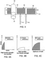
- This higher consolidation pressure shown schematically in Fig. 3 , utilizes a roller press 31, where the rollers 32, 33 of the roller press 31 create a nip through which both the copper foil 21 and anode active material 20 pass through simultaneously.
- a higher pressing pressure P1 exists when both the copper foil 21 and anode active material 20 are in the nip of roller press 31 than the pressure P2 when only the portion 34 of copper foil 21 is in the nip. It therefore becomes easy to fracture at the interface 35 of the anode active material 20 and copper foil 21.
- Fig. 4A which is a stress-strain curve of a high tensile strength, low ductility copper foil
- this copper foil is brittle and easy to fracture.
- any attempt to maintain strength by increasing the tensile strength of a copper foil while reducing its ductility leads to more brittle materials which are more easily fractured.
- the stress-strain curve of a high ductility, low tensile strength copper foil in Fig. 4B the copper foil is soft. After charging and discharging, the copper foil is easily deformed and creates wrinkles.
- Applicant has envisioned an electrodeposited copper foil of high toughness, which is determined by integrating the stress-strain curve of the copper foil. As shown in Fig. 4C , this copper foil has high tensile strength and high ductility, making the integration of the stress-strain curve a maximum value.
- an electrodeposited copper foil having a tensile strength in the range of 40 to 70 kg/mm 2 and a lightness L* value of the deposit side, based upon the L*a*b* color system, in the range of 36 to 74 the copper foil has a better toughness than foils outside these limits. If the tensile strength is lower than 40 kg/mm 2 , the strength of copper foil is lower and the copper foil is easily subjected to deformation and causes wrinkles after charging and discharging. If the tensile strength is higher than 70 kg/mm 2 , the copper foil becomes more brittle and is easy to fracture after the high pressure pressing process. In addition, the tensile strength of the electrodeposited copper foil is more preferably 40 to 60 kg/mm 2 . Further, the electrodeposited copper foil preferably has an elongation of 4.7 to 6%.
- the L*a*b* color system establishes a standard by which the color of the deposit side of an electrodeposited copper foil can be measured.
- the L* value of the deposited side based upon the L*a*b* color system, in the range of 36 to 74, such as between about 36, 40, 45, 50, 55, 60, 65, 70 and 74.
- the electrodeposited copper foil is soft. If L* value is larger than 74, the electrodeposited copper foil becomes more brittle.
- the electrodeposited copper foil has an a* value of the deposit side, in the range of 11 to 18, such as between 11, 12, 13, 14, 15, 16, or 17 and 18.
- the electrodeposited copper foil has a b* value of the deposit side, in the range of 9 to 13, or between 9, 10, 11, 12 and 13.
- the surface roughness (Rz) of the deposit side of the electrodeposited copper foil is greater than 0.5 ⁇ m and lower than 2.5 ⁇ m. In a particularly preferred embodiment, the surface roughness (Rz) of the drum side of the electrodeposited copper foil is also less than 2.5 ⁇ m.
- surface roughness is measured and provided as "Rz" standard, (utilizing JIS B 0601-1994, using an ⁇ -type surface roughness and contour measuring instrument manufactured by Kosaka Laboratory Ltd. (Model Type: SE1700), although there are other systems available to measure surface roughness. Not all measurement systems of surface roughness are equivalent. According to this Rz standard, the results are presented as an average of 10 points.
- the difference in surface roughness (Rz) between the drum side and deposit side is 1.3 ⁇ m, or less. Moreover, the difference in surface roughness (Rz) between the drum side and deposit side is more preferably 0.10 to 0.70 ⁇ m. If the surface roughness (Rz) of the deposit side is larger than 2.5 ⁇ m, the copper foil is easy to cause fracture at the interface between the anode active material and the electrodeposited copper foil after the high pressure pressing process. In preferred embodiments the surface roughness (Rz) of the drum side of the electrodeposited copper foil is lower than 2.5 ⁇ m.
- Fig. 6 illustrates the wrinkles 64 at the interface 35.
- Weight deviation sometimes occurs during the process of manufacturing copper foils.
- the weight deviation of the electrodeposited copper foil is lower than 3%.
- the weight deviation is preferably less than 2%.
- Weight deviation of electrodeposited copper foil is larger than 3%, the variations in thickness easily lead to formation of wrinkles after high pressure pressing process at the interface between the anode active material and the electrodeposited copper foil.
- a typical device 70 for manufacturing an electrodeposited copper foil is schematically illustrated in Fig. 7 .
- the manufacturing process involves dissolving copper wires in a 50 wt % sulfuric acid aqueous solution to prepare a copper sulfate electrolyte containing copper sulfate and sulfuric acid and at least one additive selected from the group consisting of gelatin, sulfonic acid modified polyvinyl alcohol, N, N'- diethylthiourea, sodium 3-mercapto-1-propane sulfonate, chloride ion and combinations thereof.
- a rotatable metal cathode drum 71 is disposed in a partially submerged position with regard to a copper-containing electrolytic solution 72.
- An insoluble metal anode 73 preferably insoluble in copper-containing electrolytic solution 72 is positioned in contact with copper-containing electrolytic solution 72.
- the insoluble metal anode 73 is arranged at approximately the lower half of the metal cathode drum 71 and surrounds the metal cathode drum 71.
- the surface 74 of the rotatable cathode drum 71 can be polished to a mirror finish, thereby imparting the same finish to the drum side 75 of copper foil 21. Rollers 76, 77, 78 assist in stripping the copper foil from drum surface 74.
- the side of the copper foil 21, opposite the drum side 75 is called the deposit side 79, because the deposit side 79 is in contact with the copper-containing electrolytic solution 72 when it is formed.
- a copper foil 21 is continuously manufactured with the device by flowing a copper -containing electrolytic solution 72 between the cathode drum 71 and the insoluble metal anode 73, applying direct current (DC) between the anode and cathode to allow copper to be deposit on the surface 74 of cathode drum 71, and detaching an electrodeposited copper foil from the cathode drum 71 when a predetermined thickness is obtained.
- the copper foil 21 so removed from drum surface74 can be immediately further processed or would upon spool 80 for storage.
- Fig. 8 illustrates a schematic embodiment where the copper foil 21 is further processed immediately after removal from the drum 71.
- Copper foil 21 is passed over guide roller 81 and into an anti-tarnish treatment tank 82.
- treatment tank 82 is a treating solution, such as an organic agent, or alternatively, a solution which can contain zinc or chromium anti-tarnish agents, which are applied to copper foil 21 to prevent anti-tarnish and/or protect the property of the copper foil 21.
- Electrodes 83, 84 can be used in the case where electrolytic deposition of a metallic layer (such as one of the aforementioned anti-tarnish metals) onto the drum side 75 of copper foil 21 is desired.
- a further electrode 85 is provided.
- a series of guide rollers 91, 92, 93 conveys the copper foil 21 through and away from treatment tank 82. Air knives 86, 87, 88 and 89 are provided to carefully regulate and dry the anti-tarnish coating, as it is desired that the anti-tarnish layer be relatively thin as compared to the thickness of the copper foil as to not deleteriously affect the surface of the copper foil 21. Additional treatment tanks (not shown) can be provided for purposes of adding additional or different types of layers. After treatment, the copper foil 21 can be wound on spool 90 for storage or shipment.
- Example 1 copper wires were dissolved in a 50 wt.% sulfuric acid solution to prepare a copper sulfate electrolyte containing 320 g/l of copper sulfate (CuSO 4 ⁇ 5H 2 O) and 100 g/l of sulfuric acid.
- the electrodeposited copper foil After being electrodeposited on a cathode drum in an electrolytic solution, the electrodeposited copper foil is fed through a series of rollers. The electrodeposited copper foil is carried through an anti-tarnish treatment before being subjected to drying with air knives. Finally, the electrodeposited copper foil is wound.
- the surface of the electrodeposited copper foil was only treated with anti-tarnish treatment (for example a chromium plating treatment, chromic acid solution dipping treatment or organic treatment), the conditions were as shown in the below Table 1, and there was nodule treatment (roughened) on the electrodeposited copper foil.
- the L*a*b* value was measured after applying an anti-tarnish treatment (anti-tarnish agent) on the copper surface.
- an insulative mask is attached to the dimensionally stable anode (insoluble metal anode) to adjust the weight deviation of the electrodeposited copper foil. Electrodeposition only occurs where the drum and the dimensionally stable anode are conductive. See US Patent 9,711,799 .
- Table 2 illustrates the parameter condition for producing copper foils in the Examples and Comparative Examples.
- Table 2 Conditions Example 1 2 3 4 5 6 7 8 9 10 Manufacture of Electrodeposited Copper Foil Copper Sulfate (g/l) 320 320 320 320 320 320 320 320 320 320 320 320 320 320 320 320 320 320 320 320 320 320 320 320 320 320 320 320 320 Sulfuric acid (g/l) 100 100 100 100 100 100 100 100 100 100 100 100 100 100 100 100 100 100 100 100 100 100 100 100 100 100 100 100 100 100 100 100 100 100 100 100 100 100 100 100 100 100 100 100 100 100 100 100 100 100 100 100 100 100 100 100 100 100 100 100 100 100 100 100 100 100 100 100 100 100 100 100 100 100 100 100 100 100 100 100 100 100 100 100 100 100 100 100 100 100 100 100 100 100 100 100 100 100 100 100 100 100 100 100 100 100 100 100 100 100 100 100 100 100 100 100 100 100 100 100 100 100 100 100 100 100 100 100 100
- the electrodeposited copper foil was cut to obtain a test sample with the size of 100 mm x 12.7 mm (length x width), and the test sample was measured at room temperature (about 25°C) under the conditions of a chuck distance of 50 mm and a crosshead speed of 50 mm/min. by using Model AG-I testing machine of Shimadzu Corporation.
- the electrodeposited copper foil was cut to obtain a test sample of 100 mm x 12.7 mm (length x width), and the test sample was measured at room temperature (about 25°C) under the conditions of a chuck distance of 50 mm and a crosshead speed of 50 mm/min. by using Model AG-I testing machine of Shimadzu Corporation.
- the measurement was conducted based on the method of JIS B 0601-1994 by using ⁇ Type Surface Roughness and Profile Measuring Instrument (Kosaka Laboratory Ltd.; SE 1700 Series).
- Rz Surface roughness (Ten points Mean Roughness) is obtained from the total in micron meter of the mean value of each distance between the mean line and the 5 peaks from the highest one and the 5 valleys from the lowest one, of the roughness curve in the range of sampled reference length.
- L*, a* and b* are numeric values determines based on the L*a*b* color system described in JIS Z 8729 and the measurement based on the method of JIS Z 8722 by using SPECTROPHOTOMETER (Konica-Minolta; CM2500c). In the measurement, a viewing angle (observer) is 2°, and a light source (illuminant) was D65.
- the electrodeposited copper foil is cut into small pieces of 50 mm in length x 50 mm in width.
- a microbalance AG-204 manufactured by Mettler Toledo International Inc. was used to measure the test pieces. For each test piece, the numeric weight value of the reading was multiplied by 400 to obtain an area weight (g/m 2 ).
- Weight deviation % Maximum area weight g / m 2 ⁇ minimum area weight g / m 2 Average area weight g / m 2 ⁇ 100
- An anode slurry was prepared using N-Methyl-2-pyrrolidone (NMP) as a solvent and the anode materials listed in the table 3 below with a solid-liquid ratio of 60% (100 g of anode materials; 60 g of NMP). After the components of the anode material formulation are mixed, the carbon material is coated on the surface of copper foil at a speed of 5 meters per minute to a thickness of 200 ⁇ m and then dried through a 160 °C oven.
- NMP N-Methyl-2-pyrrolidone
- the anode (copper foil + anode active material) was then pressed in a roller press.
- the dimensions of the rollers of the roller press were 250 mm x 250 mm, hardness of the rollers was 62 ⁇ 65°HRC, and the roller material was high-carbon chrome bearing steel (SUJ2).
- a 1 M/min. pressing speed and 3000 psi pressure were used and then the pressed materials were observed to determine whether the interface between the copper foil and the anode active material were fractured or not.
- the evaluation was made according to the following standards: x: fully fractured
- An anode slurry was prepared using N-Methyl-2-pyrrolidone (NMP) as a solvent and the anode materials listed in the table 4 below with a solid-liquid ratio of 60% (100 g of anode materials; 60 g of NMP). After the components of the anode material formulation are mixed, the carbon material is coated on the surface of copper foil at a speed of 5 meters per minute to a thickness of 200 ⁇ m and then dried through a 160 °C oven.
- NMP N-Methyl-2-pyrrolidone
- the anode (copper foil + anode active material) was then pressed in a roller press.
- the dimensions of the rollers of the roller press were 250 mm x 250 mm, hardness of the rollers was 62 ⁇ 65°HRC, and the roller material was high-carbon chrome bearing steel (SUJ2).
- a 1 M/min. pressing speed and 3000 psi pressure were used and then the pressed materials were observed to determine whether the interface between the copper foil and the anode active material were wrinkle or not.
- a laminated type lithium secondary battery was prepared as follows and subjected to a high c-rate charging and discharging test.
- N-methyl-2-pyrrolidone (NMP) was used as a solvent for a cathode material (at a solid to liquid ratio of 195 wt.% (100 g of the cathode material: 195 g of NMP) as shown in the table 5 below, so as to obtain a cathode slurry.
- NMP was used as a solvent for an anode material (at a solid to liquid ratio of 60 wt.% (100 g of the anode material: 60 g of NMP), so as to obtain an anode slurry.
- Cathode Material formulation Based on the total weight of the cathode material Cathode active material(LiCoO 2 ) 89 wt.% Conductive Additive (Flaked graphite; KS6) 5 wt.% Conductive additive (Conductive carbon powder; Super P ® ) 1 wt.% Solvent -Based Binder (PVDF1300) 5 wt.% Anode material formulation: Based on the total weight of the anode material Anode active material (MGPA) 93.9 wt.% Conductive additive (Conductive carbon powder; Super P ® ) 1 wt.% Solvent-Based binder (PVDF6020) 5 wt.% Oxalic acid 0.1 wt.%
- the cathode slurry was coated on aluminum foil, and the anode slurry was coated on the copper foils. After the solvents evaporated, the anode and cathode were pressed and slitted into certain sizes. Afterwards, cathodes and anodes are alternately stacked with a separator (manufactured by Celgard Company) sandwiched between, and placed in a container molded by laminate film. The container was then filled with an electrolyte, and sealed to form a battery.
- the size of the laminated type lithium secondary battery was 41 mm x 34 mm x 53 mm.
- the charging mode was the constant current-constant voltage (CCCV) mode, the charging voltage was 4.2 V, and the charging current was 5C.
- CCCV constant current-constant voltage
- the discharging mode was the constant current (CC) mode, the discharging voltage was 2.8 V, and the discharging current was 5C.
- the charging-discharging test on the batteries was conducted at high temperature (55 °C).
Landscapes
- Chemical & Material Sciences (AREA)
- Engineering & Computer Science (AREA)
- Chemical Kinetics & Catalysis (AREA)
- Electrochemistry (AREA)
- Materials Engineering (AREA)
- General Chemical & Material Sciences (AREA)
- Organic Chemistry (AREA)
- Metallurgy (AREA)
- Manufacturing & Machinery (AREA)
- Composite Materials (AREA)
- Cell Electrode Carriers And Collectors (AREA)
- Secondary Cells (AREA)
- Battery Electrode And Active Subsutance (AREA)
Description
- The present disclosure describes an electrodeposited copper foil, and a method of making the copper foil, which copper foil has a high toughness property, primarily for use as a current collector in rechargeable lithium secondary battery, especially laminated type high energy capacity lithium secondary battery. A method for making a rechargeable battery utilizing the electrodeposited copper foil of high toughness is also disclosed.
- Electrification is the most viable way to achieve clean and efficient transportation that is crucial to the sustainable development of the entire world. In the near future, electric vehicles (EV), including hybrid electric vehicles (HEVs), plug-in hybrid electric vehicles (PHEVs), and pure battery electric vehicles (BEVs) will dominate the clean vehicle market. By 2020, it is expected that more than half of new vehicle sales will likely be EV models. The key and the enabling technology to this revolutionary change in transportation is the battery. EV batteries are quite different from those used in consumer electronic devices, such as laptops and cellphones. They are required to handle high power (up to a hundred kW) and have high energy capacity (up to tens of kW) within a limited space and weight and at an affordable price. The current two major battery types used in EVs today are nickel metal hydride (NiMH) and lithium type. Nearly all HEVs available in the market today use NiMH batteries because of its mature technology. Due to the potential of obtaining higher specific energy and energy density, the adoption of lithium secondary batteries is expected to grow fast in EVs, particularly in PHEVs and BEVs.
- Laminated type lithium secondary batteries for both EV and HEV applications feature a structure in which stacked cathodes and anodes are alternately stacked with a separator sandwiched between and then sealed with a laminate film. The batteries are able to achieve a large capacity because of having an extremely compact shape. In addition, because of the simple structure, the batteries are lightweight and maintain a competitive advantage from a cost perspective as well.
- A laminated type lithium secondary battery that boasts of advanced heat dissipation as compared to conventional cylindrical batteries. Because the laminated type lithium secondary battery has a broad surface area, the battery is better able to dissipate heat, and increases in the overall temperature of the battery due to charging and discharging can be kept low. Therefore, electric vehicles that adopt batteries of laminated type can simplify countermeasures against heat.
- Cylindrical lithium secondary batteries (also known as wound type batteries), have an anode and a cathode which are cut into two long strips, and together with a separator, that keeps the anode and cathode apart, are wound on a cylindrical mandrel, to form a jelly roll (also known as a Swiss roll in the United Kingdom). Cylindrical battery thus has only two electrode strips which simplifies the construction of the battery considerably. The cylindrical design has good cycling ability, offers a long calendar life and is economical, but is heavy and has low packaging density due to it space cavities. The cylindrical cell is commonly used for portable applications.
- Essentially, high elongation copper foil is more appropriate as a current collector in cylindrical batteries. When a cylindrical battery expands during its charge and discharge, the outermost circle of copper foil will expand more than the innermost (or inner) circles. If the copper foil does not possess high elongation, the outermost circle of copper foil will easily fracture.
- Heretofore, a copper foil was used as a current collector of negative electrode (anode) in rechargeable lithium secondary batteries. The surface of the copper foil was coated with a layer of anode active material. Because the layer of anode active material expands and shrinks as it stores and releases lithium-ion, a stress is engendered in the current collector (copper foil) during a charge-discharge cycle and occasionally causes formation of wrinkles. The formation of wrinkles in the copper foil not only increases a volume of the negative electrode (anode) but also disturbs uniformity of an electrode reaction, resulting in a reduction of an energy density.
- For laminated type lithium secondary battery, the expansion of the copper foil in X or Y direction of a laminated battery is not as much as in the cylindrical lithium secondary battery. Thus, the art has tended to use high tensile strength copper foils as a more appropriate current collector in laminated type lithium secondary battery. When a copper foil has high tensile strength, the copper foil has a high strength, it is more difficult to deform and cause wrinkles in the copper foil during the charge/discharge cycle of the battery.
- In order to have high energy capacity, the thickness of the copper foil needs to be decreased, because at a same volume of a lithium secondary battery, more active materials can be employed. However, when the thickness of the copper foil decreases, the strength of the copper foil also decreases. After charging/discharging cycle of the battery, the thinner copper foil is easy to deform and cause wrinkles. Up until this disclosure, people like to use high tensile strength copper foil, which is difficult to deform thus causing wrinkles. However, for a conventional copper foil, when one increases the tensile strength of the foil, one basically reduces its elongation. It means that the copper foil becomes strong, but brittle.
- In order for a lithium secondary battery to have a higher energy capacity, in addition to decreasing the thickness of the copper foil, a higher pressing pressure, used to condense the anode active material on the copper foil's surface, is necessary so that the lithium secondary battery can contain more anode active material. The use of conventional copper foil, of high tensile strength, means that the copper foil is not easy to deform and cause wrinkle during the charging/discharging cycle. However, this conventional copper foil, being brittle, is easily fractured at the interface of the copper foil/anode active material (carbon material) if the copper foil is subjected to higher pressure during pressing to consolidate the anode active material.
- Accordingly, all these deficiencies in the prior art copper foils, especially copper foils for use as current collectors in currently available laminated type lithium secondary batteries, required the present inventors to not only recognize the deficiencies in current batteries and the components of such batteries, but also to formulate new copper foils, composites of copper foil/anode active materials, methods of production employing higher pressing pressures used to consolidate greater amounts of anode active materials, and to provide improved lithium secondary batteries of high capacity than heretofore available for the same volume battery. It is desirable to provide a rechargeable secondary battery, an electric tool, an electric vehicle, and a power storage system which can obtain an excellent battery capacity characteristic and cycle characteristics.
US Patent 9 711 799 JP Patent 5810249 US Patent 9 397 343 - A strength of a material, in particular, a copper foil, is calculated by the following relationship:

- When copper foil has a high strength, it is more difficult to cause deformation and wrinkles. If two copper foils have the same tensile strength, the thicker copper foil will have the higher strength. If two copper foils have the same thickness, the higher tensile strength copper foil will have the higher strength. If a thickness of a copper foil is made to decrease, it is necessary to increase the tensile strength of the foil in order to maintain the strength of the foil. High strength does not necessarily mean high toughness, but high toughness represents high strength.
- The new copper foils for use as components of a lithium secondary battery, in particular, a laminated type lithium secondary battery, must possess toughness, not merely high tensile strength. Toughness can be determined by integrating the stress-strain curve of a material, in this case, a copper foil. It is the energy of mechanical deformation per unit volume prior to fracture. In order to be tough, a copper foil which has both strong (high tensile strength) and ductile (high elongation) is an essential requirement.
- Therefore, it is an object of the present disclosure to provide an electrodeposited copper foil which has high toughness property for use in rechargeable lithium secondary battery, especially laminated type high energy capacity battery.
- It is an further object of the disclosure to provide a process of manufacturing an electrodeposited copper foil of high toughness by depositing on the surface of a rotating drum, with the surface of the rotating drum at least partially immersed in a copper-containing electrolytic solution, under the influence of an electric current passing through the electrolytic solution, with the drum acting as cathode and at least one anode in contact with the electrolytic solution, to form a copper foil. The surface of the copper foil formed against the drum is termed the "drum side" of the copper foil. The opposite surface of the copper foil, or that portion of the copper foil which faced the electrolytic solution during formation, is called the "deposit side" of the copper foil.
- It is also an object of the present disclosure to provide a method of manufacturing an anode for a lithium secondary battery from a composite of an electrodeposited copper foil and anode active material by pressing where the electrodeposited copper foil used in the manufacturing is not only resistant to deformation and wrinkles when used in a battery after charging and discharging, but also resistant to fracture at the interface of the anode active material and the electrodeposited copper foil after high pressure pressing to consolidate the anode active material on the electrodeposited copper foil.
- The present invention is defined by the electrodeposited copper foil of
claim 1, this foil having a drum side, being the surface of the copper foil formed against a drum, and a deposit side opposite to the drum side, the electrodeposited copper foil being characterized by having: - a tensile strength in a range of 40 kg/mm2 to 70 kg/mm2, and preferably in the range of 40 kg/mm2 to 60 kg/mm2,
- wherein a surface roughness (Rz) of the deposit side of the electrodeposited copper foil is greater than 0.5 µm and lower than 2.5 µm, and a difference in the surface roughness between the drum side and the deposit side is at most 1.3 µm, and preferably, in a range of 0.10 µm to 0.70 µm;
- a lightness L* value of the deposit side, based on the L*a*b* color system described in JIS Z 8729, in a range of 36 to 74; and
- a weight deviation calculated according to the following relationship:

- It is a still further object of the invention to provide components of a rechargeable lithium secondary battery utilizing the aforementioned electrodeposited copper foil, in conjunction with anode active material, to act as a current collector in the battery.
- It is a further object to disclose methods of manufacturing a high capacity laminated type lithium secondary battery and a rechargeable lithium secondary battery containing the electrodeposited copper foil disclosed herein as a component thereof.
- The foregoing and additional objects of the invention will be best understood with the following description of the preferred embodiments in conjunction with the appended drawings.
-
-
Fig. 1A is an exploded schematic view of the stacked electrodes in a laminated type lithium secondary battery; -
Fig. 1B is a schematic view of the stacked electrodes ofFig. 1 A , with lead tabs being attached to the stacked electrodes between laminate films; -
Fig. 1C illustrates a final form of a laminated type lithium secondary battery; -
Fig. 2 is a schematic representation of anode active material in combination with the copper foil according to one embodiment of the disclosure, and additionally illustrates the X, Y and Z-axes of the copper foil; -
Fig. 3 is a schematic illustration of the process of consolidating an active anode material by pressing the anode active material and copper foil with a roller press; -
Fig. 4A is a graphic representation of a stress-strain curve of a high tensile strength, low ductility copper foil; -
Fig. 4B is a graphic representation of a high ductility, low tensile strength copper foil; -
Fig. 4C is a graphic representation of toughness property of a copper foil obtained by integrating the stress-strain curve; -
Fig. 5 is a graphic comparison of the stress-strain curves of three copper foils A, B and C; -
Fig. 6 is a schematic illustration depicting wrinkles at the interface of a copper foil and anode active material consolidated on the copper foil; -
Fig. 7 is a schematic representation of an apparatus for making the electrodeposited copper foil according to a preferred embodiment; -
Fig. 8 is a schematic representation of an apparatus for making the electrodeposited copper foil according to a preferred embodiment including the steps of applying an anti-tarnish agent to the formed electrodeposited copper foil; and, -
Fig. 9 is a partially cross-sectioned schematic illustration of a cylindrical battery. - As used throughout the various drawing figures, like elements in different views may be given a common numeral labeling, to assist the reader in understanding the various embodiments.
- The laminated type battery is formed by discontinuously placing an anode active material along a portion of the electrodeposited copper foil. Together, they are fed into nip of a roller press and consolidated under pressure to form an anode. The anode is then stacked with cathode in an alternating manner in a container, with a separator placed between each adjacent anode/cathode. Container is then filled with electrolyte and sealed to form a laminated type lithium secondary battery. As shown in
Fig. 1C is a laminated type rechargeable lithiumsecondary battery 10 havinglead tab 11 for connection of thebattery 10 to external system components of the EV (not shown).Laminate film battery 10 as shown inFig. 1B .Lead tab 11 can also be seen attached to the stackedelectrodes 16 inFig. 1B . The exploded view ofFig. 1A more clearly illustrates the components of the stacked electrodes ofFig. 1B . A plurality ofanodes 15 andcathodes 17 are stacked withseparators 19 placed between eachadjacent anode 15 andcathode 17 in the stack. Theanode 15 comprises an anodeactive material copper foil 21 according to the present disclosure as shown inFig. 2 . In a laminated type lithiumsecondary battery 10, the expansion along the X and Y axes of the copper foil is not as much as the expansion of thenegative electrode 92 of acylindrical battery 90 as shown inFig. 9 . - In order to increase the capacity of the
battery 10, a reduction in the thickness of the copper foil would permit an increased number of anodes in a given volume of thebattery 10. However, decreasing the thickness of a copper foil of given tensile strength also reduces its strength. The relationship between strength and tensile strength can be visualized by the following relationship:
- Thus, strength of the copper foil can be made greater by increasing the thickness of the foil; by increasing the tensile strength of a copper foil; or increasing both the thickness and tensile strength of the copper foil. However, if it is required to reduce the thickness of the copper foil, in order to increase the electrical capacity of a lithium secondary battery of given volume, then one must increase the tensile strength of the copper foil to maintain its strength. However, the present applicant has found that increasing the tensile strength of a copper foil for use in a rechargeable lithium secondary battery presents new disadvantages. Increasing the tensile strength of a copper foil makes it brittle. Furthermore, in order to consolidate more of the anode
active material 20 on thecopper foil 21, a higher consolidation pressure must be applied to each of the anodeactive material 20 and thecopper foil 21. This higher consolidation pressure, shown schematically inFig. 3 , utilizes aroller press 31, where therollers roller press 31 create a nip through which both thecopper foil 21 and anodeactive material 20 pass through simultaneously. As the anodeactive material 20 is positioned intermittently oncopper foil 21, it is clear that a higher pressing pressure P1 exists when both thecopper foil 21 and anodeactive material 20 are in the nip ofroller press 31 than the pressure P2 when only theportion 34 ofcopper foil 21 is in the nip. It therefore becomes easy to fracture at theinterface 35 of the anodeactive material 20 andcopper foil 21. - Therefore, the present applicant has devised a new electrodeposited copper foil having a high toughness, rather than merely a high tensile strength. As shown in
Fig. 4A , which is a stress-strain curve of a high tensile strength, low ductility copper foil, this copper foil is brittle and easy to fracture. Thus, any attempt to maintain strength by increasing the tensile strength of a copper foil while reducing its ductility leads to more brittle materials which are more easily fractured. On the other hand, as shown in the stress-strain curve of a high ductility, low tensile strength copper foil inFig. 4B , the copper foil is soft. After charging and discharging, the copper foil is easily deformed and creates wrinkles. Applicant has envisioned an electrodeposited copper foil of high toughness, which is determined by integrating the stress-strain curve of the copper foil. As shown inFig. 4C , this copper foil has high tensile strength and high ductility, making the integration of the stress-strain curve a maximum value. - This will be better understood by reference to
Fig. 5 where the stress-strain curves of three copper foils A, B and C are all plotted on the same scale. According to the stress-strain curves of copper foils A, B and C, they each possess the same tensile stress and ductility (elongation), but copper foil A has a higher toughness than copper foils B and C. Even if the copper foil has the same tensile strength and elongation, it does not mean that it has the same toughness. Applicant has found that an electrodeposited copper foil having a tensile strength in the range of 40 to 70 kg/mm2 and a lightness L* value of the deposit side, based upon the L*a*b* color system, in the range of 36 to 74, the copper foil has a better toughness than foils outside these limits. If the tensile strength is lower than 40 kg/mm2, the strength of copper foil is lower and the copper foil is easily subjected to deformation and causes wrinkles after charging and discharging. If the tensile strength is higher than 70 kg/mm2, the copper foil becomes more brittle and is easy to fracture after the high pressure pressing process. In addition, the tensile strength of the electrodeposited copper foil is more preferably 40 to 60 kg/mm2. Further, the electrodeposited copper foil preferably has an elongation of 4.7 to 6%. - Identifying Color Differences Using CIE L*a*b* Coordinates. Differences in color between two objects cannot always be apparent to the unaided human eye. Thus, optically aided devices, such as those sold by the Konica-Minolta company, under its brand for the spectrophotometer CM-2500c are often used. Of course, other devices may be substituted for the spectrophotometer of the Konica-Minolta device. As defined by the Commission Internationale de l'Eclairage (CIE), the L*a*b* color space was modeled after a color-opponent theory stating that two colors cannot be red and green at the same time or yellow and blue at the same time. In the L*a*b* color system, L* indicates lightness, a* is the red/green coordinate, and b* is the yellow/blue coordinate.
- Thus, the L*a*b* color system establishes a standard by which the color of the deposit side of an electrodeposited copper foil can be measured. As noted above, the L* value of the deposited side, based upon the L*a*b* color system, in the range of 36 to 74, such as between about 36, 40, 45, 50, 55, 60, 65, 70 and 74. When the lightness value L* of the deposit side is lower than 36, the electrodeposited copper foil is soft. If L* value is larger than 74, the electrodeposited copper foil becomes more brittle. In some cases, the electrodeposited copper foil has an a* value of the deposit side, in the range of 11 to 18, such as between 11, 12, 13, 14, 15, 16, or 17 and 18. In some cases, the electrodeposited copper foil has a b* value of the deposit side, in the range of 9 to 13, or between 9, 10, 11, 12 and 13.
- It is also important that the surface roughness (Rz) of the deposit side of the electrodeposited copper foil is greater than 0.5 µm and lower than 2.5 µm. In a particularly preferred embodiment, the surface roughness (Rz) of the drum side of the electrodeposited copper foil is also less than 2.5µm. As used throughout this specification and claims, surface roughness is measured and provided as "Rz" standard, (utilizing JIS B 0601-1994, using an α-type surface roughness and contour measuring instrument manufactured by Kosaka Laboratory Ltd. (Model Type: SE1700), although there are other systems available to measure surface roughness. Not all measurement systems of surface roughness are equivalent. According to this Rz standard, the results are presented as an average of 10 points. Furthermore, the difference in surface roughness (Rz) between the drum side and deposit side is 1.3 µm, or less. Moreover, the difference in surface roughness (Rz) between the drum side and deposit side is more preferably 0.10 to 0.70 µm. If the surface roughness (Rz) of the deposit side is larger than 2.5µm, the copper foil is easy to cause fracture at the interface between the anode active material and the electrodeposited copper foil after the high pressure pressing process. In preferred embodiments the surface roughness (Rz) of the drum side of the electrodeposited copper foil is lower than 2.5 µm. If the difference in surface roughness (Rz) between the drum side and the deposit side is larger than 1.3 µm, it is easy to cause wrinkles after high pressure pressing process at the
interface 35 between anodeactive material 20 and thecopper foil 21.Fig. 6 illustrates thewrinkles 64 at theinterface 35. - Weight deviation sometimes occurs during the process of manufacturing copper foils. However, when making electrodeposited copper foils according to this disclosure, the weight deviation of the electrodeposited copper foil is lower than 3%. The weight deviation is preferably less than 2%. Weight deviation is calculated according to the following relationship:

- A
typical device 70 for manufacturing an electrodeposited copper foil is schematically illustrated inFig. 7 . The manufacturing process involves dissolving copper wires in a 50 wt % sulfuric acid aqueous solution to prepare a copper sulfate electrolyte containing copper sulfate and sulfuric acid and at least one additive selected from the group consisting of gelatin, sulfonic acid modified polyvinyl alcohol, N, N'- diethylthiourea, sodium 3-mercapto-1-propane sulfonate, chloride ion and combinations thereof. A rotatablemetal cathode drum 71 is disposed in a partially submerged position with regard to a copper-containingelectrolytic solution 72. Aninsoluble metal anode 73, preferably insoluble in copper-containingelectrolytic solution 72 is positioned in contact with copper-containingelectrolytic solution 72. Theinsoluble metal anode 73 is arranged at approximately the lower half of themetal cathode drum 71 and surrounds themetal cathode drum 71. Thesurface 74 of therotatable cathode drum 71 can be polished to a mirror finish, thereby imparting the same finish to thedrum side 75 ofcopper foil 21.Rollers drum surface 74. The side of thecopper foil 21, opposite thedrum side 75 is called thedeposit side 79, because thedeposit side 79 is in contact with the copper-containingelectrolytic solution 72 when it is formed. Acopper foil 21 is continuously manufactured with the device by flowing a copper -containingelectrolytic solution 72 between thecathode drum 71 and theinsoluble metal anode 73, applying direct current (DC) between the anode and cathode to allow copper to be deposit on thesurface 74 ofcathode drum 71, and detaching an electrodeposited copper foil from thecathode drum 71 when a predetermined thickness is obtained. Thecopper foil 21 so removed from drum surface74 can be immediately further processed or would uponspool 80 for storage. -
Fig. 8 illustrates a schematic embodiment where thecopper foil 21 is further processed immediately after removal from thedrum 71.Copper foil 21 is passed overguide roller 81 and into ananti-tarnish treatment tank 82. Intreatment tank 82 is a treating solution, such as an organic agent, or alternatively, a solution which can contain zinc or chromium anti-tarnish agents, which are applied tocopper foil 21 to prevent anti-tarnish and/or protect the property of thecopper foil 21.Electrodes drum side 75 ofcopper foil 21 is desired. If it is desired to electrolytically deposit a metal on thedeposit side 79 ofcopper foil 21, afurther electrode 85 is provided. A series ofguide rollers copper foil 21 through and away fromtreatment tank 82.Air knives copper foil 21. Additional treatment tanks (not shown) can be provided for purposes of adding additional or different types of layers. After treatment, thecopper foil 21 can be wound onspool 90 for storage or shipment. - The embodiments of the disclosure can be further understood in connection with the following Examples and Comparative Examples and the testing procedures describe hereinafter. It should be clearly understood that these are additional and more favorable conditions for achieving the electrodeposited copper foil for a lithium secondary battery according to the present invention. It should be understood within the scope of the present disclosure, the above-mentioned technical features and technical features mentioned below (such as example) can be combined freely and mutually to form new or preferred technical solutions, which are omitted for brevity.
- In Example 1, copper wires were dissolved in a 50 wt.% sulfuric acid solution to prepare a copper sulfate electrolyte containing 320 g/l of copper sulfate (CuSO4·5H2O) and 100 g/l of sulfuric acid. To per liter of the copper sulfate electrolyte, 0.8 mg of gelatin (DV: Nippi Company), 1.0 mg of sulfonic acid modified polyvinyl alcohol (TA-02F; Chang Chun Petrochemical Co., Ltd.), 1.3 mg of sodium 3-mercapto-1-propanesulfonate (MPS: HOPAX Company), 1.5 mg of N, N' -Diethylthiourea (Alfa Aesar®; A Johnson Matthey Company) and 40 mg chloride ion were added. Subsequently, an electrodeposited copper foil with a thickness of 6 µm was prepared at a liquid temperature of 50 °C and a current density of 50 A/dm2.
- After being electrodeposited on a cathode drum in an electrolytic solution, the electrodeposited copper foil is fed through a series of rollers. The electrodeposited copper foil is carried through an anti-tarnish treatment before being subjected to drying with air knives. Finally, the electrodeposited copper foil is wound. The surface of the electrodeposited copper foil was only treated with anti-tarnish treatment (for example a chromium plating treatment, chromic acid solution dipping treatment or organic treatment), the conditions were as shown in the below Table 1, and there was no nodule treatment (roughened) on the electrodeposited copper foil. The L*a*b* value was measured after applying an anti-tarnish treatment (anti-tarnish agent) on the copper surface.
Table 1 Anti-tarnish treatment conditions pH Current Density (A/dm2) Plating or dipping time (Sec.) Temperature of solution (°C) Anti-tarnish Agent Chromium Plating CrO3 1.5 g/l 2.03 0.5 2 25 Chromic Acid solution Dipping CrO3 1.5 g/l 2.03 0 2 25 Organic treatment BTA (1,2,3-benzotriazole) 0.02% - 0 2 25 - To control weight deviation, an insulative mask is attached to the dimensionally stable anode (insoluble metal anode) to adjust the weight deviation of the electrodeposited copper foil. Electrodeposition only occurs where the drum and the dimensionally stable anode are conductive. See
US Patent 9,711,799 - The following Table 2 illustrates the parameter condition for producing copper foils in the Examples and Comparative Examples.
Table 2 Conditions Example 1 2 3 4 5 6 7 8 9 10 Manufacture of Electrodeposited Copper Foil Copper Sulfate (g/l) 320 320 320 320 320 320 320 320 320 320 Sulfuric acid (g/l) 100 100 100 100 100 100 100 100 100 100 Concentration of gelatin (mg/l) 0.8 0.8 0.8 0.8 0.8 0.7 0.8 0.8 0.8 0.8 Concentration of sulfonic acid modified polyvinyl alcohol (mg/l) 1.0 1.5 1.5 1.5 1.0 0.9 1.0 1.0 1.0 1.0 Concentration of N,N'-Diethylthiourea (mg/l) 1.5 1.0 2.5 3.0 1.5 1.3 1.5 1.5 1.5 1.5 Concentration of sodium 3-mercapto-1-propanesulfonate (mg/l) 1.3 2.6 1.3 1.3 2.0 1.1 1.3 1.3 1.3 1.3 Chloride ion (mg/l) 40 40 40 40 40 40 40 40 40 40 Temperature (°C) 50 50 50 45 50 50 50 50 50 50 Current density (A/dm2) 50 50 50 50 50 50 50 50 50 50 Surface Anti-Tarnish Treatment CrO3 (g/l) 1.5 1.5 1.5 1.5 1.5 1.5 - - 1.5 - BTA (%) - - - - - - 0.02 0.01 - - Temperature (°C) 25 25 25 25 25 25 25 25 25 - Current density (A/dm2) 0.5 0.5 0.5 0.5 0.5 0.5 - - 0 - Time (Sec.) 2 2 2 2 2 2 2 2 2 - pH 2.03 2.03 2.03 2.03 2.03 2.03 - - 2.03 - Conditions Comparative Example 1 2 3 4 5 6 7 Manufacture of Electrodeposited Copper Foil Copper Sulfate (g/l) 320 320 320 320 320 320 320 Sulfuric acid (g/l) 100 100 100 100 100 100 100 Concentration of gelatin (mg/l) 0.8 0.8 0.8 0.8 0.8 0.8 0.4 Concentration of sulfonic acid modified polyvinyl alcohol (mg/l) 1.0 1.5 1.5 0.5 1.0 1.5 0.8 Concentration of N, N'-Diethylthiourea (mg/l) 0 1.0 3.0 3.0 1.5 2.5 1.2 Concentration of sodium 3-mercapto-1-propanesulfonate (mg/l) 1.6 2.6 0.8 1.3 1.3 2.6 1.2 Chloride ion (mg/l) 30 50 40 30 40 40 40 Temperature (°C) 50 50 45 45 50 45 45 Current density (A/dm2) 50 50 50 50 50 50 50 Surface Anti-Tarnish Treatment CrO3 (g/l) 1.5 1.5 1.5 1.5 1.5 1.5 - BTA (%) - - - - - - - Temperature (°C) 25 25 25 25 25 25 25 Current density (A/dm2) 0.5 0.5 0.5 0.5 0.5 0.5 - Time (Sec.) 2 2 2 2 2 2 2 pH 2.03 2.03 2.03 2.03 2.03 2.03 2.03 - Based on the method of IPC-TM-650, the electrodeposited copper foil was cut to obtain a test sample with the size of 100 mm x 12.7 mm (length x width), and the test sample was measured at room temperature (about 25°C) under the conditions of a chuck distance of 50 mm and a crosshead speed of 50 mm/min. by using Model AG-I testing machine of Shimadzu Corporation.
- Based on the method of IPC-TM-650, the electrodeposited copper foil was cut to obtain a test sample of 100 mm x 12.7 mm (length x width), and the test sample was measured at room temperature (about 25°C) under the conditions of a chuck distance of 50 mm and a crosshead speed of 50 mm/min. by using Model AG-I testing machine of Shimadzu Corporation.
- The measurement was conducted based on the method of JIS B 0601-1994 by using α Type Surface Roughness and Profile Measuring Instrument (Kosaka Laboratory Ltd.; SE 1700 Series).
- Surface roughness (Rz) (Ten points Mean Roughness) is obtained from the total in micron meter of the mean value of each distance between the mean line and the 5 peaks from the highest one and the 5 valleys from the lowest one, of the roughness curve in the range of sampled reference length.
- L*, a* and b* are numeric values determines based on the L*a*b* color system described in JIS Z 8729 and the measurement based on the method of JIS Z 8722 by using SPECTROPHOTOMETER (Konica-Minolta; CM2500c). In the measurement, a viewing angle (observer) is 2°, and a light source (illuminant) was D65.
- The electrodeposited copper foil is cut into small pieces of 50 mm in length x 50 mm in width. A microbalance (AG-204) manufactured by Mettler Toledo International Inc. was used to measure the test pieces. For each test piece, the numeric weight value of the reading was multiplied by 400 to obtain an area weight (g/m2).

- An anode slurry was prepared using N-Methyl-2-pyrrolidone (NMP) as a solvent and the anode materials listed in the table 3 below with a solid-liquid ratio of 60% (100 g of anode materials; 60 g of NMP). After the components of the anode material formulation are mixed, the carbon material is coated on the surface of copper foil at a speed of 5 meters per minute to a thickness of 200 µm and then dried through a 160 °C oven.
- The anode (copper foil + anode active material) was then pressed in a roller press. The dimensions of the rollers of the roller press were 250 mm x 250 mm, hardness of the rollers was 62~65°HRC, and the roller material was high-carbon chrome bearing steel (SUJ2). A 1 M/min. pressing speed and 3000 psi pressure were used and then the pressed materials were observed to determine whether the interface between the copper foil and the anode active material were fractured or not. The evaluation was made according to the following standards:
x: fully fractured - : partially fractured

- o: no fracture
- An anode slurry was prepared using N-Methyl-2-pyrrolidone (NMP) as a solvent and the anode materials listed in the table 4 below with a solid-liquid ratio of 60% (100 g of anode materials; 60 g of NMP). After the components of the anode material formulation are mixed, the carbon material is coated on the surface of copper foil at a speed of 5 meters per minute to a thickness of 200 µm and then dried through a 160 °C oven.
- The anode (copper foil + anode active material) was then pressed in a roller press. The dimensions of the rollers of the roller press were 250 mm x 250 mm, hardness of the rollers was 62~65°HRC, and the roller material was high-carbon chrome bearing steel (SUJ2). A 1 M/min. pressing speed and 3000 psi pressure were used and then the pressed materials were observed to determine whether the interface between the copper foil and the anode active material were wrinkle or not. The evaluation was made according to the following standards:
x: wrinkle
o: no wrinkleAnode Material Based on Total Weight of Anode Materials Anode active Material (Mesophase Graphite Powder Anode; MGPA) 93.9 wt.% Conductive Additive (Conductive Carbon Black; Super P®) 1 wt.% Solvent-Based Binder (PVDF 6020, i.e., polyvinylidene fluoride) 5 wt.% Oxalic Acid 0.1 wt.% - A laminated type lithium secondary battery was prepared as follows and subjected to a high c-rate charging and discharging test. N-methyl-2-pyrrolidone (NMP) was used as a solvent for a cathode material (at a solid to liquid ratio of 195 wt.% (100 g of the cathode material: 195 g of NMP) as shown in the table 5 below, so as to obtain a cathode slurry. NMP was used as a solvent for an anode material (at a solid to liquid ratio of 60 wt.% (100 g of the anode material: 60 g of NMP), so as to obtain an anode slurry.
Table 5 Cathode Material formulation: Based on the total weight of the cathode material Cathode active material(LiCoO2) 89 wt.% Conductive Additive (Flaked graphite; KS6) 5 wt.% Conductive additive (Conductive carbon powder; Super P®) 1 wt.% Solvent -Based Binder (PVDF1300) 5 wt.% Anode material formulation: Based on the total weight of the anode material Anode active material (MGPA) 93.9 wt.% Conductive additive (Conductive carbon powder; Super P®) 1 wt.% Solvent-Based binder (PVDF6020) 5 wt.% Oxalic acid 0.1 wt.% - Then, the cathode slurry was coated on aluminum foil, and the anode slurry was coated on the copper foils. After the solvents evaporated, the anode and cathode were pressed and slitted into certain sizes. Afterwards, cathodes and anodes are alternately stacked with a separator (manufactured by Celgard Company) sandwiched between, and placed in a container molded by laminate film. The container was then filled with an electrolyte, and sealed to form a battery. The size of the laminated type lithium secondary battery was 41 mm x 34 mm x 53 mm.
- The charging mode was the constant current-constant voltage (CCCV) mode, the charging voltage was 4.2 V, and the charging current was 5C.
- The discharging mode was the constant current (CC) mode, the discharging voltage was 2.8 V, and the discharging current was 5C. The charging-discharging test on the batteries was conducted at high temperature (55 °C).
- After 1000 times charge-discharge cycle test, the anode was removed from each battery to observe surface condition of copper foil and evaluation was made according to the following standards:
- x: fully wrinkle
- : medium wrinkle

- The following Table 6 reports the test results of the Examples and Comparative Examples.
Table 6 Example 1 2 3 4 5 6 7 8 9 10 Nominal Thickness (µm) 6 6 6 6 6 6 6 6 6 6 Tensile strength (kg/mm2) 51.2 40.3 61.3 69.6 52.3 51.6 51.1 51.2 51.2 51.2 Elongation (%) 5.5 5.9 5.3 4.7 5.3 5.4 5.6 5.5 5.6 5.5 The surface roughness (Rz) of drum side (µm) 1.78 1.64 1.62 1.68 1.64 1.98 1.78 1.77 1.78 1.78 The surface roughness (Rz) of deposit side (µm) 1.51 0.51 0.96 1.10 1.52 2.23 1.50 1.51 1.50 1.50 The difference in surface roughness (Rz) between the drum side and deposit side (µm) 0.27 1.23 0.66 0.58 0.12 0.25 0.28 0.26 0.28 0.28 Lightness L* value of deposit side 59.05 36.09 59.49 73.62 50.40 40.43 59.06 59.12 59.08 59.1 a* value of deposit side 13.15 11.02 14.68 17.29 12.72 10.81 13.12 13.18 13.17 13.16 b* value of deposit side 10.76 12.89 9.01 12.83 9.34 12.10 10.78 10.78 10.80 10.79 Weight Deviation (%) 1.21 1.99 1.72 1.77 2.86 1.65 1.22 1.22 1.21 1.22 Fracture test after pressing ο ο ο ο ο ο ο ο ο -∗ Wrinkle test after pressing ο ο ο ο ο ο ο ο ο -∗ Charge-discharge cycle test ο ο ο ο ο ο ο ο ο -∗ *No additional tests (charge-discharge cycle, wrinkle, fracture, etc.) were carried out due to the oxidation which formed on the surfaces. Comparative Example 1 2 3 4 5 6 7 Nominal Thickness (µm) 6 6 6 6 6 6 6 Tensile Strength (kg/mm2) 34.8 40.6 69.5 76.2 51.3 60.2 47.9 Elongation (%) 5.8 5.7 4.7 2.5 5.6 5.3 5.6 The surface roughness (Rz) of drum side (µm) 1.75 1.68 1.69 1.74 1.75 2.1 1.76 The surface roughness (Rz) of deposit side (µm) 1.34 0.54 1.11 1.09 1.49 0.48 2.79 The difference in surface roughness (Rz) between the drum side and the deposit side (µm) 0.41 1.14 0.58 0.65 0.26 1.62 1.03 Lightness L* value of deposit side 26.24 33.15 78.12 65.56 60.88 58.82 62.99 a* value of deposit side 6.33 10.89 15.27 14.27 12.72 11.68 14.12 b* value of deposit side 5.38 12.71 14.12 11.26 10.94 13.23 12.91 Weight deviation (%) 1.62 1.65 1.58 1.65 3.36 1.37 1.39 Fracture test after pressing o o x o o Wrinkle test after pressing o o - - x x - Charge-discharge cycle test x - - - - - *When copper foil causes fracture or wrinkles after high pressure pressing process, charge-discharge cycle test is not conducted. -
- 1. The tensile strength of comparative example 1 is lower and Lightness L* value is also lower, the copper foil is soft. After high pressure pressing process, the copper foil does not fracture, but it is fully wrinkled after charge-discharge cycle test.
- 2. The tensile strength of comparative example 2 is in the range of 40 to 70 (kg/mm2), but the Lightness L* value is out of the range, the toughness of copper foil becomes slightly lower, the copper foil has medium wrinkles after charge-discharge cycle test.
- 3. Although the tensile strength of comparative example 3 is high and in the range of 40-70 (kg/mm2), the Lightness L* value is out of the range, the copper foil has become more brittle and the copper foil partially fractures after high pressure pressing process.
- 4. The tensile strength of comparative example 4 is too high, the copper foil is brittle and cause the copper foil to fully fracture after high pressure pressing process.
- 5. The weight deviation of comparative example 5 is larger than 3.0 %, it is easy to cause wrinkles after high pressure pressing process at the interface between anode active material layer and the copper foil.
- 6. The difference in surface roughness (Rz) between the drum side and the deposit side of comparative example 6 is larger than 1.3 µm, it is also easy to cause wrinkles after the high pressure pressing process at the interface between anode active material and the copper foil.
- 7. The surface roughness (Rz) of deposit side of comparative example 7 is higher than 2.5µm, it is easy to cause fracture at the interface between anode active material and the copper foil after the high pressure pressing process.
- 8. The difference of example 1, 7, 8 and 9 is only the condition of the anti-tarnish treatment. Because the thickness of anti-tarnish layer is very thin, it doesn't affect the Lightness L* value of deposit side of copper foil.
- 9. The copper foil of example 10 was not conducted with anti-tarnish treatment, the color L*a*b* was measured immediately after producing. This example to show that anti-tarnish treatment didn't affect the color L*a*b* of copper foil, because the anti-tarnish treatment layer was very thin.
- 10. The copper foil of example 10 was not conducted with anti-tarnish treatment, the surface was easy to oxidize, so the copper foil was not conducted with fracture test after pressing, wrinkle test after pressing and charge-discharge cycle test.
- Further, while we have described our embodiments, they should be regarded as exemplary only and not limiting, as many modifications can be made by those skilled in the art without departing from the scope of the appended claims.
- The disclosure of specific, including preferred embodiments, is intended to be exemplary of the embodiments described herein, but should not be construed as limiting the disclosure, parameters, process or method steps, copper foils, current collectors, batteries or other products incorporating the same.
- The terminology used herein is for the purpose of describing particular embodiments only and is not intended to be limiting of the invention. As used herein, the singular forms "a", "an" and "the" are intended to include the plural forms as well, unless the context clearly indicates otherwise. Furthermore, to the extent that the terms "including", "includes", "having", "has", "with", or variants thereof are used in either the detailed description and/or the claims, such terms are intended to be inclusive in a manner similar to the term "comprising."
| Anode Material | Based on Total Weight of Anode Materials |
| Anode active Material (Mesophase Graphite Powder Anode; MGPA) | 93.9 wt.% |
| Conductive Additive (Conductive Carbon Black; Super P®) | 1 wt.% |
| Solvent-Based Binder (PVDF 6020, i.e., | 5 wt. % |
| polyvinylidene fluoride) | |
| Oxalic Acid | 0.1 wt.% |
Claims (10)
- An electrodeposited copper foil having a drum side (75), being the surface of the copper foil formed against a drum, and a deposit side (79) opposite to the drum side (75), the electrodeposited copper foil being characterized by having:a tensile strength in a range of 40 kg/mm2 to 70 kg/mm2, and preferably in the range of 40 kg/mm2 to 60 kg/mm2,wherein a surface roughness (Rz) of the deposit side (79) of the electrodeposited copper foil is greater than 0.5 µm and lower than 2.5 µm, and a difference in the surface roughness (Rz) between the drum side (75) and the deposit side (79) is at most 1.3 µm ;a lightness L* value of the deposit side (79), based on the L*a*b* color system described in JIS Z 8729, in a range of 36 to 74; anda weight deviation calculated according to the following relationship:

- The electrodeposited copper foil of claim 1, wherein the surface roughness (Rz) of the drum side (75) of the electrodeposited copper foil is lower than 2.5 µm.
- The electrodeposited copper foil of claim 1 or 2, wherein the difference in the surface roughness (Rz) between the drum side (75) and the deposit side (79) is, in a range of 0.10 µm to 0.70 µm.
- The electrodeposited copper foil of claim 1, wherein an a* value of the deposit side (79), based on the L*a*b* color system, is in a range of 11 to 18.
- The electrodeposited copper foil of claim 1, wherein a b* value of the deposit side (79), based on the L*a*b* color system, is in a range of 9 to 13.
- The electrodeposited copper foil of claim 1 having an elongation in a range of 4.7% to 6%.
- A rechargeable lithium secondary battery (10) comprising the electrodeposited copper foil according to any one of the preceding claims.
- An electric vehicle (EV) comprising the rechargeable lithium secondary battery (10) of claim 7.
- An anode (15) having a layer of anode active material (20, 22) in contact with the electrodeposited copper foil according to any one of claims 1-6.
- A laminated type lithium secondary battery (10) comprising the electrodeposited copper foil according to any one of claims 1-6 as a current collector.
Applications Claiming Priority (1)
| Application Number | Priority Date | Filing Date | Title |
|---|---|---|---|
| US15/812,738 US10424793B2 (en) | 2017-11-14 | 2017-11-14 | Electrodeposited copper foil and method for producing the same, and current collector for lithium secondary battery and secondary battery comprising the electrodeposited copper foil |
Publications (2)
| Publication Number | Publication Date |
|---|---|
| EP3483306A1 EP3483306A1 (en) | 2019-05-15 |
| EP3483306B1 true EP3483306B1 (en) | 2023-03-08 |
Family
ID=64308673
Family Applications (1)
| Application Number | Title | Priority Date | Filing Date |
|---|---|---|---|
| EP18206066.5A Active EP3483306B1 (en) | 2017-11-14 | 2018-11-13 | Electrodeposited copper foil and secondary battery comprising the electrodeposited copper foil |
Country Status (9)
| Country | Link |
|---|---|
| US (1) | US10424793B2 (en) |
| EP (1) | EP3483306B1 (en) |
| JP (1) | JP6786567B2 (en) |
| KR (1) | KR102193286B1 (en) |
| CN (1) | CN109786752B (en) |
| ES (1) | ES2941714T3 (en) |
| HU (1) | HUE061799T2 (en) |
| PL (1) | PL3483306T3 (en) |
| TW (1) | TWI749269B (en) |
Families Citing this family (11)
| Publication number | Priority date | Publication date | Assignee | Title |
|---|---|---|---|---|
| US10581081B1 (en) | 2019-02-01 | 2020-03-03 | Chang Chun Petrochemical Co., Ltd. | Copper foil for negative electrode current collector of lithium ion secondary battery |
| TWI675128B (en) * | 2019-04-19 | 2019-10-21 | 長春石油化學股份有限公司 | Electrolytic copper foil |
| CN110042438B (en) * | 2019-04-24 | 2021-02-05 | 福建清景铜箔有限公司 | Method for preparing electrolytic copper foil |
| US10619262B1 (en) * | 2019-06-27 | 2020-04-14 | Chang Chun Petrochemical Co., Ltd. | Electrodeposited copper foil |
| JP6667840B1 (en) * | 2019-07-22 | 2020-03-18 | テックス・テクノロジー株式会社 | Manufacturing method of electrolytic copper foil |
| US10697082B1 (en) * | 2019-08-12 | 2020-06-30 | Chang Chun Petrochemical Co., Ltd. | Surface-treated copper foil |
| TWI700393B (en) * | 2019-08-27 | 2020-08-01 | 長春石油化學股份有限公司 | Electrolytic copper foil and electrode and lithium ion cell comprising the same |
| US20230039429A1 (en) * | 2020-01-23 | 2023-02-09 | Sanyo Electric Co., Ltd. | Secondary battery |
| CN112981474B (en) * | 2021-02-05 | 2021-12-07 | 广东嘉元科技股份有限公司 | High-strength copper foil and preparation method thereof |
| CN113481551B (en) * | 2021-08-06 | 2022-10-04 | 河南科技大学 | Electrolyte additive of electrolytic copper foil, electrolyte, electrolytic copper foil and preparation method of electrolytic copper foil |
| KR20230062105A (en) * | 2021-10-29 | 2023-05-09 | 롯데에너지머티리얼즈 주식회사 | Electrolytic copper foil with high elongation and high strength characteristic |
Family Cites Families (12)
| Publication number | Priority date | Publication date | Assignee | Title |
|---|---|---|---|---|
| JPH11135130A (en) * | 1997-10-30 | 1999-05-21 | Mitsubishi Alum Co Ltd | Metal foil for secondary battery collector, manufacture thereof, and the secondary battery |
| JP4470917B2 (en) * | 2006-06-29 | 2010-06-02 | ソニー株式会社 | Electrode current collector, battery electrode and secondary battery |
| KR101386093B1 (en) * | 2010-04-14 | 2014-04-24 | 일진머티리얼즈 주식회사 | Copper electrolysis solution for production of electrolytic copper foil, process for producing electrolytic copper foil and electrolytic copper foil |
| JP5666839B2 (en) * | 2010-06-30 | 2015-02-12 | 古河電気工業株式会社 | Negative electrode for secondary battery, negative electrode current collector, secondary battery, and production method thereof |
| JP2014037582A (en) * | 2012-08-17 | 2014-02-27 | Jx Nippon Mining & Metals Corp | Electrolytic copper foil |
| TWI539033B (en) * | 2013-01-07 | 2016-06-21 | Chang Chun Petrochemical Co | Electrolytic copper foil and its preparation method |
| JP5706026B1 (en) * | 2013-07-30 | 2015-04-22 | 古河電気工業株式会社 | Copper foil for wiring board and wiring board |
| JP5810249B1 (en) * | 2014-01-07 | 2015-11-11 | 古河電気工業株式会社 | Electrolytic copper foil, negative electrode for lithium ion secondary battery, lithium ion secondary battery, printed wiring board, and electromagnetic shielding material |
| TWI542739B (en) * | 2014-03-21 | 2016-07-21 | 長春石油化學股份有限公司 | Electrolytic copper foil |
| KR101897474B1 (en) * | 2015-06-26 | 2018-09-12 | 케이씨에프테크놀로지스 주식회사 | Electrolytic copper foil for lithium secondary battery and Lithium secondary battery comprising the same |
| US9397343B1 (en) * | 2015-10-15 | 2016-07-19 | Chang Chun Petrochemical Co., Ltd. | Copper foil exhibiting anti-swelling properties |
| US9711799B1 (en) * | 2016-10-03 | 2017-07-18 | Chang Chun Petrochemical Co., Ltd. | Copper foil having uniform thickness and methods for manufacturing the copper foil |
-
2017
- 2017-11-14 US US15/812,738 patent/US10424793B2/en active Active
-
2018
- 2018-10-18 TW TW107136757A patent/TWI749269B/en active
- 2018-10-22 CN CN201811231699.7A patent/CN109786752B/en active Active
- 2018-10-25 JP JP2018200764A patent/JP6786567B2/en active Active
- 2018-11-13 HU HUE18206066A patent/HUE061799T2/en unknown
- 2018-11-13 PL PL18206066.5T patent/PL3483306T3/en unknown
- 2018-11-13 EP EP18206066.5A patent/EP3483306B1/en active Active
- 2018-11-13 ES ES18206066T patent/ES2941714T3/en active Active
- 2018-11-14 KR KR1020180140122A patent/KR102193286B1/en active IP Right Grant
Also Published As
| Publication number | Publication date |
|---|---|
| ES2941714T3 (en) | 2023-05-25 |
| KR20190055007A (en) | 2019-05-22 |
| CN109786752B (en) | 2020-11-10 |
| KR102193286B1 (en) | 2020-12-23 |
| HUE061799T2 (en) | 2023-08-28 |
| TW201918588A (en) | 2019-05-16 |
| PL3483306T3 (en) | 2023-06-26 |
| JP6786567B2 (en) | 2020-11-18 |
| EP3483306A1 (en) | 2019-05-15 |
| US10424793B2 (en) | 2019-09-24 |
| CN109786752A (en) | 2019-05-21 |
| US20190148736A1 (en) | 2019-05-16 |
| TWI749269B (en) | 2021-12-11 |
| JP2019090107A (en) | 2019-06-13 |
Similar Documents
| Publication | Publication Date | Title |
|---|---|---|
| EP3483306B1 (en) | Electrodeposited copper foil and secondary battery comprising the electrodeposited copper foil | |
| EP3808876B1 (en) | Electrolytic copper foil, electrode, and lithium ion secondary battery having same | |
| US11962014B2 (en) | Copper foil for current collector of lithium secondary battery | |
| US20200181790A1 (en) | Copper foil free from generation of wrinkles, electrode comprising the same, secondary battery comprising the same and method for manufacturing the same | |
| US10923730B2 (en) | Electrodeposited copper foil with anti-burr property | |
| US20150044535A1 (en) | Lithium secondary battery | |
| EP3919655A1 (en) | Electrolytic copper foil proof against tear or wrinkle defects, electrode comprising same, secondary battery comprising same, and manufacturing method therefor | |
| US20200119360A1 (en) | Electrolytic copper foil, electrode comprising the same, and lithium ion battery comprising the same | |
| EP4166696A1 (en) | Metal foil and method for preparing same, and current collector, electrode, battery and electric device | |
| EP3640371B1 (en) | Electrolytic copper foil, electrode comprising the same, and lithium ion battery comprising the same | |
| EP4299795A1 (en) | Electrolytic copper foil and electrode and lithium-ion cell comprising the same | |
| CN115198319A (en) | Electrolytic copper foil, electrode comprising electrolytic copper foil and lithium ion battery | |
| CN117344357A (en) | Electrolytic copper foil, electrode comprising same and lithium ion battery |
Legal Events
| Date | Code | Title | Description |
|---|---|---|---|
| PUAI | Public reference made under article 153(3) epc to a published international application that has entered the european phase |
Free format text: ORIGINAL CODE: 0009012 |
|
| STAA | Information on the status of an ep patent application or granted ep patent |
Free format text: STATUS: THE APPLICATION HAS BEEN PUBLISHED |
|
| AK | Designated contracting states |
Kind code of ref document: A1 Designated state(s): AL AT BE BG CH CY CZ DE DK EE ES FI FR GB GR HR HU IE IS IT LI LT LU LV MC MK MT NL NO PL PT RO RS SE SI SK SM TR |
|
| AX | Request for extension of the european patent |
Extension state: BA ME |
|
| STAA | Information on the status of an ep patent application or granted ep patent |
Free format text: STATUS: REQUEST FOR EXAMINATION WAS MADE |
|
| 17P | Request for examination filed |
Effective date: 20191115 |
|
| RBV | Designated contracting states (corrected) |
Designated state(s): AL AT BE BG CH CY CZ DE DK EE ES FI FR GB GR HR HU IE IS IT LI LT LU LV MC MK MT NL NO PL PT RO RS SE SI SK SM TR |
|
| STAA | Information on the status of an ep patent application or granted ep patent |
Free format text: STATUS: EXAMINATION IS IN PROGRESS |
|
| 17Q | First examination report despatched |
Effective date: 20200123 |
|
| STAA | Information on the status of an ep patent application or granted ep patent |
Free format text: STATUS: EXAMINATION IS IN PROGRESS |
|
| GRAP | Despatch of communication of intention to grant a patent |
Free format text: ORIGINAL CODE: EPIDOSNIGR1 |
|
| STAA | Information on the status of an ep patent application or granted ep patent |
Free format text: STATUS: GRANT OF PATENT IS INTENDED |
|
| GRAS | Grant fee paid |
Free format text: ORIGINAL CODE: EPIDOSNIGR3 |
|
| INTG | Intention to grant announced |
Effective date: 20230102 |
|
| GRAA | (expected) grant |
Free format text: ORIGINAL CODE: 0009210 |
|
| STAA | Information on the status of an ep patent application or granted ep patent |
Free format text: STATUS: THE PATENT HAS BEEN GRANTED |
|
| AK | Designated contracting states |
Kind code of ref document: B1 Designated state(s): AL AT BE BG CH CY CZ DE DK EE ES FI FR GB GR HR HU IE IS IT LI LT LU LV MC MK MT NL NO PL PT RO RS SE SI SK SM TR |
|
| REG | Reference to a national code |
Ref country code: CH Ref legal event code: EP Ref country code: AT Ref legal event code: REF Ref document number: 1552634 Country of ref document: AT Kind code of ref document: T Effective date: 20230315 |
|
| REG | Reference to a national code |
Ref country code: DE Ref legal event code: R096 Ref document number: 602018046913 Country of ref document: DE |
|
| REG | Reference to a national code |
Ref country code: IE Ref legal event code: FG4D |
|
| REG | Reference to a national code |
Ref country code: SE Ref legal event code: TRGR |
|
| REG | Reference to a national code |
Ref country code: NO Ref legal event code: T2 Effective date: 20230308 |
|
| REG | Reference to a national code |
Ref country code: ES Ref legal event code: FG2A Ref document number: 2941714 Country of ref document: ES Kind code of ref document: T3 Effective date: 20230525 |
|
| REG | Reference to a national code |
Ref country code: SK Ref legal event code: T3 Ref document number: E 41471 Country of ref document: SK |
|
| REG | Reference to a national code |
Ref country code: LT Ref legal event code: MG9D |
|
| P01 | Opt-out of the competence of the unified patent court (upc) registered |
Effective date: 20230529 |
|
| REG | Reference to a national code |
Ref country code: NL Ref legal event code: MP Effective date: 20230308 |
|
| PG25 | Lapsed in a contracting state [announced via postgrant information from national office to epo] |
Ref country code: RS Free format text: LAPSE BECAUSE OF FAILURE TO SUBMIT A TRANSLATION OF THE DESCRIPTION OR TO PAY THE FEE WITHIN THE PRESCRIBED TIME-LIMIT Effective date: 20230308 Ref country code: LV Free format text: LAPSE BECAUSE OF FAILURE TO SUBMIT A TRANSLATION OF THE DESCRIPTION OR TO PAY THE FEE WITHIN THE PRESCRIBED TIME-LIMIT Effective date: 20230308 Ref country code: LT Free format text: LAPSE BECAUSE OF FAILURE TO SUBMIT A TRANSLATION OF THE DESCRIPTION OR TO PAY THE FEE WITHIN THE PRESCRIBED TIME-LIMIT Effective date: 20230308 Ref country code: HR Free format text: LAPSE BECAUSE OF FAILURE TO SUBMIT A TRANSLATION OF THE DESCRIPTION OR TO PAY THE FEE WITHIN THE PRESCRIBED TIME-LIMIT Effective date: 20230308 |
|
| REG | Reference to a national code |
Ref country code: AT Ref legal event code: MK05 Ref document number: 1552634 Country of ref document: AT Kind code of ref document: T Effective date: 20230308 |
|
| REG | Reference to a national code |
Ref country code: HU Ref legal event code: AG4A Ref document number: E061799 Country of ref document: HU |
|
| PG25 | Lapsed in a contracting state [announced via postgrant information from national office to epo] |
Ref country code: NL Free format text: LAPSE BECAUSE OF FAILURE TO SUBMIT A TRANSLATION OF THE DESCRIPTION OR TO PAY THE FEE WITHIN THE PRESCRIBED TIME-LIMIT Effective date: 20230308 Ref country code: GR Free format text: LAPSE BECAUSE OF FAILURE TO SUBMIT A TRANSLATION OF THE DESCRIPTION OR TO PAY THE FEE WITHIN THE PRESCRIBED TIME-LIMIT Effective date: 20230609 Ref country code: FI Free format text: LAPSE BECAUSE OF FAILURE TO SUBMIT A TRANSLATION OF THE DESCRIPTION OR TO PAY THE FEE WITHIN THE PRESCRIBED TIME-LIMIT Effective date: 20230308 |
|
| PG25 | Lapsed in a contracting state [announced via postgrant information from national office to epo] |
Ref country code: SM Free format text: LAPSE BECAUSE OF FAILURE TO SUBMIT A TRANSLATION OF THE DESCRIPTION OR TO PAY THE FEE WITHIN THE PRESCRIBED TIME-LIMIT Effective date: 20230308 Ref country code: RO Free format text: LAPSE BECAUSE OF FAILURE TO SUBMIT A TRANSLATION OF THE DESCRIPTION OR TO PAY THE FEE WITHIN THE PRESCRIBED TIME-LIMIT Effective date: 20230308 Ref country code: PT Free format text: LAPSE BECAUSE OF FAILURE TO SUBMIT A TRANSLATION OF THE DESCRIPTION OR TO PAY THE FEE WITHIN THE PRESCRIBED TIME-LIMIT Effective date: 20230710 Ref country code: EE Free format text: LAPSE BECAUSE OF FAILURE TO SUBMIT A TRANSLATION OF THE DESCRIPTION OR TO PAY THE FEE WITHIN THE PRESCRIBED TIME-LIMIT Effective date: 20230308 Ref country code: AT Free format text: LAPSE BECAUSE OF FAILURE TO SUBMIT A TRANSLATION OF THE DESCRIPTION OR TO PAY THE FEE WITHIN THE PRESCRIBED TIME-LIMIT Effective date: 20230308 |
|
| PGFP | Annual fee paid to national office [announced via postgrant information from national office to epo] |
Ref country code: NO Payment date: 20230905 Year of fee payment: 6 Ref country code: GB Payment date: 20230901 Year of fee payment: 6 |
|
| PG25 | Lapsed in a contracting state [announced via postgrant information from national office to epo] |
Ref country code: IS Free format text: LAPSE BECAUSE OF FAILURE TO SUBMIT A TRANSLATION OF THE DESCRIPTION OR TO PAY THE FEE WITHIN THE PRESCRIBED TIME-LIMIT Effective date: 20230708 |
|
| PGFP | Annual fee paid to national office [announced via postgrant information from national office to epo] |
Ref country code: SE Payment date: 20230905 Year of fee payment: 6 Ref country code: FR Payment date: 20230907 Year of fee payment: 6 |
|
| REG | Reference to a national code |
Ref country code: DE Ref legal event code: R097 Ref document number: 602018046913 Country of ref document: DE |
|
| PGFP | Annual fee paid to national office [announced via postgrant information from national office to epo] |
Ref country code: LU Payment date: 20231124 Year of fee payment: 6 |
|
| PLBE | No opposition filed within time limit |
Free format text: ORIGINAL CODE: 0009261 |
|
| STAA | Information on the status of an ep patent application or granted ep patent |
Free format text: STATUS: NO OPPOSITION FILED WITHIN TIME LIMIT |
|
| PGFP | Annual fee paid to national office [announced via postgrant information from national office to epo] |
Ref country code: SK Payment date: 20231024 Year of fee payment: 6 |
|
| PGFP | Annual fee paid to national office [announced via postgrant information from national office to epo] |
Ref country code: ES Payment date: 20231219 Year of fee payment: 6 |
|
| PG25 | Lapsed in a contracting state [announced via postgrant information from national office to epo] |
Ref country code: SI Free format text: LAPSE BECAUSE OF FAILURE TO SUBMIT A TRANSLATION OF THE DESCRIPTION OR TO PAY THE FEE WITHIN THE PRESCRIBED TIME-LIMIT Effective date: 20230308 Ref country code: DK Free format text: LAPSE BECAUSE OF FAILURE TO SUBMIT A TRANSLATION OF THE DESCRIPTION OR TO PAY THE FEE WITHIN THE PRESCRIBED TIME-LIMIT Effective date: 20230308 |
|
| PGFP | Annual fee paid to national office [announced via postgrant information from national office to epo] |
Ref country code: HU Payment date: 20231031 Year of fee payment: 6 Ref country code: DE Payment date: 20230908 Year of fee payment: 6 Ref country code: CZ Payment date: 20231113 Year of fee payment: 6 Ref country code: CH Payment date: 20231201 Year of fee payment: 6 |
|
| 26N | No opposition filed |
Effective date: 20231211 |
|
| PGFP | Annual fee paid to national office [announced via postgrant information from national office to epo] |
Ref country code: PL Payment date: 20231018 Year of fee payment: 6 |
|
| PG25 | Lapsed in a contracting state [announced via postgrant information from national office to epo] |
Ref country code: IT Free format text: LAPSE BECAUSE OF FAILURE TO SUBMIT A TRANSLATION OF THE DESCRIPTION OR TO PAY THE FEE WITHIN THE PRESCRIBED TIME-LIMIT Effective date: 20230308 |
|
| PG25 | Lapsed in a contracting state [announced via postgrant information from national office to epo] |
Ref country code: MC Free format text: LAPSE BECAUSE OF FAILURE TO SUBMIT A TRANSLATION OF THE DESCRIPTION OR TO PAY THE FEE WITHIN THE PRESCRIBED TIME-LIMIT Effective date: 20230308 |
|
| PG25 | Lapsed in a contracting state [announced via postgrant information from national office to epo] |
Ref country code: MC Free format text: LAPSE BECAUSE OF FAILURE TO SUBMIT A TRANSLATION OF THE DESCRIPTION OR TO PAY THE FEE WITHIN THE PRESCRIBED TIME-LIMIT Effective date: 20230308 |
|
| REG | Reference to a national code |
Ref country code: BE Ref legal event code: MM Effective date: 20231130 |
|
| REG | Reference to a national code |
Ref country code: IE Ref legal event code: MM4A |