EP4166493A1 - Sealing machine and related control method - Google Patents
Sealing machine and related control method Download PDFInfo
- Publication number
- EP4166493A1 EP4166493A1 EP22200241.2A EP22200241A EP4166493A1 EP 4166493 A1 EP4166493 A1 EP 4166493A1 EP 22200241 A EP22200241 A EP 22200241A EP 4166493 A1 EP4166493 A1 EP 4166493A1
- Authority
- EP
- European Patent Office
- Prior art keywords
- seal
- container
- sealing
- support plate
- machine
- Prior art date
- Legal status (The legal status is an assumption and is not a legal conclusion. Google has not performed a legal analysis and makes no representation as to the accuracy of the status listed.)
- Pending
Links
- 238000007789 sealing Methods 0.000 title claims abstract description 97
- 238000000034 method Methods 0.000 title claims abstract description 25
- 230000006835 compression Effects 0.000 claims abstract description 28
- 238000007906 compression Methods 0.000 claims abstract description 28
- 238000001514 detection method Methods 0.000 claims description 20
- 238000013016 damping Methods 0.000 description 8
- 239000013618 particulate matter Substances 0.000 description 2
- 229920001296 polysiloxane Polymers 0.000 description 2
- 229910052782 aluminium Inorganic materials 0.000 description 1
- XAGFODPZIPBFFR-UHFFFAOYSA-N aluminium Chemical compound [Al] XAGFODPZIPBFFR-UHFFFAOYSA-N 0.000 description 1
- 239000002775 capsule Substances 0.000 description 1
- 239000007788 liquid Substances 0.000 description 1
- 229910052751 metal Inorganic materials 0.000 description 1
- 239000002184 metal Substances 0.000 description 1
- 230000002093 peripheral effect Effects 0.000 description 1
- 239000000843 powder Substances 0.000 description 1
- 230000000007 visual effect Effects 0.000 description 1
Images


Classifications
-
- B—PERFORMING OPERATIONS; TRANSPORTING
- B21—MECHANICAL METAL-WORKING WITHOUT ESSENTIALLY REMOVING MATERIAL; PUNCHING METAL
- B21D—WORKING OR PROCESSING OF SHEET METAL OR METAL TUBES, RODS OR PROFILES WITHOUT ESSENTIALLY REMOVING MATERIAL; PUNCHING METAL
- B21D51/00—Making hollow objects
- B21D51/16—Making hollow objects characterised by the use of the objects
- B21D51/38—Making inlet or outlet arrangements of cans, tins, baths, bottles, or other vessels; Making can ends; Making closures
- B21D51/44—Making closures, e.g. caps
- B21D51/46—Placing sealings or sealing material
-
- B—PERFORMING OPERATIONS; TRANSPORTING
- B67—OPENING, CLOSING OR CLEANING BOTTLES, JARS OR SIMILAR CONTAINERS; LIQUID HANDLING
- B67B—APPLYING CLOSURE MEMBERS TO BOTTLES JARS, OR SIMILAR CONTAINERS; OPENING CLOSED CONTAINERS
- B67B3/00—Closing bottles, jars or similar containers by applying caps
- B67B3/02—Closing bottles, jars or similar containers by applying caps by applying flanged caps, e.g. crown caps, and securing by deformation of flanges
- B67B3/10—Capping heads for securing caps
-
- B—PERFORMING OPERATIONS; TRANSPORTING
- B67—OPENING, CLOSING OR CLEANING BOTTLES, JARS OR SIMILAR CONTAINERS; LIQUID HANDLING
- B67B—APPLYING CLOSURE MEMBERS TO BOTTLES JARS, OR SIMILAR CONTAINERS; OPENING CLOSED CONTAINERS
- B67B3/00—Closing bottles, jars or similar containers by applying caps
- B67B3/02—Closing bottles, jars or similar containers by applying caps by applying flanged caps, e.g. crown caps, and securing by deformation of flanges
- B67B3/10—Capping heads for securing caps
- B67B3/12—Capping heads for securing caps characterised by being movable axially relative to cap to deform flanges thereof, e.g. to press projecting flange rims inwardly
-
- B—PERFORMING OPERATIONS; TRANSPORTING
- B67—OPENING, CLOSING OR CLEANING BOTTLES, JARS OR SIMILAR CONTAINERS; LIQUID HANDLING
- B67B—APPLYING CLOSURE MEMBERS TO BOTTLES JARS, OR SIMILAR CONTAINERS; OPENING CLOSED CONTAINERS
- B67B3/00—Closing bottles, jars or similar containers by applying caps
- B67B3/20—Closing bottles, jars or similar containers by applying caps by applying and rotating preformed threaded caps
- B67B3/2013—Closing bottles, jars or similar containers by applying caps by applying and rotating preformed threaded caps by carousel-type capping machines
-
- B—PERFORMING OPERATIONS; TRANSPORTING
- B67—OPENING, CLOSING OR CLEANING BOTTLES, JARS OR SIMILAR CONTAINERS; LIQUID HANDLING
- B67B—APPLYING CLOSURE MEMBERS TO BOTTLES JARS, OR SIMILAR CONTAINERS; OPENING CLOSED CONTAINERS
- B67B3/00—Closing bottles, jars or similar containers by applying caps
- B67B3/20—Closing bottles, jars or similar containers by applying caps by applying and rotating preformed threaded caps
- B67B3/2073—Closing bottles, jars or similar containers by applying caps by applying and rotating preformed threaded caps comprising torque limiting means
- B67B3/208—Electrical means responsive to the torque applied and acting on motor control means, e.g. strain gauges or power measurement means
-
- B—PERFORMING OPERATIONS; TRANSPORTING
- B67—OPENING, CLOSING OR CLEANING BOTTLES, JARS OR SIMILAR CONTAINERS; LIQUID HANDLING
- B67B—APPLYING CLOSURE MEMBERS TO BOTTLES JARS, OR SIMILAR CONTAINERS; OPENING CLOSED CONTAINERS
- B67B3/00—Closing bottles, jars or similar containers by applying caps
- B67B3/20—Closing bottles, jars or similar containers by applying caps by applying and rotating preformed threaded caps
- B67B3/2073—Closing bottles, jars or similar containers by applying caps by applying and rotating preformed threaded caps comprising torque limiting means
- B67B3/2093—Closing bottles, jars or similar containers by applying caps by applying and rotating preformed threaded caps comprising torque limiting means whereby the applied torque limit is varied
-
- B—PERFORMING OPERATIONS; TRANSPORTING
- B67—OPENING, CLOSING OR CLEANING BOTTLES, JARS OR SIMILAR CONTAINERS; LIQUID HANDLING
- B67B—APPLYING CLOSURE MEMBERS TO BOTTLES JARS, OR SIMILAR CONTAINERS; OPENING CLOSED CONTAINERS
- B67B3/00—Closing bottles, jars or similar containers by applying caps
- B67B3/26—Applications of control, warning, or safety devices in capping machinery
-
- B—PERFORMING OPERATIONS; TRANSPORTING
- B67—OPENING, CLOSING OR CLEANING BOTTLES, JARS OR SIMILAR CONTAINERS; LIQUID HANDLING
- B67B—APPLYING CLOSURE MEMBERS TO BOTTLES JARS, OR SIMILAR CONTAINERS; OPENING CLOSED CONTAINERS
- B67B3/00—Closing bottles, jars or similar containers by applying caps
- B67B3/28—Mechanisms for causing relative movement between bottle or jar and capping head
-
- B—PERFORMING OPERATIONS; TRANSPORTING
- B67—OPENING, CLOSING OR CLEANING BOTTLES, JARS OR SIMILAR CONTAINERS; LIQUID HANDLING
- B67B—APPLYING CLOSURE MEMBERS TO BOTTLES JARS, OR SIMILAR CONTAINERS; OPENING CLOSED CONTAINERS
- B67B5/00—Applying protective or decorative covers to closures; Devices for securing bottle closures with wire
- B67B5/03—Applying protective or decorative covers to closures, e.g. by forming in situ
-
- B—PERFORMING OPERATIONS; TRANSPORTING
- B67—OPENING, CLOSING OR CLEANING BOTTLES, JARS OR SIMILAR CONTAINERS; LIQUID HANDLING
- B67B—APPLYING CLOSURE MEMBERS TO BOTTLES JARS, OR SIMILAR CONTAINERS; OPENING CLOSED CONTAINERS
- B67B5/00—Applying protective or decorative covers to closures; Devices for securing bottle closures with wire
- B67B5/03—Applying protective or decorative covers to closures, e.g. by forming in situ
- B67B5/032—Dies for securing overcaps
-
- B—PERFORMING OPERATIONS; TRANSPORTING
- B67—OPENING, CLOSING OR CLEANING BOTTLES, JARS OR SIMILAR CONTAINERS; LIQUID HANDLING
- B67B—APPLYING CLOSURE MEMBERS TO BOTTLES JARS, OR SIMILAR CONTAINERS; OPENING CLOSED CONTAINERS
- B67B3/00—Closing bottles, jars or similar containers by applying caps
- B67B3/02—Closing bottles, jars or similar containers by applying caps by applying flanged caps, e.g. crown caps, and securing by deformation of flanges
- B67B3/10—Capping heads for securing caps
- B67B3/16—Capping heads for securing caps characterised by having resilient deforming elements, e.g. resilient sleeves or collars
Definitions
- the present invention pertains to the technical sector of sealing machines.
- the present invention relates to a sealing machine and to a method for controlling a sealing machine.
- the containers are conveyed to a sealing machine, having first been provided with a metal capsule referred to as a seal (usually made of aluminum) on the previously applied cap. Said seals are fastened to ensure that each container is closed until the container is opened.
- a sealing machine having first been provided with a metal capsule referred to as a seal (usually made of aluminum) on the previously applied cap. Said seals are fastened to ensure that each container is closed until the container is opened.
- a known sealing machine has a carousel with a vertical axis and a plurality of individual positions paired with support plates for the capped containers to which the seals will be fastened.
- the carousel includes a plurality of sealing heads arranged above the support plates, each sealing head having an idle stop designed to press the seal against the cap of the container.
- Each sealing head also has one or more sealing blades that are moveable between an idle position in which said blades are not in contact with the seal of the corresponding container, and an operating position in which said blades are in contact with the seal of the corresponding container, to fasten the seal to the container.
- the support plates are moveable in rotation by common moving means so that each container rotates about its own vertical axis. This enables the sealing blades to act on the entire circumference of the seal, folding the related peripheral edge about the neck of the container.
- the plates are also moveable vertically in translation to lift the container and to bring each cap of the container into contact with the idle stop of the corresponding sealing head.
- a sealing station is provided in a machine for filling and capping containers.
- a sealing machine for filling and capping containers.
- the present invention is therefore intended to resolve the aforementioned drawbacks.
- the machine and the method according to the invention enable an optimal sealing operation for each container, i.e. said machine and method enable each seal to be optimally fastened to the related container.
- the sealing machine 1 preferably has a carousel 10 that is rotatable about a vertical axis H and that includes a plurality of support plates 2 that are rotatable about themselves and are designed to carry containers C previously provided with a cap (i.e. closed) and seal G (placed on the cap, but not yet fastened).
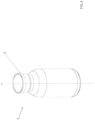
- a container C provided with a cap and with a seal G fastened thereto is shown by way of example in Figure 3 .
- a sealing station is provided in a machine for filling and capping containers.
- a sealing machine meaning a machine that has at least one sealing station.
- the seal can be fed to the containers only once the containers have been positioned on the support plates (not shown).
- the machine 1 also includes a plurality of sealing heads 3, 30 to press a seal G against a cap of a container C when said container is positioned on a support plate 2, and to fasten the seal G on the container C.
- the machine 1 also includes moving means 5 for the support plates 2 to rotate the plates 2 about themselves (i.e. to rotate the containers C about the vertical axis Y of said containers, see Figure 3 ).
- the moving means 5 are designed to rotate the supporting plates 2 independently of each other.
- the machine 1 also includes a detection and control unit 6 (shown schematically in Figures 1 and 2 ) that is designed to detect at least one operating parameter associated with the rotation of each support plate 2 and/or with the compression load between each sealing head 3, 30 and the corresponding seal G, and to compare the value of the detected parameter with a reference value or range of reference values.
- a detection and control unit 6 shown schematically in Figures 1 and 2 .
- the operation carried out by the detection and control unit 6 to detect at least one operating parameter associated with the rotation of each support plate 2 and/or the compression load enables sealing to be optimized (i.e. optimum fastening of a seal G on the related container C).
- the variety of products to be packaged i.e. the types of containers C, caps and seals G, may require different specifications to optimize the sealing operation. Consequently, where the detection and control unit 6 detects that the value of the detected parameter does not match the value of the reference parameter or does not fall within a range of reference values, the actions detailed below can be taken.
- the machine 1 includes further means for sending a signal (for example acoustic and/or visual) (not shown) if the value of the detected parameter is different from the reference value or the range of reference values.
- a signal for example acoustic and/or visual
- the machine 1 can be stopped, or alternatively the rotation of a support plate 2 and/or the compression load between each sealing head 3, 30 and the corresponding seal can be adjusted.
- this operation can be performed manually by an operator or automatically. In this latter case, the machine can be stopped by the detection and control unit 6.
- the machine 1 can also have an adjustment unit 7 (shown schematically in Figures 1 and 2 ) that is connected to the detection and control unit 6 and designed to adjust the rotation of a support plate 2 and/or the compression load between each sealing head 3, 30 and the corresponding seal G if the value of the detected parameter is different from the reference value or the range of reference values.
- an adjustment unit 7 shown schematically in Figures 1 and 2 ) that is connected to the detection and control unit 6 and designed to adjust the rotation of a support plate 2 and/or the compression load between each sealing head 3, 30 and the corresponding seal G if the value of the detected parameter is different from the reference value or the range of reference values.
- the detection and control unit 6 and the adjustment unit 7 can be integral with one another such as to form a single processing unit (not shown).
- the adjustment unit 7 can act on the corresponding electric motor 5 to adjust the rotational speed thereof such as to optimize the sealing operation.
- the moving means 5 are an electric motor 5 (shown partially in Figures 1 and 2 ) for each support plate 2 and the detection and control unit 6 is connected to each electric motor 5.
- each electric motor 5 determines the rotation of each plate 2, i.e. of each container C, determining the rotational speed (or sealing speed) and the number of rotations required to fasten the seal G to the container C (i.e. to complete the sealing operation).
- the adjustment unit 7 acts on the corresponding electric motor 5 to adjust the rotational speed thereof such as to optimize the sealing operation.
- Each sealing head 3, 30 can also have one or more sealing blades 30 that are moveable between an idle position in which said blades are not in contact with the seal G (i.e. are separated from the seal G) of the corresponding container C, and an operating position in which said blades are in contact with the seal G of the corresponding container C, to fasten the seal G to the container C during rotation of the container C.
- Each sealing blade 30 is moved to the related operating position once the container C has been rotated by the related support plate 2.
- the movement of each sealing blade 30 between the two aforementioned positions is driven by cams (not shown).
- each sealing blade 30 can be associated with elastic means (not shown in the attached figures) to prevent overloading during the sealing operation.
- the machine 1 enables the rotational speed of the support plates 2 to be adjusted during the sealing operation, for example by rotating a support plate 2 (and therefore the related container C) at a first speed when the related sealing blade 30 is moved from the related idle position to the operating position, and increasing the rotational speed to a second speed greater than the first speed once the sealing operation has been started. This helps to reduce the particulate matter caused by the blade dragging against the corresponding seal.
- the operating parameter detected by the detection and control unit 6 is the compression load between each sealing head 3, 30 and the corresponding seal G, as explained below.
- each sealing head 3, 30 has an idle stop 3 that is rotatable about itself, to press the seal G against the cap of a container C when said container is placed on a support plate 2.
- Each sealing head 3, 30 can include (or be associated with) a load cell 4.
- the load cell 4 is preferably associated with the idle stop 3 of each sealing head 3, 30.
- the detection and control unit 6 is connected to each load cell 4. The position of the load cell 4 is shown schematically in Figures 1 and 2 .
- the load cell 4 is built into the idle stop 3 (or into a support element thereof) such as to be axially aligned with the container against the cap of the respective container C when said container is positioned on the support plate 2.
- the support plates 2 are also moveable vertically in translation (in opposing directions) to lift the container C towards the related idle stop 3 and to bring each cap of the container C provided with a seal G into contact with the idle stop 3 of the corresponding sealing head 3, 30 (and vice versa) before each support plate 2 is rotated about itself.
- the vertical translational movement of the support plates 2 is cam-driven (not shown).
- each support plate 2 is associated with damping means (also not shown, and preferably comprising a pneumatic piston associated with each support plate 2) to determine the load to be transferred to the container C, i.e. to determine the compression load between each sealing head 3, 30 and the corresponding seal G caused by said vertical translation of the plates 2.
- damping means also not shown, and preferably comprising a pneumatic piston associated with each support plate 2 to determine the load to be transferred to the container C, i.e. to determine the compression load between each sealing head 3, 30 and the corresponding seal G caused by said vertical translation of the plates 2.
- the compression can be adjusted accordingly by acting on the damping means to bring the compression value to an optimum value (within the range of reference values).
- the adjustment unit 7 can be linked to the damping means associated with each plate 2, for example to each piston to adjust the travel thereof.
- the detection and control unit 6 monitors operation of each electric motor 5 (i.e. the related operating parameters) such as to detect a parameter as a function of the current absorbed by each electric motor 5 (which is representative of the compression between the sealing head 3, 30 and the seal G of the container C).
- the detection and control unit 6 detects the power absorbed by each electric motor 5 (which is representative of the absorbed current).
- the adjustment unit 7 can act on the damping means (as mentioned above) to bring the compression value to an optimum value (within the range of reference values).
- the adjustment unit 7 can be linked to the damping means, as described above, associated with each support plate 2.
- the invention also relates to a method for controlling a sealing machine 1 comprising a plurality of support plates 2 that are rotatable about themselves and that each support a container C and a plurality of sealing heads 3, 30 to press the seal G against a container C and to fasten the seal G to the container C.
- the container C is preferably provided with a cap (for example made of rubber or silicone).
- the sealing machine 1 is preferably of the type described above, and reference should be made to the definitions provided above, including in relation to the proposed method.
- the method according to the invention comprises the following steps:
- the machine 1 is also intended to refer to a sealing station in a machine for filling and capping containers.
- a sealing machine meaning a machine that has at least one sealing station.
- the step of rotating the support plates 2 is started by rotating each support plate 2 independently from the other support plates (preferably using an electric motor 5 associated with each plate 2, as described above).
- the method also includes the following steps:
- the step of detecting at least one operating parameter associated with the rotation of each support plate 2 and/or the compression load enables sealing to be optimized (i.e. optimum fastening of a seal G on the related container C).
- the method also includes the step of sending a signal if the value of the detected parameter is different from the reference value or the range of reference values.
- the method includes, after the signal sending step, the step of commanding the machine to stop, or alternatively the step of adjusting the rotation of a support plate 2 and/or the compression load between each sealing head 3, 30 and the corresponding seal G.
- the step of commanding the machine to stop can be done manually (by an operator) or automatically (for example using the aforementioned detection and control device 6).
- the operating parameter detected is the rotation speed of each plate 2 and/or the number of rotations of each support plate 2 required to complete the sealing operation.
- the rotational speed of a plate 2 or the number of rotations to complete the sealing operations is adjusted if the detected parameter is different from the reference value or the range of reference values by acting on the individual plate 2.
- the adjustment step is performed by acting on the individual electric motor 5 that moves the plate 2.
- the electric motor 5 it is also possible to act on the electric motor 5 to adjust the rotational speed of the support plates 2 during the sealing operation, for example by rotating a support plate 2 (and therefore the related container C) at a first speed when the related sealing blade 30 is moved from the related idle position to the operating position, and increasing the rotational speed to a second speed greater than the first speed once the sealing operation has been started. This helps to reduce the particulate matter caused by the blade dragging against the corresponding seal.
- the detected operating parameter is the compression load between each sealing head 3, 30 and the corresponding seal G.
- the compression load can be detected using a load cell 4 associated with each sealing head 3, 30, preferably with the idle stop 3 of each sealing head 3, 30 (or a related support element).
- each support plate 2 can be movable vertically in Translation to move the related container C towards or away from the sealing head 3, 30 and the machine 1 can also have damping means (not shown, each one preferably comprising a pneumatic piston) linked to each support plate 2, to determine the compression load between each sealing head 3, 30 and the corresponding seal G (caused by said vertical translational movement).
- the adjustment step (where present) is performed by adjusting the damping means, preferably by adjusting the travel of each piston.
- the compression load can be detected as a function of the current absorbed by each electric motor 5.
- the current absorbed by each electric motor 5 is representative of the compression load between each sealing head 3, 30 and the corresponding seal.
- the power absorbed by each electric motor 5 can be detected (see above with reference to the sealing machine 1).
- the compression load adjustment step (where present) can be performed by acting on the damping means of the support plates 2 as described above, or by acting on the travel of each piston.
- each product i.e. each product having a given type of container C, cap and seal G
- each product i.e. each product having a given type of container C, cap and seal G
- a predetermined series of mandatory operating parameters thereby creating a genuine ad hoc "recipe" for each product.
Landscapes
- Engineering & Computer Science (AREA)
- Mechanical Engineering (AREA)
- Package Closures (AREA)
- Information Transfer Systems (AREA)
- Electrical Discharge Machining, Electrochemical Machining, And Combined Machining (AREA)
- Container Filling Or Packaging Operations (AREA)
Abstract
- placing capped containers (C) provided with a seal (G) on plates (2),
- rotating the plates (2),
- pressing the seal (G) against the cap of the container (C) and fastening said seal using a sealing head (3, 30).
- detecting at least one parameter associated with the rotation of a plate (2) and/or with the compression load between each sealing head (3, 30) and the seal (G), and
- comparing the value of the parameter with a reference range.
Description
- The present invention pertains to the technical sector of sealing machines.
- More specifically, the present invention relates to a sealing machine and to a method for controlling a sealing machine.
- Automatic machines for capping containers (such as flasks and bottles) that have been filled with a product (liquid or powder) with a cap, usually made of rubber or silicone, are known, for example in the pharmaceutical sector.
- After the capping operation, the containers are conveyed to a sealing machine, having first been provided with a metal capsule referred to as a seal (usually made of aluminum) on the previously applied cap. Said seals are fastened to ensure that each container is closed until the container is opened.
- A known sealing machine has a carousel with a vertical axis and a plurality of individual positions paired with support plates for the capped containers to which the seals will be fastened.
- The carousel includes a plurality of sealing heads arranged above the support plates, each sealing head having an idle stop designed to press the seal against the cap of the container. Each sealing head also has one or more sealing blades that are moveable between an idle position in which said blades are not in contact with the seal of the corresponding container, and an operating position in which said blades are in contact with the seal of the corresponding container, to fasten the seal to the container.
- The support plates are moveable in rotation by common moving means so that each container rotates about its own vertical axis. This enables the sealing blades to act on the entire circumference of the seal, folding the related peripheral edge about the neck of the container. The plates are also moveable vertically in translation to lift the container and to bring each cap of the container into contact with the idle stop of the corresponding sealing head.
- According to an alternative, a sealing station is provided in a machine for filling and capping containers. For the sake of simplicity, reference shall henceforth be made to a sealing machine.
- However, such sealing machines often do not guarantee optimal sealing quality, jeopardizing the safety of the product inside the container. This is also a result of the variety of products to be packaged, i.e. the type of container, cap and seal, that can be fed to the same machine.
- The present invention is therefore intended to resolve the aforementioned drawbacks.
- This objective is achieved by a sealing machine and a method for controlling a sealing machine according to the attached claims.
- Advantageously, the machine and the method according to the invention enable an optimal sealing operation for each container, i.e. said machine and method enable each seal to be optimally fastened to the related container.
- Other advantageous aspects are described in greater detail below with reference to the attached drawings, in which:
-
Figure 1 is a perspective view of a machine according to the invention, -
Figure 2 is a perspective view, different from the view inFigure 1 , of a machine according to the invention, -
Figure 3 is a magnified perspective view of a container provided with a cap and an applied seal. - The sealing machine according to the present invention is indicated with
reference sign 1 inFigures 1 and2 . - The
sealing machine 1 according to the present invention preferably has acarousel 10 that is rotatable about a vertical axis H and that includes a plurality ofsupport plates 2 that are rotatable about themselves and are designed to carry containers C previously provided with a cap (i.e. closed) and seal G (placed on the cap, but not yet fastened). A container C provided with a cap and with a seal G fastened thereto is shown by way of example inFigure 3 . - According to an alternative that is not shown, a sealing station is provided in a machine for filling and capping containers. For the sake of simplicity, reference shall henceforth be made to a sealing machine, meaning a machine that has at least one sealing station.
- According to a further alternative, the seal can be fed to the containers only once the containers have been positioned on the support plates (not shown).
- The
machine 1 also includes a plurality ofsealing heads support plate 2, and to fasten the seal G on the container C. - The
machine 1 also includes moving means 5 for thesupport plates 2 to rotate theplates 2 about themselves (i.e. to rotate the containers C about the vertical axis Y of said containers, seeFigure 3 ). - In particular, the moving
means 5 are designed to rotate the supportingplates 2 independently of each other. - In particular, the
machine 1 also includes a detection and control unit 6 (shown schematically inFigures 1 and2 ) that is designed to detect at least one operating parameter associated with the rotation of eachsupport plate 2 and/or with the compression load between eachsealing head - Advantageously, the operation carried out by the detection and
control unit 6 to detect at least one operating parameter associated with the rotation of eachsupport plate 2 and/or the compression load enables sealing to be optimized (i.e. optimum fastening of a seal G on the related container C). - As mentioned in the introduction to the present document, the variety of products to be packaged, i.e. the types of containers C, caps and seals G, may require different specifications to optimize the sealing operation. Consequently, where the detection and
control unit 6 detects that the value of the detected parameter does not match the value of the reference parameter or does not fall within a range of reference values, the actions detailed below can be taken. - The flow of information between the
sealing machine 1 and the detection andcontrol unit 6 is shown by way of example inFigures 1 and2 using dashed arrows. - According to the preferred embodiment, the
machine 1 includes further means for sending a signal (for example acoustic and/or visual) (not shown) if the value of the detected parameter is different from the reference value or the range of reference values. - In particular, once a signal has been sent, the
machine 1 can be stopped, or alternatively the rotation of asupport plate 2 and/or the compression load between each sealinghead - If the
machine 1 is stopped, this operation can be performed manually by an operator or automatically. In this latter case, the machine can be stopped by the detection andcontrol unit 6. - If alternatively the aforementioned adjustment method is used, the
machine 1 can also have an adjustment unit 7 (shown schematically inFigures 1 and2 ) that is connected to the detection andcontrol unit 6 and designed to adjust the rotation of asupport plate 2 and/or the compression load between eachsealing head - The flow of information between the
sealing machine 1 and the detection andcontrol unit 6 and theadjustment unit 7 is shown by way of example inFigures 1 and2 using dashed arrows. - The detection and
control unit 6 and theadjustment unit 7 can be integral with one another such as to form a single processing unit (not shown). - According to the embodiment described above, if the detection and
control unit 6 detects a parameter associated with aplate 2 that is different from the reference value or the range of reference values, theadjustment unit 7 can act on the correspondingelectric motor 5 to adjust the rotational speed thereof such as to optimize the sealing operation. - According to the preferred embodiment, the moving
means 5 are an electric motor 5 (shown partially inFigures 1 and2 ) for eachsupport plate 2 and the detection andcontrol unit 6 is connected to eachelectric motor 5. In this case, eachelectric motor 5 determines the rotation of eachplate 2, i.e. of each container C, determining the rotational speed (or sealing speed) and the number of rotations required to fasten the seal G to the container C (i.e. to complete the sealing operation). - According to this embodiment, for adjustments in which the detection and
control unit 6 detects a parameter associated with aplate 2 that is different from the reference value or the range of reference values, theadjustment unit 7 acts on the correspondingelectric motor 5 to adjust the rotational speed thereof such as to optimize the sealing operation. - Each sealing
head more sealing blades 30 that are moveable between an idle position in which said blades are not in contact with the seal G (i.e. are separated from the seal G) of the corresponding container C, and an operating position in which said blades are in contact with the seal G of the corresponding container C, to fasten the seal G to the container C during rotation of the container C. Eachsealing blade 30 is moved to the related operating position once the container C has been rotated by therelated support plate 2. Preferably, the movement of eachsealing blade 30 between the two aforementioned positions is driven by cams (not shown). - Preferably, each
sealing blade 30 can be associated with elastic means (not shown in the attached figures) to prevent overloading during the sealing operation. - The
machine 1 according to the invention enables the rotational speed of thesupport plates 2 to be adjusted during the sealing operation, for example by rotating a support plate 2 (and therefore the related container C) at a first speed when therelated sealing blade 30 is moved from the related idle position to the operating position, and increasing the rotational speed to a second speed greater than the first speed once the sealing operation has been started. This helps to reduce the particulate matter caused by the blade dragging against the corresponding seal. - According to one embodiment, the operating parameter detected by the detection and
control unit 6 is the compression load between each sealinghead - Preferably, each sealing
head idle stop 3 that is rotatable about itself, to press the seal G against the cap of a container C when said container is placed on asupport plate 2. Each sealinghead load cell 4. In particular, theload cell 4 is preferably associated with theidle stop 3 of each sealinghead control unit 6 is connected to eachload cell 4. The position of theload cell 4 is shown schematically inFigures 1 and2 . - This makes it possible to determine the compression load between each sealing
head - Preferably, the
load cell 4 is built into the idle stop 3 (or into a support element thereof) such as to be axially aligned with the container against the cap of the respective container C when said container is positioned on thesupport plate 2. - According to the preferred embodiment, the
support plates 2 are also moveable vertically in translation (in opposing directions) to lift the container C towards therelated idle stop 3 and to bring each cap of the container C provided with a seal G into contact with theidle stop 3 of the corresponding sealinghead 3, 30 (and vice versa) before eachsupport plate 2 is rotated about itself. Preferably, the vertical translational movement of thesupport plates 2 is cam-driven (not shown). - Furthermore, each
support plate 2 is associated with damping means (also not shown, and preferably comprising a pneumatic piston associated with each support plate 2) to determine the load to be transferred to the container C, i.e. to determine the compression load between eachsealing head plates 2. - In the adjustment method described above, if the seal G is not being correctly pressed against the corresponding idle stop 3 (and therefore against the cap of the respective container C) during the sealing operations, the compression can be adjusted accordingly by acting on the damping means to bring the compression value to an optimum value (within the range of reference values). In other words, the
adjustment unit 7 can be linked to the damping means associated with eachplate 2, for example to each piston to adjust the travel thereof. - According to one embodiment, the detection and
control unit 6 monitors operation of each electric motor 5 (i.e. the related operating parameters) such as to detect a parameter as a function of the current absorbed by each electric motor 5 (which is representative of the compression between the sealinghead - For example, the detection and
control unit 6 detects the power absorbed by each electric motor 5 (which is representative of the absorbed current). - In this case, where the adjustment method is used, the
adjustment unit 7 can act on the damping means (as mentioned above) to bring the compression value to an optimum value (within the range of reference values). In other words, theadjustment unit 7 can be linked to the damping means, as described above, associated with eachsupport plate 2. - The invention also relates to a method for controlling a sealing
machine 1 comprising a plurality ofsupport plates 2 that are rotatable about themselves and that each support a container C and a plurality of sealingheads - The sealing
machine 1 is preferably of the type described above, and reference should be made to the definitions provided above, including in relation to the proposed method. - The method according to the invention comprises the following steps:
- placing the containers C, preferably already provided with an unfastened seal G, on the
support plates 2, - rotating the
support plates 2, - pressing the seal G against the container C and fastening the seal G to the container C using a sealing
head - As mentioned above, the
machine 1 is also intended to refer to a sealing station in a machine for filling and capping containers. For the sake of simplicity, reference shall henceforth in all cases be made to a sealing machine, meaning a machine that has at least one sealing station. - In particular, the step of rotating the
support plates 2 is started by rotating eachsupport plate 2 independently from the other support plates (preferably using anelectric motor 5 associated with eachplate 2, as described above). - Furthermore, the method also includes the following steps:
- detecting at least one operating parameter associated with the rotation of each
support plate 2 and/or with the compression load between each sealinghead - comparing the value of the at least one detected operating parameter with a reference value or a range of reference values, and
- Advantageously, the step of detecting at least one operating parameter associated with the rotation of each
support plate 2 and/or the compression load enables sealing to be optimized (i.e. optimum fastening of a seal G on the related container C). - According to the preferred embodiment, the method also includes the step of sending a signal if the value of the detected parameter is different from the reference value or the range of reference values.
- According to a possible embodiment, the method includes, after the signal sending step, the step of commanding the machine to stop, or alternatively the step of adjusting the rotation of a
support plate 2 and/or the compression load between each sealinghead - As mentioned above in the description of the
machine 1, the step of commanding the machine to stop can be done manually (by an operator) or automatically (for example using the aforementioned detection and control device 6). - Where there is an adjustment step in response to the detection and
control unit 6 detecting a parameter having a value different from the reference value or range of reference values, optimum sealing of each container C is guaranteed in any case. - According to a preferred embodiment, the operating parameter detected is the rotation speed of each
plate 2 and/or the number of rotations of eachsupport plate 2 required to complete the sealing operation. - In this case, where there is an adjustment step, the rotational speed of a
plate 2 or the number of rotations to complete the sealing operations is adjusted if the detected parameter is different from the reference value or the range of reference values by acting on theindividual plate 2. Preferably, the adjustment step is performed by acting on the individualelectric motor 5 that moves theplate 2. - As mentioned above, it is also possible to act on the
electric motor 5 to adjust the rotational speed of thesupport plates 2 during the sealing operation, for example by rotating a support plate 2 (and therefore the related container C) at a first speed when therelated sealing blade 30 is moved from the related idle position to the operating position, and increasing the rotational speed to a second speed greater than the first speed once the sealing operation has been started. This helps to reduce the particulate matter caused by the blade dragging against the corresponding seal. - According to one embodiment, the detected operating parameter is the compression load between each sealing
head - According to a first variant of this embodiment, the compression load can be detected using a
load cell 4 associated with each sealinghead idle stop 3 of each sealinghead 3, 30 (or a related support element). - As mentioned above, each
support plate 2 can be movable vertically in Translation to move the related container C towards or away from the sealinghead machine 1 can also have damping means (not shown, each one preferably comprising a pneumatic piston) linked to eachsupport plate 2, to determine the compression load between each sealinghead - According to this variant, the adjustment step (where present) is performed by adjusting the damping means, preferably by adjusting the travel of each piston.
- According to an alternative, the compression load can be detected as a function of the current absorbed by each
electric motor 5. The current absorbed by eachelectric motor 5 is representative of the compression load between each sealinghead electric motor 5 can be detected (see above with reference to the sealing machine 1). - Also in this alternative, the compression load adjustment step (where present) can be performed by acting on the damping means of the
support plates 2 as described above, or by acting on the travel of each piston. - The machine and the method according to the invention enable each product (i.e. each product having a given type of container C, cap and seal G) to be associated with a predetermined series of mandatory operating parameters, thereby creating a genuine ad hoc "recipe" for each product.
Claims (10)
- Controlling method of a sealing machine (1), the latter comprising: a plurality of support plates (2) rotatable on themselves each for supporting a container (C) with a cap, and a plurality of sealing heads (3, 30) to keep pressed a seal (G) on a container (C) and fixing the seal (G) to the container (C);the method comprising the steps of:- placing the containers (C) capped and provided with a seal (G) on the support plates (2);- rotating the support plates (2);- keeping pressed the seal (G) to the cap of the container (C) and fixing the seal (G) to the container (C) by means of a sealing head (3, 30);characterized in that:
the step of rotating the support plates (2) is carried out rotating each support plate (2) independently from the others;and in that it comprises the steps of:- - detecting at least one operating parameter associated with the rotation of each support plate (2) and / or with the compression load between each sealing head (3, 30) and the corresponding seal (G); and- comparing the value of at least one operating parameter detected with a reference value or a range of reference values. - The method according to the preceding claim, further comprising the step of:- sending a signal if the value of the detected parameter is different from the reference value or from the range of reference values.
- The method according to the preceding claim, comprising, following the step of sending a signal, the step of:commanding the stop of the machine; or alternatively the phase ofadjusting the rotation of a support plate (2) and / or the compression load between each sealing head (3, 30) and the corresponding seal (G).
- The method according to any of the previous claims, in which the operating parameter detected is the rotation speed of each plate (2) and / or the number of rotations of each support plate (2) necessary to complete the sealing operation.
- The method according to any of the previous claims, in which the detected operating parameter is the compression load between each sealing head (3, 30) and the corresponding seal (G); and in which the step of detecting the compression load is performed by means of a load cell (4) associated with each sealing head (3, 30).
- The method according to any one of the preceding claims 1 to 4, wherein the detected operating parameter is the compression load between each sealing head (3, 30) and the corresponding seal (G); and in which the machine (1) comprises an electric motor (5) associated with each support plate (2);in which step of rotating the support plates (2) takes place by means of each electric motor (5) which is independent from the others;in which step of detecting the compression load is performed by detecting the current absorbed by each electric motor (5).
- Sealing machine (1), comprising:- - a plurality of support plates (2) each rotatable on itself, to support containers (C) with a cap and provided with a seal (G);- a plurality of sealing heads (3, 30) to keep a seal (G) pressed on the cap of a container (C) when this is arranged on a support plate (2) and fix the seal (G) to the container (C);- means (5) for moving the plates (2), for moving the plates (2) in rotation on themselves;characterized in that:the moving means (5) of the support plates (2) are arranged to move the supporting plates (2) in rotation on themselves independently from each other;and in that it comprises:
a detection and control unit (6), designed to detect at least one operating parameter associated with the rotation of each support plate (2) and / or the compression load between each sealing head (3, 30) and the corresponding seal (G) and to compare the detected parameter value with a reference value or range of values. - The machine (1) according to the previous claim, further comprising means for sending a signal, designed to send a signal if the value of the detected parameter is different from the reference value or the range of reference values.
- The machine according to claim 7 or 8, wherein the moving means (5) comprise an electric motor (5) for each support plate (2); each support plate (2) being movable in vertical translation to bring the relative container (C) towards and away from the sealing head (3, 30);
and in which the detection and control unit (6) is connected to each electric motor (5) in order to detect a parameter according to the relative absorbed current. - The machine (1) according to claim 7 or 8, in which each support plate (2) is movable in vertical translation to bring the relative container (C) closer to and away from the sealing head (3, 30); and in which each sealing head (3, 30) comprises an idle stop (3), rotating on itself, to keep a seal (G) pressed on the cap of a container (C) when this is arranged on a support plate (2), and a load cell (4), associated with the idle stop (3); and in which the detection and control unit (6) is connected to each load cell (4).
Applications Claiming Priority (1)
| Application Number | Priority Date | Filing Date | Title |
|---|---|---|---|
| IT102021000026087A IT202100026087A1 (en) | 2021-10-12 | 2021-10-12 | RING RING MACHINE AND RELATED CONTROL METHOD |
Publications (1)
| Publication Number | Publication Date |
|---|---|
| EP4166493A1 true EP4166493A1 (en) | 2023-04-19 |
Family
ID=79018645
Family Applications (1)
| Application Number | Title | Priority Date | Filing Date |
|---|---|---|---|
| EP22200241.2A Pending EP4166493A1 (en) | 2021-10-12 | 2022-10-07 | Sealing machine and related control method |
Country Status (3)
| Country | Link |
|---|---|
| US (1) | US12311429B2 (en) |
| EP (1) | EP4166493A1 (en) |
| IT (1) | IT202100026087A1 (en) |
Families Citing this family (1)
| Publication number | Priority date | Publication date | Assignee | Title |
|---|---|---|---|---|
| KR102800088B1 (en) * | 2022-12-27 | 2025-04-28 | 세메스 주식회사 | apparatus and method for cap automatic fastening |
Citations (4)
| Publication number | Priority date | Publication date | Assignee | Title |
|---|---|---|---|---|
| US5239136A (en) * | 1990-12-07 | 1993-08-24 | Macofar S.P.A. | Pressure adjustment device |
| US7204151B2 (en) * | 2004-05-21 | 2007-04-17 | Shibuya Kogyo Co., Ltd. | Seal load inspection apparatus |
| US8256188B2 (en) * | 2007-04-04 | 2012-09-04 | Robert Bosch Gmbh | Packaging machine |
| EP2923996B1 (en) * | 2014-03-25 | 2016-11-09 | Romaco S.R.L. | Crimping device for a machine for closing containers |
Family Cites Families (4)
| Publication number | Priority date | Publication date | Assignee | Title |
|---|---|---|---|---|
| GB1588106A (en) * | 1978-05-31 | 1981-04-15 | Metal Closures Ltd | Method and apparatusfor securing closures to bottles |
| DE4011398C2 (en) * | 1990-04-09 | 1994-09-22 | Alcoa Gmbh Verpackwerke | Device and method for applying screw caps to containers |
| DE19718631B4 (en) * | 1997-05-02 | 2006-06-14 | Conti Temic Microelectronic Gmbh | Method for controlling the closing operation of a closing device with at least one electromotively moving part |
| JP4232311B2 (en) * | 2000-03-06 | 2009-03-04 | 澁谷工業株式会社 | Capping method and capping device |
-
2021
- 2021-10-12 IT IT102021000026087A patent/IT202100026087A1/en unknown
-
2022
- 2022-10-07 EP EP22200241.2A patent/EP4166493A1/en active Pending
- 2022-10-11 US US17/963,458 patent/US12311429B2/en active Active
Patent Citations (4)
| Publication number | Priority date | Publication date | Assignee | Title |
|---|---|---|---|---|
| US5239136A (en) * | 1990-12-07 | 1993-08-24 | Macofar S.P.A. | Pressure adjustment device |
| US7204151B2 (en) * | 2004-05-21 | 2007-04-17 | Shibuya Kogyo Co., Ltd. | Seal load inspection apparatus |
| US8256188B2 (en) * | 2007-04-04 | 2012-09-04 | Robert Bosch Gmbh | Packaging machine |
| EP2923996B1 (en) * | 2014-03-25 | 2016-11-09 | Romaco S.R.L. | Crimping device for a machine for closing containers |
Also Published As
| Publication number | Publication date |
|---|---|
| US12311429B2 (en) | 2025-05-27 |
| US20230113494A1 (en) | 2023-04-13 |
| IT202100026087A1 (en) | 2023-04-12 |
Similar Documents
| Publication | Publication Date | Title |
|---|---|---|
| US12311429B2 (en) | Sealing machine and related control method | |
| EP2773472B1 (en) | A method to mechanically produce a repeatable seam in a can | |
| US7204151B2 (en) | Seal load inspection apparatus | |
| CN109264650B (en) | Automatic capping machine of shield | |
| CN111977597B (en) | Device for holding a container and closure device | |
| US3338027A (en) | Container sealing apparatus | |
| EP4101808A1 (en) | Automatic container capping machine | |
| KR20210072269A (en) | Turntable rotary type continuos auto capping machine for can | |
| EP3106402B1 (en) | Process and apparatus for closing and printing/labelling a container | |
| US11253905B2 (en) | Spring-loaded knockout pad | |
| EP2923996B1 (en) | Crimping device for a machine for closing containers | |
| JP2020147303A (en) | Capping method and cap wrapping device for tightening the screw cap and container mouth | |
| US20020017076A1 (en) | Turret for bottle capping machine | |
| CN111094170A (en) | Apparatus and method for treating containers with lifting device | |
| CN114789982B (en) | Double-station flange barrel filling machine and filling method | |
| US20230138544A1 (en) | Apparatus for processing containers | |
| JP2001278202A (en) | Bag bottom cradle device in rotary type bag packing machine | |
| JP7464834B2 (en) | Cappa | |
| US20240024946A1 (en) | Control device for sealer | |
| CN212624247U (en) | Divide lid capping mechanism | |
| US20250304420A1 (en) | Apparatus for closing containers and associated operating method | |
| EP3932852B1 (en) | Capping device | |
| CN114772521B (en) | Flange barrel filling machine | |
| EP2016019A2 (en) | Crimping apparatus | |
| CN114789981B (en) | Device capable of ensuring opening and in-situ closing of flange barrel iron hoop |
Legal Events
| Date | Code | Title | Description |
|---|---|---|---|
| PUAI | Public reference made under article 153(3) epc to a published international application that has entered the european phase |
Free format text: ORIGINAL CODE: 0009012 |
|
| STAA | Information on the status of an ep patent application or granted ep patent |
Free format text: STATUS: THE APPLICATION HAS BEEN PUBLISHED |
|
| AK | Designated contracting states |
Kind code of ref document: A1 Designated state(s): AL AT BE BG CH CY CZ DE DK EE ES FI FR GB GR HR HU IE IS IT LI LT LU LV MC ME MK MT NL NO PL PT RO RS SE SI SK SM TR |
|
| P01 | Opt-out of the competence of the unified patent court (upc) registered |
Effective date: 20230524 |
|
| STAA | Information on the status of an ep patent application or granted ep patent |
Free format text: STATUS: REQUEST FOR EXAMINATION WAS MADE |
|
| 17P | Request for examination filed |
Effective date: 20231010 |
|
| RBV | Designated contracting states (corrected) |
Designated state(s): AL AT BE BG CH CY CZ DE DK EE ES FI FR GB GR HR HU IE IS IT LI LT LU LV MC ME MK MT NL NO PL PT RO RS SE SI SK SM TR |