EP4166453A1 - Aircraft electric propulsion system control method - Google Patents
Aircraft electric propulsion system control method Download PDFInfo
- Publication number
- EP4166453A1 EP4166453A1 EP22195762.4A EP22195762A EP4166453A1 EP 4166453 A1 EP4166453 A1 EP 4166453A1 EP 22195762 A EP22195762 A EP 22195762A EP 4166453 A1 EP4166453 A1 EP 4166453A1
- Authority
- EP
- European Patent Office
- Prior art keywords
- propulsion system
- aircraft
- motor
- efficiency
- speed
- Prior art date
- Legal status (The legal status is an assumption and is not a legal conclusion. Google has not performed a legal analysis and makes no representation as to the accuracy of the status listed.)
- Granted
Links
Images




Classifications
-
- B—PERFORMING OPERATIONS; TRANSPORTING
- B64—AIRCRAFT; AVIATION; COSMONAUTICS
- B64C—AEROPLANES; HELICOPTERS
- B64C11/00—Propellers, e.g. of ducted type; Features common to propellers and rotors for rotorcraft
- B64C11/30—Blade pitch-changing mechanisms
- B64C11/303—Blade pitch-changing mechanisms characterised by comprising a governor
-
- B—PERFORMING OPERATIONS; TRANSPORTING
- B64—AIRCRAFT; AVIATION; COSMONAUTICS
- B64C—AEROPLANES; HELICOPTERS
- B64C11/00—Propellers, e.g. of ducted type; Features common to propellers and rotors for rotorcraft
- B64C11/30—Blade pitch-changing mechanisms
- B64C11/305—Blade pitch-changing mechanisms characterised by being influenced by other control systems, e.g. fuel supply
-
- B—PERFORMING OPERATIONS; TRANSPORTING
- B64—AIRCRAFT; AVIATION; COSMONAUTICS
- B64C—AEROPLANES; HELICOPTERS
- B64C11/00—Propellers, e.g. of ducted type; Features common to propellers and rotors for rotorcraft
- B64C11/30—Blade pitch-changing mechanisms
- B64C11/44—Blade pitch-changing mechanisms electric
-
- B—PERFORMING OPERATIONS; TRANSPORTING
- B64—AIRCRAFT; AVIATION; COSMONAUTICS
- B64D—EQUIPMENT FOR FITTING IN OR TO AIRCRAFT; FLIGHT SUITS; PARACHUTES; ARRANGEMENT OR MOUNTING OF POWER PLANTS OR PROPULSION TRANSMISSIONS IN AIRCRAFT
- B64D27/00—Arrangement or mounting of power plants in aircraft; Aircraft characterised by the type or position of power plants
- B64D27/02—Aircraft characterised by the type or position of power plants
- B64D27/30—Aircraft characterised by electric power plants
-
- B—PERFORMING OPERATIONS; TRANSPORTING
- B64—AIRCRAFT; AVIATION; COSMONAUTICS
- B64D—EQUIPMENT FOR FITTING IN OR TO AIRCRAFT; FLIGHT SUITS; PARACHUTES; ARRANGEMENT OR MOUNTING OF POWER PLANTS OR PROPULSION TRANSMISSIONS IN AIRCRAFT
- B64D27/00—Arrangement or mounting of power plants in aircraft; Aircraft characterised by the type or position of power plants
- B64D27/02—Aircraft characterised by the type or position of power plants
- B64D27/30—Aircraft characterised by electric power plants
- B64D27/31—Aircraft characterised by electric power plants within, or attached to, wings
-
- B—PERFORMING OPERATIONS; TRANSPORTING
- B64—AIRCRAFT; AVIATION; COSMONAUTICS
- B64D—EQUIPMENT FOR FITTING IN OR TO AIRCRAFT; FLIGHT SUITS; PARACHUTES; ARRANGEMENT OR MOUNTING OF POWER PLANTS OR PROPULSION TRANSMISSIONS IN AIRCRAFT
- B64D27/00—Arrangement or mounting of power plants in aircraft; Aircraft characterised by the type or position of power plants
- B64D27/02—Aircraft characterised by the type or position of power plants
- B64D27/30—Aircraft characterised by electric power plants
- B64D27/34—All-electric aircraft
-
- B—PERFORMING OPERATIONS; TRANSPORTING
- B64—AIRCRAFT; AVIATION; COSMONAUTICS
- B64D—EQUIPMENT FOR FITTING IN OR TO AIRCRAFT; FLIGHT SUITS; PARACHUTES; ARRANGEMENT OR MOUNTING OF POWER PLANTS OR PROPULSION TRANSMISSIONS IN AIRCRAFT
- B64D27/00—Arrangement or mounting of power plants in aircraft; Aircraft characterised by the type or position of power plants
- B64D27/02—Aircraft characterised by the type or position of power plants
- B64D27/30—Aircraft characterised by electric power plants
- B64D27/35—Arrangements for on-board electric energy production, distribution, recovery or storage
-
- B—PERFORMING OPERATIONS; TRANSPORTING
- B64—AIRCRAFT; AVIATION; COSMONAUTICS
- B64D—EQUIPMENT FOR FITTING IN OR TO AIRCRAFT; FLIGHT SUITS; PARACHUTES; ARRANGEMENT OR MOUNTING OF POWER PLANTS OR PROPULSION TRANSMISSIONS IN AIRCRAFT
- B64D27/00—Arrangement or mounting of power plants in aircraft; Aircraft characterised by the type or position of power plants
- B64D27/02—Aircraft characterised by the type or position of power plants
- B64D27/30—Aircraft characterised by electric power plants
- B64D27/35—Arrangements for on-board electric energy production, distribution, recovery or storage
- B64D27/355—Arrangements for on-board electric energy production, distribution, recovery or storage using fuel cells
-
- B—PERFORMING OPERATIONS; TRANSPORTING
- B64—AIRCRAFT; AVIATION; COSMONAUTICS
- B64D—EQUIPMENT FOR FITTING IN OR TO AIRCRAFT; FLIGHT SUITS; PARACHUTES; ARRANGEMENT OR MOUNTING OF POWER PLANTS OR PROPULSION TRANSMISSIONS IN AIRCRAFT
- B64D31/00—Power plant control systems; Arrangement of power plant control systems in aircraft
- B64D31/02—Initiating means
- B64D31/06—Initiating means actuated automatically
-
- B—PERFORMING OPERATIONS; TRANSPORTING
- B64—AIRCRAFT; AVIATION; COSMONAUTICS
- B64D—EQUIPMENT FOR FITTING IN OR TO AIRCRAFT; FLIGHT SUITS; PARACHUTES; ARRANGEMENT OR MOUNTING OF POWER PLANTS OR PROPULSION TRANSMISSIONS IN AIRCRAFT
- B64D31/00—Power plant control systems; Arrangement of power plant control systems in aircraft
- B64D31/16—Power plant control systems; Arrangement of power plant control systems in aircraft for electric power plants
-
- B—PERFORMING OPERATIONS; TRANSPORTING
- B64—AIRCRAFT; AVIATION; COSMONAUTICS
- B64D—EQUIPMENT FOR FITTING IN OR TO AIRCRAFT; FLIGHT SUITS; PARACHUTES; ARRANGEMENT OR MOUNTING OF POWER PLANTS OR PROPULSION TRANSMISSIONS IN AIRCRAFT
- B64D2221/00—Electric power distribution systems onboard aircraft
-
- Y—GENERAL TAGGING OF NEW TECHNOLOGICAL DEVELOPMENTS; GENERAL TAGGING OF CROSS-SECTIONAL TECHNOLOGIES SPANNING OVER SEVERAL SECTIONS OF THE IPC; TECHNICAL SUBJECTS COVERED BY FORMER USPC CROSS-REFERENCE ART COLLECTIONS [XRACs] AND DIGESTS
- Y02—TECHNOLOGIES OR APPLICATIONS FOR MITIGATION OR ADAPTATION AGAINST CLIMATE CHANGE
- Y02T—CLIMATE CHANGE MITIGATION TECHNOLOGIES RELATED TO TRANSPORTATION
- Y02T50/00—Aeronautics or air transport
- Y02T50/60—Efficient propulsion technologies, e.g. for aircraft
Definitions
- the present disclosure concerns a method of controlling an aircraft electric propulsion system, a controller configured to control an aircraft propulsion system in accordance with the method, and a propulsion system incorporating the control system.
- Electric propulsion systems have been proposed for aircraft, in which one or more electric motors drives one or more propulsors for provided thrust.
- a method of controlling an electric propulsion system of an aircraft comprising:
- the system configured to control the propulsion system to an optimum propulsion system configuration which takes into account both electric motor efficiency and propeller efficiency characteristics, using data available from the aircraft.
- the method may comprise consulting a lookup table which stores either a corresponding governor speed and motor torque set-point or a corresponding motor speed and rotor pitch angle set point for the determined one or more flight parameters.
- the method may comprise inputting aircraft characteristics and flight parameters to an aircraft propulsion system model, and outputting one of the corresponding rotor governor speed and motor torque set-point, and the corresponding motor speed and rotor pitch angle set point.
- the aircraft propulsion system model may comprise one or more of an aircraft drag model, a propeller efficiency model, a motor efficiency model, and a power source efficiency model.
- the one or more aircraft flight parameters may include one or more of an aircraft true airspeed and aircraft equivalent airspeed.
- the method may comprise determining a maximum propulsion system efficiency by calculating a minimum motor input power corresponding to the required thrust.
- the method may comprise determining one or more safety parameters or operational limitations, and outputting rotor governor speed and motor torque set-point which meets these safety parameters or limitations.
- the method may comprise determining one or more of a maximum rotor speed, motor torque, maximum rotor input current and maximum energy storage system output current and maintaining the corresponding rotor governor speed and motor torque set-point below their respective maxima.
- the method may comprise determining one or more energy storage system efficiency parameters, and determining a corresponding rotor governor speed and motor torque set-point which provides the commanded thrust setting at the determined flight parameter with a maximum propulsion system efficiency.
- energy storage efficiency is taken into account when calculating a maximum propulsion system efficiency.
- the method may comprise determining one or more power electronics efficiency parameters, and determining a corresponding rotor governor speed and motor torque set-point which provides the commanded thrust setting at the determined flight parameter with a maximum propulsion system efficiency. Accordingly, power electronics efficiency is taken into account when calculating a maximum propulsion system efficiency.
- a control system for an aircraft electric propulsion system comprising:
- an aircraft propulsion system comprising a control system in accordance with the second aspect.
- the aircraft propulsion system may comprise one or more energy storage units.
- One or more energy storage unit may comprise one or more chemical batteries, one or more fuel cells, or one or more capacitors.
- the aircraft propulsion system may comprise one or more internal combustion engines such as one or more gas turbine engines.
- One or more internal combustion engines may be mechanically coupled to one or more propulsors in a parallel configuration.
- one or more internal combustion engines may be mechanically coupled to one or more electric generators.
- the one or more electric generators may be coupled to one or both of the energy storage units, and one or more electric motor coupled to a propulsor.
- an aircraft comprising a propulsion system in accordance with the third aspect.
- a non-transitory computer storage medium comprising instructions for carrying out the method of the first aspect.
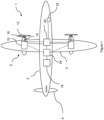
- an aircraft 1 is shown.
- the aircraft is of conventional configuration, having a fuselage 2, wings 3, tail 4 and an electric propulsion system 5.
- the aircraft 1 is an existing airframe which has been adapted for electric propulsion.
- the propulsion system is shown schematically in more detail in figure 2 .
- the propulsion system 5 comprises a propulsion unit on each wing comprising an electric motor 10 mechanically coupled to a propulsor in the form of a propeller 12 via a shaft 14 and propeller pitch change mechanism 16.
- a propulsion unit on each wing comprising an electric motor 10 mechanically coupled to a propulsor in the form of a propeller 12 via a shaft 14 and propeller pitch change mechanism 16.
- the propeller 12 and pitch change mechanism 16 are of conventional construction.
- the propeller pitch change mechanism 16 is configured to alter the pitch of the blades of the propeller 12 (i.e. to change the angle of attack of the blades relative to the oncoming airstream) during flight.
- a reduction gearbox (not shown) may be provided between the shaft 14 and propeller 12, which is configured to reduce the speed of the propeller 12 relative to the motor 10.
- the motor 10 is directly coupled to the propeller 12 via the shaft 14.
- the propulsion system 5 is powered by an energy storage system 18.
- the energy storage system is a hydrogen fuel cell, though other energy storage technologies such as chemical batteries or capacitors could be used instead of or in addition to one or more fuel cells.
- the energy storage system produces electrical power in the form of Direct Current (DC). In some instances, this DC current may be converted to an AC current by one or more power electronics systems 24 in the form of one or more inverters, provided between the energy storage system 18 and motors 10.
- DC Direct Current
- this DC current may be converted to an AC current by one or more power electronics systems 24 in the form of one or more inverters, provided between the energy storage system 18 and motors 10.
- FIG. 2 illustrates the power conversion chain from the energy storage unit 18 to the propeller 12.
- Energy is provided from one or more energy storage units (fuel cell 1 and 2 in figure 2 ), which is provided via power electronics in the form of battery controllers to a main DC bus bar.
- Power from the main DC bus bar is converted to AC power at the required frequency, voltage and current by inverters to respective motors.
- the motors drive respective propellers, to provide propulsive thrust to the aircraft.
- the propulsion system 5 is controlled by a controller 20.
- the controller 20 is in signal communication with the energy storage unit 18, motors 10 and propeller pitch change mechanism 16 and a flight control system 22, and is configured to control at least the motor 10 and pitch change mechanism 16 in response to control inputs from the flight control system 22.
- the controller 20 is typically a digital electronic control system comprising a memory, processing unit and input / outputs, and is of conventional construction.
- the controller 20 comprises control software comprising a look-up table or look-up tables.
- the look-up table is configured to take inputs in the form of at least a thrust demand from the flight control system and one or more flight parameters, such as true or equivalent air speed from an air data system, and correlate these inputs to a corresponding target motor / propeller target parameter pair which provides an optimum (i.e. a computed highest possible) efficiency of the propeller 12 / motor 10 combination.
- Parameter pair 1 Parameter pair 2 Propeller Pitch Angle ⁇ Governor speed ⁇ p Motor Motor Speed ⁇ m Motor Torque ⁇ m
- Each parameter pair represents two degrees of freedom that can be controlled to provide the necessary thrust.
- both options are equally valid and are broadly equivalent - the optimum efficiency can be achieved using either option for a given flight condition.
- parameter pair 2 (governor speed ⁇ p and motor torque ⁇ m ), is that, when installing the system on an existing airframe, the existing propeller speed governor can be utilised without adapting the propeller, or propeller pitch control mechanism. This may make certification more straightforward.
- the parameter pair 1 provides for more direct control of propeller pitch.
- this may also remove transient performance limitations caused by the hydro-mechanical dynamics from the constant speed governor (e.g. slower response due to inertia of counter-weights).
- the controller then controls the actual parameters, such that errors between the target values and a measured or estimated parameter pair are minimised. In one example, this is achieved using a closed loop conventional Proportional, Integral, Derivative (PID) controller.
- PID Proportional, Integral, Derivative
- Alternative control methodologies such as open-loop model-based control may alternatively be used.
- additional propulsion system component efficiencies may be considered by the controller when determining an optimum propulsion system configuration. For example, the efficiency of the inverter may be considered.
- the optimum values for the target parameter pairs can be calculated online by the controller using a propulsion system model, or offline and stored in a lookup table. In either case, the optimum values are calculated by consideration of the airframe drag and component efficiencies of the propulsion system, and an optimum target parameter pair can then be calculated for a desired thrust level for a given airspeed.
- each of the inverter 24, motor, 10 and propeller 12 have respective efficiencies, which will necessarily be less than 100% in each case.
- the inverter will have an efficiency ⁇ l defined by the AC electrical output power in watts divided by the DC electrical input power in watts. Efficiencies below 100% represent thermal losses. This efficiency is typically a function of AC output frequency f and load P.
- the motor will have an efficiency ⁇ m , defined by the useful mechanical output power in watts, divided by the electric input power in watts. This efficiency is typically a function of motor speed ⁇ m and torque ⁇ m for a given motor output power. Since the motor speed ⁇ m is tied to inverter output frequency f, these components do not have separate degrees of freedom, and so the two components can be combined to define a single motor / inverter efficiency metric when considering their efficiencies.
- the propeller 12 will have an efficiency ⁇ p , defined by the useful mechanical output power (thrust) in watts, divided by the mechanical input power in watts. This efficiency is typically a function of rotational speed ⁇ p and pitch angle ⁇ for a given propeller output power. It will be appreciated that, in the case of a directly coupled motor 10 and propeller 12, the propeller rotational speed ⁇ p and motor rotational speed ⁇ m will be equal. Where a gearbox is provided, these speeds will be a fixed multiple of one another, wherein the propeller speed ⁇ p is typically lower than the motor speed ⁇ m .
- the gearbox (where present) also has an efficiency, which may be related to rotational speed. However, since the propeller 12 and gearbox rotate together, these can be treated as a single unit, with a single efficiency metric.
- each of the inverter 24, propeller 16 and motor 10 have an efficiency profile which varies according to various parameters. Each of these factors must be considered and weighted to find an optimum propulsion system configuration.
- FIG. 3 shows an efficiency profile for a combined motor 10 and inverter 24 pair.
- the efficiency profile comprises a graph showing motor torque ⁇ m (which can be measured in newton metres) and motor speed ⁇ m (which can be measured in RPM) and corresponding efficiency isolines (marked as 0.9, 0.8 and 0.7).
- This data can be determined using computer modelling, or experimental testing.
- efficiency varies greatly from around 0.7 (i.e. 70% efficiency) at some speeds and torque settings, to 0.9 (i.e. 90%) at others.
- a given power can be generated by rotating the motor relatively slowly at a high torque, or relatively quickly at a low torque.
- the efficiency at which this power is produced varies considerably, with a complex relationship between motor speed and torque.
- a single torque and speed combination can be defined which provides the necessary power at the highest efficiency.
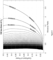
- Figure 4 shows an efficiency profile for a propeller 12 or propeller and gearbox combination.
- the efficiency profile comprises a graph showing the coefficient of power C P of the propeller 12 and advance ratio J, and corresponding efficiency isolines (marked as 0.8, 0.7 and 0.6).
- V TAS is the true airspeed
- N is the rotational speed of the propeller in revolutions per minute
- d is the diameter of the propeller.
- P shaft is shaft input power
- p is the fluid density
- N is the rotational speed of the propeller in revolutions per second
- d is the diameter of the propulsor.
- efficiency varies greatly from around 0.6 (i.e. 60% efficiency) at some advance ratios and coefficients of power, to 0.8 (i.e. 80%) at others.
- a given thrust can be generated by rotating the propeller relatively slowly at a high pitch, or relatively quickly at a low pitch.
- the efficiency at which this thrust is produced varies considerably, with a complex relationship between speed and pitch, which is governed by the relationship between the coefficient of power and the advance ratio.
- a single (or in some cases two) combination can be found, which provides the necessary thrust at the highest efficiency.
- this data can be determined using computer modelling such as CFD, or via wind tunnel testing. Note that the data shown in figure 4 is a subset of contours within the full tabulated data for the propeller 12.
- Figure 5 shows a 3-dimensional graph, relating advance ratio J, coefficient of power C p and propeller pitch angle ⁇ to propeller efficiency.
- propeller efficiency depends strongly on these parameters, with a maximum achievable efficiency given as around 0.8 in this example, but with efficiencies as low as 0.1 also being possible.
- ⁇ p ( J , C p ) is the propeller map from figure 4
- C p ( J , ⁇ ) is the propeller map from figure 5 , but with an inversion of power coefficient and blade angle axes.
- This modified thrust coefficient can be related to the airframe's drag coefficient C D as follows:
- C ′ T ⁇ 8 C D S S prop
- S represents the aircraft wing surface area in square meters
- S prop represents the total propeller reference area in square meters (i.e. propeller disc area, the area swept by the propellers and C D represents the coefficient of drag of the aircraft, as conventionally defined.
- the drag coefficient at a chosen level flight condition airspeed and altitude
- a required modified thrust coefficient for a desired true airspeed, the corresponding iso-thrust coefficient line will capture all points on the propeller performance maps that correspond to the chosen flight condition.
- the following method demonstrates how these iso-lines are used to extract the max overall efficiency points.
- each iso-line of C' T corresponds to a constant equivalent airspeed.
- equation 3 provides a map of thrust coefficient over J and C P , the iso-lines of C' T can be exposed.
- Each iso-line of C' T provides all the possible co-ordinates ( J , C P ) that achieve a given airspeed. It is important to point out that every iso-line will be limited by a physical maximum RPM limit N and minimum RPM N due to stall. This will limit the range of advance ratio J values over which the maximum efficiency search can be performed.
- the set-point generation method includes safety parameters or operational limitations which are excluded from outputs of the optimisation method. Consequently, the set-point generation process includes these limitations, such that set-points that results in exceedance of these limitations are included in the look-up table or model in the controller.
- Examples include propeller and motor speed limits. At greater than a particular speed, damage may occur to either the motor or the propeller, and so maximum values are set for these parameters. Similarly, the propeller may stall below a particular propeller rotational speed, relative airflow velocity or relative airflow angle (angle of attack - ⁇ ), and so limits are set to prevent this. Similarly, depending on the design of the motor 10, the motor may stall at rotational speed below a critical speed, and so a minimum motor speed is also set.
- the motor and / or drivetrain typically have a maximum permissible torque, beyond which damage may occur. Consequently, limits are set to avoid set-points that exceed these limits.
- the motor 10, inverter 24 or energy storage unit 18 may have maximum current limitations, which similarly limit the current that can be drawn. Again, these limitations are included in the model.
- the parameter space can be searched to find a combination of parameters which provides a required thrust for given flight conditions.
- the search method could comprise merely finding a single coordinate on the propeller efficiency map where both the safety limitations and thrust requirements are met.
- the inventors have found that such a method may result in low overall propulsion system efficiency in view of the significant variation in inverter and motor efficiency at different operating points. This is particularly the case where the motor is not well matched to the load.
- the motor efficiency map can be queried along an iso-line knowing the translation (13). Therefore, for each iso-line, the product of propeller and motor efficiency can be found.
- the maximum overall efficiency is denoted ⁇ 0 * , where the superscript * denotes variables at maximum overall efficiency.
- ⁇ m ⁇ * , ⁇ m * is the motor efficiency as a function of motor speed ⁇ and motor torque ⁇ m
- ⁇ p is the propeller efficiency as a function of advance ratio J and the power coefficient C p .
- multiple solutions may exist, i.e. there may exist multiple values of motor speed motor speed ⁇ , motor torque ⁇ m , advance ratio J and the power coefficient C p which provide equally high efficiency.
- a suitable coordinate can be chosen using an additional constraint such as a smallest motor or propeller rotational speed or P shaft .
- a value which is closest to the current value may be selected, to avoid "hunting" behaviour by the propulsion system.
- figure 7 shows a flow chart illustrating the steps required for control of the aircraft propulsion system in accordance with the above computed parameters:
- control scheme can be applied to hybrid aircraft, as well as purely electric aircraft.
- Parallel and series hybrid aircraft have been proposed, in which one or more internal combustion engine is combined with one or more electric motors to drive one or more propulsors.
- Parallel hybrid systems can be distinguished from so-called "series hybrid” systems.
- a parallel hybrid system a mechanical connection is provided by the internal combustion engine and at least one propulsor, with at least one electric motor driving either the same propulsor as that driven by the internal combustion engine, or a further propulsor.
- no mechanical link is provided between the internal combustion system and the propulsors.
- an efficiency map of the gas turbine engine or other internal combustion engine could be considered when determining the maximally efficient operating configuration.
Landscapes
- Engineering & Computer Science (AREA)
- Aviation & Aerospace Engineering (AREA)
- Automation & Control Theory (AREA)
- Electric Propulsion And Braking For Vehicles (AREA)
- Control Of Electric Motors In General (AREA)
Abstract
Description
- The present disclosure concerns a method of controlling an aircraft electric propulsion system, a controller configured to control an aircraft propulsion system in accordance with the method, and a propulsion system incorporating the control system.
- Electric propulsion systems have been proposed for aircraft, in which one or more electric motors drives one or more propulsors for provided thrust.
- According to a first aspect there is provided a method of controlling an electric propulsion system of an aircraft, the propulsion system comprising an electric motor configured to drive a variable pitch propulsor, the method comprising:
- determining a commanded thrust setting;
- determining one or more flight parameters;
- determining either a corresponding rotor governor speed and motor torque set-point, or a corresponding motor speed and rotor pitch angle set point, which provides the commanded thrust setting at the determined flight parameter having a maximum propulsion system efficiency; and
- controlling the rotor governor and electric motor in accordance with the determined respective set-points.
- Advantageously, the system configured to control the propulsion system to an optimum propulsion system configuration which takes into account both electric motor efficiency and propeller efficiency characteristics, using data available from the aircraft.
- The method may comprise consulting a lookup table which stores either a corresponding governor speed and motor torque set-point or a corresponding motor speed and rotor pitch angle set point for the determined one or more flight parameters.
- The method may comprise inputting aircraft characteristics and flight parameters to an aircraft propulsion system model, and outputting one of the corresponding rotor governor speed and motor torque set-point, and the corresponding motor speed and rotor pitch angle set point.
- The aircraft propulsion system model may comprise one or more of an aircraft drag model, a propeller efficiency model, a motor efficiency model, and a power source efficiency model.
- The one or more aircraft flight parameters may include one or more of an aircraft true airspeed and aircraft equivalent airspeed.
- The method may comprise determining a maximum propulsion system efficiency by calculating a minimum motor input power corresponding to the required thrust.
- The method may comprise determining one or more safety parameters or operational limitations, and outputting rotor governor speed and motor torque set-point which meets these safety parameters or limitations. For example, the method may comprise determining one or more of a maximum rotor speed, motor torque, maximum rotor input current and maximum energy storage system output current and maintaining the corresponding rotor governor speed and motor torque set-point below their respective maxima.
- The method may comprise determining one or more energy storage system efficiency parameters, and determining a corresponding rotor governor speed and motor torque set-point which provides the commanded thrust setting at the determined flight parameter with a maximum propulsion system efficiency. Advantageously, energy storage efficiency is taken into account when calculating a maximum propulsion system efficiency.
- The method may comprise determining one or more power electronics efficiency parameters, and determining a corresponding rotor governor speed and motor torque set-point which provides the commanded thrust setting at the determined flight parameter with a maximum propulsion system efficiency. Accordingly, power electronics efficiency is taken into account when calculating a maximum propulsion system efficiency.
- According to a second aspect of the invention there is provided a control system for an aircraft electric propulsion system, the aircraft propulsion system comprising:
- a variable pitch propulsor;
- an electric motor coupled to the variable pitch propulsor; and
- a controller configured to control the variable pitch propulsor and electric motor in accordance with the method of the first aspect.
- According to a third aspect there is provided an aircraft propulsion system comprising a control system in accordance with the second aspect.
- The aircraft propulsion system may comprise one or more energy storage units. One or more energy storage unit may comprise one or more chemical batteries, one or more fuel cells, or one or more capacitors.
- The aircraft propulsion system may comprise one or more internal combustion engines such as one or more gas turbine engines. One or more internal combustion engines may be mechanically coupled to one or more propulsors in a parallel configuration. Alternatively or in addition, one or more internal combustion engines may be mechanically coupled to one or more electric generators. The one or more electric generators may be coupled to one or both of the energy storage units, and one or more electric motor coupled to a propulsor.
- According to a fourth aspect there is provided an aircraft comprising a propulsion system in accordance with the third aspect.
- According to a fifth aspect there is provided a non-transitory computer storage medium comprising instructions for carrying out the method of the first aspect.
- The skilled person will appreciate that except where mutually exclusive, a feature described in relation to any one of the above aspects may be applied mutatis mutandis to any other aspect. Furthermore except where mutually exclusive any feature described herein may be applied to any aspect and/or combined with any other feature described herein.
- An embodiment will now be described by way of example only, with reference to the Figures, in which:
-
Figure 1 is a plan view of a first aircraft comprising an electric propulsion system; -
Figure 2 is a schematic diagram of an electric propulsion system for the aircraft offigure 1 ; -
Figure 3 is a graph showing an efficiency map for an inverter and motor combination of the electric propulsion system offigure 2 as a function of torque and motor rotational speeds; -
Figure 4 is a graph showing an efficiency map for a propeller of the electric propulsion system offigure 2 as a function of coefficient of power and advance ratio; -
Figure 5 is a graph illustrating modified coefficient of thrust C'T as a function of coefficient of power and advance ratio; -
Figure 6 is a flow diagram illustrating a method of calculating an online model or look-up table correlating airspeed and desired thrust with a maximally efficient propulsion system configuration; and -
Figure 7 is a flow diagram illustrating a method of control of the electric propulsion system offigure 2 according to the look-up table or model calculating in accordance with the method offigure 6 . - With reference to
Figure 1 , anaircraft 1 is shown. The aircraft is of conventional configuration, having afuselage 2,wings 3,tail 4 and anelectric propulsion system 5. Indeed, in some embodiments, theaircraft 1 is an existing airframe which has been adapted for electric propulsion. The propulsion system is shown schematically in more detail infigure 2 . - The
propulsion system 5 comprises a propulsion unit on each wing comprising anelectric motor 10 mechanically coupled to a propulsor in the form of apropeller 12 via ashaft 14 and propellerpitch change mechanism 16. As will be appreciated, other forms of propulsor such as ducted fans could also be used. Thepropeller 12 andpitch change mechanism 16 are of conventional construction. The propellerpitch change mechanism 16 is configured to alter the pitch of the blades of the propeller 12 (i.e. to change the angle of attack of the blades relative to the oncoming airstream) during flight. In some cases, a reduction gearbox (not shown) may be provided between theshaft 14 andpropeller 12, which is configured to reduce the speed of thepropeller 12 relative to themotor 10. In other cases, themotor 10 is directly coupled to thepropeller 12 via theshaft 14. - The
propulsion system 5 is powered by anenergy storage system 18. In the present embodiment, the energy storage system is a hydrogen fuel cell, though other energy storage technologies such as chemical batteries or capacitors could be used instead of or in addition to one or more fuel cells. The energy storage system produces electrical power in the form of Direct Current (DC). In some instances, this DC current may be converted to an AC current by one or morepower electronics systems 24 in the form of one or more inverters, provided between theenergy storage system 18 andmotors 10. -
Figure 2 illustrates the power conversion chain from theenergy storage unit 18 to thepropeller 12. Energy is provided from one or more energy storage units (fuel cell figure 2 ), which is provided via power electronics in the form of battery controllers to a main DC bus bar. Power from the main DC bus bar is converted to AC power at the required frequency, voltage and current by inverters to respective motors. The motors drive respective propellers, to provide propulsive thrust to the aircraft. - Referring again to
figure 1 , thepropulsion system 5 is controlled by acontroller 20. Thecontroller 20 is in signal communication with theenergy storage unit 18,motors 10 and propellerpitch change mechanism 16 and aflight control system 22, and is configured to control at least themotor 10 andpitch change mechanism 16 in response to control inputs from theflight control system 22. - The
controller 20 is typically a digital electronic control system comprising a memory, processing unit and input / outputs, and is of conventional construction. Thecontroller 20 comprises control software comprising a look-up table or look-up tables. The look-up table is configured to take inputs in the form of at least a thrust demand from the flight control system and one or more flight parameters, such as true or equivalent air speed from an air data system, and correlate these inputs to a corresponding target motor / propeller target parameter pair which provides an optimum (i.e. a computed highest possible) efficiency of thepropeller 12 /motor 10 combination. These parameter pairs comprise either a corresponding target motor speed Ωm and target pitch angle β for thepitch change mechanism 16 for the associatedpropeller 12, or a corresponding governor speed set-point Ωp and target motor torque τm for themotors 10, as shown in the below table:Parameter pair 1Parameter pair 2Propeller Pitch Angle β Governor speed Ωp Motor Motor Speed Ωm Motor Torque τm - Each parameter pair represents two degrees of freedom that can be controlled to provide the necessary thrust. For steady state operation of the propulsion system, both options are equally valid and are broadly equivalent - the optimum efficiency can be achieved using either option for a given flight condition. There are however advantages and disadvantages of controlling the system in accordance with each of these methods.
- An advantage of using parameter pair 2 (governor speed Ωp and motor torque τm), is that, when installing the system on an existing airframe, the existing propeller speed governor can be utilised without adapting the propeller, or propeller pitch control mechanism. This may make certification more straightforward. On the other hand, the
parameter pair 1 provides for more direct control of propeller pitch. - By removing the constant speed governor, this may also remove transient performance limitations caused by the hydro-mechanical dynamics from the constant speed governor (e.g. slower response due to inertia of counter-weights).
- Once a target parameter pair is derived, either from the propulsion system model or the lookup table, the controller then controls the actual parameters, such that errors between the target values and a measured or estimated parameter pair are minimised. In one example, this is achieved using a closed loop conventional Proportional, Integral, Derivative (PID) controller. Alternative control methodologies such as open-loop model-based control may alternatively be used. Optionally, additional propulsion system component efficiencies may be considered by the controller when determining an optimum propulsion system configuration. For example, the efficiency of the inverter may be considered.
- The optimum values for the target parameter pairs can be calculated online by the controller using a propulsion system model, or offline and stored in a lookup table. In either case, the optimum values are calculated by consideration of the airframe drag and component efficiencies of the propulsion system, and an optimum target parameter pair can then be calculated for a desired thrust level for a given airspeed.
- Referring again to
figure 2 , each of theinverter 24, motor, 10 andpropeller 12 have respective efficiencies, which will necessarily be less than 100% in each case. For example, the inverter will have an efficiency ηl defined by the AC electrical output power in watts divided by the DC electrical input power in watts. Efficiencies below 100% represent thermal losses. This efficiency is typically a function of AC output frequency f and load P. Similarly, the motor will have an efficiency ηm, defined by the useful mechanical output power in watts, divided by the electric input power in watts. This efficiency is typically a function of motor speed Ωm and torque τm for a given motor output power. Since the motor speed Ωm is tied to inverter output frequency f, these components do not have separate degrees of freedom, and so the two components can be combined to define a single motor / inverter efficiency metric when considering their efficiencies. - Similarly, the
propeller 12 will have an efficiency ηp, defined by the useful mechanical output power (thrust) in watts, divided by the mechanical input power in watts. This efficiency is typically a function of rotational speed Ωp and pitch angle β for a given propeller output power. It will be appreciated that, in the case of a directly coupledmotor 10 andpropeller 12, the propeller rotational speed Ωp and motor rotational speed Ωm will be equal. Where a gearbox is provided, these speeds will be a fixed multiple of one another, wherein the propeller speed Ωp is typically lower than the motor speed Ωm. The gearbox (where present) also has an efficiency, which may be related to rotational speed. However, since thepropeller 12 and gearbox rotate together, these can be treated as a single unit, with a single efficiency metric. - Consequently, each of the
inverter 24,propeller 16 andmotor 10 have an efficiency profile which varies according to various parameters. Each of these factors must be considered and weighted to find an optimum propulsion system configuration. -
Figure 3 shows an efficiency profile for a combinedmotor 10 andinverter 24 pair. The efficiency profile comprises a graph showing motor torque τm (which can be measured in newton metres) and motor speed Ωm (which can be measured in RPM) and corresponding efficiency isolines (marked as 0.9, 0.8 and 0.7). This data can be determined using computer modelling, or experimental testing. As can be seen, efficiency varies greatly from around 0.7 (i.e. 70% efficiency) at some speeds and torque settings, to 0.9 (i.e. 90%) at others. In principle, a given power can be generated by rotating the motor relatively slowly at a high torque, or relatively quickly at a low torque. However, the efficiency at which this power is produced varies considerably, with a complex relationship between motor speed and torque. In general however, a single torque and speed combination can be defined which provides the necessary power at the highest efficiency. -
Figure 4 shows an efficiency profile for apropeller 12 or propeller and gearbox combination. Again, the efficiency profile comprises a graph showing the coefficient of power CP of thepropeller 12 and advance ratio J, and corresponding efficiency isolines (marked as 0.8, 0.7 and 0.6). - The advance ratio J is a non-dimensional number given by the following well-known equation:

- Where VTAS is the true airspeed, N is the rotational speed of the propeller in revolutions per minute, and d is the diameter of the propeller. An interesting result of this research is that the correct configuration for propulsion system overall maximum efficiency can be calculated from true airspeed, rather than indicated airspeed, or any other flight parameter. This is because the propeller efficiency depends on advance ratio, which is a function of the actual relative velocity of airflow over the propeller due to aircraft forward motion (true airspeed), rather than dynamic pressure (indicated airspeed). In some cases, true airspeed may be calculated from equivalent airspeed or any other airspeed which is available using the aircraft air data sensors.
- Similarly, the propeller power coefficient CP is given by the following well-known equation:

- Where Pshaft is shaft input power, p is the fluid density, N is the rotational speed of the propeller in revolutions per second, and d is the diameter of the propulsor.
- As can be seen, efficiency varies greatly from around 0.6 (i.e. 60% efficiency) at some advance ratios and coefficients of power, to 0.8 (i.e. 80%) at others. In principle, a given thrust can be generated by rotating the propeller relatively slowly at a high pitch, or relatively quickly at a low pitch. However, the efficiency at which this thrust is produced varies considerably, with a complex relationship between speed and pitch, which is governed by the relationship between the coefficient of power and the advance ratio. In general however, a single (or in some cases two) combination can be found, which provides the necessary thrust at the highest efficiency. Again, this data can be determined using computer modelling such as CFD, or via wind tunnel testing. Note that the data shown in
figure 4 is a subset of contours within the full tabulated data for thepropeller 12. -
Figure 5 shows a 3-dimensional graph, relating advance ratio J, coefficient of power Cp and propeller pitch angle β to propeller efficiency. Again, as can be seen, propeller efficiency depends strongly on these parameters, with a maximum achievable efficiency given as around 0.8 in this example, but with efficiencies as low as 0.1 also being possible. - In order to calculate the look-up table or online model defining the most efficient propulsion system configuration for given flight conditions, a set-point generation scheme is defined.
- Initially, a modified thrust coefficient C'T is defined as:

- Where ηp (J,Cp ) is the propeller map from
figure 4 , and Cp (J,β) is the propeller map fromfigure 5 , but with an inversion of power coefficient and blade angle axes. - This modified thrust coefficient can be related to the airframe's drag coefficient CD as follows:

- Where S represents the aircraft wing surface area in square meters, Sprop represents the total propeller reference area in square meters (i.e. propeller disc area, the area swept by the propellers and CD represents the coefficient of drag of the aircraft, as conventionally defined.
- The drag coefficient at a chosen level flight condition (airspeed and altitude) can be translated to a required modified thrust coefficient. Hence, for a desired true airspeed, the corresponding iso-thrust coefficient line will capture all points on the propeller performance maps that correspond to the chosen flight condition. The following method demonstrates how these iso-lines are used to extract the max overall efficiency points.
- For steady-state flight conditions, each iso-line of C'T corresponds to a constant equivalent airspeed. For simplicity, the following considers sea-level conditions, where equivalent and true airspeed are interchangeable. Since
equation 3 provides a map of thrust coefficient over J and CP , the iso-lines of C'T can be exposed. Each iso-line of C'T provides all the possible co-ordinates (J,CP ) that achieve a given airspeed. It is important to point out that every iso-line will be limited by a physical maximum RPM limit N and minimum RPM N due to stall. This will limit the range of advance ratio J values over which the maximum efficiency search can be performed. - In practice therefore, the set-point generation method includes safety parameters or operational limitations which are excluded from outputs of the optimisation method. Consequently, the set-point generation process includes these limitations, such that set-points that results in exceedance of these limitations are included in the look-up table or model in the controller.
- Examples include propeller and motor speed limits. At greater than a particular speed, damage may occur to either the motor or the propeller, and so maximum values are set for these parameters. Similarly, the propeller may stall below a particular propeller rotational speed, relative airflow velocity or relative airflow angle (angle of attack - α), and so limits are set to prevent this. Similarly, depending on the design of the
motor 10, the motor may stall at rotational speed below a critical speed, and so a minimum motor speed is also set. - Other limitations may apply to various components. For example, the motor and / or drivetrain (such as
shaft 14 and gearbox where present) typically have a maximum permissible torque, beyond which damage may occur. Consequently, limits are set to avoid set-points that exceed these limits. Themotor 10,inverter 24 orenergy storage unit 18 may have maximum current limitations, which similarly limit the current that can be drawn. Again, these limitations are included in the model. - Once these limitations are included, the parameter space can be searched to find a combination of parameters which provides a required thrust for given flight conditions.
- If only the propeller efficiency were to be considered, the search method could comprise merely finding a single coordinate on the propeller efficiency map where both the safety limitations and thrust requirements are met. However, the inventors have found that such a method may result in low overall propulsion system efficiency in view of the significant variation in inverter and motor efficiency at different operating points. This is particularly the case where the motor is not well matched to the load.
- However, by using the fact that a modified thrust coefficient iso-line corresponds to a constant equivalent airspeed, all co-ordinates (J, Cp ) for the iso-line can be translated into equivalent motor speed and torque coordinates; to query the EPU efficiency map, a translation according to
equation 5 is performed:
- The translation is performed using equation (1) re-arranged for N, and the following relationship between torque and power coefficient:

- This gives a relationship between advance ratio J and coefficient of power Cp, and modified coefficient of thrust C't.
- Now, for a given airspeed, the motor efficiency map can be queried along an iso-line knowing the translation (13). Therefore, for each iso-line, the product of propeller and motor efficiency can be found. The maximum overall efficiency is denoted

overall efficiency 

- Where

- In some cases, multiple solutions may exist, i.e. there may exist multiple values of motor speed motor speed Ω, motor torque τm , advance ratio J and the power coefficient Cp which provide equally high efficiency. In such a case, a suitable coordinate can be chosen using an additional constraint such as a smallest motor or propeller rotational speed or Pshaft. Alternatively, a value which is closest to the current value may be selected, to avoid "hunting" behaviour by the propulsion system.
- Consequently, a method can be defined for calculating the look-up table or online model, which relates current airspeed and desired thrust to corresponding motor and propulsor configurations which generate a maximum propulsion system efficiency. Such a method is illustrated in the flow diagram in
figure 6 , and comprises the following steps: - 1. Generate a range of steady-state equivalent true airspeeds over which the airframe is to fly at. This can be derived from a consideration of aircraft performance (speed and altitude) capability, which may in turn be determined from parameters such as thrust and drag, as well as likely atmospheric conditions such as temperatures.
- 2. For each airspeed:
- a. Compute the drag coefficient CD of the aircraft;
- b. Compute the modified thrust coefficient C'T (from equation 4);
- c. Obtain the set of co-ordinates J, CP that correspond to the iso-line of C'T, using the map generated from
equation 3; - d. Limit the range of co-ordinates J, CP to account for safety parameters and operational limitations to produce an allowable range of parameters;
- e. Compute the overall efficiency by querying propeller and motor / inverter maps for the allowable parameters of J and Cp ; and
- f. Select the coordinate (i.e. motor and propulsor parameters) the for max overall efficiency, yielding

- Consequently, knowing

- Similarly,
figure 7 shows a flow chart illustrating the steps required for control of the aircraft propulsion system in accordance with the above computed parameters: - 1. Determine the true airspeed and commanded thrust, through communication with aircraft air data sensors and pilot or autopilot input;
- 2. Determine target set points for motor and propulsor parameters to yield the thrust at the highest possible propulsion system efficiency, utilising the lookup table generated in accordance with the method shown in
figure 6 ; and - 3. Control the propulsion system to minimise error between the set-points and the actual parameters.
- By operating the aircraft to this maximum efficient configuration, the aircraft performance is significantly improved. The inventors have found that efficiency improvements of around 2% can be realised by operating the propulsion system in accordance with the above method. Such an improvement is significant in the field of electric aircraft, in view of the large weight and low energy density of electric energy storage systems. For example, a 2% reduction in energy usage may correspond to a greater than 2% increase in range, in view of the logarithmic relationship between aircraft energy storage capacity and resultant range.
- Variations of the above described arrangement can be envisaged. For example, the control scheme can be applied to hybrid aircraft, as well as purely electric aircraft.
- Parallel and series hybrid aircraft have been proposed, in which one or more internal combustion engine is combined with one or more electric motors to drive one or more propulsors. Parallel hybrid systems can be distinguished from so-called "series hybrid" systems. In a parallel hybrid system, a mechanical connection is provided by the internal combustion engine and at least one propulsor, with at least one electric motor driving either the same propulsor as that driven by the internal combustion engine, or a further propulsor. In a series system, no mechanical link is provided between the internal combustion system and the propulsors.
- In such a case, an efficiency map of the gas turbine engine or other internal combustion engine could be considered when determining the maximally efficient operating configuration.
- It will be understood that the invention is not limited to the embodiments above-described and various modifications and improvements can be made without departing from the concepts described herein. Except where mutually exclusive, any of the features may be employed separately or in combination with any other features and the disclosure extends to and includes all combinations and subcombinations of one or more features described herein.
Claims (15)
- A method of controlling an electric propulsion system (5) of an aircraft (1), the propulsion system comprising an electric motor (10) configured to drive a variable pitch propulsor (12), the method comprising:determining a commanded thrust setting;determining one or more flight parameters;determining either a corresponding rotor governor speed and motor torque set-point, or a corresponding motor speed and rotor pitch angle set point, which provides the commanded thrust setting at the determined flight parameter having a maximum propulsion system efficiency; andcontrolling the rotor governor and electric motor in accordance with the determined respective set-points.
- A method according to claim 1, wherein the method comprises consulting a lookup table which stores either a corresponding governor speed and motor torque set-point or a corresponding motor speed and rotor pitch angle set point for the determined one or more flight parameters.
- A method according to claim 1, wherein the method comprises inputting aircraft characteristics and flight parameters to an aircraft propulsion system model, and outputting one of the corresponding rotor governor speed and motor torque set-point, and the corresponding motor speed and rotor pitch angle set point.
- A method according to claim 3, wherein the aircraft propulsion system model comprised one or more of an aircraft drag model, a propeller efficiency model, a motor efficiency model, and a power source efficiency model.
- A method according to any of the preceding claims, wherein the one or more aircraft flight parameters includes one or more of an aircraft true airspeed and aircraft equivalent airspeed.
- A method according to any of the preceding claims, wherein the method comprises determining a maximum propulsion system efficiency by calculating a minimum motor input power corresponding to the required thrust
- A method according to any of the preceding claims, wherein the method comprises determining one or more safety parameters or operational limitations, and outputting rotor governor speed and motor torque set-point which meets these safety parameters or limitations.
- A method according to claim 7, wherein the method comprises determining one or more of a maximum rotor speed, motor torque, maximum rotor input current and maximum energy storage system output current and maintaining the corresponding rotor governor speed and motor torque set-point below their respective maxima.
- A method according to any of the preceding claims, wherein the method comprises determining one or more energy storage system efficiency parameters, and determining a corresponding rotor governor speed and motor torque set-point which provides the commanded thrust setting at the determined flight parameter with a maximum propulsion system efficiency.
- A method according to any of the preceding claims, wherein the method comprises determining one or more power electronics efficiency parameters, and determining a corresponding rotor governor speed and motor torque set-point which provides the commanded thrust setting at the determined flight parameter with a maximum propulsion system efficiency.
- A control system for an aircraft electric propulsion system, the aircraft propulsion system comprising:a variable pitch propulsor;an electric motor coupled to the variable pitch propulsor; anda controller configured to control the variable pitch propulsor and electric motor in accordance with the method of any of the preceding claims.
- An aircraft propulsion system comprising a control system in accordance with claim 11.
- An aircraft propulsion system according to claim 12, wherein the aircraft propulsion system comprises one or more energy storage units.
- An aircraft propulsion system according to claim 12 or claim 13, wherein the aircraft propulsion system comprises one or more internal combustion engines such as one or more gas turbine engines.
- An aircraft comprising a propulsion system in accordance with any of claims 11 to 14.
Applications Claiming Priority (1)
| Application Number | Priority Date | Filing Date | Title |
|---|---|---|---|
| GBGB2114747.5A GB202114747D0 (en) | 2021-10-15 | 2021-10-15 | Aircraft electric propulsion system control method |
Publications (2)
| Publication Number | Publication Date |
|---|---|
| EP4166453A1 true EP4166453A1 (en) | 2023-04-19 |
| EP4166453B1 EP4166453B1 (en) | 2024-07-17 |
Family
ID=78718466
Family Applications (1)
| Application Number | Title | Priority Date | Filing Date |
|---|---|---|---|
| EP22195762.4A Active EP4166453B1 (en) | 2021-10-15 | 2022-09-15 | Aircraft electric propulsion system control method |
Country Status (3)
| Country | Link |
|---|---|
| US (1) | US20230122557A1 (en) |
| EP (1) | EP4166453B1 (en) |
| GB (1) | GB202114747D0 (en) |
Cited By (1)
| Publication number | Priority date | Publication date | Assignee | Title |
|---|---|---|---|---|
| EP4699936A3 (en) * | 2024-08-19 | 2026-03-18 | Pratt & Whitney Canada Corp. | Measuring efficiency in an electric power system for an aircraft propulsion system |
Families Citing this family (2)
| Publication number | Priority date | Publication date | Assignee | Title |
|---|---|---|---|---|
| US20240375767A1 (en) * | 2023-05-09 | 2024-11-14 | Pipistrel D.O.O. | Peak Efficiency Propeller Control |
| US12509217B2 (en) * | 2023-09-13 | 2025-12-30 | Pipistrel D.O.O. | Direct thrust control method for aircraft thruster |
Citations (5)
| Publication number | Priority date | Publication date | Assignee | Title |
|---|---|---|---|---|
| EP2691297A1 (en) * | 2011-03-31 | 2014-02-05 | BAE Systems Plc. | Propeller operation |
| WO2014158240A2 (en) * | 2013-03-14 | 2014-10-02 | Rolls-Royce Corporation | Hybrid turbo electric aero-propulsion system control |
| US20200140062A1 (en) * | 2018-11-01 | 2020-05-07 | Eviation Tech Ltd | Electric propeller and ducted fan propulsion unit |
| WO2020240567A1 (en) * | 2019-05-28 | 2020-12-03 | Eviation Aircraft Ltd. | Thrust control system and method |
| US11128251B1 (en) * | 2020-04-29 | 2021-09-21 | The Boeing Company | Fault-tolerant power system architecture for aircraft electric propulsion |
-
2021
- 2021-10-15 GB GBGB2114747.5A patent/GB202114747D0/en not_active Ceased
-
2022
- 2022-09-15 EP EP22195762.4A patent/EP4166453B1/en active Active
- 2022-09-23 US US17/934,657 patent/US20230122557A1/en not_active Abandoned
Patent Citations (5)
| Publication number | Priority date | Publication date | Assignee | Title |
|---|---|---|---|---|
| EP2691297A1 (en) * | 2011-03-31 | 2014-02-05 | BAE Systems Plc. | Propeller operation |
| WO2014158240A2 (en) * | 2013-03-14 | 2014-10-02 | Rolls-Royce Corporation | Hybrid turbo electric aero-propulsion system control |
| US20200140062A1 (en) * | 2018-11-01 | 2020-05-07 | Eviation Tech Ltd | Electric propeller and ducted fan propulsion unit |
| WO2020240567A1 (en) * | 2019-05-28 | 2020-12-03 | Eviation Aircraft Ltd. | Thrust control system and method |
| US11128251B1 (en) * | 2020-04-29 | 2021-09-21 | The Boeing Company | Fault-tolerant power system architecture for aircraft electric propulsion |
Cited By (1)
| Publication number | Priority date | Publication date | Assignee | Title |
|---|---|---|---|---|
| EP4699936A3 (en) * | 2024-08-19 | 2026-03-18 | Pratt & Whitney Canada Corp. | Measuring efficiency in an electric power system for an aircraft propulsion system |
Also Published As
| Publication number | Publication date |
|---|---|
| EP4166453B1 (en) | 2024-07-17 |
| GB202114747D0 (en) | 2021-12-01 |
| US20230122557A1 (en) | 2023-04-20 |
Similar Documents
| Publication | Publication Date | Title |
|---|---|---|
| US20230122557A1 (en) | Aircraft electric propulsion system control method | |
| EP2971594B1 (en) | Hybrid turbo electric aero-propulsion system control | |
| RU2638883C2 (en) | Engine control device | |
| EP3360781B1 (en) | Dual functon aircraft | |
| EP3964438B1 (en) | Hybrid aircraft propulsion system | |
| CA3009027C (en) | Propulsion system for an aircraft | |
| CN110844089A (en) | Feedforward Load Sensing for Hybrid Electric Systems | |
| CN111186584B (en) | hybrid aircraft | |
| CN114861314A (en) | Energy optimization configuration method and device for airplane hybrid electric propulsion system | |
| JP2020069975A (en) | Hybrid air vehicle | |
| CN105173092A (en) | Hybrid power multi-shaft rotor wing unmanned aerial vehicle | |
| US12263953B2 (en) | System and method for operating a hybrid aircraft power plant | |
| EP3895993B1 (en) | Charging scheme for electric propulsion systems | |
| EP4253246A1 (en) | Aircraft powerplant(s) for an aircraft with electric machine controlled propulsor speed | |
| Laskaridis | Assessment of distributed propulsion systems used with different aircraft configurations | |
| Bai et al. | Optimization and Experimental Validation of Energy Management and Control for a Distributed Hybrid Electric Propulsion Aircraft | |
| KR101375945B1 (en) | Apparatus and method for pitch angle controlling of turbine by using fuzzy rule | |
| JPH0323399B2 (en) | ||
| Hnidka et al. | Calculation of the maximum endurance of a small unmanned aerial vehicle in a hover | |
| Lee et al. | Enhanced calibration and performance prediction method for entire propulsion system of eVTOL UAV | |
| US20240067347A1 (en) | Aircrafts, systems, and methods for providing constant torque on takeoff | |
| Hoyos et al. | Improvement of electric aircraft endurance through propeller optimization via BEM-CFD methodology | |
| AL-Hussainy et al. | Smart adaptive control of an air pressure tank driven by an efficient DC driver | |
| Johnsen et al. | Integration of a 7-KW Turboelectric Power System in a Vertical Take-Off and Landing Unmanned Aircraft | |
| CN119378143B (en) | A method for controlling the speed of a propfan engine |
Legal Events
| Date | Code | Title | Description |
|---|---|---|---|
| PUAI | Public reference made under article 153(3) epc to a published international application that has entered the european phase |
Free format text: ORIGINAL CODE: 0009012 |
|
| STAA | Information on the status of an ep patent application or granted ep patent |
Free format text: STATUS: THE APPLICATION HAS BEEN PUBLISHED |
|
| AK | Designated contracting states |
Kind code of ref document: A1 Designated state(s): AL AT BE BG CH CY CZ DE DK EE ES FI FR GB GR HR HU IE IS IT LI LT LU LV MC MK MT NL NO PL PT RO RS SE SI SK SM TR |
|
| STAA | Information on the status of an ep patent application or granted ep patent |
Free format text: STATUS: REQUEST FOR EXAMINATION WAS MADE |
|
| 17P | Request for examination filed |
Effective date: 20230621 |
|
| RBV | Designated contracting states (corrected) |
Designated state(s): AL AT BE BG CH CY CZ DE DK EE ES FI FR GB GR HR HU IE IS IT LI LT LU LV MC MK MT NL NO PL PT RO RS SE SI SK SM TR |
|
| GRAP | Despatch of communication of intention to grant a patent |
Free format text: ORIGINAL CODE: EPIDOSNIGR1 |
|
| STAA | Information on the status of an ep patent application or granted ep patent |
Free format text: STATUS: GRANT OF PATENT IS INTENDED |
|
| GRAS | Grant fee paid |
Free format text: ORIGINAL CODE: EPIDOSNIGR3 |
|
| INTG | Intention to grant announced |
Effective date: 20240514 |
|
| GRAA | (expected) grant |
Free format text: ORIGINAL CODE: 0009210 |
|
| STAA | Information on the status of an ep patent application or granted ep patent |
Free format text: STATUS: THE PATENT HAS BEEN GRANTED |
|
| P01 | Opt-out of the competence of the unified patent court (upc) registered |
Effective date: 20240515 |
|
| AK | Designated contracting states |
Kind code of ref document: B1 Designated state(s): AL AT BE BG CH CY CZ DE DK EE ES FI FR GB GR HR HU IE IS IT LI LT LU LV MC MK MT NL NO PL PT RO RS SE SI SK SM TR |
|
| REG | Reference to a national code |
Ref country code: CH Ref legal event code: EP |
|
| REG | Reference to a national code |
Ref country code: DE Ref legal event code: R096 Ref document number: 602022004592 Country of ref document: DE |
|
| REG | Reference to a national code |
Ref country code: IE Ref legal event code: FG4D |
|
| REG | Reference to a national code |
Ref country code: LT Ref legal event code: MG9D |
|
| REG | Reference to a national code |
Ref country code: NL Ref legal event code: MP Effective date: 20240717 |
|
| PG25 | Lapsed in a contracting state [announced via postgrant information from national office to epo] |
Ref country code: PT Free format text: LAPSE BECAUSE OF FAILURE TO SUBMIT A TRANSLATION OF THE DESCRIPTION OR TO PAY THE FEE WITHIN THE PRESCRIBED TIME-LIMIT Effective date: 20241118 |
|
| REG | Reference to a national code |
Ref country code: AT Ref legal event code: MK05 Ref document number: 1703896 Country of ref document: AT Kind code of ref document: T Effective date: 20240717 |
|
| PG25 | Lapsed in a contracting state [announced via postgrant information from national office to epo] |
Ref country code: NL Free format text: LAPSE BECAUSE OF FAILURE TO SUBMIT A TRANSLATION OF THE DESCRIPTION OR TO PAY THE FEE WITHIN THE PRESCRIBED TIME-LIMIT Effective date: 20240717 |
|
| PG25 | Lapsed in a contracting state [announced via postgrant information from national office to epo] |
Ref country code: PT Free format text: LAPSE BECAUSE OF FAILURE TO SUBMIT A TRANSLATION OF THE DESCRIPTION OR TO PAY THE FEE WITHIN THE PRESCRIBED TIME-LIMIT Effective date: 20241118 Ref country code: NL Free format text: LAPSE BECAUSE OF FAILURE TO SUBMIT A TRANSLATION OF THE DESCRIPTION OR TO PAY THE FEE WITHIN THE PRESCRIBED TIME-LIMIT Effective date: 20240717 |
|
| PG25 | Lapsed in a contracting state [announced via postgrant information from national office to epo] |
Ref country code: NO Free format text: LAPSE BECAUSE OF FAILURE TO SUBMIT A TRANSLATION OF THE DESCRIPTION OR TO PAY THE FEE WITHIN THE PRESCRIBED TIME-LIMIT Effective date: 20241017 |
|
| PG25 | Lapsed in a contracting state [announced via postgrant information from national office to epo] |
Ref country code: GR Free format text: LAPSE BECAUSE OF FAILURE TO SUBMIT A TRANSLATION OF THE DESCRIPTION OR TO PAY THE FEE WITHIN THE PRESCRIBED TIME-LIMIT Effective date: 20241018 Ref country code: FI Free format text: LAPSE BECAUSE OF FAILURE TO SUBMIT A TRANSLATION OF THE DESCRIPTION OR TO PAY THE FEE WITHIN THE PRESCRIBED TIME-LIMIT Effective date: 20240717 Ref country code: PL Free format text: LAPSE BECAUSE OF FAILURE TO SUBMIT A TRANSLATION OF THE DESCRIPTION OR TO PAY THE FEE WITHIN THE PRESCRIBED TIME-LIMIT Effective date: 20240717 |
|
| PG25 | Lapsed in a contracting state [announced via postgrant information from national office to epo] |
Ref country code: BG Free format text: LAPSE BECAUSE OF FAILURE TO SUBMIT A TRANSLATION OF THE DESCRIPTION OR TO PAY THE FEE WITHIN THE PRESCRIBED TIME-LIMIT Effective date: 20240717 |
|
| PG25 | Lapsed in a contracting state [announced via postgrant information from national office to epo] |
Ref country code: LV Free format text: LAPSE BECAUSE OF FAILURE TO SUBMIT A TRANSLATION OF THE DESCRIPTION OR TO PAY THE FEE WITHIN THE PRESCRIBED TIME-LIMIT Effective date: 20240717 |
|
| PG25 | Lapsed in a contracting state [announced via postgrant information from national office to epo] |
Ref country code: AT Free format text: LAPSE BECAUSE OF FAILURE TO SUBMIT A TRANSLATION OF THE DESCRIPTION OR TO PAY THE FEE WITHIN THE PRESCRIBED TIME-LIMIT Effective date: 20240717 Ref country code: IS Free format text: LAPSE BECAUSE OF FAILURE TO SUBMIT A TRANSLATION OF THE DESCRIPTION OR TO PAY THE FEE WITHIN THE PRESCRIBED TIME-LIMIT Effective date: 20241117 |
|
| PG25 | Lapsed in a contracting state [announced via postgrant information from national office to epo] |
Ref country code: HR Free format text: LAPSE BECAUSE OF FAILURE TO SUBMIT A TRANSLATION OF THE DESCRIPTION OR TO PAY THE FEE WITHIN THE PRESCRIBED TIME-LIMIT Effective date: 20240717 |
|
| PG25 | Lapsed in a contracting state [announced via postgrant information from national office to epo] |
Ref country code: RS Free format text: LAPSE BECAUSE OF FAILURE TO SUBMIT A TRANSLATION OF THE DESCRIPTION OR TO PAY THE FEE WITHIN THE PRESCRIBED TIME-LIMIT Effective date: 20241017 Ref country code: ES Free format text: LAPSE BECAUSE OF FAILURE TO SUBMIT A TRANSLATION OF THE DESCRIPTION OR TO PAY THE FEE WITHIN THE PRESCRIBED TIME-LIMIT Effective date: 20240717 |
|
| PG25 | Lapsed in a contracting state [announced via postgrant information from national office to epo] |
Ref country code: RS Free format text: LAPSE BECAUSE OF FAILURE TO SUBMIT A TRANSLATION OF THE DESCRIPTION OR TO PAY THE FEE WITHIN THE PRESCRIBED TIME-LIMIT Effective date: 20241017 Ref country code: PL Free format text: LAPSE BECAUSE OF FAILURE TO SUBMIT A TRANSLATION OF THE DESCRIPTION OR TO PAY THE FEE WITHIN THE PRESCRIBED TIME-LIMIT Effective date: 20240717 Ref country code: NO Free format text: LAPSE BECAUSE OF FAILURE TO SUBMIT A TRANSLATION OF THE DESCRIPTION OR TO PAY THE FEE WITHIN THE PRESCRIBED TIME-LIMIT Effective date: 20241017 Ref country code: LV Free format text: LAPSE BECAUSE OF FAILURE TO SUBMIT A TRANSLATION OF THE DESCRIPTION OR TO PAY THE FEE WITHIN THE PRESCRIBED TIME-LIMIT Effective date: 20240717 Ref country code: IS Free format text: LAPSE BECAUSE OF FAILURE TO SUBMIT A TRANSLATION OF THE DESCRIPTION OR TO PAY THE FEE WITHIN THE PRESCRIBED TIME-LIMIT Effective date: 20241117 Ref country code: HR Free format text: LAPSE BECAUSE OF FAILURE TO SUBMIT A TRANSLATION OF THE DESCRIPTION OR TO PAY THE FEE WITHIN THE PRESCRIBED TIME-LIMIT Effective date: 20240717 Ref country code: GR Free format text: LAPSE BECAUSE OF FAILURE TO SUBMIT A TRANSLATION OF THE DESCRIPTION OR TO PAY THE FEE WITHIN THE PRESCRIBED TIME-LIMIT Effective date: 20241018 Ref country code: FI Free format text: LAPSE BECAUSE OF FAILURE TO SUBMIT A TRANSLATION OF THE DESCRIPTION OR TO PAY THE FEE WITHIN THE PRESCRIBED TIME-LIMIT Effective date: 20240717 Ref country code: ES Free format text: LAPSE BECAUSE OF FAILURE TO SUBMIT A TRANSLATION OF THE DESCRIPTION OR TO PAY THE FEE WITHIN THE PRESCRIBED TIME-LIMIT Effective date: 20240717 Ref country code: BG Free format text: LAPSE BECAUSE OF FAILURE TO SUBMIT A TRANSLATION OF THE DESCRIPTION OR TO PAY THE FEE WITHIN THE PRESCRIBED TIME-LIMIT Effective date: 20240717 Ref country code: AT Free format text: LAPSE BECAUSE OF FAILURE TO SUBMIT A TRANSLATION OF THE DESCRIPTION OR TO PAY THE FEE WITHIN THE PRESCRIBED TIME-LIMIT Effective date: 20240717 |
|
| PG25 | Lapsed in a contracting state [announced via postgrant information from national office to epo] |
Ref country code: RO Free format text: LAPSE BECAUSE OF FAILURE TO SUBMIT A TRANSLATION OF THE DESCRIPTION OR TO PAY THE FEE WITHIN THE PRESCRIBED TIME-LIMIT Effective date: 20240717 Ref country code: DK Free format text: LAPSE BECAUSE OF FAILURE TO SUBMIT A TRANSLATION OF THE DESCRIPTION OR TO PAY THE FEE WITHIN THE PRESCRIBED TIME-LIMIT Effective date: 20240717 Ref country code: SM Free format text: LAPSE BECAUSE OF FAILURE TO SUBMIT A TRANSLATION OF THE DESCRIPTION OR TO PAY THE FEE WITHIN THE PRESCRIBED TIME-LIMIT Effective date: 20240717 |
|
| REG | Reference to a national code |
Ref country code: DE Ref legal event code: R097 Ref document number: 602022004592 Country of ref document: DE |
|
| PG25 | Lapsed in a contracting state [announced via postgrant information from national office to epo] |
Ref country code: MC Free format text: LAPSE BECAUSE OF FAILURE TO SUBMIT A TRANSLATION OF THE DESCRIPTION OR TO PAY THE FEE WITHIN THE PRESCRIBED TIME-LIMIT Effective date: 20240717 Ref country code: EE Free format text: LAPSE BECAUSE OF FAILURE TO SUBMIT A TRANSLATION OF THE DESCRIPTION OR TO PAY THE FEE WITHIN THE PRESCRIBED TIME-LIMIT Effective date: 20240717 |
|
| PG25 | Lapsed in a contracting state [announced via postgrant information from national office to epo] |
Ref country code: CZ Free format text: LAPSE BECAUSE OF FAILURE TO SUBMIT A TRANSLATION OF THE DESCRIPTION OR TO PAY THE FEE WITHIN THE PRESCRIBED TIME-LIMIT Effective date: 20240717 |
|
| PG25 | Lapsed in a contracting state [announced via postgrant information from national office to epo] |
Ref country code: SK Free format text: LAPSE BECAUSE OF FAILURE TO SUBMIT A TRANSLATION OF THE DESCRIPTION OR TO PAY THE FEE WITHIN THE PRESCRIBED TIME-LIMIT Effective date: 20240717 |
|
| PG25 | Lapsed in a contracting state [announced via postgrant information from national office to epo] |
Ref country code: LU Free format text: LAPSE BECAUSE OF NON-PAYMENT OF DUE FEES Effective date: 20240915 |
|
| PLBE | No opposition filed within time limit |
Free format text: ORIGINAL CODE: 0009261 |
|
| STAA | Information on the status of an ep patent application or granted ep patent |
Free format text: STATUS: NO OPPOSITION FILED WITHIN TIME LIMIT |
|
| 26N | No opposition filed |
Effective date: 20250422 |
|
| REG | Reference to a national code |
Ref country code: BE Ref legal event code: MM Effective date: 20240930 |
|
| PG25 | Lapsed in a contracting state [announced via postgrant information from national office to epo] |
Ref country code: BE Free format text: LAPSE BECAUSE OF NON-PAYMENT OF DUE FEES Effective date: 20240930 |
|
| PG25 | Lapsed in a contracting state [announced via postgrant information from national office to epo] |
Ref country code: IE Free format text: LAPSE BECAUSE OF NON-PAYMENT OF DUE FEES Effective date: 20240915 |
|
| PG25 | Lapsed in a contracting state [announced via postgrant information from national office to epo] |
Ref country code: SE Free format text: LAPSE BECAUSE OF FAILURE TO SUBMIT A TRANSLATION OF THE DESCRIPTION OR TO PAY THE FEE WITHIN THE PRESCRIBED TIME-LIMIT Effective date: 20240717 |
|
| PGFP | Annual fee paid to national office [announced via postgrant information from national office to epo] |
Ref country code: DE Payment date: 20250926 Year of fee payment: 4 |
|
| PGFP | Annual fee paid to national office [announced via postgrant information from national office to epo] |
Ref country code: FR Payment date: 20250925 Year of fee payment: 4 |
|
| PG25 | Lapsed in a contracting state [announced via postgrant information from national office to epo] |
Ref country code: CY Free format text: LAPSE BECAUSE OF FAILURE TO SUBMIT A TRANSLATION OF THE DESCRIPTION OR TO PAY THE FEE WITHIN THE PRESCRIBED TIME-LIMIT; INVALID AB INITIO Effective date: 20220915 Ref country code: IT Free format text: LAPSE BECAUSE OF FAILURE TO SUBMIT A TRANSLATION OF THE DESCRIPTION OR TO PAY THE FEE WITHIN THE PRESCRIBED TIME-LIMIT Effective date: 20240717 |
|
| PG25 | Lapsed in a contracting state [announced via postgrant information from national office to epo] |
Ref country code: HU Free format text: LAPSE BECAUSE OF FAILURE TO SUBMIT A TRANSLATION OF THE DESCRIPTION OR TO PAY THE FEE WITHIN THE PRESCRIBED TIME-LIMIT; INVALID AB INITIO Effective date: 20220915 |
|
| REG | Reference to a national code |
Ref country code: CH Ref legal event code: H13 Free format text: ST27 STATUS EVENT CODE: U-0-0-H10-H13 (AS PROVIDED BY THE NATIONAL OFFICE) Effective date: 20260504 |