EP4166404A1 - Systeme und verfahren zur steuerung einer externen bremskühlvorrichtung gemäss flugzeug und bremszustand - Google Patents
Systeme und verfahren zur steuerung einer externen bremskühlvorrichtung gemäss flugzeug und bremszustand Download PDFInfo
- Publication number
- EP4166404A1 EP4166404A1 EP22196204.6A EP22196204A EP4166404A1 EP 4166404 A1 EP4166404 A1 EP 4166404A1 EP 22196204 A EP22196204 A EP 22196204A EP 4166404 A1 EP4166404 A1 EP 4166404A1
- Authority
- EP
- European Patent Office
- Prior art keywords
- aircraft
- cooling apparatus
- brake
- temperature
- controller
- Prior art date
- Legal status (The legal status is an assumption and is not a legal conclusion. Google has not performed a legal analysis and makes no representation as to the accuracy of the status listed.)
- Pending
Links
- 238000001816 cooling Methods 0.000 title claims abstract description 188
- 238000000034 method Methods 0.000 title claims description 28
- 238000004891 communication Methods 0.000 claims abstract description 32
- 238000005259 measurement Methods 0.000 description 8
- OKTJSMMVPCPJKN-UHFFFAOYSA-N Carbon Chemical compound [C] OKTJSMMVPCPJKN-UHFFFAOYSA-N 0.000 description 6
- 230000008901 benefit Effects 0.000 description 6
- 229910052799 carbon Inorganic materials 0.000 description 6
- 230000001276 controlling effect Effects 0.000 description 5
- 230000015654 memory Effects 0.000 description 5
- 230000008878 coupling Effects 0.000 description 4
- 238000010168 coupling process Methods 0.000 description 4
- 238000005859 coupling reaction Methods 0.000 description 4
- 238000010586 diagram Methods 0.000 description 4
- 239000000463 material Substances 0.000 description 4
- 230000006870 function Effects 0.000 description 3
- 230000001965 increasing effect Effects 0.000 description 3
- 230000008569 process Effects 0.000 description 3
- 230000000712 assembly Effects 0.000 description 2
- 238000000429 assembly Methods 0.000 description 2
- 238000009529 body temperature measurement Methods 0.000 description 2
- 230000001939 inductive effect Effects 0.000 description 2
- 238000013021 overheating Methods 0.000 description 2
- 238000012545 processing Methods 0.000 description 2
- 230000001105 regulatory effect Effects 0.000 description 2
- RZVHIXYEVGDQDX-UHFFFAOYSA-N 9,10-anthraquinone Chemical compound C1=CC=C2C(=O)C3=CC=CC=C3C(=O)C2=C1 RZVHIXYEVGDQDX-UHFFFAOYSA-N 0.000 description 1
- 240000002989 Euphorbia neriifolia Species 0.000 description 1
- 230000003213 activating effect Effects 0.000 description 1
- 230000006978 adaptation Effects 0.000 description 1
- 230000033228 biological regulation Effects 0.000 description 1
- 230000001010 compromised effect Effects 0.000 description 1
- 238000010276 construction Methods 0.000 description 1
- 230000007423 decrease Effects 0.000 description 1
- 238000013461 design Methods 0.000 description 1
- 230000005672 electromagnetic field Effects 0.000 description 1
- 230000007613 environmental effect Effects 0.000 description 1
- 239000000446 fuel Substances 0.000 description 1
- 230000003862 health status Effects 0.000 description 1
- 238000010438 heat treatment Methods 0.000 description 1
- 238000009434 installation Methods 0.000 description 1
- 239000007788 liquid Substances 0.000 description 1
- 238000013178 mathematical model Methods 0.000 description 1
- 230000007246 mechanism Effects 0.000 description 1
- 238000012544 monitoring process Methods 0.000 description 1
- 238000005457 optimization Methods 0.000 description 1
- 230000000737 periodic effect Effects 0.000 description 1
Images


Classifications
-
- B—PERFORMING OPERATIONS; TRANSPORTING
- B60—VEHICLES IN GENERAL
- B60T—VEHICLE BRAKE CONTROL SYSTEMS OR PARTS THEREOF; BRAKE CONTROL SYSTEMS OR PARTS THEREOF, IN GENERAL; ARRANGEMENT OF BRAKING ELEMENTS ON VEHICLES IN GENERAL; PORTABLE DEVICES FOR PREVENTING UNWANTED MOVEMENT OF VEHICLES; VEHICLE MODIFICATIONS TO FACILITATE COOLING OF BRAKES
- B60T17/00—Component parts, details, or accessories of power brake systems not covered by groups B60T8/00, B60T13/00 or B60T15/00, or presenting other characteristic features
- B60T17/18—Safety devices; Monitoring
- B60T17/22—Devices for monitoring or checking brake systems; Signal devices
- B60T17/221—Procedure or apparatus for checking or keeping in a correct functioning condition of brake systems
-
- F—MECHANICAL ENGINEERING; LIGHTING; HEATING; WEAPONS; BLASTING
- F16—ENGINEERING ELEMENTS AND UNITS; GENERAL MEASURES FOR PRODUCING AND MAINTAINING EFFECTIVE FUNCTIONING OF MACHINES OR INSTALLATIONS; THERMAL INSULATION IN GENERAL
- F16D—COUPLINGS FOR TRANSMITTING ROTATION; CLUTCHES; BRAKES
- F16D65/00—Parts or details
- F16D65/78—Features relating to cooling
- F16D65/84—Features relating to cooling for disc brakes
- F16D65/847—Features relating to cooling for disc brakes with open cooling system, e.g. cooled by air
-
- B—PERFORMING OPERATIONS; TRANSPORTING
- B64—AIRCRAFT; AVIATION; COSMONAUTICS
- B64C—AEROPLANES; HELICOPTERS
- B64C25/00—Alighting gear
- B64C25/32—Alighting gear characterised by elements which contact the ground or similar surface
- B64C25/42—Arrangement or adaptation of brakes
-
- B—PERFORMING OPERATIONS; TRANSPORTING
- B64—AIRCRAFT; AVIATION; COSMONAUTICS
- B64F—GROUND OR AIRCRAFT-CARRIER-DECK INSTALLATIONS SPECIALLY ADAPTED FOR USE IN CONNECTION WITH AIRCRAFT; DESIGNING, MANUFACTURING, ASSEMBLING, CLEANING, MAINTAINING OR REPAIRING AIRCRAFT, NOT OTHERWISE PROVIDED FOR; HANDLING, TRANSPORTING, TESTING OR INSPECTING AIRCRAFT COMPONENTS, NOT OTHERWISE PROVIDED FOR
- B64F5/00—Designing, manufacturing, assembling, cleaning, maintaining or repairing aircraft, not otherwise provided for; Handling, transporting, testing or inspecting aircraft components, not otherwise provided for
- B64F5/60—Testing or inspecting aircraft components or systems
-
- F—MECHANICAL ENGINEERING; LIGHTING; HEATING; WEAPONS; BLASTING
- F16—ENGINEERING ELEMENTS AND UNITS; GENERAL MEASURES FOR PRODUCING AND MAINTAINING EFFECTIVE FUNCTIONING OF MACHINES OR INSTALLATIONS; THERMAL INSULATION IN GENERAL
- F16D—COUPLINGS FOR TRANSMITTING ROTATION; CLUTCHES; BRAKES
- F16D65/00—Parts or details
- F16D65/78—Features relating to cooling
-
- F—MECHANICAL ENGINEERING; LIGHTING; HEATING; WEAPONS; BLASTING
- F16—ENGINEERING ELEMENTS AND UNITS; GENERAL MEASURES FOR PRODUCING AND MAINTAINING EFFECTIVE FUNCTIONING OF MACHINES OR INSTALLATIONS; THERMAL INSULATION IN GENERAL
- F16D—COUPLINGS FOR TRANSMITTING ROTATION; CLUTCHES; BRAKES
- F16D66/00—Arrangements for monitoring working conditions, e.g. wear, temperature
- F16D66/02—Apparatus for indicating wear
- F16D66/021—Apparatus for indicating wear using electrical detection or indication means
-
- F—MECHANICAL ENGINEERING; LIGHTING; HEATING; WEAPONS; BLASTING
- F16—ENGINEERING ELEMENTS AND UNITS; GENERAL MEASURES FOR PRODUCING AND MAINTAINING EFFECTIVE FUNCTIONING OF MACHINES OR INSTALLATIONS; THERMAL INSULATION IN GENERAL
- F16D—COUPLINGS FOR TRANSMITTING ROTATION; CLUTCHES; BRAKES
- F16D65/00—Parts or details
- F16D65/78—Features relating to cooling
- F16D2065/783—Features relating to cooling cooling control or adjustment
-
- F—MECHANICAL ENGINEERING; LIGHTING; HEATING; WEAPONS; BLASTING
- F16—ENGINEERING ELEMENTS AND UNITS; GENERAL MEASURES FOR PRODUCING AND MAINTAINING EFFECTIVE FUNCTIONING OF MACHINES OR INSTALLATIONS; THERMAL INSULATION IN GENERAL
- F16D—COUPLINGS FOR TRANSMITTING ROTATION; CLUTCHES; BRAKES
- F16D65/00—Parts or details
- F16D65/78—Features relating to cooling
- F16D2065/787—Pumps
-
- F—MECHANICAL ENGINEERING; LIGHTING; HEATING; WEAPONS; BLASTING
- F16—ENGINEERING ELEMENTS AND UNITS; GENERAL MEASURES FOR PRODUCING AND MAINTAINING EFFECTIVE FUNCTIONING OF MACHINES OR INSTALLATIONS; THERMAL INSULATION IN GENERAL
- F16D—COUPLINGS FOR TRANSMITTING ROTATION; CLUTCHES; BRAKES
- F16D66/00—Arrangements for monitoring working conditions, e.g. wear, temperature
- F16D2066/001—Temperature
Definitions
- the arrangements disclosed herein relate to cooling systems for brakes. More specifically, they relate to systems and methods for aircraft brake cooling.
- Brakes such as in aircraft or other vehicles or machines comprise components that can become hot during use. This heat can cause damage or wear to the brake components and thus affect the effectiveness of the brakes.
- Cooling systems are known to cool or prevent overheating of the brake components. Conventional cooling systems are controlled e.g. using a simple on/off control such as manual switching on and off cooling fans by the pilot or ground crew.
- an aircraft brake cooling system comprising a temperature sensor disposed onboard an aircraft and configured to measure a temperature data of an aircraft brake, a controller in electronic communication with the temperature sensor, and an external cooling apparatus configured to provide cooling to the aircraft brake.
- the controller is in electronic communication with the external cooling apparatus.
- the controller is configured to receive the temperature data from the temperature sensor.
- the controller is configured to send a cooling apparatus control signal to the external cooling apparatus based upon the temperature of the brake.
- the controller is disposed onboard the aircraft.
- the external cooling apparatus is located externally from the aircraft and the controller is disposed on the cooling apparatus.
- the controller is further configured to receive aircraft data from an avionics unit, the aircraft data indicative of an expected departure time of the aircraft, and the controller is configured to send the cooling apparatus control signal to the external cooling apparatus further based upon the expected departure time of the aircraft.
- the aircraft data is further indicative of an estimated taxi duration of the aircraft, and the controller is configured to send the cooling apparatus control signal to the external cooling apparatus further based upon the estimated taxi duration of the aircraft.
- the external cooling apparatus comprises a fan.
- the controller is further configured to obtain a wear rate profile for the aircraft brake indicative of wear rate in dependence on temperature.
- the controller is configured to send the cooling apparatus control signal to the external cooling apparatus based upon both the temperature data of the aircraft brake and the wear rate profile.
- the wear rate profile includes a maximum wear rate temperature value T_WEAR_MAX, being a temperature at which the wear rate is at a maximum, the controller further configured to compare the brake temperature with the maximum wear rate temperature value, and send the cooling apparatus control signal to the external cooling apparatus further based upon a result of the comparison.
- the controller is configured to activate the external cooling apparatus if the brake temperature is less than the maximum wear rate temperature and the controller is configured to not activate the external cooling apparatus if the brake temperature is not less than the maximum wear rate temperature but is less than a predetermined maximum temperature value.
- a method for cooling an aircraft brake comprising receiving, with a control unit, a measured temperature of the aircraft brake, receiving, with the control unit, a plurality of aircraft parameter, generating, with the control unit, a cooling apparatus control signal based upon the measured temperature and the plurality of aircraft parameters, and sending, by the control unit, the cooling apparatus control signal to an external brake cooling apparatus, wherein the external brake cooling apparatus is disposed externally from an aircraft.
- the aircraft data is indicative of a time before departure. In various embodiments, the aircraft data is indicative of an expected taxi duration. In various embodiments, the method further comprises receiving, with the control unit, a wear rate profile for the aircraft brake indicative of wear rate in dependence on temperature. In various embodiments, the method further comprises generating, with the control unit, the cooling apparatus control signal based upon the wear rate profile. In various embodiments, the wear rate profile includes a maximum wear rate temperature value T_WEAR_MAX, being a temperature at which the wear rate is at a maximum, and the method further comprises comparing, with the control unit, the measured temperature with the maximum wear rate temperature value, and generating, with the control unit, the cooling apparatus control signal further based upon a result of the comparison.
- T_WEAR_MAX maximum wear rate temperature value
- an external cooling apparatus for an aircraft brake comprising a controller configured to receive data from an aircraft, wherein the controller is configured to control operation of the external cooling apparatus based upon the data received from the aircraft.
- the controller is configured to receive updated data from the aircraft as the external cooling apparatus provides cooling to the aircraft brake.
- the external cooling apparatus is located externally from the aircraft and the controller is disposed onboard the external cooling apparatus.
- the external cooling apparatus comprises a fan.
- the data is indicative of at least one of an expected departure time of the aircraft, an estimated taxi duration of the aircraft, and a temperature of the aircraft brake.
- the controller is configured to communicate with the aircraft via a wireless communication channel.
- the controller is configured to obtain a wear rate profile for the aircraft brake indicative of wear rate in dependence on temperature, and the controller is configured to control operation of the external cooling apparatus based upon a temperature of the aircraft brake and the wear rate profile.
- systems, methods, and devices for brake cooling such as with an external cooling fan. While numerous details are included herein pertaining to aircraft components, such as brake components, the systems and methods disclosed herein can be applied to other systems with brakes and the like.
- electro communication means communication of electronic signals with physical coupling (e.g., “electrical communication” or “electrically coupled”) or without physical coupling and via an electromagnetic field (e.g., “inductive communication” or “inductively coupled” or “inductive coupling”).
- electromagnetic field e.g., “inductive communication” or “inductively coupled” or “inductive coupling”
- electroconductive communication includes wired and wireless communications (e.g., Bluetooth, TCP/IP, Wi-Fi, etc.).
- Aircraft brakes may be cooled through fans, which can be either installed in the brake assembly or can be available on ground at the gate and are activated by an airport operator during parking.
- the second option is often preferred by airlines, since the installation of fans in the brake assemblies increase the aircraft weight with consequent increase in the fuel burn.
- Brake cooling systems and methods include an external cooling apparatus, such as a fan, controlled by the aircraft avionics, in accordance with various embodiments (e.g., see FIG. 2 ).
- the cooling apparatus control algorithm for the cooling apparatus may be executed by the aircraft avionics, for instance by the brake control unit (BCU).
- BCU brake control unit
- the BCU collects the information for the control algorithm and computes a control signal that is sent to the external cooling apparatus for regulating the external cooling apparatus, in accordance with various embodiments.
- the present disclosure provides an external cooling apparatus capable of receiving information from the aircraft through a communication channel.
- Various embodiments are described with respect to an external cooling fan for cooling the brake, but other external brake cooling apparatus can be considered as well without departing from the scope of the present disclosure.
- the cooling apparatus control algorithm is executed in the external cooling apparatus control board (e.g., see FIG. 3 ).
- the aircraft avionics is then responsible for collecting the information for the cooling apparatus control algorithm and sends said information to the cooling apparatus, including platform specific parameters, such as brake material data.
- platform specific parameters such as brake material data.
- the brake temperature sensor or the remote data concentrator responsible for reading the sensor, may send directly to the cooling apparatus the current brake temperature.
- the control algorithm executed by the cooling apparatus can then use the received measurement to implement a wear minimization cooling strategy. Additional parameters may be desired in order to implement the control law, such as time left before next departure and brake discs material characteristics. This can be uploaded by the operator responsible for the external fan or the sensor or the remote data concentrator may provide these additional parameters to the external fan.
- an aircraft 100 includes multiple landing gear systems, including a first landing gear 110, second landing gear 120, and third landing gear 130.
- the first landing gear 110, second landing gear 120, and third landing gear 130 each include one or more wheel assemblies.
- the third landing gear 130 includes an inner wheel assembly 132 and an outer wheel assembly 134.
- the first landing gear 110, second landing gear 120, and third landing gear 130 support the aircraft 100 when the aircraft 100 is not flying, thereby allowing the aircraft 100 to take off, land, and taxi without damaging the aircraft 100.
- the second landing gear 120 is also a nose landing gear for the aircraft 100, and oftentimes, one or more of the first landing gear 110, second landing gear 120, and third landing gear 130 are operationally retractable into the aircraft 100 when the aircraft 100 is in flight and/or airborne.
- the aircraft 100 further includes an avionics unit 140, which includes one or more controllers (e.g., processors) and one or more tangible, non-transitory memories capable of implementing digital or programmatic logic.
- the one or more controllers are one or more of a general purpose processor, digital signal processor (DSP), application specific integrated circuit (ASIC), field programmable gate array (FPGA), or other programmable logic device, discrete gate, transistor logic, or discrete hardware components, or any various combinations thereof or the like.
- the avionics unit 140 controls, at least various parts of, the flight of, and operation of various components of, the aircraft 100.
- the avionics unit 140 controls various parameters of flight, such as an air traffic management systems, auto-pilot systems, auto-thrust systems, crew alerting systems, electrical systems, electronic checklist systems, electronic flight bag systems, engine systems flight control systems, environmental systems, hydraulics systems, lighting systems, pneumatics systems, traffic avoidance systems, trim systems, and the like.
- flight such as an air traffic management systems, auto-pilot systems, auto-thrust systems, crew alerting systems, electrical systems, electronic checklist systems, electronic flight bag systems, engine systems flight control systems, environmental systems, hydraulics systems, lighting systems, pneumatics systems, traffic avoidance systems, trim systems, and the like.
- the aircraft 100 further includes a BCU 150.
- the BCU 150 includes one or more controllers 154 (e.g., processors) and one or more tangible, non-transitory memories 156 capable of implementing digital or programmatic logic.
- the one or more controllers 154 are one or more of a general purpose processor, DSP, ASIC, FPGA, or other programmable logic device, discrete gate, transistor logic, or discrete hardware components, or any various combinations thereof or the like, and the one or more memories 156 store instructions that are implemented by the one or more controllers 154 for performing various functions, such as monitoring a health status of a servo valve, as will be discussed herein.
- the BCU 150 controls, at least various parts of, the braking of the aircraft 100.
- the BCU 150 controls various parameters of braking, such as manual brake control, automatic brake control, antiskid braking, locked wheel protection, touchdown protection, park capability, gear retraction braking, and the like.
- the BCU 150 may further include hardware 158 capable of performing various logic using discreet power signals received from various aircraft systems.
- the aircraft 100 further includes one or more brakes coupled to each wheel assembly.
- a brake 160 is coupled to the outer wheel assembly 134 of the third landing gear 130 of the aircraft 100.
- the brake 160 applies a braking force to the outer wheel assembly 134 upon receiving a brake command, such as from the BCU 150.
- the outer wheel assembly 134 of the third landing gear 130 of the aircraft 100 comprises any number of wheels.
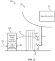
- System 200 includes an external brake cooling apparatus 220 (also referred to herein as a cooling apparatus).
- Cooling apparatus 220 is configured to receive information from the aircraft 100 through a communication channel 222.
- Communication channel 222 may be wired or wireless.
- BCU 150 may be in electronic communication with cooling apparatus 220.
- cooling apparatus 220 is an external cooling fan configured to direct cooling air towards the aircraft brake.
- cooling apparatus 220 may be a cooling fan positioned proximate each brake mechanism, such as an external or auxiliary unit that airport personnel may position proximate the landing gear at a gate following landing.
- cooling apparatus 220 may be located externally (i.e., offboard and/or not mounted to the aircraft) from the aircraft 100. It is contemplated herein, however, that cooling apparatus 220 may be any suitable external brake cooling apparatus, including a fan, a liquid cooling apparatus, etc.
- cooling apparatus 220 is controlled by the aircraft 100. More particularly, BCU 150 may include a fan control algorithm 224 configured to receive brake measurements via communication channel 226. In this regard, BCU 150 may be in electronic communication with brake 160.
- brake 160 may include one or more sensors (e.g., a temperature sensor 161) for providing temperature data to fan control algorithm 224. Said brake measurements may include brake temperature data.
- fan control algorithm 224 may be configured to control cooling apparatus 220 based upon brake temperature.
- Fan control algorithm 224 may be further configured to receive aircraft data via communication channel 228, for example from avionics unit 140 (see FIG. 1A ). Said aircraft data may include data such as time before departure, expected taxi duration, etc.
- BCU 150 may be in electronic communication with avionics unit 140 (see FIG. 1A ).
- fan control algorithm 224 may be configured to control cooling apparatus 220 based upon the expected time before departure and expected taxi duration. Fan control algorithm 224 may generate and send a cooling apparatus control signal (e.g., a fan speed signal) to cooling apparatus 220 via communication channel 222 based upon the information received via communication channel 226 and communication channel 228.
- a cooling apparatus control signal e.g., a fan speed signal
- Fan control algorithm 224 may generate and send a cooling apparatus control signal (e.g., a fan speed signal) to cooling apparatus 220 via communication channel 222 at predetermined intervals such that the cooling apparatus 220 is controlled with the use of "live" data from aircraft 100.
- the communication channel 222 may provide cooling apparatus 220 with a flow of regularly updated data, for example every second, every few seconds, every minute, or any other suitable rate for providing accurate aircraft and brake data as the cooling apparatus 220 provides cooling to the aircraft brake.
- the data exchanged between the aircraft 100 and cooling apparatus 220 can be anonymized through the use of data anonymization techniques. In various embodiments, the data exchanged between the aircraft 100 and cooling apparatus 220 can be anonymized through the use of encryption. In this way, aircraft data remains protected even if communication channel 222 or cooling apparatus 220 are compromised.
- System 201 may be similar to system 200 of FIG. 2 , except that the fan control algorithm 224 is located onboard the cooling apparatus 220 instead of onboard the aircraft 100.
- cooling apparatus 220 further includes fan control algorithm 224, which includes one or more controllers (e.g., processors) and one or more tangible, non-transitory memories capable of implementing digital or programmatic logic.
- the one or more controllers are one or more of a general purpose processor, digital signal processor (DSP), application specific integrated circuit (ASIC), field programmable gate array (FPGA), or other programmable logic device, discrete gate, transistor logic, or discrete hardware components, or any various combinations thereof or the like.
- DSP digital signal processor
- ASIC application specific integrated circuit
- FPGA field programmable gate array
- BCU 150 may send measurements for fan control (e.g., brake temperature, time before departure, expected taxi duration, etc.) to cooling apparatus 220 via communication channel 222.
- Fan control algorithm 224 may then use the measurements sent by BCU 150 to calculate a control signal (e.g., a fan speed signal) for controlling cooling apparatus 220.
- System 202 may be similar to system 201 of FIG. 3 , except that the fan control algorithm 224 receives brake data (e.g., brake temperature measurements) from brake 160 via communication channel 227 for controlling cooling apparatus 220.
- brake 160 may comprise a controller (e.g., a microcontroller) configured to collect said brake data and send said brake data directly to cooling apparatus 220-bypassing BCU 150. In this manner, brake 160 may be in electronic communication with cooling apparatus 220.
- various fan control algorithm parameters 230 may be uploaded onto cooling apparatus 220 (e.g., saved into a non-transitory memory). Said fan control algorithm parameters 230 may include a brake wear rate profile, departure time, etc.). In this manner, fan control algorithm 224 may use parameters 230 and brake data (e.g., brake temperature measurements) received from brake 160 via communication channel 227 for calculating a cooling apparatus control signal (e.g., a fan speed control signal).
- brake data e.g., brake temperature measurements
- the rate of wear of brake components does not vary linearly with temperature.
- Various brake disks may have a different relationship between wear rate and temperature. However, there is a temperature at which the wear rate peaks and, beyond that temperature, wear rate decreases with increasing temperature, at least for a given range of temperature increase.
- the brake temperature can be very high-e.g. in excess of 200°C (392°F)-it may not be advisable to cool the brakes as the brakes would have to pass through temperatures where the wear rate is substantially increased before ambient temperature is reached. This would result in significant wear during the taxiing phase.
- FIG. 5 through FIG. 6 of the present disclosure describes brake cooling methods by taking into account the relationship between brake wear rate and temperature, with the aim of minimizing wear rate while keeping temperature below a maximum threshold.
- the brake cooling methods described with reference to FIG. 5 through FIG. 6 may be implemented by fan control algorithm 224 (see FIG. 2 through FIG. 4 ).
- fan control algorithm 224 may implement any suitable brake cooling method without departing from the scope of the present disclosure.
- the system and method of this disclosure determines the brake temperature and also uses the temperature for the brake in question at which the maximum wear rate occurs, T _WEAR_MAX as well as the maximum allowed brake temperature T MAX .
- T _WEAR_MAX can be identified from the wear rate profile.
- T _MAX can be set by the pilot according to departure regulations for safety and/or brake manufacturer suggestions (e.g. based on brake temperature operating range).
- the brake temperature is compared with T _WEAR_MAX and the cooling is controlled based on the comparison.
- the cooling system may also be controlled such that the brake temperature does not exceed T MAX .
- the brake cooling can be activated to bring the temperature down to a preferred low temperature.
- the brake cooling should not be activated since reducing the temperature towards T _WEAR_MAX will result in an increase in wear rate.
- the active cooling system should be controlled such that the brake temperature is kept as low as possible.
- the wear rate of carbon brakes may be characterized by a profile that is similar for all manufacturers, with a single peak occurring around 200°C (392°F) (or around 100°C (212°F) for some brake manufacturers).
- a generalization of carbon brakes wear rate profile is shown in FIG. 5 , where the following quantities are shown:
- FIG. 6 A simple embodiment of an exemplary methodology which considers a typical wear rate profile for carbon brakes is presented in FIG. 6 .
- T_WEAR_MAX and either T MAX or, more preferred, as shown, T_ON.
- the temperature T of the brake is determined at 301, using any known temperature measuring means, and/or estimation algorithms.
- the temperature T is compared with T_WEAR_MAX
- the cooling can be activated (brake cooling ON).
- TWEAR MAX a predetermined temperature threshold at which the cooling system is switched off because the desired temperature has been reached. In an example, this can be set at ambient temperature, although other values can be set. If the temperature is above T_OFF, (No), the brake cooling system is activated or switched on at 304. If the temperature is already below T_OFF, the brake cooling is set to OFF at 305. Moving from T_WEAR_MAX to the left of the graph of FIG. 5 reduces wear rate.
- the brake cooling should not be switched on unless temperature T is, or is approaching the maximum permitted temperature T MAX. This is because, as can be seen in FIG. 5 , switching on cooling would move to the left in the graph on FIG. 5 towards the peak T_WEAR_MAX, thus increasing wear rate.
- the cooling is set to OFF (305). If, however, T is not less than T WEAR MAX but is also not less than T_ON - i.e. is approaching T_MAX, (306, NO), then the cooling should be set to ON to avoid reaching T MAX
- the temperature T continues to be measured, or is measured at periodic intervals, for continuous or regular control of the brake cooling.
- the wear rate profile of the brake may be learned by processing measurements and information collected by the avionics systems and/or by the brake assembly sensors.
- the information processed can include brake temperature evolution, readings of the electronic wear pin, applied brake pressure, whether the aircraft was taxiing or landing, etc.
- the present disclosure allows the control of the cooling system and, hence, the brake temperature to not only prevent overheating, but also to minimize break wear using a simple algorithm.
- the algorithm may require only three parameters.
- the cooling system is only activated where needed, thus resulting in energy savings.
- the brake wear rate profile is unknown, it can be derived by means of learning algorithms processing information collected by brake assembly sensors and by aircraft avionics systems.
- any of the method or process descriptions may be executed in any order and are not necessarily limited to the order presented.
- any reference to singular includes plural embodiments, and any reference to more than one component or step may include a singular embodiment or step.
- Elements and steps in the figures are illustrated for simplicity and clarity and have not necessarily been rendered according to any particular sequence. For example, steps that may be performed concurrently or in different order are only illustrated in the figures to help to improve understanding of embodiments of the present, representative disclosure.
- Any reference to attached, fixed, connected, or the like may include permanent, removable, temporary, partial, full and/or any other possible attachment option. Additionally, any reference to without contact (or similar phrases) may also include reduced contact or minimal contact. Surface shading lines may be used throughout the figures to denote different parts or areas, but not necessarily to denote the same or different materials. In some cases, reference coordinates may be specific to each figure.
- references to "one embodiment,” “an embodiment,” “various embodiments,” etc. indicate that the embodiment described may include a particular feature, structure, or characteristic, but every embodiment may not necessarily include the particular feature, structure, or characteristic. Moreover, such phrases are not necessarily referring to the same embodiment. Further, when a particular feature, structure, or characteristic is described in connection with an embodiment, it is submitted that it is within the knowledge of one skilled in the art to affect such feature, structure, or characteristic in connection with other embodiments, whether or not explicitly described. After reading the description, it will be apparent to one skilled in the relevant art(s) how to implement the disclosure in alternative embodiments.
Landscapes
- Engineering & Computer Science (AREA)
- General Engineering & Computer Science (AREA)
- Mechanical Engineering (AREA)
- Aviation & Aerospace Engineering (AREA)
- Transportation (AREA)
- Manufacturing & Machinery (AREA)
- Braking Arrangements (AREA)
Applications Claiming Priority (1)
| Application Number | Priority Date | Filing Date | Title |
|---|---|---|---|
| US17/503,084 US20230121112A1 (en) | 2021-10-15 | 2021-10-15 | Systems and methods for controlling external brake cooling apparatus according to aircraft and brake status |
Publications (1)
| Publication Number | Publication Date |
|---|---|
| EP4166404A1 true EP4166404A1 (de) | 2023-04-19 |
Family
ID=83361163
Family Applications (1)
| Application Number | Title | Priority Date | Filing Date |
|---|---|---|---|
| EP22196204.6A Pending EP4166404A1 (de) | 2021-10-15 | 2022-09-16 | Systeme und verfahren zur steuerung einer externen bremskühlvorrichtung gemäss flugzeug und bremszustand |
Country Status (2)
| Country | Link |
|---|---|
| US (1) | US20230121112A1 (de) |
| EP (1) | EP4166404A1 (de) |
Families Citing this family (1)
| Publication number | Priority date | Publication date | Assignee | Title |
|---|---|---|---|---|
| GB2601791A (en) * | 2020-12-10 | 2022-06-15 | Airbus Operations Ltd | Aircraft brake temperature control system |
Citations (6)
| Publication number | Priority date | Publication date | Assignee | Title |
|---|---|---|---|---|
| US20190301554A1 (en) * | 2018-03-29 | 2019-10-03 | Honeywell International Inc. | Active brake cooling using nitrogen enriched air |
| EP3101277B1 (de) * | 2015-06-04 | 2020-05-13 | Airbus Operations Limited | Flugzeug mit kühlgebläse für bremse |
| CN211441869U (zh) * | 2019-11-24 | 2020-09-08 | 西安航空制动科技有限公司 | 一种多轮系飞机主机轮刹车冷却电机控制系统 |
| US20210239173A1 (en) * | 2020-01-30 | 2021-08-05 | The Boeing Company | Active Cooling System for Landing Gear Brakes |
| EP3936396A1 (de) * | 2020-07-10 | 2022-01-12 | Goodrich Corporation | Bremskühlungsregelung |
| EP4011723A2 (de) * | 2020-12-10 | 2022-06-15 | Airbus Operations Limited | Flugzeugbremstemperaturregelsystem |
-
2021
- 2021-10-15 US US17/503,084 patent/US20230121112A1/en active Pending
-
2022
- 2022-09-16 EP EP22196204.6A patent/EP4166404A1/de active Pending
Patent Citations (6)
| Publication number | Priority date | Publication date | Assignee | Title |
|---|---|---|---|---|
| EP3101277B1 (de) * | 2015-06-04 | 2020-05-13 | Airbus Operations Limited | Flugzeug mit kühlgebläse für bremse |
| US20190301554A1 (en) * | 2018-03-29 | 2019-10-03 | Honeywell International Inc. | Active brake cooling using nitrogen enriched air |
| CN211441869U (zh) * | 2019-11-24 | 2020-09-08 | 西安航空制动科技有限公司 | 一种多轮系飞机主机轮刹车冷却电机控制系统 |
| US20210239173A1 (en) * | 2020-01-30 | 2021-08-05 | The Boeing Company | Active Cooling System for Landing Gear Brakes |
| EP3936396A1 (de) * | 2020-07-10 | 2022-01-12 | Goodrich Corporation | Bremskühlungsregelung |
| EP4011723A2 (de) * | 2020-12-10 | 2022-06-15 | Airbus Operations Limited | Flugzeugbremstemperaturregelsystem |
Also Published As
| Publication number | Publication date |
|---|---|
| US20230121112A1 (en) | 2023-04-20 |
Similar Documents
| Publication | Publication Date | Title |
|---|---|---|
| US11136145B2 (en) | Brake temperature prediction and cooling time functionality | |
| EP3048018B1 (de) | Bremskühlungsschätzverfahren und -systeme | |
| EP2964535B1 (de) | Flugzeugbremsen-frühwarnsystem | |
| EP4166404A1 (de) | Systeme und verfahren zur steuerung einer externen bremskühlvorrichtung gemäss flugzeug und bremszustand | |
| EP3088266B1 (de) | Bremsenauswahlsystem und -verfahren | |
| EP3403892B1 (de) | Beurteilung der oberflächenbedingungen von start- und landebahnen | |
| US9096204B2 (en) | System and method for determining an adaptive turnaround threshold | |
| US11407397B2 (en) | Brake temperature and turnaround time estimation systems and methods | |
| EP2876012A1 (de) | Verfahren zur Überwachung der Komponenten eines Flugzeuglandesystems | |
| US20210001823A1 (en) | Selective braking of carbon brakes to improve life | |
| EP2942246B1 (de) | Verfahren und Systeme zur Bremskühlungsschätzung | |
| US10759234B2 (en) | Aircraft tire management method and aircraft tire management device | |
| US20210362543A1 (en) | Smart Wheel Traction System (SWTS) | |
| US11970151B2 (en) | Systems and methods for aircraft antiskid braking | |
| EP3878703B1 (de) | Systeme und verfahren zur überwachung des zustands von bremsen | |
| EP3936396A1 (de) | Bremskühlungsregelung | |
| EP3450274B1 (de) | Zustandsüberwachung für eine auswechselbare einheit (lru) | |
| EP4015324A1 (de) | Bremsentemperaturschätzung | |
| US20230287950A1 (en) | Thermal harvesting for vehicle brakes | |
| EP4245622A1 (de) | Thermische energiegewinnung für fahrzeugbremsen | |
| KR102051098B1 (ko) | Fads의 방빙을 위한 능동히터 장치 | |
| CN116394683A (zh) | 一种轮胎胎压、胎温智能管理系统 | |
| CN116733877A (zh) | 用于运载工具制动器的热收集 |
Legal Events
| Date | Code | Title | Description |
|---|---|---|---|
| PUAI | Public reference made under article 153(3) epc to a published international application that has entered the european phase |
Free format text: ORIGINAL CODE: 0009012 |
|
| STAA | Information on the status of an ep patent application or granted ep patent |
Free format text: STATUS: THE APPLICATION HAS BEEN PUBLISHED |
|
| AK | Designated contracting states |
Kind code of ref document: A1 Designated state(s): AL AT BE BG CH CY CZ DE DK EE ES FI FR GB GR HR HU IE IS IT LI LT LU LV MC MK MT NL NO PL PT RO RS SE SI SK SM TR |
|
| STAA | Information on the status of an ep patent application or granted ep patent |
Free format text: STATUS: REQUEST FOR EXAMINATION WAS MADE |
|
| 17P | Request for examination filed |
Effective date: 20231019 |
|
| RBV | Designated contracting states (corrected) |
Designated state(s): AL AT BE BG CH CY CZ DE DK EE ES FI FR GB GR HR HU IE IS IT LI LT LU LV MC MK MT NL NO PL PT RO RS SE SI SK SM TR |