EP4166393A1 - Vehicle exterior display device - Google Patents
Vehicle exterior display device Download PDFInfo
- Publication number
- EP4166393A1 EP4166393A1 EP22200851.8A EP22200851A EP4166393A1 EP 4166393 A1 EP4166393 A1 EP 4166393A1 EP 22200851 A EP22200851 A EP 22200851A EP 4166393 A1 EP4166393 A1 EP 4166393A1
- Authority
- EP
- European Patent Office
- Prior art keywords
- display
- vehicle
- pedestrian
- crosswalk
- information
- Prior art date
- Legal status (The legal status is an assumption and is not a legal conclusion. Google has not performed a legal analysis and makes no representation as to the accuracy of the status listed.)
- Granted
Links
Images


Classifications
-
- B—PERFORMING OPERATIONS; TRANSPORTING
- B60—VEHICLES IN GENERAL
- B60Q—ARRANGEMENT OF SIGNALLING OR LIGHTING DEVICES, THE MOUNTING OR SUPPORTING THEREOF OR CIRCUITS THEREFOR, FOR VEHICLES IN GENERAL
- B60Q1/00—Arrangement of optical signalling or lighting devices, the mounting or supporting thereof or circuits therefor
- B60Q1/26—Arrangement of optical signalling or lighting devices, the mounting or supporting thereof or circuits therefor the devices being primarily intended to indicate the vehicle, or parts thereof, or to give signals, to other traffic
- B60Q1/50—Arrangement of optical signalling or lighting devices, the mounting or supporting thereof or circuits therefor the devices being primarily intended to indicate the vehicle, or parts thereof, or to give signals, to other traffic for indicating other intentions or conditions, e.g. request for waiting or overtaking
- B60Q1/503—Arrangement of optical signalling or lighting devices, the mounting or supporting thereof or circuits therefor the devices being primarily intended to indicate the vehicle, or parts thereof, or to give signals, to other traffic for indicating other intentions or conditions, e.g. request for waiting or overtaking using luminous text or symbol displays in or on the vehicle, e.g. static text
- B60Q1/5035—Arrangement of optical signalling or lighting devices, the mounting or supporting thereof or circuits therefor the devices being primarily intended to indicate the vehicle, or parts thereof, or to give signals, to other traffic for indicating other intentions or conditions, e.g. request for waiting or overtaking using luminous text or symbol displays in or on the vehicle, e.g. static text electronic displays
- B60Q1/5037—Arrangement of optical signalling or lighting devices, the mounting or supporting thereof or circuits therefor the devices being primarily intended to indicate the vehicle, or parts thereof, or to give signals, to other traffic for indicating other intentions or conditions, e.g. request for waiting or overtaking using luminous text or symbol displays in or on the vehicle, e.g. static text electronic displays the display content changing automatically, e.g. depending on traffic situation
-
- B—PERFORMING OPERATIONS; TRANSPORTING
- B60—VEHICLES IN GENERAL
- B60Q—ARRANGEMENT OF SIGNALLING OR LIGHTING DEVICES, THE MOUNTING OR SUPPORTING THEREOF OR CIRCUITS THEREFOR, FOR VEHICLES IN GENERAL
- B60Q1/00—Arrangement of optical signalling or lighting devices, the mounting or supporting thereof or circuits therefor
- B60Q1/26—Arrangement of optical signalling or lighting devices, the mounting or supporting thereof or circuits therefor the devices being primarily intended to indicate the vehicle, or parts thereof, or to give signals, to other traffic
- B60Q1/50—Arrangement of optical signalling or lighting devices, the mounting or supporting thereof or circuits therefor the devices being primarily intended to indicate the vehicle, or parts thereof, or to give signals, to other traffic for indicating other intentions or conditions, e.g. request for waiting or overtaking
- B60Q1/543—Arrangement of optical signalling or lighting devices, the mounting or supporting thereof or circuits therefor the devices being primarily intended to indicate the vehicle, or parts thereof, or to give signals, to other traffic for indicating other intentions or conditions, e.g. request for waiting or overtaking for indicating other states or conditions of the vehicle
-
- B—PERFORMING OPERATIONS; TRANSPORTING
- B60—VEHICLES IN GENERAL
- B60Q—ARRANGEMENT OF SIGNALLING OR LIGHTING DEVICES, THE MOUNTING OR SUPPORTING THEREOF OR CIRCUITS THEREFOR, FOR VEHICLES IN GENERAL
- B60Q1/00—Arrangement of optical signalling or lighting devices, the mounting or supporting thereof or circuits therefor
- B60Q1/26—Arrangement of optical signalling or lighting devices, the mounting or supporting thereof or circuits therefor the devices being primarily intended to indicate the vehicle, or parts thereof, or to give signals, to other traffic
- B60Q1/50—Arrangement of optical signalling or lighting devices, the mounting or supporting thereof or circuits therefor the devices being primarily intended to indicate the vehicle, or parts thereof, or to give signals, to other traffic for indicating other intentions or conditions, e.g. request for waiting or overtaking
- B60Q1/547—Arrangement of optical signalling or lighting devices, the mounting or supporting thereof or circuits therefor the devices being primarily intended to indicate the vehicle, or parts thereof, or to give signals, to other traffic for indicating other intentions or conditions, e.g. request for waiting or overtaking for issuing requests to other traffic participants; for confirming to other traffic participants they can proceed, e.g. they can overtake
-
- G—PHYSICS
- G06—COMPUTING OR CALCULATING; COUNTING
- G06F—ELECTRIC DIGITAL DATA PROCESSING
- G06F3/00—Input arrangements for transferring data to be processed into a form capable of being handled by the computer; Output arrangements for transferring data from processing unit to output unit, e.g. interface arrangements
- G06F3/14—Digital output to display device ; Cooperation and interconnection of the display device with other functional units
-
- G—PHYSICS
- G08—SIGNALLING
- G08G—TRAFFIC CONTROL SYSTEMS
- G08G1/00—Traffic control systems for road vehicles
- G08G1/005—Traffic control systems for road vehicles including pedestrian guidance indicator
-
- G—PHYSICS
- G08—SIGNALLING
- G08G—TRAFFIC CONTROL SYSTEMS
- G08G1/00—Traffic control systems for road vehicles
- G08G1/16—Anti-collision systems
- G08G1/166—Anti-collision systems for active traffic, e.g. moving vehicles, pedestrians, bikes
-
- B—PERFORMING OPERATIONS; TRANSPORTING
- B60—VEHICLES IN GENERAL
- B60Q—ARRANGEMENT OF SIGNALLING OR LIGHTING DEVICES, THE MOUNTING OR SUPPORTING THEREOF OR CIRCUITS THEREFOR, FOR VEHICLES IN GENERAL
- B60Q1/00—Arrangement of optical signalling or lighting devices, the mounting or supporting thereof or circuits therefor
- B60Q1/26—Arrangement of optical signalling or lighting devices, the mounting or supporting thereof or circuits therefor the devices being primarily intended to indicate the vehicle, or parts thereof, or to give signals, to other traffic
- B60Q1/50—Arrangement of optical signalling or lighting devices, the mounting or supporting thereof or circuits therefor the devices being primarily intended to indicate the vehicle, or parts thereof, or to give signals, to other traffic for indicating other intentions or conditions, e.g. request for waiting or overtaking
- B60Q1/507—Arrangement of optical signalling or lighting devices, the mounting or supporting thereof or circuits therefor the devices being primarily intended to indicate the vehicle, or parts thereof, or to give signals, to other traffic for indicating other intentions or conditions, e.g. request for waiting or overtaking specific to autonomous vehicles
Definitions
- the present invention relates to a vehicle exterior display device.
- a pedestrian who needs to cross a roadway using a crosswalk can predict whether a vehicle stops in front of the crosswalk by making eye contact or the like with a driver when the driver is on the vehicle located in front of the crosswalk.
- a vehicle traveling by automated driving without a driver drives through a crosswalk.
- a pedestrian who needs to cross a roadway using a crosswalk is located in front of the crosswalk and a vehicle approaching toward the crosswalk is driving in automated driving, it is difficult for the pedestrian to predict whether the vehicle will stop in front of the crosswalk.
- International Publication WO 2017/073634 A discloses a technique in which an automated driving vehicle irradiates a road surface with a display of information indicating preliminary notification of stop to a pedestrian.
- the present invention has been made in view of the above, and aims to provide a vehicle exterior display device capable of performing display focused on a target of the message according to a positional relationship between a pedestrian and an own vehicle, and achieving transmission of useful information to the target.
- a vehicle exterior display device includes an own vehicle position information acquisition unit that acquires position information regarding an own vehicle; a crosswalk position information acquisition unit that acquires position information regarding a crosswalk; a surrounding information detection unit that detects a pedestrian around the own vehicle; a display unit that includes a plurality of display regions visually recognizable from outside of the own vehicle and is capable of displaying different types of display information visually recognizable by the display region; and a display controller that changes display information displayed by the display unit and the display region in which the display information is displayed, based on a positional relationship among the own vehicle, the crosswalk, and the pedestrian, wherein each of the plurality of display regions includes at least a far display region and a near display region, the display controller controls, out of the far display region and the near display region, the display region visible to the pedestrian existing around the crosswalk, to display display information related to behavior of a vehicle, and at least when a positional relationship between the vehicle and the pedestrian existing around the crosswalk is a
- FIG. 1 is a diagram illustrating a vehicle exterior display device according to the present invention.
- FIG. 2 is a diagram illustrating an example of a display region setting method used by a vehicle exterior display device according to the first embodiment.
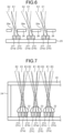
- FIG. 3 is a diagram illustrating a configuration of a display unit according to the first embodiment.
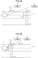
- FIG. 4A is a diagram illustrating a display region and display information when a relative position between an own vehicle and a pedestrian is a far position according to the first embodiment.
- FIG. 4B is a diagram illustrating a display region and display information when the relative position between the own vehicle and the pedestrian is a near position according to the first embodiment.
- the vehicle exterior display device 1 is a display device that is applied to a vehicle V and performs various types of displays.
- the vehicle V to which the vehicle exterior display device 1 is applied may be any vehicle using a motor or an engine as a drive source, such as an electric vehicle (EV), a hybrid electric vehicle (HEV), a plug-in hybrid electric vehicle (PHEV), a gasoline vehicle, or a diesel vehicle.
- the driving of the vehicle V may be any of manual driving, semi-automated driving, fully automated driving, and the like, performed by the driver.
- the vehicle V may be any of a private car owned by an individual, a rental car, a sharing car, a bus, a taxi, and a ride sharing car.
- the vehicle V will be described as a vehicle capable of automated driving (including semi-automated driving and fully automated driving).
- the vehicle exterior display device 1 assumes implementation of driving referred to as automated driving by the vehicle V, and based on this assumption, implements appropriate display related to the behavior of the vehicle according to the positional relationship with persons outside the vehicle V.
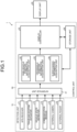
- the vehicle exterior display device 1 is implemented by mounting the components illustrated in FIG. 1 on the vehicle V.
- each configuration of the vehicle exterior display device 1 will be described in detail with reference to FIG. 1 .
- the vehicle V may be referred to as an "own vehicle V".
- connection method between individual components for supplying power, transmitting and receiving control signals, various types of information, and the like may be any of wired connection (including optical communication via an optical fiber, for example) via a wiring material such as an electric wire or an optical fiber, and wireless connection such as radio communication or contactless power feeding, unless otherwise specified.
- the vehicle exterior display device 1 includes a detection unit 10, a display unit 20, and a control unit 30.
- the detection unit 10 is implemented by equipping the vehicle V with the components illustrated in FIG. 1 .
- the detection unit 10 includes a GPS receiver 11, a traveling system actuator 12, a vehicle state detector 13, a communication module 14, an external camera 15, and an external radar 16.
- the GPS receiver 11 detects current position information indicating the current position of the vehicle V, that is, own vehicle position information X1, as surrounding status information.
- the GPS receiver 11 receives a radio wave transmitted from a GPS satellite to acquire GPS information (latitude and longitude coordinates) of the vehicle V as the own vehicle position information X1.
- the traveling system actuator 12 includes various devices needed for the vehicle V to travel.
- the traveling system actuator 12 typically includes a traveling powertrain, a steering device, a braking device, and the like.
- the traveling powertrain is a driving device that drives the vehicle V.
- the steering device is a device that steers the vehicle V.
- the braking device is a device that brakes the vehicle V.
- the vehicle state detector 13 detects vehicle state information including vehicle speed information, acceleration information, steering angle information, accelerator pedal operation amount information, brake pedal operation amount information, shift position information, current value/voltage value information, and charge amount information.
- the vehicle state detector 13 includes, for example, various detectors and sensors such as a vehicle speed sensor, an acceleration sensor, a steering angle sensor, an accelerator sensor, a brake sensor, a shift position sensor, and an ammeter/voltmeter.
- the vehicle state detector 13 may include an entire processing unit such as an electronic control unit (ECU) that controls individual components in the vehicle V.
- the communication module 14 transmits and receives information by radio communication to and from an external device of the vehicle V, such as another vehicle, an on-road device, a cloud device, or an electronic device possessed by a person outside the vehicle V.
- the communication module 14 detects surrounding status information including, for example, surrounding image information, external object information, traffic information, and the own vehicle position information X1.
- the communication module 14 communicates with an external device by various types of radio communication such as wide-range radio communication and narrow-range radio communication.
- examples of the wide-range radio communication system include radio broadcasting (AM, FM), TV (UHF, 4K, 8K), telephone, GPS, and WiMAX (registered trademark).
- examples of the narrow-range radio communication system include ETC/DSRC, VICS (registered trademark), wireless LAN, and millimeter wave communication.
- the external camera 15 captures an image of the surroundings of the vehicle V constituting the surrounding image information and an image of a traveling road surface of the vehicle V constituting the white line information, as the surrounding status information.
- the external radar 16 detects, as the surrounding status information, external object information using infrared rays, millimeter waves, ultrasonic waves, or the like.
- the display unit 20, provided on the vehicle V has a plurality of display regions E, specifically two display regions E1 and E2 in the present embodiment, which can be visually recognized from the outside of the own vehicle V, and it is possible to display different display information M each of which is visually recognizable by the display regions E1 and E2.
- the display unit 20 is installed outside or inside the cabin in front of the vehicle V, and includes: a far display region E1 that is a region in which display is performed toward a far front of the vehicle V, particularly a far front left side in the case of left-hand traffic; and a near display region E2 that is a region adjacent to the far display region E1 and a region in which display is performed toward a near front of the vehicle V, particularly a near front left side in the case of left-hand traffic.
- each of the display regions E1 and E2 is in a range in which the display of the display unit 20 is visible only by a specific pedestrian, having a display angle that can be displayed from the display unit 20.
- Each of the display regions E1 and E2 of the present embodiment changes display information M to be displayed according to the relative position between the own vehicle V and a pedestrian 100 around a crosswalk 200.
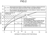
- a method of calculating the far display region E1 when assuming a vehicle traveling on a local road at a speed of 60 km/h will be described.
- a solid line S1 represents a deceleration profile when the vehicle V stops at a deceleration that does not make the occupant feel uncomfortable
- a dotted line S2 represents a relationship between a distance and a speed at which the vehicle V stops by sudden braking.
- the distance needed for the vehicle V to stop by sudden braking at the speed at a stop start time point is about 11 meters.
- the traveling direction of the vehicle V is a forward direction
- a pedestrian present within 4 meters from the center cross section of the vehicle V in the left-right direction and present within 11 meters in front of the vehicle V rushes out, it would not be possible to avoid a collision. Therefore, it is desirable that the region is not visible to the pedestrian present in this range.
- the far display region E1 is set based on Formula (1).
- the method of determining ⁇ is an example, and there is no restriction regarding the friction coefficient between the tire and the road surface, the assumed vehicle speed, deceleration, a deceleration start position, or the like.
- the determination may be made in consideration of parameters that affect a range in which the vehicle can be safely stopped, such as a road surface condition, weather, and accuracy of various sensors.
- the determination may be made in consideration of the influence of discomfort or the like on the occupant of the automated driving vehicle when the vehicle decelerates.
- the display unit 20 includes a light emitting unit 21, lenses 22, a cover 23, a case 24, and a substrate 25.
- the light emitting unit 21 in the present embodiment is be to be mounted on the substrate 25 and arranged in plurality on a plane.
- the light emitting unit 21 in the present embodiment includes a plurality of light emitting unit groups 21a and 21b each corresponding to each of the lenses 22.
- the plurality of light emitting unit groups 21a and 21b specifically includes a first light emitting unit group 21a corresponding to the far display region E1 and a second light emitting unit group 21b corresponding to the near display region E2.
- the first light emitting unit group 21a includes a plurality of first light emitting units 211
- the second light emitting unit group 21b includes a plurality of second light emitting units 212.
- the first light emitting unit 211 is disposed corresponding to each lens 22, and is disposed at the center with respect to each lens 22 in the present embodiment.
- the second light emitting unit 212 is disposed corresponding to each lens 22, and is disposed in a state of being adjacent to the first light emitting unit 211, at one of both ends with respect to each lens 22 in the present embodiment.
- the first light emitting unit group 21a and the second light emitting unit group 21b are disposed alternately and emit light corresponding to the display information M related to the behavior of the own vehicle V.
- the display information M related to the behavior of own vehicle V is displayed as the display information M that changes according to display region E. Therefore, the first light emitting unit group 21a and the second light emitting unit group 21b emit light based on mutually different pieces of display information M. Specifically, when the relative position between the own vehicle V and the pedestrian 100 around the crosswalk 200 is a far position, the first light emitting unit group 21a corresponding to the far display region E1 emits light for displaying the display information M1 related to future vehicle behavior corresponding to the far position, while the second light emitting unit group 21b corresponding to the near display region E2 emits light for displaying display information M2 related to current vehicle behavior corresponding to the far position.
- the first light emitting unit group 21a corresponding to the far display region E1 emits light for displaying display information M4 related to future vehicle behavior corresponding to the near position
- the second light emitting unit group 21b corresponding to the near display region E2 emits light for displaying display information M3 related to current vehicle behavior corresponding to the near position.
- the first light emitting unit group 21a and the second light emitting unit group 21b emit light based on mutually different pieces of display information M according to the positional relationship between the vehicle V and the pedestrian 100 around the crosswalk 200.
- the lens 22 has a semicircular cross section and transmits light from the light emitting unit 21.
- the lens 22 has different positions where light from the light emitting unit 21 is visually recognizable due to refraction of light according to an angle viewed from the outside of the vehicle V.
- the cover 23 has transparency and allows light from the light emitting unit 21 to be visually recognized from the outside of the vehicle V.
- the case 24 surrounds the light emitting unit 21 and the lens 22, and the cover 23 is fitted to the outside of the vehicle V of the case 24.
- control unit 30 integrally controls individual components of the vehicle exterior display device 1.
- the control unit 30 may also be incorporated as an electronic control unit that integrally controls the entire vehicle V.
- the control unit 30 executes various types of arithmetic processing for implementation of traveling of the vehicle V.
- the control unit 30 includes an electronic circuit mainly including a known microcomputer, including a central processing device such as a central processing unit (CPU), a micro processing unit (MPU), an application specific integrated circuit (ASIC), and a field programmable gate array (FPGA), and including read only memory (ROM), random access memory (RAM), and an interface.
- the control unit 30 is electrically connected to the detection unit 10 and the display unit 20.
- the control unit 30 may be electrically connected with the detection unit 10 and the display unit 20 via an ECU (for example, a body ECU) that controls individual components of the vehicle V.
- the control unit 30 can exchange, with individual components, various electric signals such as various detection signals and a drive signal for driving the individual components.
- control unit 30 functionally and conceptually includes an interface unit 31, an own vehicle position information acquisition unit 32, a crosswalk position information acquisition unit 33, a surrounding information acquisition unit 34, a display controller 35, and a storage unit 36.
- the interface unit 31, the own vehicle position information acquisition unit 32, the crosswalk position information acquisition unit 33, the surrounding information acquisition unit 34, the display controller 35, and the storage unit 36 can exchange various types of information with various types of electrically connected devices.
- the interface unit 31 is an interface for transmitting and receiving various types of information to and from individual components such as a detection unit. Furthermore, the interface unit 31 is electrically connectable to the detection unit 10, the own vehicle position information acquisition unit 32, the crosswalk position information acquisition unit 33, and the surrounding information acquisition unit 34.
- the interface unit 31 has functions such as a function of performing wired communication of transferring information with individual components via an electric wire or the like and a function of performing wireless communication of information with individual components via a radio communication unit and the like.
- the own vehicle position information acquisition unit 32 acquires the own vehicle position information X1.
- the own vehicle position information acquisition unit 32 acquires the own vehicle position information X1 based on information received by the GPS receiver 11, for example.
- the crosswalk position information acquisition unit 33 acquires position information regarding the crosswalk 200.
- the crosswalk position information acquisition unit 33 acquires crosswalk position information X2 that is position information regarding the crosswalk 200 existing in the traveling direction of the own vehicle V based on the own vehicle position information X1 and map information stored in advance in the storage unit 36.
- the crosswalk position information acquisition unit 33 may acquire the crosswalk position information X2 based on a surrounding image of the own vehicle V captured by the external camera 15.
- the crosswalk position information acquisition unit 33 may acquire the crosswalk position information X2 based on the own vehicle position information X1 and map information stored outside the own vehicle V acquired by the communication module 14.
- the surrounding information acquisition unit 34 acquires information around the own vehicle V.
- the surrounding information acquisition unit 34 in the present embodiment acquires information related to the pedestrian 100 being a viewer of the display unit 20 and existing around the own vehicle V.
- the surrounding information acquisition unit 34 may acquire pedestrian position information X3 existing around the own vehicle V based on the surrounding image of the own vehicle V captured by the external camera 15.
- the pedestrian position information X3 may be acquired based on surrounding objects of the own vehicle V scanned and detected by the external radar 16.
- the display controller 35 controls the display information M regarding the behavior of the own vehicle V displayed on the display unit 20 in the far display region E1 and the near display region E2 of the display unit 20.
- the display controller 35 of the present embodiment changes the display information M related to the behavior of the own vehicle V in the display region E of the display unit 20 according to the relative position between the own vehicle V and the surrounding pedestrian 100 based on the positional relationship among the own vehicle position information X1 acquired by the own vehicle position information acquisition unit 32, the crosswalk position information X2 acquired by the crosswalk position information acquisition unit 33, and the pedestrian position information X3 acquired by the surrounding information acquisition unit 34.
- the positional relationship between the crosswalk 200 and the pedestrian 100 is calculated based on the crosswalk position information X2 acquired by the crosswalk position information acquisition unit 33 and based on the pedestrian position information X3 acquired by the surrounding information acquisition unit 34, and determination is made whether the pedestrian 100 is located around the crosswalk 200, that is, whether the pedestrian 100 exists around the crosswalk 200.
- the determination that pedestrian 100 exits around the crosswalk 200 it is allowable to determine that the pedestrian 100 is about to cross the crosswalk 200 by determining that pedestrian 100 is located around the crosswalk 200, further determining whether the face or body direction of pedestrian 100 is directed toward the crosswalk 200, and determining that pedestrian 100 is directed toward the crosswalk 200.
- the positional relationship between the pedestrian 100 and the own vehicle V around the crosswalk 200 is calculated based on the own vehicle position information X1 acquired by the own vehicle position information acquisition unit 32 and the pedestrian position information X3 acquired by the surrounding information acquisition unit 34.
- the display information M1 regarding future behavior of the own vehicle according to the far position is displayed in the far display region E1 of the display unit 20 while the display information M2 regarding current behavior of the own vehicle according to the far position is displayed in the near display region E2.
- the positional relationship between the pedestrian 100 around the crosswalk 200 and the own vehicle V is calculated.
- the display information M3 related to the current behavior of the own vehicle according to the near position is displayed on the display unit 20 in the near display region E2 of the display unit 20, and the display information M4 related to the future behavior of the own vehicle according to the near position is displayed in the far display region E1.
- the display controller 35 performs display of the display information M1 such as "CAR STOPPING" related to the future behavior of the vehicle toward the pedestrian 100 present around the crosswalk 200, as the display information M displayed in the far display region E1 of the display unit 20. This enables the pedestrian 100 who is located around the crosswalk 200 and is about to cross the crosswalk 200 to visually recognize the display of the display unit 20.
- the near display region E2 performs a display of display information M2 regarding the current behavior of the vehicle, such as "CAR PASSING" directed for the pedestrian 400 present at a position closer to the vehicle V than the pedestrian 100 present around the crosswalk 200, which is different from the display information M for the pedestrian 100 present around the crosswalk 200.
- the first light emitting unit group 21a emits light based on the display information M1 indicating "CAR STOPPING", while a second light emitting unit group 21b emits light based on the display information M2 indicating "CAR PASSING".
- the display information M displayed in the near display region E2 of the display unit 20 is made by displaying the message "CAR STOPPED", which is display information M3 related to the current behavior of the vehicle toward the pedestrian 100 around the crosswalk 200.
- the display information M4 regarding the future behavior of the vehicle such as "CAR MOVING” is displayed in the far display region E1 visually recognizable by the pedestrian 500 present farther away from the vehicle V.
- the first light emitting unit group 21a emits light based on the display information M4 indicating "CAR MOVING”
- the second light emitting unit group 21b emits light based on the display information M3 indicating "CAR STOPPED”.
- the storage unit 36 is a device that stores data related to the behavior of the own vehicle.
- the storage unit 36 may be, for example, a relatively large-capacity storage device such as a hard disk, a solid state drive (SSD), or an optical disk, or may be data rewritable semiconductor memory such as RAM, flash memory, or nonvolatile static random access memory (NVSRAM).
- the storage unit 36 stores conditions and information necessary for various processes in the control unit 30, various programs and applications executed by the control unit, control data, and the like.
- the storage unit 36 stores, for example, the display information M related to the behavior of the own vehicle V displayed on the display unit 20 controlled by the display controller 35.
- Storage unit 36 can also temporarily store various types of information acquired by the own vehicle position information acquisition unit 32, the crosswalk position information acquisition unit 33, and the surrounding information acquisition unit 34, for example.
- the information in the storage unit 36 is read by the display controller 35 as necessary.
- FIG. 5 is a flowchart illustrating an example of control of the vehicle exterior display device according to the first embodiment.
- the display controller 35 determines whether the pedestrian 100 is present around the crosswalk 200 based on the pedestrian position information X3 and the crosswalk position information X2 (step S1). Specifically, a positional relationship between the crosswalk 200 and the pedestrian 100 is calculated based on the crosswalk position information X2 acquired by the crosswalk position information acquisition unit 33 and the pedestrian position information X3 acquired by the surrounding information acquisition unit 34, and a determination is made as to whether there is the pedestrian 100 who is about to cross the crosswalk 200. The display controller 35 determines that pedestrian 100 is about to cross the crosswalk 200 when the face or body of the pedestrian 100 is directed toward the crosswalk 200 or when the movement locus of the pedestrian 100 is directed toward the crosswalk 200.
- step S1: No When having determined that pedestrian 100 is not present around the crosswalk 200 (step S1: No), the display controller 35 repeats step S1 until the pedestrian 100 is present around the crosswalk 200.
- the display controller 35 calculates the positional relationship among the own vehicle V, the crosswalk 200, and the pedestrian 100 based on the own vehicle position information X1, the crosswalk position information X2, and the pedestrian position information X3 (step S2).
- the display controller 35 determines whether the own vehicle V is approaching the crosswalk 200 based on the own vehicle position information X1 and the crosswalk position information X2 (step S3).
- the display controller 35 determines whether the relative position between the own vehicle V and the pedestrian 100 is a far position based on the own vehicle position information X1 and the pedestrian position information X3 (step S4).
- the display controller 35 displays the display information M1 related to the future behavior of the own vehicle at the far position in the far display region E1 and the display information M2 related to the current behavior of the own vehicle at the far position in the near display region E2 (step S5).
- the display controller 35 causes the first light emitting unit group 21a corresponding to the near display region E2 to perform light emission for displaying the display information M1 related to the future behavior of the vehicle at the far position so as to achieve display of the display information M1 related to the future behavior of the own vehicle such as "CAR STOPPING".
- the pedestrian 400 when the pedestrian 400 is present at a position closer to the own vehicle V than the pedestrian 100 present around the crosswalk 200, the pedestrian 400 present at a position closer to the own vehicle V than the pedestrian 100 present around the crosswalk 200 might erroneously perceive that the display is made for the pedestrian 400 oneself, even though the display is made for the pedestrian 100 present around the crosswalk 200.
- the second light emitting unit group 21b corresponding to the near display region E2 is controlled to emit light for displaying the display information M2 related to the current behavior of the vehicle according to the far position, and display is performed in the near display region, toward the pedestrian 400 other than the pedestrian 100 present around the crosswalk 200, such as "CAR PASSING", as a different display from the information to be displayed for the pedestrian 100 present around the crosswalk 200 (refer to FIG. 4A ).
- the display controller 35 calculates the positional relationship among the own vehicle V, the pedestrian 100, and the crosswalk 200 (step S2), determines that the own vehicle V is approaching the crosswalk 200 (step S3: Yes), and determines again whether the relative position between the own vehicle V and the pedestrian 100 is a far position (step S4).
- the display controller 35 maintains the display state of the display information M1 related to the future behavior of the own vehicle V at the far position in the far display region E1, and maintains the display state of the display information M2 related to the current behavior of the own vehicle V at the far position in the near display region E2.
- the display controller 35 When having determined that the relative position between own vehicle V and pedestrian 100 is not the far position, that is, the relative position is the near position (step S4: No), the display controller 35 causes the near display region E2 to display the display information M3 related to the current behavior of the own vehicle V at the near position and causes the far display region E1 to display the display information M4 related to the future behavior of the own vehicle at the near position (step S6).
- the display controller 35 performs light emission for displaying the display information M3 related to the current behavior of the vehicle corresponding to the near position in the second light emitting unit group 21b corresponding to the near display region E2, so as to perform display of the display information M3 related to the current behavior of the own vehicle such as "CAR STOPPED".
- the pedestrian 500 who is away from the vehicle V is concerned about the behavior of the automated driving vehicle, and thus, light emission for displaying the display information M4 regarding the future behavior of the vehicle according to the near position is performed in the second light emitting unit group 21b corresponding to the far display region E1, so as to perform display of the display information M4 regarding the future behavior of the vehicle such as "CAR MOVING" in the far display region E1 visually recognizable from the pedestrian 500 who is away from the vehicle V (refer to FIG. 4B ).
- the display controller 35 determines whether the pedestrian 100 is present around the crosswalk 200 based on the crosswalk position information X2 and the pedestrian position information X3 (step S7). Here, the display controller 35 determines whether the pedestrian 100 has crossed the crosswalk 200.
- the display controller 35 calculates the positional relationship among the own vehicle V, the pedestrian 100, and the crosswalk 200 (step S2), determines that the own vehicle V is approaching the crosswalk 200 (step S3: Yes), and determines that the relative position between the own vehicle V and the pedestrian 100 is the near position (step S4: No).
- the display controller 35 maintains the display state, in the near display region E2, of the display information M3 related to the current behavior of the vehicle in the near position, and maintains the display state, in the far display region E1, of the display information M4 related to the future behavior of the own vehicle in the near position.
- step S7 when having determined that there is no pedestrian 100 around the crosswalk 200 (step S7: No), the display controller 35 ends the display being performed by the display unit 20 (step S8).
- the pedestrian 100 around the crosswalk 200 can always visually recognize the display of the display unit 20, making it possible to visually recognize an appropriate message related to the behavior of the own vehicle V according to the relative position between the own vehicle V and the pedestrian 100.
- the pedestrians 400 and 500 other than the pedestrian 100 present around the crosswalk 200 visually recognize the display information M related to the behavior of the own vehicle V different from the information for the pedestrian 100 present around the crosswalk 200, making it possible to determine the behavior of the own vehicle V based on the display information M related to the behavior of the own vehicle V provided to the other pedestrians, namely, the pedestrians 400 and 500.
- the pedestrians 400 and 500 other than the pedestrian 100 around the crosswalk 200 are capable of acting based on the display information M regarding the behavior of the own vehicle V provided to themselves, making it possible to maintain the safety in the relationship with the own vehicle V. That is, the vehicle exterior display device 1 is capable of performing display focused on the target of the message in accordance with the positional relationship between the own vehicle V and the pedestrians 100, 400 and 500, achieving transmission of useful information to the target.
- the vehicle exterior display device 1 controls the display that is performed by emission of the light emitting unit 21 in the display unit 20 according to whether the relative position between the own vehicle V and the pedestrian 100 around the crosswalk 200 is the far position or the near position, and changes the display information M of the display region E of the display unit 20 accordingly. This makes it possible for the vehicle exterior display device 1 to set a plurality of display regions E1 and E2 in one display unit 20.
- FIG. 6 is a diagram illustrating a display unit according to a modification.
- a light shielding member 26 is provided with a plurality of openings 26a each of which being formed corresponding to each of the light emitting units 21.
- the opening 26a is formed in such a size that would not allow a pedestrian to visually recognize light from a light emitting unit group adjacent to the corresponding light emitting unit group in the far display region E1 and the near display region E2.
- the light emitting unit 21 in the modification includes a plurality of light emitting unit groups each corresponding to the opening 26a.
- the plurality of light emitting unit groups has a configuration including: a first light emitting unit group 21a corresponding to the far display region E1; and a second light emitting unit group 21b corresponding to the near display region E2, in which the first light emitting unit group 21a and the second light emitting unit group 21b are alternately arranged.
- the pedestrian located in the far display region E1 can visually recognize the light emission of the corresponding first light emitting unit group 21a, and thus can visually recognize the display of the display information M based on the light emission of the first light emitting unit group 21a, while the pedestrian located in the near display region E2 can visually recognize the light emission of the corresponding second light emitting unit group 21b, and thus can visually recognize the display of the display information M based on the light emission of the second light emitting unit group 21b.
- the vehicle exterior display device 1 has different types of light emitting unit groups visible from an opening 22e in accordance with the relative position between the own vehicle V and the pedestrian 100 around the crosswalk 200, so as to allow the display information corresponding to the relative position between the own vehicle and the pedestrian to be visually recognized.
- the light shielding member 26 in the modification has been described as having the plurality of openings 26a corresponding to the light emitting units 21, but may be replaced with a transmissive liquid crystal panel.
- FIG. 7 is a diagram illustrating a configuration of the display unit 20 of the second embodiment.
- FIG. 8A is a diagram illustrating a display region and display information when a relative position between an own vehicle and a pedestrian around a crosswalk according to the second embodiment is a far position and there is an oncoming vehicle that needs to turn right.
- FIG. 8B is a diagram illustrating a display region and display information when a relative position between an own vehicle and a pedestrian around a crosswalk according to the second embodiment is a near position and there is an oncoming vehicle.
- the vehicle exterior display device 1 according to the second embodiment further includes an oncoming vehicle display region E3 added to the display region E of the vehicle exterior display device 1 according to the first embodiment. Since the basic configuration of the vehicle exterior display device 1 according to the second embodiment is entirely or substantially the same as the vehicle exterior display device 1 according to the first embodiment, differences will be described below.
- the display region E of the display unit 20 includes a far display region E1, a near display region E2, and an oncoming vehicle display region E3.
- the display region E has a configuration in which the far display region E1 is disposed between the near display region E2 and the oncoming vehicle display region E3.
- the light emitting unit 21 includes a plurality of light emitting unit groups 21a, 21b, and 21c corresponding to the lens 22 individually.
- the plurality of light emitting unit groups 21a, 21b, and 21c are the first light emitting unit group 21a corresponding to the far display region E1, the second light emitting unit group 21b corresponding to the near display region E2, and the third light emitting unit group 21c corresponding to the oncoming vehicle display region E3, respectively, in which the third light emitting unit group 21c includes a plurality of third light emitting units 213.
- the third light emitting unit 213 is disposed corresponding to each lens 22, and is disposed in a state of being adjacent to the first light emitting unit 211, at the other end out of both ends with respect to each lens 22, in the present embodiment.
- the third light emitting unit group 21c performs light emission corresponding to the display information M related to the behavior of the own vehicle V different from or the same as the display information M of the first light emitting unit group 21a and the second light emitting unit group 21b.
- the oncoming vehicle display region E3 is a display region that performs display different from the display related to the behavior of the vehicle visually recognizable by the pedestrian 100 around the crosswalk 200. Specifically, as illustrated in FIG.
- the far display region E1 displays the display information M1 related to the future behavior of the vehicle directed toward the pedestrian 100 around the crosswalk 200, such as "CAR STOPPING".
- the near display region E2 is a display region that displays the display information M2 regarding the behavior of the current vehicle, such as "CAR PASSING", which is directed for a merging waiting vehicle 700 that needs to merge into the road R from the road R' and is at a position closer to the vehicle V than the position of the pedestrian 100 around the crosswalk 200 and which is different from the display information M1 for the pedestrian 100 around the crosswalk 200.
- CAR PASSING the behavior of the current vehicle
- the oncoming vehicle display region E3 displays display information M5 including a display such as "CAR PASSING", which is different from the display related to the behavior of the vehicle visually recognizable by the pedestrian 100 around the crosswalk 200.
- the first light emitting unit group 21a emits light based on the display information M1 indicating "CAR STOPPING”
- the second light emitting unit group 21b emits light based on the display information M2 indicating "CAR PASSING”
- the third light emitting unit group 21c corresponding to the oncoming vehicle display region E3 emits light based on the display information M5 indicating "CAR PASSING".
- the near display region E2 displays the display information M3 such as "CAR STOPPED” related to the current behavior of the vehicle directed toward the pedestrian 100 around the crosswalk 200.
- the display information M4 related to future vehicle behavior such as "CAR STARTING” is displayed for the pedestrian 500 who is farther away from the vehicle V than the pedestrian 100 around the crosswalk 200.
- the oncoming vehicle display region E3 displays display information M4 such as "PEDESTRIAN IS CROSSING", which is different from the display information M3 related to the behavior of the vehicle visually recognizable by the pedestrian 100 around the crosswalk 200.
- the first light emitting unit group 21a emits light based on the display information M4 indicating "CAR STARTING”
- the second light emitting unit group 21b emits light based on the display information M3 indicating "CAR STOPPED”
- the third light emitting unit group 21c corresponding to the oncoming vehicle display region E3 emits light based on the display information M5 indicating "PEDESTRIAN IS CROSSING”.
- the oncoming vehicle 600 notices the existence of the pedestrian 100 crossing the crosswalk 200 and can stop in front of the crosswalk 200.
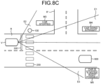
- the near display region E2 displays the display information M3 related to the current behavior of the vehicle directed toward the pedestrian 100 around the crosswalk 200, such as "CAR STOPPED".
- the far display region E1 displays the display information M4 related to the future behavior of the vehicle directed toward pedestrians other than the pedestrian 100 around the crosswalk 200, such as "CAR GOING STRAIGHT”.
- the oncoming vehicle display region E3 displays display information M5 including a message such as "CAR IS STOPPED, TURNING RIGHT POSSIBLE", which is different from the display related to the behavior of the vehicle visually recognizable by the pedestrian 100 around the crosswalk 200.
- the first light emitting unit group 21a emits light based on the display information M4 indicating "CAR GOING STRAIGHT”
- the second light emitting unit group 21b emits light based on the display information M3 indicating "CAR STOPPED”
- the third light emitting unit group 21c corresponding to the oncoming vehicle display region E3 emits light based on the display information M5 indicating "CAR IS STOPPED, TURNING RIGHT POSSIBLE".
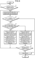
- FIG. 9 is a flowchart illustrating an example of control of the vehicle exterior display device according to the second embodiment. Since the basic operation of the vehicle exterior display device 1 according to the second embodiment is entirely or substantially the same as the vehicle exterior display device 1 according to the first embodiment, differences will be described below.
- the display controller 35 displays display information M1 related to the future behavior of the own vehicle at the far position in the far display region E1, the display information M2 related to the current behavior of the own vehicle at the far position in the near display region E2, and display information M5 different from the display related to the behavior of the vehicle visible by the pedestrian 100 around the crosswalk 200 at the far position in the oncoming vehicle display region E3 (step S9).
- the far display region E1 displays the display information M1 such as "CAR STOPPING" related to the future behavior of the own vehicle so that the pedestrian 100 at a far position with respect to the own vehicle V can determine whether the own vehicle V recognizes the pedestrian 100.
- the near display region E2 displays the display information M2, such as "CAR PASSING", directed for pedestrians other than the pedestrian 100 around the crosswalk 200 and for vehicles, which is different from the information displayed for the pedestrian 100 around the crosswalk 200.
- the oncoming vehicle display region E3 displays display information M5 such as "CAR PASSING", which is different from the display related to the behavior of the vehicle visually recognizable by the pedestrian 100 around the crosswalk 200.
- the first light emitting unit group 21a emits light based on the display information M1 indicating "CAR STOPPING”
- the second light emitting unit group 21b emits light based on the display information M2 indicating "CAR PASSING”
- the third light emitting unit group 21c corresponding to the oncoming vehicle display region E3 emits light based on the display information M5 indicating "CAR PASSING" (refer to FIG. 8A ).
- the display controller 35 calculates the positional relationship among the own vehicle V, the pedestrian 100, and the crosswalk 200 (step S2), determines that the own vehicle V is approaching the crosswalk 200 (step S3: Yes), and determines again whether the relative position between the own vehicle V and the pedestrian 100 is a far position (step S4).
- the display controller 35 maintains the display state of the display information M1 related to the future behavior of the own vehicle at the far position in the far display region E1, maintains the display state of the display information M2 related to the current behavior of the own vehicle at the far position in the near display region E2, and maintains the display state of the display information M5, which is different from the display related to the behavior of the vehicle visible by the pedestrian 100 around the crosswalk 200 at the far position, in the oncoming vehicle display region E3.
- the display controller 35 controls to display the display information M3 related to the current behavior of the own vehicle at the near position in the near display region E2, the display information M4 related to the future behavior of the own vehicle at the near position in the far display region E1, and the display information M5 different from the display related to the behavior of the vehicle visually recognizable by the pedestrian 100 around the crosswalk 200 at the near position, in the oncoming vehicle display region E3 (step S10).
- the near display region E2 displays the display information M3 such as "CAR STOPPED” related to the current behavior of the own vehicle so that the own vehicle V can determine whether the pedestrian 100 existing at the near position with respect to the own vehicle V can cross the crosswalk 200. Since the pedestrian 500, who is away from the vehicle V is concerned about the behavior taken by the automated driving vehicle, the display information M4 related to the future behavior of the vehicle such as "CAR STARTING” is displayed in the far display region E1 visually recognizable by the pedestrian 500 present farther away from the vehicle V. Moreover, the oncoming vehicle display region E3 displays the display information M5 such as "PEDESTRIAN IS CROSSING", which is different from the display related to the behavior of the vehicle visually recognizable by the pedestrian 100 existing around the crosswalk 200.
- the display information M3 such as "CAR STOPPED” related to the current behavior of the own vehicle so that the own vehicle V can determine whether the pedestrian 100 existing at the near position with respect to the own vehicle V can cross the crosswalk 200. Since the pedestrian 500, who is away
- the first light emitting unit group 21a emits light based on the display information M4 indicating "CAR STARTING”
- the second light emitting unit group 21b emits light based on the display information M3 indicating "CAR STOPPED”
- the third light emitting unit group 21c corresponding to the oncoming vehicle display region E3 emits light based on the display information M5 indicating "PEDESTRIAN IS CROSSING”. (refer to FIG. 8B ).
- the display controller 35 determines whether the pedestrian 100 is present around the crosswalk 200 based on the crosswalk position information X2 and the pedestrian position information X3 (step S11) Here, the display controller 35 determines whether the pedestrian 100 has crossed the crosswalk 200.
- step S11: Yes when having determined that the pedestrian 100 is present around the crosswalk 200 (step S11: Yes), the display controller 35 calculates a positional relationship among the own vehicle V, the pedestrian 100, and the crosswalk 200 (step S2), determines that the own vehicle V is approaching crosswalk 200 (step S3: Yes), and determines that the relative position between the own vehicle V and the pedestrian 100 is the near position (step S4: No).
- the display controller 35 maintains the display state of the display information M3 related to the current behavior of the vehicle at the near position in the near display region E2, maintains the display state of the display information M4 related to the future behavior of the own vehicle at the near position in the far display region E1, and maintains the display state of the display information M5, different from the display related to the behavior of the vehicle visually recognizable by the pedestrian 100 around the crosswalk 200 at the near position, in the oncoming vehicle display region E3.
- step S11 when having determined that there is no pedestrian 100 around the crosswalk 200 (step S11: No), the display controller 35 ends the display being performed by the display unit 20 (step S12).
- the vehicle exterior display device 1 described above is capable of performing display focused on the target of the message in accordance with the positional relationship between the own vehicle V and the oncoming vehicle, achieving transmission of useful information to the target.
- vehicle exterior display device 1 according to the first and second embodiments and the modifications described above is not limited to the above-described embodiments, and various modifications can be made within the scope described in the claims.
- vehicle V in the first and second embodiments and the modifications has been described as a vehicle capable of automated driving (semi-automated driving, fully automated driving), the type of vehicle V is not limited thereto.
- vehicle V may be a manually drivable vehicle in which the behavior of the vehicle V can be controlled according to the driving operation by the driver of the vehicle V.
- the display unit 20 according to each of the first and second embodiments and the modification has been described to display messages such as "CAR STOPPING" and "CAR STOPPED” as the display related to the behavior of the vehicle.
- the details of the display are not limited to this, and the messages may be displayed as graphics, symbols, histograms, or pictures other than the messages.
- the vehicle exterior display device has an effect of performing display focused on a target of the message according to a positional relationship between an own vehicle and a pedestrian and successfully transmitting useful information to the target.
Landscapes
- Engineering & Computer Science (AREA)
- Mechanical Engineering (AREA)
- Physics & Mathematics (AREA)
- General Physics & Mathematics (AREA)
- Theoretical Computer Science (AREA)
- Human Computer Interaction (AREA)
- General Engineering & Computer Science (AREA)
- Lighting Device Outwards From Vehicle And Optical Signal (AREA)
- Traffic Control Systems (AREA)
Abstract
Description
- The present invention relates to a vehicle exterior display device.
- Conventionally, a pedestrian who needs to cross a roadway using a crosswalk can predict whether a vehicle stops in front of the crosswalk by making eye contact or the like with a driver when the driver is on the vehicle located in front of the crosswalk. However, along with the emergence of vehicles capable of automated driving, there are many situations in which a vehicle traveling by automated driving without a driver drives through a crosswalk. In this case, when a pedestrian who needs to cross a roadway using a crosswalk is located in front of the crosswalk and a vehicle approaching toward the crosswalk is driving in automated driving, it is difficult for the pedestrian to predict whether the vehicle will stop in front of the crosswalk. For example, International Publication
WO 2017/073634 A discloses a technique in which an automated driving vehicle irradiates a road surface with a display of information indicating preliminary notification of stop to a pedestrian. - However, although the display of information indicating the preliminary notification of stop in International Publication
WO 2017/073634 A is presented to a pedestrian around a crosswalk, the display can also be viewed by pedestrians other than the pedestrian around the crosswalk, and thus, there is a possibility that the pedestrian other than the pedestrian around the crosswalk erroneously perceives the message as a message to himself/herself. - The present invention has been made in view of the above, and aims to provide a vehicle exterior display device capable of performing display focused on a target of the message according to a positional relationship between a pedestrian and an own vehicle, and achieving transmission of useful information to the target.
- In order to achieve the above mentioned object, a vehicle exterior display device according to one aspect of the present invention includes an own vehicle position information acquisition unit that acquires position information regarding an own vehicle; a crosswalk position information acquisition unit that acquires position information regarding a crosswalk; a surrounding information detection unit that detects a pedestrian around the own vehicle; a display unit that includes a plurality of display regions visually recognizable from outside of the own vehicle and is capable of displaying different types of display information visually recognizable by the display region; and a display controller that changes display information displayed by the display unit and the display region in which the display information is displayed, based on a positional relationship among the own vehicle, the crosswalk, and the pedestrian, wherein each of the plurality of display regions includes at least a far display region and a near display region, the display controller controls, out of the far display region and the near display region, the display region visible to the pedestrian existing around the crosswalk, to display display information related to behavior of a vehicle, and at least when a positional relationship between the vehicle and the pedestrian existing around the crosswalk is a far position, the display controller controls to perform display such that the display information displayed in the far display region and display information displayed in the near display region become different from each other.
- The above and other objects, features, advantages and technical and industrial significance of this invention will be better understood by reading the following detailed description of presently preferred embodiments of the invention, when considered in connection with the accompanying drawings.
-
-
FIG. 1 is a block diagram illustrating a schematic configuration of a vehicle exterior display device according to a first embodiment; -
FIG. 2 is a diagram illustrating an example of a display region setting method used by the vehicle exterior display device according to the first embodiment; -
FIG. 3 is a diagram illustrating a configuration of a display unit according to the first embodiment; -
FIG. 4A is a diagram illustrating a display region and display information when a relative position between an own vehicle and a pedestrian around a crosswalk is a far position according to the first embodiment; -
FIG. 4B is a diagram illustrating a display region and display information when a relative position between an own vehicle and a pedestrian around a crosswalk is a near position according to the first embodiment; -
FIG. 5 is a flowchart illustrating an example of control of the vehicle exterior display device according to the first embodiment; -
FIG. 6 is a diagram illustrating a display unit according to a modification; -
FIG. 7 is a diagram illustrating a configuration of a display unit according to a second embodiment; -
FIG. 8A is a diagram illustrating a display region and display information when a relative position between an own vehicle and a pedestrian around a crosswalk according to the second embodiment is a far position and there is an oncoming vehicle that needs to turn right; -
FIG. 8B is a diagram illustrating a display region and display information when a relative position between an own vehicle and a pedestrian around a crosswalk according to the second embodiment is a near position and there is an oncoming vehicle; -
FIG. 8C is a diagram illustrating a display region and display information when a relative position between an own vehicle and a pedestrian around a crosswalk according to the second embodiment is a near position and there is an oncoming vehicle that needs to turn right; and -
FIG. 9 is a flowchart illustrating an example of control of the vehicle exterior display device according to the second embodiment. - Hereinafter, exemplary embodiments of a vehicle
exterior display device 1 according to the present invention will be described in detail with reference to the drawings. Note that the present invention is not limited by the embodiments. -
FIG. 1 is a diagram illustrating a vehicle exterior display device according to the present invention.FIG. 2 is a diagram illustrating an example of a display region setting method used by a vehicle exterior display device according to the first embodiment.FIG. 3 is a diagram illustrating a configuration of a display unit according to the first embodiment.FIG. 4A is a diagram illustrating a display region and display information when a relative position between an own vehicle and a pedestrian is a far position according to the first embodiment.FIG. 4B is a diagram illustrating a display region and display information when the relative position between the own vehicle and the pedestrian is a near position according to the first embodiment. - The vehicle
exterior display device 1 is a display device that is applied to a vehicle V and performs various types of displays. The vehicle V to which the vehicleexterior display device 1 is applied may be any vehicle using a motor or an engine as a drive source, such as an electric vehicle (EV), a hybrid electric vehicle (HEV), a plug-in hybrid electric vehicle (PHEV), a gasoline vehicle, or a diesel vehicle. In addition, the driving of the vehicle V may be any of manual driving, semi-automated driving, fully automated driving, and the like, performed by the driver. Furthermore, the vehicle V may be any of a private car owned by an individual, a rental car, a sharing car, a bus, a taxi, and a ride sharing car. - In the following description, as an example, the vehicle V will be described as a vehicle capable of automated driving (including semi-automated driving and fully automated driving). The vehicle
exterior display device 1 assumes implementation of driving referred to as automated driving by the vehicle V, and based on this assumption, implements appropriate display related to the behavior of the vehicle according to the positional relationship with persons outside the vehicle V. The vehicleexterior display device 1 is implemented by mounting the components illustrated inFIG. 1 on the vehicle V. Hereinafter, each configuration of the vehicleexterior display device 1 will be described in detail with reference toFIG. 1 . In the following description, the vehicle V may be referred to as an "own vehicle V". - Note that, in the vehicle
exterior display device 1 illustrated inFIG. 1 , the connection method between individual components for supplying power, transmitting and receiving control signals, various types of information, and the like may be any of wired connection (including optical communication via an optical fiber, for example) via a wiring material such as an electric wire or an optical fiber, and wireless connection such as radio communication or contactless power feeding, unless otherwise specified. - Specifically, the vehicle
exterior display device 1 includes adetection unit 10, adisplay unit 20, and acontrol unit 30. - First, the
detection unit 10 will be described. Thedetection unit 10 is implemented by equipping the vehicle V with the components illustrated inFIG. 1 . Specifically, thedetection unit 10 includes aGPS receiver 11, atraveling system actuator 12, avehicle state detector 13, acommunication module 14, anexternal camera 15, and anexternal radar 16. - The
GPS receiver 11 detects current position information indicating the current position of the vehicle V, that is, own vehicle position information X1, as surrounding status information. TheGPS receiver 11 receives a radio wave transmitted from a GPS satellite to acquire GPS information (latitude and longitude coordinates) of the vehicle V as the own vehicle position information X1. Thetraveling system actuator 12 includes various devices needed for the vehicle V to travel. Thetraveling system actuator 12 typically includes a traveling powertrain, a steering device, a braking device, and the like. The traveling powertrain is a driving device that drives the vehicle V. The steering device is a device that steers the vehicle V. The braking device is a device that brakes the vehicle V. Thevehicle state detector 13 detects vehicle state information including vehicle speed information, acceleration information, steering angle information, accelerator pedal operation amount information, brake pedal operation amount information, shift position information, current value/voltage value information, and charge amount information. Thevehicle state detector 13 includes, for example, various detectors and sensors such as a vehicle speed sensor, an acceleration sensor, a steering angle sensor, an accelerator sensor, a brake sensor, a shift position sensor, and an ammeter/voltmeter. Thevehicle state detector 13 may include an entire processing unit such as an electronic control unit (ECU) that controls individual components in the vehicle V. Thecommunication module 14 transmits and receives information by radio communication to and from an external device of the vehicle V, such as another vehicle, an on-road device, a cloud device, or an electronic device possessed by a person outside the vehicle V. With this configuration, thecommunication module 14 detects surrounding status information including, for example, surrounding image information, external object information, traffic information, and the own vehicle position information X1. Thecommunication module 14 communicates with an external device by various types of radio communication such as wide-range radio communication and narrow-range radio communication. Here, examples of the wide-range radio communication system include radio broadcasting (AM, FM), TV (UHF, 4K, 8K), telephone, GPS, and WiMAX (registered trademark). In addition, examples of the narrow-range radio communication system include ETC/DSRC, VICS (registered trademark), wireless LAN, and millimeter wave communication. Theexternal camera 15 captures an image of the surroundings of the vehicle V constituting the surrounding image information and an image of a traveling road surface of the vehicle V constituting the white line information, as the surrounding status information. Theexternal radar 16 detects, as the surrounding status information, external object information using infrared rays, millimeter waves, ultrasonic waves, or the like. - The
display unit 20, provided on the vehicle V, has a plurality of display regions E, specifically two display regions E1 and E2 in the present embodiment, which can be visually recognized from the outside of the own vehicle V, and it is possible to display different display information M each of which is visually recognizable by the display regions E1 and E2. In the present embodiment, thedisplay unit 20 is installed outside or inside the cabin in front of the vehicle V, and includes: a far display region E1 that is a region in which display is performed toward a far front of the vehicle V, particularly a far front left side in the case of left-hand traffic; and a near display region E2 that is a region adjacent to the far display region E1 and a region in which display is performed toward a near front of the vehicle V, particularly a near front left side in the case of left-hand traffic. Here, each of the display regions E1 and E2 is in a range in which the display of thedisplay unit 20 is visible only by a specific pedestrian, having a display angle that can be displayed from thedisplay unit 20. Each of the display regions E1 and E2 of the present embodiment changes display information M to be displayed according to the relative position between the own vehicle V and apedestrian 100 around acrosswalk 200. For example, as illustrated inFIG. 2 , a method of calculating the far display region E1 when assuming a vehicle traveling on a local road at a speed of 60 km/h will be described. A solid line S1 represents a deceleration profile when the vehicle V stops at a deceleration that does not make the occupant feel uncomfortable, and a dotted line S2 represents a relationship between a distance and a speed at which the vehicle V stops by sudden braking. Assuming a case where the vehicle V decelerates at a deceleration that does not make the occupant feel uncomfortable and the display is started on thedisplay unit 20 at aposition 25 meters in front of the vehicle stop position, the distance needed for the vehicle V to stop by sudden braking at the speed at a stop start time point is about 11 meters. When the traveling direction of the vehicle V is a forward direction, and a pedestrian present within 4 meters from the center cross section of the vehicle V in the left-right direction and present within 11 meters in front of the vehicle V rushes out, it would not be possible to avoid a collision. Therefore, it is desirable that the region is not visible to the pedestrian present in this range. In view of this, the far display region E1 is set based on Formula (1).
- The method of determining Θ is an example, and there is no restriction regarding the friction coefficient between the tire and the road surface, the assumed vehicle speed, deceleration, a deceleration start position, or the like. In addition, the determination may be made in consideration of parameters that affect a range in which the vehicle can be safely stopped, such as a road surface condition, weather, and accuracy of various sensors. Furthermore, the determination may be made in consideration of the influence of discomfort or the like on the occupant of the automated driving vehicle when the vehicle decelerates.
- As illustrated in
FIG. 3 , thedisplay unit 20 includes alight emitting unit 21,lenses 22, acover 23, acase 24, and asubstrate 25. Thelight emitting unit 21 in the present embodiment is be to be mounted on thesubstrate 25 and arranged in plurality on a plane. Thelight emitting unit 21 in the present embodiment includes a plurality of light emittingunit groups lenses 22. The plurality of light emittingunit groups unit group 21a corresponding to the far display region E1 and a second light emittingunit group 21b corresponding to the near display region E2. The first light emittingunit group 21a includes a plurality of firstlight emitting units 211, and the second light emittingunit group 21b includes a plurality of secondlight emitting units 212. The firstlight emitting unit 211 is disposed corresponding to eachlens 22, and is disposed at the center with respect to eachlens 22 in the present embodiment. The secondlight emitting unit 212 is disposed corresponding to eachlens 22, and is disposed in a state of being adjacent to the firstlight emitting unit 211, at one of both ends with respect to eachlens 22 in the present embodiment. The first light emittingunit group 21a and the second light emittingunit group 21b are disposed alternately and emit light corresponding to the display information M related to the behavior of the own vehicle V. The display information M related to the behavior of own vehicle V is displayed as the display information M that changes according to display region E. Therefore, the first light emittingunit group 21a and the second light emittingunit group 21b emit light based on mutually different pieces of display information M. Specifically, when the relative position between the own vehicle V and thepedestrian 100 around thecrosswalk 200 is a far position, the first light emittingunit group 21a corresponding to the far display region E1 emits light for displaying the display information M1 related to future vehicle behavior corresponding to the far position, while the second light emittingunit group 21b corresponding to the near display region E2 emits light for displaying display information M2 related to current vehicle behavior corresponding to the far position. However, in a case where the relative position between the own vehicle V and thepedestrian 100 around thecrosswalk 200 is changed to the near position, information related to the behavior of the own vehicle V that thepedestrian 100 around thecrosswalk 200 wants to know becomes different in the display information M from the case where the relative position between the own vehicle V and thepedestrian 100 around thecrosswalk 200 is the far position. Accordingly, when the relative position between the own vehicle V and thepedestrian 100 around thecrosswalk 200 is changed to the near position, the first light emittingunit group 21a corresponding to the far display region E1 emits light for displaying display information M4 related to future vehicle behavior corresponding to the near position, while the second light emittingunit group 21b corresponding to the near display region E2 emits light for displaying display information M3 related to current vehicle behavior corresponding to the near position. In this manner, the first light emittingunit group 21a and the second light emittingunit group 21b emit light based on mutually different pieces of display information M according to the positional relationship between the vehicle V and thepedestrian 100 around thecrosswalk 200. Thelens 22 has a semicircular cross section and transmits light from thelight emitting unit 21. Thelens 22 has different positions where light from thelight emitting unit 21 is visually recognizable due to refraction of light according to an angle viewed from the outside of the vehicle V. Thecover 23 has transparency and allows light from thelight emitting unit 21 to be visually recognized from the outside of the vehicle V. Thecase 24 surrounds thelight emitting unit 21 and thelens 22, and thecover 23 is fitted to the outside of the vehicle V of thecase 24. - As illustrated in
FIG. 1 , thecontrol unit 30 integrally controls individual components of the vehicleexterior display device 1. Thecontrol unit 30 may also be incorporated as an electronic control unit that integrally controls the entire vehicle V. Thecontrol unit 30 executes various types of arithmetic processing for implementation of traveling of the vehicle V. Thecontrol unit 30 includes an electronic circuit mainly including a known microcomputer, including a central processing device such as a central processing unit (CPU), a micro processing unit (MPU), an application specific integrated circuit (ASIC), and a field programmable gate array (FPGA), and including read only memory (ROM), random access memory (RAM), and an interface. Thecontrol unit 30 is electrically connected to thedetection unit 10 and thedisplay unit 20. Thecontrol unit 30 may be electrically connected with thedetection unit 10 and thedisplay unit 20 via an ECU (for example, a body ECU) that controls individual components of the vehicle V. Thecontrol unit 30 can exchange, with individual components, various electric signals such as various detection signals and a drive signal for driving the individual components. - Specifically, the
control unit 30 functionally and conceptually includes aninterface unit 31, an own vehicle positioninformation acquisition unit 32, a crosswalk positioninformation acquisition unit 33, a surroundinginformation acquisition unit 34, adisplay controller 35, and astorage unit 36. Theinterface unit 31, the own vehicle positioninformation acquisition unit 32, the crosswalk positioninformation acquisition unit 33, the surroundinginformation acquisition unit 34, thedisplay controller 35, and thestorage unit 36 can exchange various types of information with various types of electrically connected devices. - The
interface unit 31 is an interface for transmitting and receiving various types of information to and from individual components such as a detection unit. Furthermore, theinterface unit 31 is electrically connectable to thedetection unit 10, the own vehicle positioninformation acquisition unit 32, the crosswalk positioninformation acquisition unit 33, and the surroundinginformation acquisition unit 34. Theinterface unit 31 has functions such as a function of performing wired communication of transferring information with individual components via an electric wire or the like and a function of performing wireless communication of information with individual components via a radio communication unit and the like. - The own vehicle position
information acquisition unit 32 acquires the own vehicle position information X1. The own vehicle positioninformation acquisition unit 32 acquires the own vehicle position information X1 based on information received by theGPS receiver 11, for example. - The crosswalk position
information acquisition unit 33 acquires position information regarding thecrosswalk 200. For example, the crosswalk positioninformation acquisition unit 33 acquires crosswalk position information X2 that is position information regarding thecrosswalk 200 existing in the traveling direction of the own vehicle V based on the own vehicle position information X1 and map information stored in advance in thestorage unit 36. For example, the crosswalk positioninformation acquisition unit 33 may acquire the crosswalk position information X2 based on a surrounding image of the own vehicle V captured by theexternal camera 15. Furthermore, the crosswalk positioninformation acquisition unit 33 may acquire the crosswalk position information X2 based on the own vehicle position information X1 and map information stored outside the own vehicle V acquired by thecommunication module 14. - The surrounding
information acquisition unit 34 acquires information around the own vehicle V. The surroundinginformation acquisition unit 34 in the present embodiment acquires information related to thepedestrian 100 being a viewer of thedisplay unit 20 and existing around the own vehicle V. For example, the surroundinginformation acquisition unit 34 may acquire pedestrian position information X3 existing around the own vehicle V based on the surrounding image of the own vehicle V captured by theexternal camera 15. Furthermore, for example, the pedestrian position information X3 may be acquired based on surrounding objects of the own vehicle V scanned and detected by theexternal radar 16. - The
display controller 35 controls the display information M regarding the behavior of the own vehicle V displayed on thedisplay unit 20 in the far display region E1 and the near display region E2 of thedisplay unit 20. Thedisplay controller 35 of the present embodiment changes the display information M related to the behavior of the own vehicle V in the display region E of thedisplay unit 20 according to the relative position between the own vehicle V and the surroundingpedestrian 100 based on the positional relationship among the own vehicle position information X1 acquired by the own vehicle positioninformation acquisition unit 32, the crosswalk position information X2 acquired by the crosswalk positioninformation acquisition unit 33, and the pedestrian position information X3 acquired by the surroundinginformation acquisition unit 34. Specifically, the positional relationship between thecrosswalk 200 and thepedestrian 100 is calculated based on the crosswalk position information X2 acquired by the crosswalk positioninformation acquisition unit 33 and based on the pedestrian position information X3 acquired by the surroundinginformation acquisition unit 34, and determination is made whether thepedestrian 100 is located around thecrosswalk 200, that is, whether thepedestrian 100 exists around thecrosswalk 200. Regarding the determination thatpedestrian 100 exits around thecrosswalk 200, it is allowable to determine that thepedestrian 100 is about to cross thecrosswalk 200 by determining thatpedestrian 100 is located around thecrosswalk 200, further determining whether the face or body direction ofpedestrian 100 is directed toward thecrosswalk 200, and determining thatpedestrian 100 is directed toward thecrosswalk 200. When it is determined that thepedestrian 100 is located around thecrosswalk 200 and thepedestrian 100 is about to cross thecrosswalk 200, the positional relationship between thepedestrian 100 and the own vehicle V around thecrosswalk 200 is calculated based on the own vehicle position information X1 acquired by the own vehicle positioninformation acquisition unit 32 and the pedestrian position information X3 acquired by the surroundinginformation acquisition unit 34. When it is determined that the relative position between thepedestrian 100 and the own vehicle V around thecrosswalk 200 is the far position, the display information M1 regarding future behavior of the own vehicle according to the far position is displayed in the far display region E1 of thedisplay unit 20 while the display information M2 regarding current behavior of the own vehicle according to the far position is displayed in the near display region E2. Furthermore, based on the own vehicle position information X1 acquired by the own vehicle positioninformation acquisition unit 32 and the pedestrian position information X3 acquired by the surroundinginformation acquisition unit 34, the positional relationship between thepedestrian 100 around thecrosswalk 200 and the own vehicle V is calculated. When it is determined that the relative position between thepedestrian 100 around thecrosswalk 200 and the own vehicle V is the near position, the display information M3 related to the current behavior of the own vehicle according to the near position is displayed on thedisplay unit 20 in the near display region E2 of thedisplay unit 20, and the display information M4 related to the future behavior of the own vehicle according to the near position is displayed in the far display region E1. - For example, in a case where the vehicle V is traveling on a road R, and when the
display controller 35 has determined that the relative position between the own vehicle V and thepedestrian 100 present around thecrosswalk 200 is a far position based on the crosswalk position information X2 acquired by the crosswalk positioninformation acquisition unit 33 and the pedestrian position information X3 acquired by the surroundinginformation acquisition unit 34 as illustrated inFIG. 4A , thedisplay controller 35 performs display of the display information M1 such as "CAR STOPPING" related to the future behavior of the vehicle toward thepedestrian 100 present around thecrosswalk 200, as the display information M displayed in the far display region E1 of thedisplay unit 20. This enables thepedestrian 100 who is located around thecrosswalk 200 and is about to cross thecrosswalk 200 to visually recognize the display of thedisplay unit 20. However, when anotherpedestrian 400 is present at a position closer to the vehicle V than thepedestrian 100 present around thecrosswalk 200, thepedestrian 400 present at a position closer to the vehicle V than thepedestrian 100 present around thecrosswalk 200 might erroneously perceive that the display is made for thepedestrian 400 oneself, even though the display is made for thepedestrian 100 present around thecrosswalk 200. Therefore, the near display region E2 performs a display of display information M2 regarding the current behavior of the vehicle, such as "CAR PASSING" directed for thepedestrian 400 present at a position closer to the vehicle V than thepedestrian 100 present around thecrosswalk 200, which is different from the display information M for thepedestrian 100 present around thecrosswalk 200. At this time, the first light emittingunit group 21a emits light based on the display information M1 indicating "CAR STOPPING", while a second light emittingunit group 21b emits light based on the display information M2 indicating "CAR PASSING". As illustrated inFIG. 4B , when the vehicle V being an unmanned automated driving vehicle stops in front of thecrosswalk 200, the relative position between the own vehicle V and thepedestrian 100 around thecrosswalk 200 has changed to the near position as compared withFIG. 4A . Therefore, the display information M displayed in the near display region E2 of thedisplay unit 20 is made by displaying the message "CAR STOPPED", which is display information M3 related to the current behavior of the vehicle toward thepedestrian 100 around thecrosswalk 200. Since apedestrian 500, who is farther away from the vehicle V than thepedestrian 100 present around thecrosswalk 200, is concerned about the behavior taken by the automated driving vehicle, the display information M4 regarding the future behavior of the vehicle such as "CAR MOVING" is displayed in the far display region E1 visually recognizable by thepedestrian 500 present farther away from the vehicle V. At this time, the first light emittingunit group 21a emits light based on the display information M4 indicating "CAR MOVING", while the second light emittingunit group 21b emits light based on the display information M3 indicating "CAR STOPPED". - The
storage unit 36 is a device that stores data related to the behavior of the own vehicle. Thestorage unit 36 may be, for example, a relatively large-capacity storage device such as a hard disk, a solid state drive (SSD), or an optical disk, or may be data rewritable semiconductor memory such as RAM, flash memory, or nonvolatile static random access memory (NVSRAM). Thestorage unit 36 stores conditions and information necessary for various processes in thecontrol unit 30, various programs and applications executed by the control unit, control data, and the like. Thestorage unit 36 stores, for example, the display information M related to the behavior of the own vehicle V displayed on thedisplay unit 20 controlled by thedisplay controller 35.Storage unit 36 can also temporarily store various types of information acquired by the own vehicle positioninformation acquisition unit 32, the crosswalk positioninformation acquisition unit 33, and the surroundinginformation acquisition unit 34, for example. The information in thestorage unit 36 is read by thedisplay controller 35 as necessary. - Next, an outline of an operation of the vehicle
exterior display device 1 will be described.FIG. 5 is a flowchart illustrating an example of control of the vehicle exterior display device according to the first embodiment. - First, the
display controller 35 determines whether thepedestrian 100 is present around thecrosswalk 200 based on the pedestrian position information X3 and the crosswalk position information X2 (step S1). Specifically, a positional relationship between thecrosswalk 200 and thepedestrian 100 is calculated based on the crosswalk position information X2 acquired by the crosswalk positioninformation acquisition unit 33 and the pedestrian position information X3 acquired by the surroundinginformation acquisition unit 34, and a determination is made as to whether there is thepedestrian 100 who is about to cross thecrosswalk 200. Thedisplay controller 35 determines thatpedestrian 100 is about to cross thecrosswalk 200 when the face or body of thepedestrian 100 is directed toward thecrosswalk 200 or when the movement locus of thepedestrian 100 is directed toward thecrosswalk 200. - When having determined that
pedestrian 100 is not present around the crosswalk 200 (step S1: No), thedisplay controller 35 repeats step S1 until thepedestrian 100 is present around thecrosswalk 200. - When having determined that
pedestrian 100 is present around the crosswalk 200 (step S1: Yes), thedisplay controller 35 calculates the positional relationship among the own vehicle V, thecrosswalk 200, and thepedestrian 100 based on the own vehicle position information X1, the crosswalk position information X2, and the pedestrian position information X3 (step S2). - Next, the
display controller 35 determines whether the own vehicle V is approaching thecrosswalk 200 based on the own vehicle position information X1 and the crosswalk position information X2 (step S3). - When having determined that the own vehicle V is approaching the crosswalk 200 (step S3: Yes), the
display controller 35 determines whether the relative position between the own vehicle V and thepedestrian 100 is a far position based on the own vehicle position information X1 and the pedestrian position information X3 (step S4). - When having determined that the relative position between the own vehicle V and the
pedestrian 100 is the far position (step S4: Yes), thedisplay controller 35 displays the display information M1 related to the future behavior of the own vehicle at the far position in the far display region E1 and the display information M2 related to the current behavior of the own vehicle at the far position in the near display region E2 (step S5). For example, in order to enable thepedestrian 100 at the far position with respect to the own vehicle V to determine whether the own vehicle V recognizes thepedestrian 100, thedisplay controller 35 causes the first light emittingunit group 21a corresponding to the near display region E2 to perform light emission for displaying the display information M1 related to the future behavior of the vehicle at the far position so as to achieve display of the display information M1 related to the future behavior of the own vehicle such as "CAR STOPPING". However, when thepedestrian 400 is present at a position closer to the own vehicle V than thepedestrian 100 present around thecrosswalk 200, thepedestrian 400 present at a position closer to the own vehicle V than thepedestrian 100 present around thecrosswalk 200 might erroneously perceive that the display is made for thepedestrian 400 oneself, even though the display is made for thepedestrian 100 present around thecrosswalk 200. To handle this, the second light emittingunit group 21b corresponding to the near display region E2 is controlled to emit light for displaying the display information M2 related to the current behavior of the vehicle according to the far position, and display is performed in the near display region, toward thepedestrian 400 other than thepedestrian 100 present around thecrosswalk 200, such as "CAR PASSING", as a different display from the information to be displayed for thepedestrian 100 present around the crosswalk 200 (refer toFIG. 4A ). - Next, the
display controller 35 calculates the positional relationship among the own vehicle V, thepedestrian 100, and the crosswalk 200 (step S2), determines that the own vehicle V is approaching the crosswalk 200 (step S3: Yes), and determines again whether the relative position between the own vehicle V and thepedestrian 100 is a far position (step S4). With this configuration, when thepedestrian 100 remains at the far position with respect to the own vehicle V, thedisplay controller 35 maintains the display state of the display information M1 related to the future behavior of the own vehicle V at the far position in the far display region E1, and maintains the display state of the display information M2 related to the current behavior of the own vehicle V at the far position in the near display region E2. - When having determined that the relative position between own vehicle V and
pedestrian 100 is not the far position, that is, the relative position is the near position (step S4: No), thedisplay controller 35 causes the near display region E2 to display the display information M3 related to the current behavior of the own vehicle V at the near position and causes the far display region E1 to display the display information M4 related to the future behavior of the own vehicle at the near position (step S6). For example, in order to enable determination as to whether thepedestrian 100 located at a near position with respect to the own vehicle V can cross thecrosswalk 200, thedisplay controller 35 performs light emission for displaying the display information M3 related to the current behavior of the vehicle corresponding to the near position in the second light emittingunit group 21b corresponding to the near display region E2, so as to perform display of the display information M3 related to the current behavior of the own vehicle such as "CAR STOPPED". Thepedestrian 500 who is away from the vehicle V is concerned about the behavior of the automated driving vehicle, and thus, light emission for displaying the display information M4 regarding the future behavior of the vehicle according to the near position is performed in the second light emittingunit group 21b corresponding to the far display region E1, so as to perform display of the display information M4 regarding the future behavior of the vehicle such as "CAR MOVING" in the far display region E1 visually recognizable from thepedestrian 500 who is away from the vehicle V (refer toFIG. 4B ). - Next, the
display controller 35 determines whether thepedestrian 100 is present around thecrosswalk 200 based on the crosswalk position information X2 and the pedestrian position information X3 (step S7). Here, thedisplay controller 35 determines whether thepedestrian 100 has crossed thecrosswalk 200. - Next, when having determined that the
pedestrian 100 is present around the crosswalk 200 (step S7: Yes), thedisplay controller 35 calculates the positional relationship among the own vehicle V, thepedestrian 100, and the crosswalk 200 (step S2), determines that the own vehicle V is approaching the crosswalk 200 (step S3: Yes), and determines that the relative position between the own vehicle V and thepedestrian 100 is the near position (step S4: No). With this configuration, when thepedestrian 100 remains in the near position with respect to the own vehicle V, thedisplay controller 35 maintains the display state, in the near display region E2, of the display information M3 related to the current behavior of the vehicle in the near position, and maintains the display state, in the far display region E1, of the display information M4 related to the future behavior of the own vehicle in the near position. - Next, when having determined that there is no
pedestrian 100 around the crosswalk 200 (step S7: No), thedisplay controller 35 ends the display being performed by the display unit 20 (step S8). - In the vehicle
exterior display device 1 described above, even with the change in the relative position between the own vehicle V and thepedestrian 100, thepedestrian 100 around thecrosswalk 200 can always visually recognize the display of thedisplay unit 20, making it possible to visually recognize an appropriate message related to the behavior of the own vehicle V according to the relative position between the own vehicle V and thepedestrian 100. In addition, thepedestrians pedestrian 100 present around thecrosswalk 200 visually recognize the display information M related to the behavior of the own vehicle V different from the information for thepedestrian 100 present around thecrosswalk 200, making it possible to determine the behavior of the own vehicle V based on the display information M related to the behavior of the own vehicle V provided to the other pedestrians, namely, thepedestrians pedestrians pedestrian 100 around thecrosswalk 200 are capable of acting based on the display information M regarding the behavior of the own vehicle V provided to themselves, making it possible to maintain the safety in the relationship with the own vehicle V. That is, the vehicleexterior display device 1 is capable of performing display focused on the target of the message in accordance with the positional relationship between the own vehicle V and thepedestrians - In addition, the vehicle
exterior display device 1 controls the display that is performed by emission of thelight emitting unit 21 in thedisplay unit 20 according to whether the relative position between the own vehicle V and thepedestrian 100 around thecrosswalk 200 is the far position or the near position, and changes the display information M of the display region E of thedisplay unit 20 accordingly. This makes it possible for the vehicleexterior display device 1 to set a plurality of display regions E1 and E2 in onedisplay unit 20. - In addition, by providing, in the vehicle
exterior display device 1, the plurality of light emittingunit groups pedestrian 100 present around thecrosswalk 200, it is possible to visually recognize different displays depending on the angle when viewed from the outside of the vehicle. - Although the present embodiment has been described as a case of including the
light emitting unit 21 and thelens 22, the configuration is not limited to this case.FIG. 6 is a diagram illustrating a display unit according to a modification. Alight shielding member 26 is provided with a plurality ofopenings 26a each of which being formed corresponding to each of thelight emitting units 21. Theopening 26a is formed in such a size that would not allow a pedestrian to visually recognize light from a light emitting unit group adjacent to the corresponding light emitting unit group in the far display region E1 and the near display region E2. Thelight emitting unit 21 in the modification includes a plurality of light emitting unit groups each corresponding to theopening 26a. The plurality of light emitting unit groups has a configuration including: a first light emittingunit group 21a corresponding to the far display region E1; and a second light emittingunit group 21b corresponding to the near display region E2, in which the first light emittingunit group 21a and the second light emittingunit group 21b are alternately arranged. Specifically, the pedestrian located in the far display region E1 can visually recognize the light emission of the corresponding first light emittingunit group 21a, and thus can visually recognize the display of the display information M based on the light emission of the first light emittingunit group 21a, while the pedestrian located in the near display region E2 can visually recognize the light emission of the corresponding second light emittingunit group 21b, and thus can visually recognize the display of the display information M based on the light emission of the second light emittingunit group 21b. - The vehicle
exterior display device 1 according to the modification has different types of light emitting unit groups visible from an opening 22e in accordance with the relative position between the own vehicle V and thepedestrian 100 around thecrosswalk 200, so as to allow the display information corresponding to the relative position between the own vehicle and the pedestrian to be visually recognized. - The
light shielding member 26 in the modification has been described as having the plurality ofopenings 26a corresponding to thelight emitting units 21, but may be replaced with a transmissive liquid crystal panel. - Next, a vehicle exterior display device according to a second embodiment will be described.
FIG. 7 is a diagram illustrating a configuration of thedisplay unit 20 of the second embodiment.FIG. 8A is a diagram illustrating a display region and display information when a relative position between an own vehicle and a pedestrian around a crosswalk according to the second embodiment is a far position and there is an oncoming vehicle that needs to turn right.FIG. 8B is a diagram illustrating a display region and display information when a relative position between an own vehicle and a pedestrian around a crosswalk according to the second embodiment is a near position and there is an oncoming vehicle.FIG. 8C is a diagram illustrating a display region and display information when a relative position between an own vehicle and a pedestrian around a crosswalk according to the second embodiment is a near position and there is an oncoming vehicle that needs to turn right. The vehicleexterior display device 1 according to the second embodiment further includes an oncoming vehicle display region E3 added to the display region E of the vehicleexterior display device 1 according to the first embodiment. Since the basic configuration of the vehicleexterior display device 1 according to the second embodiment is entirely or substantially the same as the vehicleexterior display device 1 according to the first embodiment, differences will be described below. - The display region E of the
display unit 20 includes a far display region E1, a near display region E2, and an oncoming vehicle display region E3. The display region E has a configuration in which the far display region E1 is disposed between the near display region E2 and the oncoming vehicle display region E3. Thelight emitting unit 21 includes a plurality of light emittingunit groups lens 22 individually. The plurality of light emittingunit groups unit group 21a corresponding to the far display region E1, the second light emittingunit group 21b corresponding to the near display region E2, and the third light emittingunit group 21c corresponding to the oncoming vehicle display region E3, respectively, in which the third light emittingunit group 21c includes a plurality of thirdlight emitting units 213. The thirdlight emitting unit 213 is disposed corresponding to eachlens 22, and is disposed in a state of being adjacent to the firstlight emitting unit 211, at the other end out of both ends with respect to eachlens 22, in the present embodiment. The third light emittingunit group 21c performs light emission corresponding to the display information M related to the behavior of the own vehicle V different from or the same as the display information M of the first light emittingunit group 21a and the second light emittingunit group 21b. The oncoming vehicle display region E3 is a display region that performs display different from the display related to the behavior of the vehicle visually recognizable by thepedestrian 100 around thecrosswalk 200. Specifically, as illustrated inFIG. 8A , when the relative position between the own vehicle V and thepedestrian 100 around thecrosswalk 200 is the far position, and when there is anoncoming vehicle 600 that needs to turn to a road R' connected to a road R on which the own vehicle V travels, that is, needs to turn right, the far display region E1 displays the display information M1 related to the future behavior of the vehicle directed toward thepedestrian 100 around thecrosswalk 200, such as "CAR STOPPING". In addition, the near display region E2 is a display region that displays the display information M2 regarding the behavior of the current vehicle, such as "CAR PASSING", which is directed for amerging waiting vehicle 700 that needs to merge into the road R from the road R' and is at a position closer to the vehicle V than the position of thepedestrian 100 around thecrosswalk 200 and which is different from the display information M1 for thepedestrian 100 around thecrosswalk 200. On the other hand, when there is theoncoming vehicle 600 that needs to turn right, the driver riding on theoncoming vehicle 600 might erroneously perceive that the display is made for theoncoming vehicle 600 although the display is actually made for thepedestrian 100 present around thecrosswalk 200. To handle this, the oncoming vehicle display region E3 displays display information M5 including a display such as "CAR PASSING", which is different from the display related to the behavior of the vehicle visually recognizable by thepedestrian 100 around thecrosswalk 200. At this time, the first light emittingunit group 21a emits light based on the display information M1 indicating "CAR STOPPING", the second light emittingunit group 21b emits light based on the display information M2 indicating "CAR PASSING", and the third light emittingunit group 21c corresponding to the oncoming vehicle display region E3 emits light based on the display information M5 indicating "CAR PASSING". As illustrated inFIG. 8B , when the relative position between the own vehicle V and thepedestrian 100 around thecrosswalk 200 is the near position, and when there is theoncoming vehicle 600 that need to turn right, the near display region E2 displays the display information M3 such as "CAR STOPPED" related to the current behavior of the vehicle directed toward thepedestrian 100 around thecrosswalk 200. In addition, the display information M4 related to future vehicle behavior such as "CAR STARTING" is displayed for thepedestrian 500 who is farther away from the vehicle V than thepedestrian 100 around thecrosswalk 200. Moreover, the oncoming vehicle display region E3 displays display information M4 such as "PEDESTRIAN IS CROSSING", which is different from the display information M3 related to the behavior of the vehicle visually recognizable by thepedestrian 100 around thecrosswalk 200. At this time, the first light emittingunit group 21a emits light based on the display information M4 indicating "CAR STARTING", the second light emittingunit group 21b emits light based on the display information M3 indicating "CAR STOPPED", and the third light emittingunit group 21c corresponding to the oncoming vehicle display region E3 emits light based on the display information M5 indicating "PEDESTRIAN IS CROSSING". With this configuration, the oncomingvehicle 600 notices the existence of thepedestrian 100 crossing thecrosswalk 200 and can stop in front of thecrosswalk 200. In addition, as illustrated inFIG. 8C , when the relative position between the own vehicle V and thepedestrian 100 around thecrosswalk 200 is the near position, and when there is theoncoming vehicle 600 that needs to turn to the road R' connected to the road R on which the own vehicle V travels, that is, needs to turn right, the near display region E2 displays the display information M3 related to the current behavior of the vehicle directed toward thepedestrian 100 around thecrosswalk 200, such as "CAR STOPPED". Furthermore, the far display region E1 displays the display information M4 related to the future behavior of the vehicle directed toward pedestrians other than thepedestrian 100 around thecrosswalk 200, such as "CAR GOING STRAIGHT". On the other hand, when there is theoncoming vehicle 600 that needs to turn right, the driver riding on theoncoming vehicle 600 might erroneously perceive that the display is made for theoncoming vehicle 600 although the display is actually made for thepedestrian 100 present around thecrosswalk 200 and might then have to wait until the own vehicle V passes through. To handle this, the oncoming vehicle display region E3 displays display information M5 including a message such as "CAR IS STOPPED, TURNING RIGHT POSSIBLE", which is different from the display related to the behavior of the vehicle visually recognizable by thepedestrian 100 around thecrosswalk 200. At this time, the first light emittingunit group 21a emits light based on the display information M4 indicating "CAR GOING STRAIGHT", the second light emittingunit group 21b emits light based on the display information M3 indicating "CAR STOPPED", and the third light emittingunit group 21c corresponding to the oncoming vehicle display region E3 emits light based on the display information M5 indicating "CAR IS STOPPED, TURNING RIGHT POSSIBLE". This makes it possible to perform display focused on the target of the message in accordance with the positional relationship between the own vehicle V and the oncoming vehicle, achieving transmission of useful information to the target. - Next, an outline of an operation of the vehicle
exterior display device 1 will be described.FIG. 9 is a flowchart illustrating an example of control of the vehicle exterior display device according to the second embodiment. Since the basic operation of the vehicleexterior display device 1 according to the second embodiment is entirely or substantially the same as the vehicleexterior display device 1 according to the first embodiment, differences will be described below. - When having determined that the relative position between the own vehicle V and the
pedestrian 100 is the far position (step S4: Yes), thedisplay controller 35 displays display information M1 related to the future behavior of the own vehicle at the far position in the far display region E1, the display information M2 related to the current behavior of the own vehicle at the far position in the near display region E2, and display information M5 different from the display related to the behavior of the vehicle visible by thepedestrian 100 around thecrosswalk 200 at the far position in the oncoming vehicle display region E3 (step S9). For example, the far display region E1 displays the display information M1 such as "CAR STOPPING" related to the future behavior of the own vehicle so that thepedestrian 100 at a far position with respect to the own vehicle V can determine whether the own vehicle V recognizes thepedestrian 100. The near display region E2 displays the display information M2, such as "CAR PASSING", directed for pedestrians other than thepedestrian 100 around thecrosswalk 200 and for vehicles, which is different from the information displayed for thepedestrian 100 around thecrosswalk 200. In addition, when there is theoncoming vehicle 600 that needs to turn right, the driver riding on theoncoming vehicle 600 might erroneously perceive that the display is made for theoncoming vehicle 600 although the display is actually made for thepedestrian 100 present around thecrosswalk 200. To handle this, the oncoming vehicle display region E3 displays display information M5 such as "CAR PASSING", which is different from the display related to the behavior of the vehicle visually recognizable by thepedestrian 100 around thecrosswalk 200. At this time, the first light emittingunit group 21a emits light based on the display information M1 indicating "CAR STOPPING", the second light emittingunit group 21b emits light based on the display information M2 indicating "CAR PASSING", and the third light emittingunit group 21c corresponding to the oncoming vehicle display region E3 emits light based on the display information M5 indicating "CAR PASSING" (refer toFIG. 8A ). - Next, the
display controller 35 calculates the positional relationship among the own vehicle V, thepedestrian 100, and the crosswalk 200 (step S2), determines that the own vehicle V is approaching the crosswalk 200 (step S3: Yes), and determines again whether the relative position between the own vehicle V and thepedestrian 100 is a far position (step S4). With this configuration, when thepedestrian 100 remains at the far position with respect to the own vehicle V, thedisplay controller 35 maintains the display state of the display information M1 related to the future behavior of the own vehicle at the far position in the far display region E1, maintains the display state of the display information M2 related to the current behavior of the own vehicle at the far position in the near display region E2, and maintains the display state of the display information M5, which is different from the display related to the behavior of the vehicle visible by thepedestrian 100 around thecrosswalk 200 at the far position, in the oncoming vehicle display region E3. - When having determined that the relative position between the own vehicle V and the
pedestrian 100 is not the far position, that is, the relative position is the near position (step S4: No), thedisplay controller 35 controls to display the display information M3 related to the current behavior of the own vehicle at the near position in the near display region E2, the display information M4 related to the future behavior of the own vehicle at the near position in the far display region E1, and the display information M5 different from the display related to the behavior of the vehicle visually recognizable by thepedestrian 100 around thecrosswalk 200 at the near position, in the oncoming vehicle display region E3 (step S10). The near display region E2 displays the display information M3 such as "CAR STOPPED" related to the current behavior of the own vehicle so that the own vehicle V can determine whether thepedestrian 100 existing at the near position with respect to the own vehicle V can cross thecrosswalk 200. Since thepedestrian 500, who is away from the vehicle V is concerned about the behavior taken by the automated driving vehicle, the display information M4 related to the future behavior of the vehicle such as "CAR STARTING" is displayed in the far display region E1 visually recognizable by thepedestrian 500 present farther away from the vehicle V. Moreover, the oncoming vehicle display region E3 displays the display information M5 such as "PEDESTRIAN IS CROSSING", which is different from the display related to the behavior of the vehicle visually recognizable by thepedestrian 100 existing around thecrosswalk 200. At this time, the first light emittingunit group 21a emits light based on the display information M4 indicating "CAR STARTING", the second light emittingunit group 21b emits light based on the display information M3 indicating "CAR STOPPED", and the third light emittingunit group 21c corresponding to the oncoming vehicle display region E3 emits light based on the display information M5 indicating "PEDESTRIAN IS CROSSING". (refer toFIG. 8B ). - Next, the
display controller 35 determines whether thepedestrian 100 is present around thecrosswalk 200 based on the crosswalk position information X2 and the pedestrian position information X3 (step S11) Here, thedisplay controller 35 determines whether thepedestrian 100 has crossed thecrosswalk 200. - Next, when having determined that the
pedestrian 100 is present around the crosswalk 200 (step S11: Yes), thedisplay controller 35 calculates a positional relationship among the own vehicle V, thepedestrian 100, and the crosswalk 200 (step S2), determines that the own vehicle V is approaching crosswalk 200 (step S3: Yes), and determines that the relative position between the own vehicle V and thepedestrian 100 is the near position (step S4: No). With this configuration, when thepedestrian 100 remains at the near position with respect to the own vehicle V, thedisplay controller 35 maintains the display state of the display information M3 related to the current behavior of the vehicle at the near position in the near display region E2, maintains the display state of the display information M4 related to the future behavior of the own vehicle at the near position in the far display region E1, and maintains the display state of the display information M5, different from the display related to the behavior of the vehicle visually recognizable by thepedestrian 100 around thecrosswalk 200 at the near position, in the oncoming vehicle display region E3. - Next, when having determined that there is no
pedestrian 100 around the crosswalk 200 (step S11: No), thedisplay controller 35 ends the display being performed by the display unit 20 (step S12). - The vehicle
exterior display device 1 described above is capable of performing display focused on the target of the message in accordance with the positional relationship between the own vehicle V and the oncoming vehicle, achieving transmission of useful information to the target. - Note that the vehicle
exterior display device 1 according to the first and second embodiments and the modifications described above is not limited to the above-described embodiments, and various modifications can be made within the scope described in the claims. - Although the vehicle V in the first and second embodiments and the modifications has been described as a vehicle capable of automated driving (semi-automated driving, fully automated driving), the type of vehicle V is not limited thereto. The vehicle V may be a manually drivable vehicle in which the behavior of the vehicle V can be controlled according to the driving operation by the driver of the vehicle V.
- The
display unit 20 according to each of the first and second embodiments and the modification has been described to display messages such as "CAR STOPPING" and "CAR STOPPED" as the display related to the behavior of the vehicle. However, the details of the display are not limited to this, and the messages may be displayed as graphics, symbols, histograms, or pictures other than the messages. - The vehicle exterior display device according to the present embodiments and the modification has an effect of performing display focused on a target of the message according to a positional relationship between an own vehicle and a pedestrian and successfully transmitting useful information to the target.
- Although the invention has been described with respect to specific embodiments for a complete and clear disclosure, the appended claims are not to be thus limited but are to be construed as embodying all modifications and alternative constructions that may occur to one skilled in the art that fairly fall within the basic teaching herein set forth.
Claims (4)
- A vehicle exterior display device (1) comprising:an own vehicle position information acquisition unit (32) that acquires position information regarding an own vehicle (V);a crosswalk position information acquisition unit (33) that acquires position information regarding a crosswalk (200) ;a surrounding information detection unit (34) that detects a pedestrian (100) around the own vehicle (V);a display unit (20) that includes a plurality of display regions (E) visually recognizable from outside of the own vehicle (V) and is capable of displaying different types of display information visually recognizable by the display region (E); anda display controller (35) that changes display information (M) displayed by the display unit (20) and the display region (E) in which the display information (M) is displayed, based on a positional relationship among the own vehicle (V), the crosswalk (200), and the pedestrian (100), whereineach of the plurality of display regions (E) includes at least a far display region (E1) and a near display region (E2),the display controller (35) controls, out of the far display region (E1) and the near display region (E2), the display region (E) visible to the pedestrian (100) existing around the crosswalk (200), to display display information (M) related to behavior of a vehicle, andat least when a positional relationship between the vehicle and the pedestrian (100) existing around the crosswalk (200) is a far position, the display controller (35) controls to perform display such that the display information (M1) displayed in the far display region (E1) and display information (M2) displayed in the near display region (E2) become different from each other.
- The vehicle exterior display device (1) according to claim 1, whereinwhen the display controller (35) has determined that the positional relationship between the own vehicle (V) and the pedestrian (100) around the crosswalk (200) is the far position,the display controller (35):controls to change the display region (E) visually recognizable by the pedestrian (100) around the crosswalk (200) to the far display region (El);controls the far display region (E1) to display display information (M1) regarding future behavior of the vehicle;controls the near display region (E2) to display display information (M2) related to current behavior of the vehicle, andwhen the display controller (35) has determined that the positional relationship between the vehicle and the pedestrian (100) around the crosswalk (200) is the near position,the display controller (35):controls to change the display region (E) visually recognizable by the pedestrian (100) around the crosswalk (200) to the near display region (E2);controls the far display region (E1) to display display information (M1) regarding future behavior of the vehicle; andcontrols the near display region (E2) to display display information (M2) related to current behavior of the vehicle.
- The vehicle exterior display device (1) according to claim 1 or 2, whereinthe display unit (20) includes lenses (22a) and a plurality of light emitting unit groups (21a, 21b) each corresponding to each lens (22a),the plurality of light emitting unit groups (21a, 21b) includes at least a first light emitting unit group (21a) corresponding to the far display region (E1) and a second light emitting unit group (21b) corresponding to the near display region (E2), in which the first light emitting unit group (21a) and the second light emitting unit group (21b) are alternately arranged, andthe display controller (35) controls the first light emitting unit group (21a) and the second light emitting unit group (21b) to emit light based on different types of display information (M).
- The vehicle exterior display device (1) according to claim 1 or 2, whereinthe display unit (20) further includes an oncoming vehicle display region (E3),the far display region (E1) is disposed between the near display region (E2) and the oncoming vehicle display region (E3), andthe display controller (35) controls the oncoming vehicle display region (E3) to display display information (M5) different from the display information (M) related to the behavior of the vehicle visually recognizable by the pedestrian (100) existing around the crosswalk (200).
Applications Claiming Priority (1)
| Application Number | Priority Date | Filing Date | Title |
|---|---|---|---|
| JP2021169988A JP7442948B2 (en) | 2021-10-18 | 2021-10-18 | External display device |
Publications (2)
| Publication Number | Publication Date |
|---|---|
| EP4166393A1 true EP4166393A1 (en) | 2023-04-19 |
| EP4166393B1 EP4166393B1 (en) | 2024-01-03 |
Family
ID=83690584
Family Applications (1)
| Application Number | Title | Priority Date | Filing Date |
|---|---|---|---|
| EP22200851.8A Active EP4166393B1 (en) | 2021-10-18 | 2022-10-11 | Vehicle exterior display device |
Country Status (4)
| Country | Link |
|---|---|
| US (1) | US12179658B2 (en) |
| EP (1) | EP4166393B1 (en) |
| JP (1) | JP7442948B2 (en) |
| CN (1) | CN115991141B (en) |
Families Citing this family (2)
| Publication number | Priority date | Publication date | Assignee | Title |
|---|---|---|---|---|
| JP7452499B2 (en) * | 2021-06-29 | 2024-03-19 | トヨタ自動車株式会社 | vehicle display system |
| WO2025115731A1 (en) * | 2023-11-28 | 2025-06-05 | 住友電気工業株式会社 | Entry estimation system, entry estimation method, and control device |
Citations (4)
| Publication number | Priority date | Publication date | Assignee | Title |
|---|---|---|---|---|
| EP2993083A1 (en) * | 2014-09-04 | 2016-03-09 | Nokia Technologies OY | Apparatuses, methods and computer programs for controlling road user acknowledgement |
| WO2017073634A1 (en) | 2015-10-27 | 2017-05-04 | 株式会社小糸製作所 | Vehicular illumination device, vehicle system, and vehicle |
| EP3357754A1 (en) * | 2015-09-30 | 2018-08-08 | Nissan Motor Co., Ltd. | Vehicle state display system |
| DE102019132252A1 (en) * | 2019-11-28 | 2021-06-02 | HELLA GmbH & Co. KGaA | Display device for a motor vehicle |
Family Cites Families (129)
| Publication number | Priority date | Publication date | Assignee | Title |
|---|---|---|---|---|
| JP2001114012A (en) * | 1999-10-15 | 2001-04-24 | Koito Mfg Co Ltd | Lighting fixture device for vehicle |
| KR100448385B1 (en) * | 2002-07-31 | 2004-09-10 | 현대자동차주식회사 | Navigation apparatus and method |
| US6937146B2 (en) * | 2003-04-15 | 2005-08-30 | Randy Lee Tracy | Vehicle acceleration/de-acceleration warning light system |
| JP4207060B2 (en) * | 2006-05-31 | 2009-01-14 | アイシン・エィ・ダブリュ株式会社 | Drawing system |
| JP5262057B2 (en) * | 2006-11-17 | 2013-08-14 | 株式会社豊田中央研究所 | Irradiation device |
| TWI310354B (en) * | 2007-03-22 | 2009-06-01 | Lite On Technology Corp | Alarm system for a vehicle |
| US8155826B2 (en) * | 2007-03-30 | 2012-04-10 | Aisin Aw Co., Ltd. | Vehicle behavior learning apparatuses, methods, and programs |
| KR101116902B1 (en) * | 2008-12-23 | 2012-03-06 | 한국전자통신연구원 | Method for running vehicles detecting network and system thereof |
| JP2010263272A (en) * | 2009-04-30 | 2010-11-18 | Koito Mfg Co Ltd | Monitoring camera for vehicle and monitoring camera system for vehicle |
| JP5269755B2 (en) * | 2009-12-10 | 2013-08-21 | 株式会社日立製作所 | Cross-person support vehicle system and cross-person support method |
| JP5018927B2 (en) * | 2010-04-21 | 2012-09-05 | 株式会社デンソー | Driver support device and driver support system |
| US8639426B2 (en) * | 2010-07-15 | 2014-01-28 | George C Dedes | GPS/IMU/video/radar absolute/relative positioning communication/computation sensor platform for automotive safety applications |
| US20130145401A1 (en) * | 2011-11-16 | 2013-06-06 | Flextronics Ap, Llc | Music streaming |
| JP5966690B2 (en) * | 2012-07-04 | 2016-08-10 | 富士通株式会社 | Server apparatus, filtering method, and filtering program |
| JP5696701B2 (en) * | 2012-08-31 | 2015-04-08 | 株式会社デンソー | Anti-pedestrian notification device |
| WO2014141257A1 (en) * | 2013-03-12 | 2014-09-18 | Feldman Shahar | User selectable audible event indication for a vehicle |
| CN105378813A (en) * | 2013-07-05 | 2016-03-02 | 三菱电机株式会社 | information display device |
| JP6429368B2 (en) * | 2013-08-02 | 2018-11-28 | 本田技研工業株式会社 | Inter-vehicle communication system and method |
| US9363636B2 (en) * | 2013-09-05 | 2016-06-07 | Google Inc. | Sending geofence-related heuristics to multiple separate hardware components of mobile devices |
| DE102013220426B3 (en) * | 2013-10-10 | 2015-03-19 | Continental Automotive Gmbh | Method for operating a vehicle and driver assistance system for a vehicle |
| US9947216B2 (en) * | 2014-01-07 | 2018-04-17 | Paul W. Jensen | Pedestrian safe crossing vehicle indication system |
| US9349293B2 (en) * | 2014-02-07 | 2016-05-24 | Here Global B.V | Method and apparatus for providing vehicle synchronization to facilitate a crossing |
| US9475422B2 (en) * | 2014-05-22 | 2016-10-25 | Applied Invention, Llc | Communication between autonomous vehicle and external observers |
| US11117549B2 (en) * | 2018-01-05 | 2021-09-14 | Voxx International Corporation | Self-contained proximity sensors in wireless communication with vehicle control system and methods of their operation |
| JPWO2016027314A1 (en) * | 2014-08-19 | 2017-04-27 | 三菱電機株式会社 | Road surface irradiation device |
| US9846969B2 (en) * | 2014-12-01 | 2017-12-19 | Thinkware Corporation | Electronic apparatus, control method thereof, computer program, and computer-readable recording medium |
| CN110450701A (en) * | 2015-01-13 | 2019-11-15 | 麦克赛尔株式会社 | Vehicle |
| US11247605B2 (en) * | 2015-04-10 | 2022-02-15 | Maxell, Ltd. | Image projection apparatus configured to project an image on a road surface |
| CN111993992B (en) * | 2015-04-10 | 2024-07-09 | 麦克赛尔株式会社 | Projection display device |
| CN113147579B (en) * | 2015-04-10 | 2024-05-21 | 麦克赛尔株式会社 | Vehicle-mounted systems |
| JP6350378B2 (en) * | 2015-04-24 | 2018-07-04 | 株式会社デンソー | Road surface display device |
| JP6485234B2 (en) * | 2015-06-09 | 2019-03-20 | 株式会社デンソー | Road surface display device |
| US10112528B1 (en) * | 2015-07-28 | 2018-10-30 | Apple Inc. | Exterior lighting and warning system |
| KR101751731B1 (en) * | 2015-08-10 | 2017-06-29 | 숭실대학교산학협력단 | Location tracking system and method |
| CN107924195B (en) * | 2015-09-08 | 2020-11-10 | 苹果公司 | Intent recognition |
| US9694736B2 (en) * | 2015-09-30 | 2017-07-04 | Nissan North America, Inc. | Vehicle state indication system |
| US10284822B2 (en) * | 2016-02-17 | 2019-05-07 | Jvis-Usa, Llc | System for enhancing the visibility of a ground surface adjacent to a land vehicle |
| FR3048219B1 (en) * | 2016-02-26 | 2020-12-25 | Valeo Vision | VEHICLE LIGHTING DEVICE WITH DRIVING ASSISTANCE INFORMATION PRESENTATION |
| JP6447545B2 (en) * | 2016-03-11 | 2019-01-09 | トヨタ自動車株式会社 | Vehicle lighting device |
| JP6587573B2 (en) * | 2016-04-18 | 2019-10-09 | 京セラ株式会社 | Mobile communication device, control method and control program |
| US10246009B2 (en) * | 2016-09-08 | 2019-04-02 | Magna Colsures Inc. | User notification of powered system activation during non-contact human activation |
| CN107839797A (en) * | 2016-09-20 | 2018-03-27 | 福特环球技术公司 | Bicycle safe forbidden zone system |
| MX2019003126A (en) * | 2016-09-26 | 2019-06-06 | Sony Corp | Vehicle control device, vehicle control method, and moving body. |
| FR3056775B1 (en) * | 2016-09-29 | 2021-08-20 | Valeo Vision | PROCESS FOR PROJECTING IMAGES BY A PROJECTION SYSTEM OF A MOTOR VEHICLE, AND ASSOCIATED PROJECTION SYSTEM |
| KR102648812B1 (en) * | 2016-12-15 | 2024-03-19 | 현대자동차주식회사 | A vehicle and method for notifying pedesrian sensing |
| US10261513B2 (en) * | 2016-12-19 | 2019-04-16 | drive.ai Inc. | Methods for communicating state, intent, and context of an autonomous vehicle |
| KR101996418B1 (en) * | 2016-12-30 | 2019-07-04 | 현대자동차주식회사 | Sensor integration based pedestrian detection and pedestrian collision prevention apparatus and method |
| JP6617725B2 (en) * | 2017-01-30 | 2019-12-11 | トヨタ自動車株式会社 | Vehicle information display system and vehicle information display method |
| JP6501997B2 (en) * | 2017-01-31 | 2019-04-17 | 三菱電機株式会社 | Display controller |
| DE102017203893A1 (en) * | 2017-03-09 | 2018-09-13 | Bayerische Motoren Werke Aktiengesellschaft | Motor vehicle with a lighting module for generating a symbolism |
| JP6497818B2 (en) * | 2017-03-10 | 2019-04-10 | 株式会社Subaru | Image display device |
| JP6465318B2 (en) * | 2017-03-10 | 2019-02-06 | 株式会社Subaru | Image display device |
| KR102381372B1 (en) * | 2017-03-31 | 2022-03-31 | 삼성전자주식회사 | Drive Control Method and Device Based on Sensing Information |
| US10885788B2 (en) * | 2017-04-24 | 2021-01-05 | Mitsubishi Electric Corporation | Notification control apparatus and method for controlling notification |
| US10134279B1 (en) * | 2017-05-05 | 2018-11-20 | Toyota Motor Engineering & Manufacturing North America, Inc. | Systems and methods for visualizing potential risks |
| US11027652B2 (en) * | 2017-05-19 | 2021-06-08 | Georgios Zafeirakis | Vehicle collision avoidance system |
| US10118548B1 (en) * | 2017-06-15 | 2018-11-06 | State Farm Mutual Automobile Insurance Company | Autonomous vehicle signaling of third-party detection |
| US10304329B2 (en) * | 2017-06-28 | 2019-05-28 | Zendrive, Inc. | Method and system for determining traffic-related characteristics |
| KR101985832B1 (en) * | 2017-07-14 | 2019-06-04 | 엘지전자 주식회사 | Vehicle control device mounted on vehicle and method for controlling the vehicle |
| RU2737645C1 (en) * | 2017-07-28 | 2020-12-01 | Ниссан Мотор Ко., Лтд. | Method of displaying environment and environment display device |
| EP3675484B1 (en) * | 2017-08-25 | 2022-02-23 | Nissan Motor Co., Ltd. | Surrounding vehicle display method and surrounding vehicle display apparatus |
| US10497264B2 (en) * | 2017-09-26 | 2019-12-03 | Toyota Research Institute, Inc. | Methods and systems for providing warnings of obstacle objects |
| JP6609606B2 (en) * | 2017-09-28 | 2019-11-20 | 株式会社Subaru | Vehicle information display device |
| US10343593B2 (en) * | 2017-10-10 | 2019-07-09 | Gm Global Technology Operations Llc. | Real-time analysis and augmented pathway projection for vehicle passengers |
| WO2019098124A1 (en) * | 2017-11-14 | 2019-05-23 | パイオニア株式会社 | Dangerous place identification device, map data, dangerous place identification method, and program |
| WO2019097595A1 (en) * | 2017-11-15 | 2019-05-23 | 三菱電機株式会社 | Vehicle external communication apparatus, vehicle external communication method, information processing device, and vehicle external communication program |
| KR102333033B1 (en) * | 2017-12-07 | 2021-12-01 | 삼성전자주식회사 | Vehicle and control method thereof |
| JP7204674B2 (en) * | 2017-12-28 | 2023-01-16 | 株式会社小糸製作所 | Vehicle lighting system, vehicle, vehicle-to-vehicle communication system and vehicle system |
| KR102018554B1 (en) * | 2018-01-18 | 2019-09-05 | 엘지전자 주식회사 | Vehicle control device mounted on vehicle and method for controlling the vehicle |
| US11710398B2 (en) * | 2018-01-26 | 2023-07-25 | Ford Global Technologies, Llc | Multipurpose vehicle lighting |
| CN110097768B (en) * | 2018-01-30 | 2021-12-21 | 西门子公司 | Traffic signal indication method, device, system and machine readable medium |
| JP7045880B2 (en) * | 2018-02-15 | 2022-04-01 | 株式会社小糸製作所 | Vehicle lighting system and vehicle |
| JP7005112B2 (en) * | 2018-03-05 | 2022-01-21 | 矢崎総業株式会社 | Display system and in-vehicle system |
| US11798406B2 (en) * | 2018-03-21 | 2023-10-24 | Lumileds Llc | Road lighting |
| JP6988672B2 (en) * | 2018-04-25 | 2022-01-05 | トヨタ自動車株式会社 | Out-of-vehicle notification device |
| JP7180126B2 (en) * | 2018-06-01 | 2022-11-30 | 株式会社デンソー | travel control device |
| JP7150246B2 (en) * | 2018-06-01 | 2022-10-11 | マツダ株式会社 | vehicle alarm system |
| JP7032698B2 (en) * | 2018-06-01 | 2022-03-09 | マツダ株式会社 | Vehicle warning system |
| JP7151190B2 (en) | 2018-06-11 | 2022-10-12 | 市光工業株式会社 | vehicle lamp |
| US10656647B2 (en) * | 2018-06-27 | 2020-05-19 | Aptiv Technologies Limited | Verification of vehicle operator awareness before transition from autonomous-mode to manual-mode |
| EP3835128A4 (en) * | 2018-08-06 | 2021-09-08 | Koito Manufacturing Co., Ltd. | VEHICLE DISPLAY SYSTEM AND VEHICLE |
| CN119078812A (en) * | 2018-08-14 | 2024-12-06 | 御眼视觉技术有限公司 | System and method for navigation with safe distance |
| CN112585032A (en) * | 2018-08-21 | 2021-03-30 | 日产自动车株式会社 | Driving plan display method and driving plan display device |
| CN109334566B (en) * | 2018-08-31 | 2022-01-25 | 阿波罗智联(北京)科技有限公司 | Method, device, equipment and storage medium for providing feedback outside vehicle |
| JP2020055519A (en) * | 2018-09-28 | 2020-04-09 | 株式会社小糸製作所 | Start notice display device of vehicle |
| KR20200040357A (en) * | 2018-10-08 | 2020-04-20 | 주식회사 만도 | Apparatus, Method and System for Driving Control of Vehicle |
| US20200122741A1 (en) * | 2018-10-22 | 2020-04-23 | Bendix Commercial Vehicle Systems Llc | System and Method for Providing User-Specific Driver Assistance |
| EP3650683A1 (en) * | 2018-11-12 | 2020-05-13 | Ningbo Geely Automobile Research & Development Co. Ltd. | A method for controlling a start-stop system of a vehicle |
| KR102021079B1 (en) * | 2018-11-13 | 2019-11-04 | 기동안전(주) | Safety indicator to prevent collision between pedestrian and vehicle |
| KR102619558B1 (en) * | 2018-11-16 | 2024-01-02 | 현대모비스 주식회사 | Control system of autonomous vehicle and control method thereof |
| WO2020141220A1 (en) * | 2019-01-04 | 2020-07-09 | Audi Ag | Method, system, module and software for intelligently governing a multi-way stop intersection |
| US10780897B2 (en) * | 2019-01-31 | 2020-09-22 | StradVision, Inc. | Method and device for signaling present driving intention of autonomous vehicle to humans by using various V2X-enabled application |
| WO2020160549A1 (en) * | 2019-02-01 | 2020-08-06 | Preco Electronics, LLC | Display and alarm for vehicle object detection radar |
| WO2019147110A2 (en) * | 2019-02-20 | 2019-08-01 | 엘지전자 주식회사 | Method for deriving frequently used applications, and derivation device using same |
| US10688915B1 (en) * | 2019-04-15 | 2020-06-23 | Valeo Schalter Und Sensoren Gmbh | Virtual driver display for autonomous vehicle |
| US11199410B2 (en) * | 2019-04-30 | 2021-12-14 | Stmicroelectronics, Inc. | Dead reckoning by determining misalignment angle between movement direction and sensor heading direction |
| JP7115415B2 (en) * | 2019-05-14 | 2022-08-09 | トヨタ自動車株式会社 | Vehicle driving support device |
| FR3097820B1 (en) * | 2019-06-25 | 2021-08-20 | Valeo Vision | METHOD OF PREVENTING A COLLISION OF A MOTOR VEHICLE WITH AN OBJECT IMPLEMENTING A LIGHT MODULE |
| KR102791073B1 (en) * | 2019-06-28 | 2025-04-08 | 엘지전자 주식회사 | Method for entering mobile robot into moving walkway and mobile robot thereof |
| JP7267141B2 (en) | 2019-07-26 | 2023-05-01 | 株式会社小糸製作所 | Vehicle display system |
| DE112020003718T5 (en) * | 2019-08-05 | 2022-05-25 | Sony Group Corporation | INFORMATION PROCESSING DEVICE, INFORMATION PROCESSING METHOD AND PROGRAM |
| US20210092573A1 (en) * | 2019-09-20 | 2021-03-25 | Tusimple, Inc. | Environment machine interface system |
| JP7334795B2 (en) * | 2019-11-15 | 2023-08-29 | 日産自動車株式会社 | Vehicle control method and vehicle control device |
| JP2021091305A (en) * | 2019-12-10 | 2021-06-17 | 本田技研工業株式会社 | Information presentation apparatus for autonomous driving vehicle |
| WO2021121581A1 (en) * | 2019-12-18 | 2021-06-24 | Volvo Truck Corporation | A method for providing a positive decision signal for a vehicle |
| JP6971300B2 (en) * | 2019-12-27 | 2021-11-24 | 本田技研工業株式会社 | Vehicle control device, vehicle control method and program |
| US11955005B2 (en) * | 2019-12-30 | 2024-04-09 | ThruGreen, LLC | Virtual gate system of connected traffic signals, dynamic message signs and indicator lights for managing traffic |
| JP7411420B2 (en) * | 2020-01-15 | 2024-01-11 | 本田技研工業株式会社 | Vehicle control device and opening/closing body operation method |
| KR102279754B1 (en) * | 2020-02-10 | 2021-07-20 | 주식회사 서울로보틱스 | Method, apparatus, server, and computer program for preventing crash accident |
| JP7421948B2 (en) * | 2020-02-21 | 2024-01-25 | 本田技研工業株式会社 | Information processing system and information processing method |
| US11890987B2 (en) * | 2020-03-11 | 2024-02-06 | Rosco, Inc. | Advanced pedestrian and/or driver alert and/or collision avoidance system |
| JP7327279B2 (en) * | 2020-05-29 | 2023-08-16 | トヨタ自動車株式会社 | Information processing device, program, and information processing method |
| US11560154B1 (en) * | 2020-06-02 | 2023-01-24 | Aurora Operations, Inc. | Autonomous vehicle remote teleoperations system |
| US11688184B2 (en) * | 2020-06-17 | 2023-06-27 | Toyota Motor Engineering & Manufacturing North America, Inc. | Driving automation external communication location change |
| US20230264689A1 (en) * | 2020-06-17 | 2023-08-24 | Nissan Motor Co., Ltd. | Travel Assistance Method and Travel Assistance Device |
| US11491909B2 (en) * | 2020-09-16 | 2022-11-08 | Waymo Llc | External facing communications for autonomous vehicles |
| KR20220043986A (en) * | 2020-09-28 | 2022-04-06 | 현대모비스 주식회사 | Apparatus and method for displaying vehicle information |
| US11987177B2 (en) * | 2020-10-30 | 2024-05-21 | J-QuAD DYNAMICS INC. | Travel controller, method for controlling traveling, and computer readable storage medium storing travel control program |
| JP7452455B2 (en) * | 2021-02-05 | 2024-03-19 | トヨタ自動車株式会社 | Control device, method, and program |
| JP7468401B2 (en) * | 2021-02-22 | 2024-04-16 | トヨタ自動車株式会社 | Information processing device, information processing system, information processing method, and display device |
| WO2022190290A1 (en) * | 2021-03-10 | 2022-09-15 | 日本電気株式会社 | Traffic signal control equipment, traffic signal device control method, and program recording medium |
| JP7524810B2 (en) * | 2021-03-30 | 2024-07-30 | トヨタ自動車株式会社 | Information processing device, information processing system, information processing method, and vehicle |
| KR102645204B1 (en) * | 2021-07-23 | 2024-03-07 | 한국자동차연구원 | Crosswalk system and electronic device for providing indication around crosswalk |
| KR20230028925A (en) * | 2021-08-23 | 2023-03-03 | 현대모비스 주식회사 | Device and method for proving informtion for vehicle using road surface |
| US11472332B1 (en) * | 2021-09-28 | 2022-10-18 | Ford Global Technologies, Llc | Vehicle having exterior lighting control and method |
| US11972682B2 (en) * | 2022-09-18 | 2024-04-30 | International Business Machines Corporation | Displaying vehicle information to a pedestrian using a visual indicator |
| JP7852523B2 (en) * | 2023-01-19 | 2026-04-28 | トヨタ自動車株式会社 | Risk estimation system and vehicle control system |
| US12325429B2 (en) * | 2023-01-19 | 2025-06-10 | Blackberry Limited | Method and system for crowd sourced dangerous driving detection and accident mitigation |
| US12337752B2 (en) * | 2023-01-25 | 2025-06-24 | Volvo Car Corporation | Pedestrian crossing management using autonomous vehicles |
-
2021
- 2021-10-18 JP JP2021169988A patent/JP7442948B2/en active Active
-
2022
- 2022-10-11 EP EP22200851.8A patent/EP4166393B1/en active Active
- 2022-10-17 US US17/967,045 patent/US12179658B2/en active Active
- 2022-10-17 CN CN202211268001.5A patent/CN115991141B/en active Active
Patent Citations (4)
| Publication number | Priority date | Publication date | Assignee | Title |
|---|---|---|---|---|
| EP2993083A1 (en) * | 2014-09-04 | 2016-03-09 | Nokia Technologies OY | Apparatuses, methods and computer programs for controlling road user acknowledgement |
| EP3357754A1 (en) * | 2015-09-30 | 2018-08-08 | Nissan Motor Co., Ltd. | Vehicle state display system |
| WO2017073634A1 (en) | 2015-10-27 | 2017-05-04 | 株式会社小糸製作所 | Vehicular illumination device, vehicle system, and vehicle |
| DE102019132252A1 (en) * | 2019-11-28 | 2021-06-02 | HELLA GmbH & Co. KGaA | Display device for a motor vehicle |
Also Published As
| Publication number | Publication date |
|---|---|
| CN115991141B (en) | 2025-11-11 |
| JP2023060404A (en) | 2023-04-28 |
| CN115991141A (en) | 2023-04-21 |
| US20230120392A1 (en) | 2023-04-20 |
| US12179658B2 (en) | 2024-12-31 |
| JP7442948B2 (en) | 2024-03-05 |
| EP4166393B1 (en) | 2024-01-03 |
Similar Documents
| Publication | Publication Date | Title |
|---|---|---|
| CN113525363B (en) | Advanced driver assistance system, vehicle having the same, and method of controlling the vehicle | |
| EP3536554B1 (en) | Display system and in-vehicle system | |
| CN109249939B (en) | Drive system for vehicle and vehicle | |
| EP3428028B1 (en) | Vehicle control device mounted on vehicle and method for controlling the vehicle | |
| US10240937B2 (en) | Display apparatus for vehicle and vehicle | |
| KR101959305B1 (en) | Vehicle | |
| EP3219568A1 (en) | Auto driving control system | |
| CN109983305A (en) | Vehicle display control unit, vehicle display control method and vehicle display control program | |
| CN110033629A (en) | Signal light identifier and automated driving system | |
| KR20190007286A (en) | Driving system for vehicle and Vehicle | |
| CN110888430A (en) | Display device, display control method, and storage medium | |
| US20210354722A1 (en) | Autonomous vehicle and driving control system and method using the same | |
| EP4166393B1 (en) | Vehicle exterior display device | |
| CN114194105A (en) | Information prompting device for autonomous vehicles | |
| WO2019167231A1 (en) | Travel control device, travel control method, and program | |
| CN109501798B (en) | Travel control device and travel control method | |
| CN113044035A (en) | Information presentation device for autonomous vehicle | |
| KR101951425B1 (en) | A vehicle control apparatus and a vehicle comprising the same | |
| WO2024127912A1 (en) | Solid-state imaging device and electronic apparatus | |
| US7515997B2 (en) | Method of identifying moving bodies | |
| JP7614043B2 (en) | Exterior display device | |
| US20200372270A1 (en) | In-vehicle system | |
| CN113386756A (en) | Vehicle follow-up running system, vehicle control device, vehicle, and vehicle control method | |
| CN111712865B (en) | Vehicle-mounted system | |
| US20240241227A1 (en) | Distance measuring device and distance measuring method |
Legal Events
| Date | Code | Title | Description |
|---|---|---|---|
| PUAI | Public reference made under article 153(3) epc to a published international application that has entered the european phase |
Free format text: ORIGINAL CODE: 0009012 |
|
| STAA | Information on the status of an ep patent application or granted ep patent |
Free format text: STATUS: REQUEST FOR EXAMINATION WAS MADE |
|
| 17P | Request for examination filed |
Effective date: 20221011 |
|
| AK | Designated contracting states |
Kind code of ref document: A1 Designated state(s): AL AT BE BG CH CY CZ DE DK EE ES FI FR GB GR HR HU IE IS IT LI LT LU LV MC ME MK MT NL NO PL PT RO RS SE SI SK SM TR |
|
| RAP3 | Party data changed (applicant data changed or rights of an application transferred) |
Owner name: YAZAKI CORPORATION |
|
| GRAP | Despatch of communication of intention to grant a patent |
Free format text: ORIGINAL CODE: EPIDOSNIGR1 |
|
| STAA | Information on the status of an ep patent application or granted ep patent |
Free format text: STATUS: GRANT OF PATENT IS INTENDED |
|
| INTG | Intention to grant announced |
Effective date: 20230915 |
|
| GRAS | Grant fee paid |
Free format text: ORIGINAL CODE: EPIDOSNIGR3 |
|
| GRAA | (expected) grant |
Free format text: ORIGINAL CODE: 0009210 |
|
| STAA | Information on the status of an ep patent application or granted ep patent |
Free format text: STATUS: THE PATENT HAS BEEN GRANTED |
|
| AK | Designated contracting states |
Kind code of ref document: B1 Designated state(s): AL AT BE BG CH CY CZ DE DK EE ES FI FR GB GR HR HU IE IS IT LI LT LU LV MC ME MK MT NL NO PL PT RO RS SE SI SK SM TR |
|
| REG | Reference to a national code |
Ref country code: GB Ref legal event code: FG4D |
|
| REG | Reference to a national code |
Ref country code: CH Ref legal event code: EP |
|
| REG | Reference to a national code |
Ref country code: DE Ref legal event code: R096 Ref document number: 602022001551 Country of ref document: DE |
|
| REG | Reference to a national code |
Ref country code: IE Ref legal event code: FG4D |
|
| REG | Reference to a national code |
Ref country code: LT Ref legal event code: MG9D |
|
| PG25 | Lapsed in a contracting state [announced via postgrant information from national office to epo] |
Ref country code: ES Free format text: LAPSE BECAUSE OF FAILURE TO SUBMIT A TRANSLATION OF THE DESCRIPTION OR TO PAY THE FEE WITHIN THE PRESCRIBED TIME-LIMIT Effective date: 20240103 |
|
| PG25 | Lapsed in a contracting state [announced via postgrant information from national office to epo] |
Ref country code: ES Free format text: LAPSE BECAUSE OF FAILURE TO SUBMIT A TRANSLATION OF THE DESCRIPTION OR TO PAY THE FEE WITHIN THE PRESCRIBED TIME-LIMIT Effective date: 20240103 |
|
| REG | Reference to a national code |
Ref country code: NL Ref legal event code: MP Effective date: 20240103 |
|
| REG | Reference to a national code |
Ref country code: AT Ref legal event code: MK05 Ref document number: 1646488 Country of ref document: AT Kind code of ref document: T Effective date: 20240103 |
|
| PG25 | Lapsed in a contracting state [announced via postgrant information from national office to epo] |
Ref country code: NL Free format text: LAPSE BECAUSE OF FAILURE TO SUBMIT A TRANSLATION OF THE DESCRIPTION OR TO PAY THE FEE WITHIN THE PRESCRIBED TIME-LIMIT Effective date: 20240103 |
|
| PG25 | Lapsed in a contracting state [announced via postgrant information from national office to epo] |
Ref country code: NL Free format text: LAPSE BECAUSE OF FAILURE TO SUBMIT A TRANSLATION OF THE DESCRIPTION OR TO PAY THE FEE WITHIN THE PRESCRIBED TIME-LIMIT Effective date: 20240103 |
|
| PG25 | Lapsed in a contracting state [announced via postgrant information from national office to epo] |
Ref country code: IS Free format text: LAPSE BECAUSE OF FAILURE TO SUBMIT A TRANSLATION OF THE DESCRIPTION OR TO PAY THE FEE WITHIN THE PRESCRIBED TIME-LIMIT Effective date: 20240503 |
|
| PG25 | Lapsed in a contracting state [announced via postgrant information from national office to epo] |
Ref country code: LT Free format text: LAPSE BECAUSE OF FAILURE TO SUBMIT A TRANSLATION OF THE DESCRIPTION OR TO PAY THE FEE WITHIN THE PRESCRIBED TIME-LIMIT Effective date: 20240103 |
|
| PG25 | Lapsed in a contracting state [announced via postgrant information from national office to epo] |
Ref country code: GR Free format text: LAPSE BECAUSE OF FAILURE TO SUBMIT A TRANSLATION OF THE DESCRIPTION OR TO PAY THE FEE WITHIN THE PRESCRIBED TIME-LIMIT Effective date: 20240404 |
|
| PG25 | Lapsed in a contracting state [announced via postgrant information from national office to epo] |
Ref country code: HR Free format text: LAPSE BECAUSE OF FAILURE TO SUBMIT A TRANSLATION OF THE DESCRIPTION OR TO PAY THE FEE WITHIN THE PRESCRIBED TIME-LIMIT Effective date: 20240103 Ref country code: RS Free format text: LAPSE BECAUSE OF FAILURE TO SUBMIT A TRANSLATION OF THE DESCRIPTION OR TO PAY THE FEE WITHIN THE PRESCRIBED TIME-LIMIT Effective date: 20240403 |
|
| PG25 | Lapsed in a contracting state [announced via postgrant information from national office to epo] |
Ref country code: CZ Free format text: LAPSE BECAUSE OF FAILURE TO SUBMIT A TRANSLATION OF THE DESCRIPTION OR TO PAY THE FEE WITHIN THE PRESCRIBED TIME-LIMIT Effective date: 20240103 Ref country code: AT Free format text: LAPSE BECAUSE OF FAILURE TO SUBMIT A TRANSLATION OF THE DESCRIPTION OR TO PAY THE FEE WITHIN THE PRESCRIBED TIME-LIMIT Effective date: 20240103 |
|
| PG25 | Lapsed in a contracting state [announced via postgrant information from national office to epo] |
Ref country code: RS Free format text: LAPSE BECAUSE OF FAILURE TO SUBMIT A TRANSLATION OF THE DESCRIPTION OR TO PAY THE FEE WITHIN THE PRESCRIBED TIME-LIMIT Effective date: 20240403 Ref country code: NO Free format text: LAPSE BECAUSE OF FAILURE TO SUBMIT A TRANSLATION OF THE DESCRIPTION OR TO PAY THE FEE WITHIN THE PRESCRIBED TIME-LIMIT Effective date: 20240403 Ref country code: LT Free format text: LAPSE BECAUSE OF FAILURE TO SUBMIT A TRANSLATION OF THE DESCRIPTION OR TO PAY THE FEE WITHIN THE PRESCRIBED TIME-LIMIT Effective date: 20240103 Ref country code: IS Free format text: LAPSE BECAUSE OF FAILURE TO SUBMIT A TRANSLATION OF THE DESCRIPTION OR TO PAY THE FEE WITHIN THE PRESCRIBED TIME-LIMIT Effective date: 20240503 Ref country code: HR Free format text: LAPSE BECAUSE OF FAILURE TO SUBMIT A TRANSLATION OF THE DESCRIPTION OR TO PAY THE FEE WITHIN THE PRESCRIBED TIME-LIMIT Effective date: 20240103 Ref country code: GR Free format text: LAPSE BECAUSE OF FAILURE TO SUBMIT A TRANSLATION OF THE DESCRIPTION OR TO PAY THE FEE WITHIN THE PRESCRIBED TIME-LIMIT Effective date: 20240404 Ref country code: CZ Free format text: LAPSE BECAUSE OF FAILURE TO SUBMIT A TRANSLATION OF THE DESCRIPTION OR TO PAY THE FEE WITHIN THE PRESCRIBED TIME-LIMIT Effective date: 20240103 Ref country code: BG Free format text: LAPSE BECAUSE OF FAILURE TO SUBMIT A TRANSLATION OF THE DESCRIPTION OR TO PAY THE FEE WITHIN THE PRESCRIBED TIME-LIMIT Effective date: 20240103 Ref country code: AT Free format text: LAPSE BECAUSE OF FAILURE TO SUBMIT A TRANSLATION OF THE DESCRIPTION OR TO PAY THE FEE WITHIN THE PRESCRIBED TIME-LIMIT Effective date: 20240103 |
|
| PG25 | Lapsed in a contracting state [announced via postgrant information from national office to epo] |
Ref country code: PT Free format text: LAPSE BECAUSE OF FAILURE TO SUBMIT A TRANSLATION OF THE DESCRIPTION OR TO PAY THE FEE WITHIN THE PRESCRIBED TIME-LIMIT Effective date: 20240503 Ref country code: PL Free format text: LAPSE BECAUSE OF FAILURE TO SUBMIT A TRANSLATION OF THE DESCRIPTION OR TO PAY THE FEE WITHIN THE PRESCRIBED TIME-LIMIT Effective date: 20240103 |
|
| PG25 | Lapsed in a contracting state [announced via postgrant information from national office to epo] |
Ref country code: SE Free format text: LAPSE BECAUSE OF FAILURE TO SUBMIT A TRANSLATION OF THE DESCRIPTION OR TO PAY THE FEE WITHIN THE PRESCRIBED TIME-LIMIT Effective date: 20240103 Ref country code: PT Free format text: LAPSE BECAUSE OF FAILURE TO SUBMIT A TRANSLATION OF THE DESCRIPTION OR TO PAY THE FEE WITHIN THE PRESCRIBED TIME-LIMIT Effective date: 20240503 Ref country code: PL Free format text: LAPSE BECAUSE OF FAILURE TO SUBMIT A TRANSLATION OF THE DESCRIPTION OR TO PAY THE FEE WITHIN THE PRESCRIBED TIME-LIMIT Effective date: 20240103 Ref country code: LV Free format text: LAPSE BECAUSE OF FAILURE TO SUBMIT A TRANSLATION OF THE DESCRIPTION OR TO PAY THE FEE WITHIN THE PRESCRIBED TIME-LIMIT Effective date: 20240103 |
|
| REG | Reference to a national code |
Ref country code: DE Ref legal event code: R097 Ref document number: 602022001551 Country of ref document: DE |
|
| PG25 | Lapsed in a contracting state [announced via postgrant information from national office to epo] |
Ref country code: DK Free format text: LAPSE BECAUSE OF FAILURE TO SUBMIT A TRANSLATION OF THE DESCRIPTION OR TO PAY THE FEE WITHIN THE PRESCRIBED TIME-LIMIT Effective date: 20240103 |
|
| PG25 | Lapsed in a contracting state [announced via postgrant information from national office to epo] |
Ref country code: SM Free format text: LAPSE BECAUSE OF FAILURE TO SUBMIT A TRANSLATION OF THE DESCRIPTION OR TO PAY THE FEE WITHIN THE PRESCRIBED TIME-LIMIT Effective date: 20240103 |
|
| PG25 | Lapsed in a contracting state [announced via postgrant information from national office to epo] |
Ref country code: EE Free format text: LAPSE BECAUSE OF FAILURE TO SUBMIT A TRANSLATION OF THE DESCRIPTION OR TO PAY THE FEE WITHIN THE PRESCRIBED TIME-LIMIT Effective date: 20240103 |
|
| PG25 | Lapsed in a contracting state [announced via postgrant information from national office to epo] |
Ref country code: SK Free format text: LAPSE BECAUSE OF FAILURE TO SUBMIT A TRANSLATION OF THE DESCRIPTION OR TO PAY THE FEE WITHIN THE PRESCRIBED TIME-LIMIT Effective date: 20240103 |
|
| PG25 | Lapsed in a contracting state [announced via postgrant information from national office to epo] |
Ref country code: SM Free format text: LAPSE BECAUSE OF FAILURE TO SUBMIT A TRANSLATION OF THE DESCRIPTION OR TO PAY THE FEE WITHIN THE PRESCRIBED TIME-LIMIT Effective date: 20240103 Ref country code: SK Free format text: LAPSE BECAUSE OF FAILURE TO SUBMIT A TRANSLATION OF THE DESCRIPTION OR TO PAY THE FEE WITHIN THE PRESCRIBED TIME-LIMIT Effective date: 20240103 Ref country code: RO Free format text: LAPSE BECAUSE OF FAILURE TO SUBMIT A TRANSLATION OF THE DESCRIPTION OR TO PAY THE FEE WITHIN THE PRESCRIBED TIME-LIMIT Effective date: 20240103 Ref country code: EE Free format text: LAPSE BECAUSE OF FAILURE TO SUBMIT A TRANSLATION OF THE DESCRIPTION OR TO PAY THE FEE WITHIN THE PRESCRIBED TIME-LIMIT Effective date: 20240103 Ref country code: DK Free format text: LAPSE BECAUSE OF FAILURE TO SUBMIT A TRANSLATION OF THE DESCRIPTION OR TO PAY THE FEE WITHIN THE PRESCRIBED TIME-LIMIT Effective date: 20240103 |
|
| PLBE | No opposition filed within time limit |
Free format text: ORIGINAL CODE: 0009261 |
|
| STAA | Information on the status of an ep patent application or granted ep patent |
Free format text: STATUS: NO OPPOSITION FILED WITHIN TIME LIMIT |
|
| PG25 | Lapsed in a contracting state [announced via postgrant information from national office to epo] |
Ref country code: IT Free format text: LAPSE BECAUSE OF FAILURE TO SUBMIT A TRANSLATION OF THE DESCRIPTION OR TO PAY THE FEE WITHIN THE PRESCRIBED TIME-LIMIT Effective date: 20240103 |
|
| 26N | No opposition filed |
Effective date: 20241007 |
|
| PG25 | Lapsed in a contracting state [announced via postgrant information from national office to epo] |
Ref country code: IT Free format text: LAPSE BECAUSE OF FAILURE TO SUBMIT A TRANSLATION OF THE DESCRIPTION OR TO PAY THE FEE WITHIN THE PRESCRIBED TIME-LIMIT Effective date: 20240103 |
|
| PG25 | Lapsed in a contracting state [announced via postgrant information from national office to epo] |
Ref country code: SI Free format text: LAPSE BECAUSE OF FAILURE TO SUBMIT A TRANSLATION OF THE DESCRIPTION OR TO PAY THE FEE WITHIN THE PRESCRIBED TIME-LIMIT Effective date: 20240103 |
|
| PG25 | Lapsed in a contracting state [announced via postgrant information from national office to epo] |
Ref country code: MC Free format text: LAPSE BECAUSE OF FAILURE TO SUBMIT A TRANSLATION OF THE DESCRIPTION OR TO PAY THE FEE WITHIN THE PRESCRIBED TIME-LIMIT Effective date: 20240103 |
|
| PG25 | Lapsed in a contracting state [announced via postgrant information from national office to epo] |
Ref country code: BE Free format text: LAPSE BECAUSE OF NON-PAYMENT OF DUE FEES Effective date: 20241031 Ref country code: LU Free format text: LAPSE BECAUSE OF NON-PAYMENT OF DUE FEES Effective date: 20241011 |
|
| PG25 | Lapsed in a contracting state [announced via postgrant information from national office to epo] |
Ref country code: FR Free format text: LAPSE BECAUSE OF NON-PAYMENT OF DUE FEES Effective date: 20241031 |
|
| REG | Reference to a national code |
Ref country code: BE Ref legal event code: MM Effective date: 20241031 |
|
| PG25 | Lapsed in a contracting state [announced via postgrant information from national office to epo] |
Ref country code: FI Free format text: LAPSE BECAUSE OF FAILURE TO SUBMIT A TRANSLATION OF THE DESCRIPTION OR TO PAY THE FEE WITHIN THE PRESCRIBED TIME-LIMIT Effective date: 20240103 |
|
| PG25 | Lapsed in a contracting state [announced via postgrant information from national office to epo] |
Ref country code: IE Free format text: LAPSE BECAUSE OF NON-PAYMENT OF DUE FEES Effective date: 20241011 |
|
| PGFP | Annual fee paid to national office [announced via postgrant information from national office to epo] |
Ref country code: DE Payment date: 20250902 Year of fee payment: 4 |
|
| PG25 | Lapsed in a contracting state [announced via postgrant information from national office to epo] |
Ref country code: CY Free format text: LAPSE BECAUSE OF FAILURE TO SUBMIT A TRANSLATION OF THE DESCRIPTION OR TO PAY THE FEE WITHIN THE PRESCRIBED TIME-LIMIT; INVALID AB INITIO Effective date: 20221011 |
|
| PG25 | Lapsed in a contracting state [announced via postgrant information from national office to epo] |
Ref country code: HU Free format text: LAPSE BECAUSE OF FAILURE TO SUBMIT A TRANSLATION OF THE DESCRIPTION OR TO PAY THE FEE WITHIN THE PRESCRIBED TIME-LIMIT; INVALID AB INITIO Effective date: 20221011 |