EP4166356B1 - Tire - Google Patents
Tire Download PDFInfo
- Publication number
- EP4166356B1 EP4166356B1 EP22196942.1A EP22196942A EP4166356B1 EP 4166356 B1 EP4166356 B1 EP 4166356B1 EP 22196942 A EP22196942 A EP 22196942A EP 4166356 B1 EP4166356 B1 EP 4166356B1
- Authority
- EP
- European Patent Office
- Prior art keywords
- shoulder
- tie
- bar
- sipe
- tire
- Prior art date
- Legal status (The legal status is an assumption and is not a legal conclusion. Google has not performed a legal analysis and makes no representation as to the accuracy of the status listed.)
- Active
Links
Images


Classifications
-
- B—PERFORMING OPERATIONS; TRANSPORTING
- B60—VEHICLES IN GENERAL
- B60C—VEHICLE TYRES; TYRE INFLATION; TYRE CHANGING; CONNECTING VALVES TO INFLATABLE ELASTIC BODIES IN GENERAL; DEVICES OR ARRANGEMENTS RELATED TO TYRES
- B60C11/00—Tyre tread bands; Tread patterns; Anti-skid inserts
- B60C11/01—Shape of the shoulders between tread and sidewall, e.g. rounded, stepped or cantilevered
-
- B—PERFORMING OPERATIONS; TRANSPORTING
- B60—VEHICLES IN GENERAL
- B60C—VEHICLE TYRES; TYRE INFLATION; TYRE CHANGING; CONNECTING VALVES TO INFLATABLE ELASTIC BODIES IN GENERAL; DEVICES OR ARRANGEMENTS RELATED TO TYRES
- B60C11/00—Tyre tread bands; Tread patterns; Anti-skid inserts
- B60C11/03—Tread patterns
- B60C11/12—Tread patterns characterised by the use of narrow slits or incisions, e.g. sipes
- B60C11/1236—Tread patterns characterised by the use of narrow slits or incisions, e.g. sipes with special arrangements in the tread pattern
-
- B—PERFORMING OPERATIONS; TRANSPORTING
- B60—VEHICLES IN GENERAL
- B60C—VEHICLE TYRES; TYRE INFLATION; TYRE CHANGING; CONNECTING VALVES TO INFLATABLE ELASTIC BODIES IN GENERAL; DEVICES OR ARRANGEMENTS RELATED TO TYRES
- B60C11/00—Tyre tread bands; Tread patterns; Anti-skid inserts
- B60C11/03—Tread patterns
- B60C11/13—Tread patterns characterised by the groove cross-section, e.g. for buttressing or preventing stone-trapping
- B60C11/1369—Tie bars for linking block elements and bridging the groove
-
- B—PERFORMING OPERATIONS; TRANSPORTING
- B60—VEHICLES IN GENERAL
- B60C—VEHICLE TYRES; TYRE INFLATION; TYRE CHANGING; CONNECTING VALVES TO INFLATABLE ELASTIC BODIES IN GENERAL; DEVICES OR ARRANGEMENTS RELATED TO TYRES
- B60C11/00—Tyre tread bands; Tread patterns; Anti-skid inserts
- B60C11/03—Tread patterns
- B60C11/0306—Patterns comprising block rows or discontinuous ribs
-
- B—PERFORMING OPERATIONS; TRANSPORTING
- B60—VEHICLES IN GENERAL
- B60C—VEHICLE TYRES; TYRE INFLATION; TYRE CHANGING; CONNECTING VALVES TO INFLATABLE ELASTIC BODIES IN GENERAL; DEVICES OR ARRANGEMENTS RELATED TO TYRES
- B60C11/00—Tyre tread bands; Tread patterns; Anti-skid inserts
- B60C11/03—Tread patterns
- B60C2011/0337—Tread patterns characterised by particular design features of the pattern
- B60C2011/0339—Grooves
- B60C2011/0341—Circumferential grooves
-
- B—PERFORMING OPERATIONS; TRANSPORTING
- B60—VEHICLES IN GENERAL
- B60C—VEHICLE TYRES; TYRE INFLATION; TYRE CHANGING; CONNECTING VALVES TO INFLATABLE ELASTIC BODIES IN GENERAL; DEVICES OR ARRANGEMENTS RELATED TO TYRES
- B60C11/00—Tyre tread bands; Tread patterns; Anti-skid inserts
- B60C11/03—Tread patterns
- B60C2011/0337—Tread patterns characterised by particular design features of the pattern
- B60C2011/0386—Continuous ribs
- B60C2011/0388—Continuous ribs provided at the equatorial plane
-
- B—PERFORMING OPERATIONS; TRANSPORTING
- B60—VEHICLES IN GENERAL
- B60C—VEHICLE TYRES; TYRE INFLATION; TYRE CHANGING; CONNECTING VALVES TO INFLATABLE ELASTIC BODIES IN GENERAL; DEVICES OR ARRANGEMENTS RELATED TO TYRES
- B60C11/00—Tyre tread bands; Tread patterns; Anti-skid inserts
- B60C11/03—Tread patterns
- B60C11/12—Tread patterns characterised by the use of narrow slits or incisions, e.g. sipes
- B60C11/1204—Tread patterns characterised by the use of narrow slits or incisions, e.g. sipes with special shape of the sipe
- B60C2011/1209—Tread patterns characterised by the use of narrow slits or incisions, e.g. sipes with special shape of the sipe straight at the tread surface
Definitions
- the present invention relates to a tire.
- Patent Document 1 discloses a pneumatic tire in which shoulder blocks are provided with shoulder longitudinal sub-grooves extending in the tire circumferential direction.
- the shoulder longitudinal sub-grooves reduce lateral rigidity in the tire axial direction of the shoulder blocks.
- Patent Document 1 Japanese Patent Application Publication No. 2015-137015 Related technologies are also known from EP 2 591 923 A2 , EP 2 465 706 A2 , EP 2 610 081 A2 , JP 2011 084254 A , and JP 2018 090230 A .
- the present invention was made in view of the above circumstances, and a primary object of the present invention is to provide a tire capable of exhibiting excellent ride comfort performance while maintaining wear resistance of blocks.
- a tire comprises
- the tire can exhibit excellent ride comfort performance, while maintaining wear resistance of the block.
- the present invention is suitably applied to pneumatic tires for passenger cars, but the present invention may be applied to pneumatic tires for heavy duty vehicles such as trucks and buses, as well as non-pneumatic tires so called airless tire.
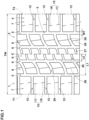
- FIG. 1 is a developed partial view of the tread portion 2 of a tire 1 as an embodiment of the present invention.
- the tire 1 comprises a tread portion 2 having a first tread edge T1 and a second tread edge T2.
- the tread portion 2 is provided with circumferential grooves 3 disposed between the first tread edge T1 and the second tread edge T2 and extending continuously in the tire circumferential direction.
- the tread portion 2 comprises land portions 4 axially divided by the circumferential grooves 3.
- the tread portion 2 is provided with four circumferential grooves 3, and thereby, divided into five land portions 4 as shown in FIG. 1 .
- the tread portion 2 may be divided into four land portions 4 by three circumferential grooves 3.
- the tire 1 is bidirectional, and not specified which side should be outboard when the tire is attached to a vehicle.
- first tread edge T1 is shown as the tread edge on the left side of the tire equator C
- second tread edge T2 is shown as the tread edge on the right side of the tire equator C.
- a half of the tread portion 2 between the first tread edge T1 and the tire equator C has substantially the same configuration as a half of the tread portion 2 between the second tread edge T2 and the tire equator C.
- the tread portion 2 has a pointsymmetrical tread pattern.
- the first tread edge T1 and the second tread edge T2 correspond to the axially outermost edges of the ground contacting patch of the tire 1 when the tire 1 under its normal state is loaded by a normal load and the tread portion 2 is contacted with a flat horizontal surface at a camber angle of 0 degrees.
- the "normal state” means a state of the tire which is mounted on a normal rim and inflated to a normal pressure, but loaded with no tire load.
- the "normal state” means a standard usage state according to the purpose of use of the tire, which is not mounted on the vehicle and loaded with no load.
- the normal rim is a wheel rim officially approved or recommended for the tire by standards organizations, i.e. JATMA (Japan and Asia), T&RA (North America), ETRTO (Europe), TRAA (Australia), STRO (Scandinavia), ALAPA (Latin America), ITTAC (India) and the like which are effective in the area where the tire is manufactured, sold or used.
- the normal pressure is the air pressure officially approved or recommended for the tire by standards organizations, i.e. JATMA (Japan and Asia), T&RA (North America), ETRTO (Europe), TRAA (Australia), STRO (Scandinavia), ALAPA (Latin America), ITTAC (India) and the like which are effective in the area where the tire is manufactured, sold or used.
- the "normal load” is a load specified for the tire by a standard included in a standardization system on which the tire is based, for example, the "maximum load capacity" in JATMA, maximum value listed in “TIRE LOAD LIMITS AT VARIOUS COLD INFLATION PRESSURES" table in TRA, and "LOAD CAPACITY" in ETRTO.
- the "normal load” refers to the maximum load applicable to the tire.
- the circumferential grooves 3 are two shoulder circumferential grooves 5 and two crown circumferential grooves 6.
- the two shoulder circumferential grooves 5 are disposed adjacently to the first tread edge T1 and second tread edge T2, respectively.
- the two crown circumferential grooves 6 are disposed between the shoulder circumferential grooves 5, and one on each side of the tire equator.
- the distance L1 in the tire axial direction from the tire equator C to the groove center line of each of the shoulder circumferential grooves 5 is preferably set in a range from 20% to 30% of the tread width TW.
- the distance L2 in the tire axial direction from the tire equator C to the groove center line of each of the crown circumferential grooves 6 is preferably set in a range from 5% to 15% of the tread width TW.
- the tread width TW is the distance in the tire axial direction between the first tread edge T1 and the second tread edge T2 in the normal state.
- each of the circumferential grooves 3 is a straight groove extending in parallel with the tire circumferential direction.
- all the circumferential grooves 3 or some of them may be non-straight grooves, for example, zigzag or wavy grooves.
- the groove width W1 of each of the circumferential grooves 3 is at least 3 mm.
- the groove width W1 of each of the circumferential grooves 3 is set in a range from 3.0% to 5.0% of the tread width TW.
- the land portions 4 include two shoulder land portions 7.
- the two shoulder land portions 7 include the first tread edge T1 and the second tread edge T2, respectively, and are defined on the axially outside of the respective shoulder circumferential grooves 5.
- the two shoulder land portions 7 have substantially the same configuration.
- the land portions 4 further include two middle land portions 8 and one crown land portion 9.
- the two middle land portions 8 are positioned adjacently to the respective shoulder land portions 7 via the shoulder circumferential grooves 5.
- the two middle land portions 8 are respectively defined between the crown circumferential groove 6 and the respective shoulder circumferential grooves 5.
- the two middle land portions 8 have substantially the same configuration.
- the crown land portion 9 is defined between the two crown circumferential grooves 6 and positioned on the tire equator C.
- FIG. 2 shows the shoulder land portion 7 and the middle land portion 8 which are disposed on the first tread edge T1 side of the tire equator C.
- the shoulder land portion 7 is provided with lateral grooves 12 extending from the shoulder circumferential groove 5 to the first tread edge T1. Thereby, the shoulder land portion 7 is circumferentially divided into shoulder blocks 10 by the shoulder lateral grooves 12.
- FIG. 3 shows three of the shoulder lateral grooves 12 and two of the shoulder blocks 10.
- each of the shoulder blocks 10 is provided with at least one shoulder sipe 15.
- Each shoulder sipe 15 extends from one of the shoulder lateral grooves 12 and ends within the shoulder block 10.
- swipe means an incision having a small width and having two opposite side walls, the two opposite side walls extend substantially parallel to each other, and the width w2 between the two opposite side walls is 2.0 mm or less.
- the expression “substantially parallel” means that the angle between the two opposite side walls is 10 degrees or less.
- the width w2 of the sipe is 0.5 to 1.5 mm, more preferably 0.5 to 1.0 mm.
- the width w2 of the sipe is constant from the opening to the bottom thereof.
- the present invention is not limited to such constant width.
- the width of the sipe may be increased near the open top of the sipe by providing a chamfer for the sipe edge or edges.
- the width of the sipe may be increased near the bottom of the sipe so as to have a flask-shaped cross sectional shape.
- FIG. 4 shows a cross-sectional view taken along line A-A of FIG. 2 .
- the shoulder lateral grooves 12 include a tie-bar-equipped shoulder lateral groove 12 which is, as shown in FIG. 4 , provided with at least one tie bar 20 raising from the groove bottom so as to connect between two of the shoulder blocks 10 adjacent to each other through the tie-bar-equipped shoulder lateral groove 12.
- the tie bars 20 are omitted from the shoulder lateral grooves 12 for the sake of simplicity.
- the tire 1 according to the present invention can exhibit excellent ride comfort performance while maintaining wear resistance of the blocks for the following reasons.
- the shoulder sipes 15 extend from the shoulder lateral grooves 12 and end in the shoulder blocks 10, the rigidity in the tire axial direction of the shoulder blocks 10 can be relaxed, while maintaining the rigidity in the tire circumferential direction of the shoulder blocks 10. Therefore, it is possible to improve the ride comfort performance while maintaining the wear resistance.
- the widths w2 in the tire axial direction of the shoulder blocks 10 are, for example, set in a range from 15% to 25% of the tread width TW.
- the lengths L4 in the tire circumferential direction of the shoulder blocks 10 are smaller than the widths w2 of the shoulder blocks 10.
- the lengths L4 in the tire circumferential direction of the shoulder blocks 10 are set in a range from 60% to 75% of the widths w2 in the tire axial direction of the shoulder blocks 10.
- the ground contacting top surface of each of the shoulder blocks 10 is longer in the tire axial direction than in the tire circumferential direction. Further, it is preferable that the ground contacting top surface has a rectangular shape.
- angles of the shoulder lateral grooves 12 with respect to the tire axial direction are not more than 30 degrees, preferably not more than 20 degrees, more preferably not more than 10 degrees. Most preferably, the shoulder lateral grooves 12 are arranged in parallel with the tire axial direction. Thereby, the wear of the shoulder blocks 10 is further suppressed.
- Each of the shoulder lateral grooves 12 extends from the shoulder circumferential groove 5 to the first tread edge T1 while keeping a constant groove width in order to maintain the wear resistance.
- the groove widths w4 of the shoulder lateral grooves 12 are smaller than the groove widths w3 of the shoulder circumferential grooves 5.
- the groove widths w4 of the shoulder lateral grooves 12 are set in a range from 85% to 95% of the groove widths w3 of the shoulder circumferential grooves 5.
- the above-said at least one shoulder sipe 15 includes a first shoulder sipe 16 and a second shoulder sipe 17.
- each of the shoulder blocks 10 is provided with one first shoulder sipe 16 and one second shoulder sipe 17.
- the first shoulder sipe 16 is connected to one of the shoulder lateral grooves 12 which is positioned on one side of the shoulder block 10 in the tire circumferential direction (lower side in FIG. 3 ), and the second shoulder sipe 17 is connected to one of the shoulder lateral grooves 12 which is positioned on the other side of the shoulder block 10 in the tire circumferential direction (upper side in FIG. 3 ).
- the ride comfort performance is further improved.
- first shoulder sipe 16 and the second shoulder sipe 17 are disposed axially inside the center line 10a of the shoulder block 10 in the tire axial direction (in FIG. 3 , the center line is indicated by alternate long and short dash line).
- edges of the first shoulder sipe 16 and the edges of the second shoulder sipe 17 are completely positioned axially inside the center line 10a.
- the rigidity of the shoulder block 10 is relaxed in its axially inside region, and as a result, the ride comfort performance is further improved.
- the axial distance L3 from the connecting position 16a of the first shoulder sipe 16 with the shoulder lateral groove 12 to the axially inner end of the shoulder lateral groove 12 is preferably set in a range from 30% to 45% of the axial width w2 of the ground contacting top surface of the shoulder block 10.
- the axial distance L3 from the connecting position 17a of the second shoulder sipe 17 with the shoulder lateral groove 12 to the axially inner end of the shoulder lateral groove 12 is preferably set in a range from 30% to 45% of the axial width w2 of the ground contacting top surface of the shoulder block 10.
- the connecting position 17a of the second shoulder sipe 17 with the shoulder lateral groove 12 is displaced in the tire axial direction from the connecting position 16a of the first shoulder sipe 16 with the shoulder lateral groove 12.
- the distance L9 in the tire axial direction between the connecting position 16a and the connecting position 17a is preferably set in a range from 5% to 10% of the axial width w2 of the ground contacting top surface of the shoulder block 10. Thereby, it becomes possible to further improve the wear resistance of the shoulder blocks 10.
- first shoulder sipe 16 and the second shoulder sipe 17 are inclined in the same direction with respect to the tire circumferential direction.
- first shoulder sipe 16 and the second shoulder sipe 17 are inclined at the same angle with respect to the tire circumferential direction.
- the angle ⁇ 1 between the shoulder lateral groove 12 and the shoulder sipe 15 is set in a range from 50 to 80 degrees.
- first shoulder sipe 16 and the second shoulder sipe 17 are arranged such that the first shoulder sipe 16 and the second shoulder sipe 17 are positioned within a narrow zone 19.
- the narrow zone 19 is shown in FIG. 2 by shading with small dots. As shown, the narrow zone 19 extends with a constant width and is inclined in the substantially same direction as the first shoulder sipe 16 and the second shoulder sipe 17 in the top view of the shoulder block 10.
- the constant width of the narrow zone 19 is preferably not more than 10 mm.
- the first shoulder sipe 16 and the second shoulder sipe 17 are arranged so as to extend substantially on a straight line.
- the width of the narrow zone 19 can be the substantially same as the width of the sipes 16 and 17.
- each shoulder sipe 15 (16, 17) ends within the shoulder block 10 without crossing the center line 10b of the shoulder block 10 in the tire circumferential direction (indicated by the alternate long and short dash line in FIG. 2 ).
- the length L5 in the tire circumferential direction of the shoulder sipe 15 is set in a range from 25% to 35% of the length L4 in the tire circumferential direction of the shoulder block 10.
- shoulder sipes 15 serve for improving the wear resistance and the ride comfort performance in a well-balanced manner.
- each of the shoulder blocks 10 is not provided with a groove or a sipe except for the first shoulder sipe 16 and the second shoulder sipe 17.
- the shoulder lateral grooves 12 include the tie-bar-equipped shoulder lateral groove 12 provided with at least one tie bar 20.
- each of the shoulder lateral grooves 12 is formed as the tie-bar-equipped shoulder lateral groove 12 provided a plurality of the tie bars 20 as shown in FIG. 4 . Further, each shoulder sipe 15 (16, 17) is connected to the tie-bar-equipped shoulder lateral groove 12 at the same position in the groove length direction as one of the tie bars 20. This further improves the wear resistance.
- the expression “at the same position as the tie bar 20" means that the shoulder sipe 15 is included in a zone, which extends radially outwardly from the radially outer surface of the tie bar 20 while keeping a constant width equal to that of the radially outer surface, in the cross section of the tie-bar-equipped shoulder lateral groove 12 taken along the length direction of the groove 12.
- the boundary between the radially outer surface and the other surface of the tie bar 20 is lies at the center position of the tie bar 20 in the radial height direction.
- the tie bars 20 are an axially inner tie bar 21, an axially outer tie bar 22, and an intermediate tie bar 23 therebetween.
- the axially inner tie bar 21 is disposed axially inside a center position in the tire axial direction of the tie-bar-equipped shoulder lateral groove 12, wherein the center position is that of the center between the axially inner end at the shoulder circumferential groove 5 and the axially outer end at the first tread edge.
- the axially inner tie bar 21 is disposed at the axially inner end of the tie-bar-equipped shoulder lateral groove 12.
- such inner tie bar 21 serves for suppressing uneven wear occurring near the axially inner end portion of the tie-bar-equipped shoulder lateral groove 12.
- the axially outer tie bar 22 is disposed axially outside the above-mentioned center position of the tie-bar-equipped shoulder lateral groove 12.
- the outer tie bar 22 is disposed at the shoulder lateral groove's axially outer end at the first tread edge.
- the first tread edge T1 is included in this zone.
- the first tread edge T1 is included in the extent of the radially outer surface of the outer tie bar 22 in the length direction of the tie-bar-equipped shoulder lateral groove 12.
- Such outer tie bars 22 serve for suppressing uneven wear occurring near the first tread edge T1.
- the intermediate tie bar 23 is disposed between both ends in the tire axial direction of the shoulder lateral groove 12, and between the axially outer tie bar 22 and the axially inner tie bar 21.
- Such intermediate tie bar 23 can effectively suppress the shoulder lateral groove 12 from opening excessively, and can further improve the wear resistance.
- the shoulder sipe 15 is connected to the shoulder lateral groove 12 at the same position in the groove length direction as the intermediate tie bar 23.
- the shoulder lateral groove 12 in the present embodiment is provided with only the axially inner tie bar 21, axially outer tie bar 22, and intermediate tie bar 23.
- the present invention is not limited to such arrangement.
- the shoulder lateral groove 12 may be provided with only one of these tie bars 20, or only two of these tie bars 20.
- each tie bar 20 is preferably set in a range from 15% to 25% of the axial width w2 of the ground contacting top surface of the shoulder block 10.
- the total length in the tire axial direction of all the tie bars 20 disposed in one shoulder lateral groove 12 is preferably set in a range from 40% to 60% of the axial width w2 of the ground contacting top surface of the shoulder block 10.
- the axial length of the tie bar 20 is measured at the center position in the radial height direction of the tie bar 20.
- the axially inner tie bar 21, axially outer tie bar 22, and intermediate tie bar 23 have the same radial height h1.
- the radial height h1 is set in a range from 25% to 40% of the maximum depth d1 of the shoulder lateral groove 12.
- Each of the two middle land portions 8 is provided with middle lateral grooves 26 as shown in FIG. 2 .
- the middle lateral grooves 26 extend across the entire axial width of the middle land portion 8. Thereby, the middle land portion 8 is circumferentially divided into middle blocks 25.
- the axial width w5 of the ground contacting top surface of the middle block 25 is smaller than the axial width w2 of the ground contacting top surface of the shoulder block 10.
- the axial width w5 is set in a range from 55% to 70% of the axial width w2.
- the middle lateral grooves 26 in this example are inclined with respect to the tire axial direction.
- the angle ⁇ 2 of the middle lateral groove 26 with respect to the tire axial direction is larger than the angle of the shoulder lateral groove 12 with respect to the tire axial direction.
- the angle ⁇ 2 is in a range from 10 to 45 degrees.
- the angle ⁇ 2 of the middle lateral groove 26 increases toward the inside in the tire axial direction.
- the middle lateral groove 26 is curved convexly toward one side in the tire circumferential direction (lower side in FIG. 2 ).
- such middle lateral groove 26 can improve the wet performance in addition to the wear resistance and the ride comfort performance.
- the groove width w6 of the middle lateral groove 26 is larger than the groove width w4 of the shoulder lateral groove 12.
- the groove width w6 of the middle lateral groove 26 is set in a range from 110% to 130% of the groove width w4 of the shoulder lateral groove 12.
- FIG. 5 is a cross-sectional view taken along line B-B of FIG. 2 .
- the middle lateral grooves 26 include a tie-bar-equipped middle lateral groove 26 which is, as shown in FIG. 5 , provided with at least one middle tie bar 30 raising from the groove bottom so as to connect between two of the middle blocks 25 adjacent to each other trough the tie-bar-equipped middle lateral groove 26.
- each of the middle lateral grooves 26 is the tie-bar-equipped middle lateral groove 26 provided with only one middle tie bar 30.
- the middle tie bar 30 serves for increasing the rigidity in the tire circumferential direction of the middle land portion 8 and improving the wear resistance.
- the above-said only one middle tie bar 30 is disposed between both ends in the tire axial direction of the tie-bar-equipped middle lateral groove 26.
- the present invention is not limited to such arrangement.
- a plurality of the middle tie bars 30 may be provided in one middle lateral groove 26.
- the axial length L7 of the middle tie bar 30 is set in a range from 40% to 55% of the axial width w5 of the middle block 25.
- the radial height h2 of the middle tie bar 30 is set in a range from 25% to 40% of the maximum depth d2 of the middle lateral groove 26.
- the middle tie bar 30 is disposed so as to extend across the center position in the tire axial direction of the tie-bar-equipped middle lateral groove 26. Thereby, the wear resistance and the ride comfort performance are improved in a well-balanced manner.
- the middle tie bar 30 is larger than any of the axially inner tie bar 21, outer tie bar 22 and intermediate tie bar 23 provided in the shoulder lateral groove 12.
- the axial length L7 of the middle tie bar 30 is smaller than the total axial length of the axially inner tie bar 21, outer tie bar 22 and intermediate tie bar 23. Thereby, the rigidity distribution of the shoulder land portion 7 and the middle land portion 8 is optimized, and the wear resistance is further improved.
- Each of the middle blocks 25 is provided with at least one middle sipe 28 as shown in FIG. 2 .
- the middle sipe 28 is connected to at least one of the two middle lateral grooves 26 located on both sides in the tire circumferential direction of the middle block 25.
- the middle sipe 28 is connected to the two middle lateral grooves 26 located on both sides in the tire circumferential direction. That is, the middle sipe 28 completely crosses the middle block 25 in the tire circumferential direction.
- each of the both ends in the tire circumferential direction of the middle sipe 28 is connected to a central part of the middle lateral groove 26 when divided into three equal parts in the length direction.
- such middle sipe 28 serves for relaxing the rigidity in the tire axial direction of the middle block 25 and improving the ride comfort performance.
- the middle sipe 28 in this example is inclined with respect to the tire circumferential direction.
- the middle sipe 28 is inclined in the same direction as the shoulder sipes 15.
- the angle ⁇ 3 between the middle sipe 28 and the middle lateral grooves 26 is, for example, set in a range from 75 to 90 degrees.
- such middle sipe 28 serves for improving the wear resistance and the ride comfort performance in a well-balanced manner.
- middle sipe 28 is connected to the middle lateral groove 26 at the same position as the middle tie bar 30 as shown in FIG. 5 .
- the connecting position between the middle lateral groove 26 and the middle sipe 28 is reinforced by the middle tie bar 30, and uneven wear near the connecting position is suppressed.
- each of the middle blocks 25 is not provided with a groove or a sipe except for the middle sipe 28. Thereby, the above-mentioned effect can be further enhanced.
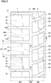
- FIG. 6 is a partial top view of the crown land portion 9.
- the axial width w7 of the crown land portion 9 is, for example, set in a range from 10% to 20% of the tread width Tw.
- the axial width w7 of the crown land portion 9 is smaller than the axial width w2 of the shoulder blocks 10.
- the crown land portion 9 is provided with first crown lateral grooves 36 and second crown lateral grooves 37.
- the first crown lateral grooves 36 extend from the crown circumferential groove 6 on one side in the tire axial direction (left side in FIG. 6 ) of the crown land portion 9 toward the tire equator C, and ends within the crown land portion 9.
- the second crown lateral grooves 37 extend from the crown circumferential groove 6 on the other side in the tire axial direction (right side in FIG. 6 ) of the crown land portion 9 toward the tire equator C, and ends within the crown land portion 9.
- the first crown lateral grooves 36 and the second crown lateral grooves 37 can enhance the wet performance, while maintaining the rigidity of the crown land portion 9.
- the axial length L8 of the first crown lateral groove 36 and the axial length L8 of the second crown lateral groove 37 are preferably set in a range from 45% to 55% of the axial width w7 of the crown land portion 9.
- the first crown lateral grooves 36 are curved convexly toward one side in the tire circumferential direction (upper side in FIG. 6 ).
- the second crown lateral grooves 37 are curved convexly toward the other side in the tire circumferential direction (lower side in FIG. 6 ). Thereby, uneven wear of the crown land portion 9 is further suppressed.
- the middle lateral grooves 26 adjacent to the first crown lateral grooves 36 are curved convexly toward the above-said other side in the tire circumferential direction (lower side in FIG. 1 ).
- the middle lateral grooves 26 adjacent to the second crown lateral grooves 37 are curved convexly toward the above-said one side in the tire circumferential direction (upper side in FIG. 1 ).
- pneumatic tires were experimentally manufactured as working examples Ex.1-Ex.9 according to the present invention.
- a pneumatic tire was experimentally manufactured as a comparative example Ref.
- the shoulder land portions (a) were provided with no sipes, and the shoulder lateral grooves (b) were provided with no tie bars. Otherwise, the comparative example was substantially the same as the working examples.
- the tire sizes were 235/60R17C (rim size 17x6.0J)
- test car 3000cc 4WD car
- test tires mounted on all wheels and inflated to 525 kPa
- the test tires were tested for wear resistance and ride comfort.
- the average of the remaining heights of the shoulder blocks (the average of the remaining groove depths of the shoulder lateral grooves) was obtained.
Landscapes
- Engineering & Computer Science (AREA)
- Mechanical Engineering (AREA)
- Tires In General (AREA)
Description
- The present invention relates to a tire.
- The following
Patent Document 1 discloses a pneumatic tire in which shoulder blocks are provided with shoulder longitudinal sub-grooves extending in the tire circumferential direction. The shoulder longitudinal sub-grooves reduce lateral rigidity in the tire axial direction of the shoulder blocks. Patent Document 1:Japanese Patent Application Publication No. 2015-137015
Related technologies are also known fromEP 2 591 923 A2EP 2 465 706 A2EP 2 610 081 A2JP 2011 084254 A JP 2018 090230 A - when blocks in the tread portion are reduced in rigidity, the amount of deformation of the blocks during running becomes large. For this reason, wear energy acting on the blocks is increased, and consequently, there is a tendency that the wear resistance of the blocks is reduced.
- The present invention was made in view of the above circumstances, and
a primary object of the present invention is to provide a tire capable of exhibiting excellent ride comfort performance while maintaining wear resistance of blocks. - The present invention is set out in the appended claims. A tire comprises
- a tread portion having a first tread edge, and provided with a shoulder circumferential groove disposed adjacently to the first tread edge and extending continuously in the tire circumferential direction, so as to define a shoulder land portion between the shoulder circumferential groove and the first tread edge,
wherein - the shoulder land portion is provided with shoulder lateral grooves extending from the shoulder circumferential groove to the first tread edge, so as to circumferentially divide the shoulder land portion into shoulder blocks,
- each of the shoulder blocks is provided with one or more shoulder sipes each extending from one of the shoulder lateral grooves and ending within the shoulder block, and
- the shoulder lateral grooves include a tie-bar-equipped shoulder lateral groove provided with at least one tie bar rising from the groove bottom so as to connect between two of the shoulder blocks adjacent to the tie-bar-equipped shoulder lateral groove.
- In the present invention, therefore, the tire can exhibit excellent ride comfort performance, while maintaining wear resistance of the block.
-
-
FIG. 1 is a developed partial view of the tread portion of a tire as an embodiment of the present invention. -
FIG. 2 is an enlarged view showing a shoulder land portion and a middle land portion shown inFIG. 1 . -
FIG.3 is an enlarged view showing shoulder blocks and shoulder lateral grooves shown inFIG. 2 . -
FIG. 4 is a cross-sectional view taken along line A-A ofFIG. 2 . -
FIG. 5 is a cross-sectional view taken along line B-B ofFIG. 2 . -
FIG. 6 is an enlarged view showing a crown land portion shown inFIG. 1 . -
FIG. 7 is a developed partial view of the tread portion of a tire as a comparative example. - The present invention is suitably applied to pneumatic tires for passenger cars, but the present invention may be applied to pneumatic tires for heavy duty vehicles such as trucks and buses, as well as non-pneumatic tires so called airless tire.
- Taking a pneumatic tire for a passenger car as an example, an embodiment of the present invention will be described in detail in conjunction with accompanying drawings.
-
FIG. 1 is a developed partial view of thetread portion 2 of atire 1 as an embodiment of the present invention. - The
tire 1 comprises atread portion 2 having a first tread edge T1 and a second tread edge T2. - The
tread portion 2 is provided withcircumferential grooves 3 disposed between the first tread edge T1 and the second tread edge T2 and extending continuously in the tire circumferential direction. - The
tread portion 2 comprisesland portions 4 axially divided by thecircumferential grooves 3. - In the present embodiment, the
tread portion 2 is provided with fourcircumferential grooves 3, and thereby, divided into fiveland portions 4 as shown inFIG. 1 . - The present invention is however, not limited to such tread pattern. For example, the
tread portion 2 may be divided into fourland portions 4 by threecircumferential grooves 3. - In the present embodiment, the
tire 1 is bidirectional, and not specified which side should be outboard when the tire is attached to a vehicle. - For convenience, in each of the figures herein, the first tread edge T1 is shown as the tread edge on the left side of the tire equator C, and the second tread edge T2 is shown as the tread edge on the right side of the tire equator C.
- It is preferable that a half of the
tread portion 2 between the first tread edge T1 and the tire equator C has substantially the same configuration as a half of thetread portion 2 between the second tread edge T2 and the tire equator C. - It is preferable that the
tread portion 2 has a pointsymmetrical tread pattern. - The first tread edge T1 and the second tread edge T2 correspond to the axially outermost edges of the ground contacting patch of the
tire 1 when thetire 1 under its normal state is loaded by a normal load and thetread portion 2 is contacted with a flat horizontal surface at a camber angle of 0 degrees. - In the case of a pneumatic tire for which various standards have been established, the "normal state" means a state of the tire which is mounted on a normal rim and inflated to a normal pressure, but loaded with no tire load.
- In the case of tires for which no standard is established such as airless tires, the "normal state" means a standard usage state according to the purpose of use of the tire, which is not mounted on the vehicle and loaded with no load.
- In the present invention, unless otherwise noted, dimensions, positions and the like of the tire refer to those under the normal state.
- The normal rim is a wheel rim officially approved or recommended for the tire by standards organizations, i.e. JATMA (Japan and Asia), T&RA (North America), ETRTO (Europe), TRAA (Australia), STRO (Scandinavia), ALAPA (Latin America), ITTAC (India) and the like which are effective in the area where the tire is manufactured, sold or used.
- The normal pressure is the air pressure officially approved or recommended for the tire by standards organizations, i.e. JATMA (Japan and Asia), T&RA (North America), ETRTO (Europe), TRAA (Australia), STRO (Scandinavia), ALAPA (Latin America), ITTAC (India) and the like which are effective in the area where the tire is manufactured, sold or used.
- In the case of a pneumatic tire for which various standards have been established, the "normal load" is a load specified for the tire by a standard included in a standardization system on which the tire is based, for example, the "maximum load capacity" in JATMA, maximum value listed in "TIRE LOAD LIMITS AT VARIOUS COLD INFLATION PRESSURES" table in TRA, and "LOAD CAPACITY" in ETRTO.
- In the case of tires for which no standard is established, the "normal load" refers to the maximum load applicable to the tire.
- In the present embodiment, the
circumferential grooves 3 are two shouldercircumferential grooves 5 and two crowncircumferential grooves 6. - The two shoulder
circumferential grooves 5 are disposed adjacently to the first tread edge T1 and second tread edge T2, respectively. - The two crown
circumferential grooves 6 are disposed between the shouldercircumferential grooves 5, and one on each side of the tire equator. - The distance L1 in the tire axial direction from the tire equator C to the groove center line of each of the shoulder
circumferential grooves 5 is preferably set in a range from 20% to 30% of the tread width TW. - The distance L2 in the tire axial direction from the tire equator C to the groove center line of each of the crown
circumferential grooves 6 is preferably set in a range from 5% to 15% of the tread width TW. - The tread width TW is the distance in the tire axial direction between the first tread edge T1 and the second tread edge T2 in the normal state.
- In the present embodiment, each of the
circumferential grooves 3 is a straight groove extending in parallel with the tire circumferential direction. However, all thecircumferential grooves 3 or some of them may be non-straight grooves, for example, zigzag or wavy grooves. - It is preferable that the groove width W1 of each of the
circumferential grooves 3 is at least 3 mm. - Further, it is preferable that the groove width W1 of each of the
circumferential grooves 3 is set in a range from 3.0% to 5.0% of the tread width TW. - The
land portions 4 include twoshoulder land portions 7. The twoshoulder land portions 7 include the first tread edge T1 and the second tread edge T2, respectively, and are defined on the axially outside of the respective shouldercircumferential grooves 5. - The two
shoulder land portions 7 have substantially the same configuration. - The
land portions 4 further include twomiddle land portions 8 and onecrown land portion 9. - The two
middle land portions 8 are positioned adjacently to the respectiveshoulder land portions 7 via the shouldercircumferential grooves 5. - The two
middle land portions 8 are respectively defined between the crowncircumferential groove 6 and the respective shouldercircumferential grooves 5. - The two
middle land portions 8 have substantially the same configuration. - The
crown land portion 9 is defined between the twocrown circumferential grooves 6 and positioned on the tire equator C. -
FIG. 2 shows theshoulder land portion 7 and themiddle land portion 8 which are disposed on the first tread edge T1 side of the tire equator C. - As shown in
FIG. 2 , theshoulder land portion 7 is provided withlateral grooves 12 extending from the shouldercircumferential groove 5 to the first tread edge T1. Thereby, theshoulder land portion 7 is circumferentially divided intoshoulder blocks 10 by theshoulder lateral grooves 12. -
FIG. 3 shows three of theshoulder lateral grooves 12 and two of the shoulder blocks 10. - As shown, each of the shoulder blocks 10 is provided with at least one
shoulder sipe 15. - Each
shoulder sipe 15 extends from one of theshoulder lateral grooves 12 and ends within theshoulder block 10. - The term "sipe" means an incision having a small width and having two opposite side walls, the two opposite side walls extend substantially parallel to each other, and the width w2 between the two opposite side walls is 2.0 mm or less.
- Further, the expression "substantially parallel" means that the angle between the two opposite side walls is 10 degrees or less. Preferably, the width w2 of the sipe is 0.5 to 1.5 mm, more preferably 0.5 to 1.0 mm.
- In the present embodiment, the width w2 of the sipe is constant from the opening to the bottom thereof.
- However, the present invention is not limited to such constant width. For example, the width of the sipe may be increased near the open top of the sipe by providing a chamfer for the sipe edge or edges.
- Further, the width of the sipe may be increased near the bottom of the sipe so as to have a flask-shaped cross sectional shape.
-
FIG. 4 shows a cross-sectional view taken along line A-A ofFIG. 2 . - The
shoulder lateral grooves 12 include a tie-bar-equipped shoulderlateral groove 12 which is, as shown inFIG. 4 , provided with at least onetie bar 20 raising from the groove bottom so as to connect between two of the shoulder blocks 10 adjacent to each other through the tie-bar-equipped shoulderlateral groove 12. InFIGS. 1 to 3 , the tie bars 20 are omitted from theshoulder lateral grooves 12 for the sake of simplicity. - By adopting the above configuration, the
tire 1 according to the present invention can exhibit excellent ride comfort performance while maintaining wear resistance of the blocks for the following reasons. - According to the present invention, since the
shoulder sipes 15 extend from theshoulder lateral grooves 12 and end in the shoulder blocks 10, the rigidity in the tire axial direction of the shoulder blocks 10 can be relaxed, while maintaining the rigidity in the tire circumferential direction of the shoulder blocks 10. Therefore, it is possible to improve the ride comfort performance while maintaining the wear resistance. - on the other hand, by providing the tie bars 20 in the
shoulder lateral grooves 12, the deformation of theshoulder land portions 7 is appropriately suppressed, and the wear resistance can be further maintained. - In the present invention, therefore, excellent ride comfort performance can be exhibited while maintaining the wear resistance of the blocks.
- Hereinafter, the present embodiment will be described in more detail.
- Each configuration described below shows a specific example for the present embodiment.
- Therefore, even if the tire does not have the configuration described below, the tire will exert the above-mentioned effects of the present invention.
- Further, even if any one of the configurations described below is independently applied to the tire having the above-mentioned configurations of the present invention, improvement in performance according to the applied configuration can be expected.
- Further, when some of the configurations described below are applied in combination, to the tire having the above-mentioned configurations of the present invention, multiple effect according to the applied configurations on the improvement in performance can be expected.
- As shown in
FIG. 2 , the widths w2 in the tire axial direction of the shoulder blocks 10 are, for example, set in a range from 15% to 25% of the tread width TW. - Further, the lengths L4 in the tire circumferential direction of the shoulder blocks 10 are smaller than the widths w2 of the shoulder blocks 10.
- specifically, the lengths L4 in the tire circumferential direction of the shoulder blocks 10 are set in a range from 60% to 75% of the widths w2 in the tire axial direction of the shoulder blocks 10. As a result, the ground contacting top surface of each of the shoulder blocks 10 is longer in the tire axial direction than in the tire circumferential direction. Further, it is preferable that the ground contacting top surface has a rectangular shape.
- The angles of the
shoulder lateral grooves 12 with respect to the tire axial direction are not more than 30 degrees, preferably not more than 20 degrees, more preferably not more than 10 degrees. Most preferably, theshoulder lateral grooves 12 are arranged in parallel with the tire axial direction. Thereby, the wear of the shoulder blocks 10 is further suppressed. - Each of the
shoulder lateral grooves 12 extends from the shouldercircumferential groove 5 to the first tread edge T1 while keeping a constant groove width in order to maintain the wear resistance. - Further, it is preferable that the groove widths w4 of the
shoulder lateral grooves 12 are smaller than the groove widths w3 of the shouldercircumferential grooves 5. - specifically, the groove widths w4 of the
shoulder lateral grooves 12 are set in a range from 85% to 95% of the groove widths w3 of the shouldercircumferential grooves 5. - In the present embodiment, as shown in
FIG. 3 , the above-said at least oneshoulder sipe 15 includes afirst shoulder sipe 16 and asecond shoulder sipe 17. - Preferably, each of the shoulder blocks 10 is provided with one
first shoulder sipe 16 and onesecond shoulder sipe 17. - In each of the shoulder blocks 10, the
first shoulder sipe 16 is connected to one of theshoulder lateral grooves 12 which is positioned on one side of theshoulder block 10 in the tire circumferential direction (lower side inFIG. 3 ), and thesecond shoulder sipe 17 is connected to one of theshoulder lateral grooves 12 which is positioned on the other side of theshoulder block 10 in the tire circumferential direction (upper side inFIG. 3 ). Thereby, the ride comfort performance is further improved. - It is preferable that the
first shoulder sipe 16 and thesecond shoulder sipe 17 are disposed axially inside thecenter line 10a of theshoulder block 10 in the tire axial direction (inFIG. 3 , the center line is indicated by alternate long and short dash line). - More specifically, the edges of the
first shoulder sipe 16 and the edges of thesecond shoulder sipe 17 are completely positioned axially inside thecenter line 10a. - Therefore, the rigidity of the
shoulder block 10 is relaxed in its axially inside region, and as a result, the ride comfort performance is further improved. - on the other hand, if the
first shoulder sipe 16 and thesecond shoulder sipe 17 are disposed excessively close to the shouldercircumferential groove 5, there is a possibility that uneven wear occurs on theshoulder block 10. - Therefore, the axial distance L3 from the connecting
position 16a of thefirst shoulder sipe 16 with theshoulder lateral groove 12 to the axially inner end of theshoulder lateral groove 12 is preferably set in a range from 30% to 45% of the axial width w2 of the ground contacting top surface of theshoulder block 10. - And the axial distance L3 from the connecting
position 17a of thesecond shoulder sipe 17 with theshoulder lateral groove 12 to the axially inner end of theshoulder lateral groove 12 is preferably set in a range from 30% to 45% of the axial width w2 of the ground contacting top surface of theshoulder block 10. - It is preferable that the connecting
position 17a of thesecond shoulder sipe 17 with theshoulder lateral groove 12 is displaced in the tire axial direction from the connectingposition 16a of thefirst shoulder sipe 16 with theshoulder lateral groove 12. - The distance L9 in the tire axial direction between the connecting
position 16a and the connectingposition 17a is preferably set in a range from 5% to 10% of the axial width w2 of the ground contacting top surface of theshoulder block 10. Thereby, it becomes possible to further improve the wear resistance of the shoulder blocks 10. - In order to further improve the wear resistance of the shoulder blocks 10, it is preferred that the
first shoulder sipe 16 and thesecond shoulder sipe 17 are inclined in the same direction with respect to the tire circumferential direction. - In the present embodiment, the
first shoulder sipe 16 and thesecond shoulder sipe 17 are inclined at the same angle with respect to the tire circumferential direction. - Preferably, the angle θ1 between the
shoulder lateral groove 12 and theshoulder sipe 15 is set in a range from 50 to 80 degrees. - In each of the shoulder blocks 10, the
first shoulder sipe 16 and thesecond shoulder sipe 17 are arranged such that thefirst shoulder sipe 16 and thesecond shoulder sipe 17 are positioned within anarrow zone 19. - The
narrow zone 19 is shown inFIG. 2 by shading with small dots. As shown, thenarrow zone 19 extends with a constant width and is inclined in the substantially same direction as thefirst shoulder sipe 16 and thesecond shoulder sipe 17 in the top view of theshoulder block 10. The constant width of thenarrow zone 19 is preferably not more than 10 mm. - In this example, in order to further improve the ride comfort performance, the
first shoulder sipe 16 and thesecond shoulder sipe 17 are arranged so as to extend substantially on a straight line. In this case, the width of thenarrow zone 19 can be the substantially same as the width of thesipes - It is preferable that each shoulder sipe 15 (16, 17) ends within the
shoulder block 10 without crossing thecenter line 10b of theshoulder block 10 in the tire circumferential direction (indicated by the alternate long and short dash line inFIG. 2 ). - It is preferable that the length L5 in the tire circumferential direction of the
shoulder sipe 15 is set in a range from 25% to 35% of the length L4 in the tire circumferential direction of theshoulder block 10. -
such shoulder sipes 15 serve for improving the wear resistance and the ride comfort performance in a well-balanced manner. - In the present embodiment, the ground contacting top surface of each of the shoulder blocks 10 is not provided with a groove or a sipe except for the
first shoulder sipe 16 and thesecond shoulder sipe 17. Thereby, the above described effects are surely exhibited. - The
shoulder lateral grooves 12 include the tie-bar-equipped shoulderlateral groove 12 provided with at least onetie bar 20. - In the embodiment, each of the
shoulder lateral grooves 12 is formed as the tie-bar-equipped shoulderlateral groove 12 provided a plurality of the tie bars 20 as shown inFIG. 4 . Further, each shoulder sipe 15 (16, 17) is connected to the tie-bar-equipped shoulderlateral groove 12 at the same position in the groove length direction as one of the tie bars 20. This further improves the wear resistance. - The expression "at the same position as the
tie bar 20" means that theshoulder sipe 15 is included in a zone, which extends radially outwardly from the radially outer surface of thetie bar 20 while keeping a constant width equal to that of the radially outer surface, in the cross section of the tie-bar-equipped shoulderlateral groove 12 taken along the length direction of thegroove 12. The boundary between the radially outer surface and the other surface of thetie bar 20 is lies at the center position of thetie bar 20 in the radial height direction. - In this embodiment, as shown in
FIG. 4 , the tie bars 20 are an axiallyinner tie bar 21, an axiallyouter tie bar 22, and anintermediate tie bar 23 therebetween. - The axially
inner tie bar 21 is disposed axially inside a center position in the tire axial direction of the tie-bar-equipped shoulderlateral groove 12, wherein the center position is that of the center between the axially inner end at the shouldercircumferential groove 5 and the axially outer end at the first tread edge. - Preferably, the axially
inner tie bar 21 is disposed at the axially inner end of the tie-bar-equipped shoulderlateral groove 12. suchinner tie bar 21 serves for suppressing uneven wear occurring near the axially inner end portion of the tie-bar-equipped shoulderlateral groove 12. - The axially
outer tie bar 22 is disposed axially outside the above-mentioned center position of the tie-bar-equipped shoulderlateral groove 12. - Preferably, the
outer tie bar 22 is disposed at the shoulder lateral groove's axially outer end at the first tread edge. specifically, in a cross section of the tie-bar-equipped shoulderlateral groove 12 taken along the length direction of the tie-bar-equipped shoulderlateral groove 12, when a zone which extends radially outwardly from the radially outer surface of theouter tie bar 22 while keeping a constant width equal to the width of the radially outer surface, is set, the first tread edge T1 is included in this zone. - In other words, the first tread edge T1 is included in the extent of the radially outer surface of the
outer tie bar 22 in the length direction of the tie-bar-equipped shoulderlateral groove 12. - such outer tie bars 22 serve for suppressing uneven wear occurring near the first tread edge T1.
- The
intermediate tie bar 23 is disposed between both ends in the tire axial direction of theshoulder lateral groove 12, and between the axiallyouter tie bar 22 and the axiallyinner tie bar 21. - such
intermediate tie bar 23 can effectively suppress theshoulder lateral groove 12 from opening excessively, and can further improve the wear resistance. - In the present embodiment, the
shoulder sipe 15 is connected to theshoulder lateral groove 12 at the same position in the groove length direction as theintermediate tie bar 23. - The
shoulder lateral groove 12 in the present embodiment is provided with only the axiallyinner tie bar 21, axiallyouter tie bar 22, andintermediate tie bar 23. - But, the present invention is not limited to such arrangement. For example, the
shoulder lateral groove 12 may be provided with only one of these tie bars 20, or only two of these tie bars 20. - The axial length L6 of each
tie bar 20 is preferably set in a range from 15% to 25% of the axial width w2 of the ground contacting top surface of theshoulder block 10. - The total length in the tire axial direction of all the tie bars 20 disposed in one
shoulder lateral groove 12 is preferably set in a range from 40% to 60% of the axial width w2 of the ground contacting top surface of theshoulder block 10. - Here, the axial length of the
tie bar 20 is measured at the center position in the radial height direction of thetie bar 20. As a result, the wear resistance and the ride comfort performance are improved in a well-balanced manner. - In the present embodiment, the axially
inner tie bar 21, axiallyouter tie bar 22, andintermediate tie bar 23 have the same radial height h1. - Preferably, the radial height h1 is set in a range from 25% to 40% of the maximum depth d1 of the
shoulder lateral groove 12. - Each of the two
middle land portions 8 is provided with middlelateral grooves 26 as shown inFIG. 2 . - The middle
lateral grooves 26 extend across the entire axial width of themiddle land portion 8. Thereby, themiddle land portion 8 is circumferentially divided into middle blocks 25. - It is preferable that the axial width w5 of the ground contacting top surface of the
middle block 25 is smaller than the axial width w2 of the ground contacting top surface of theshoulder block 10. - It is preferable that the axial width w5 is set in a range from 55% to 70% of the axial width w2.
- Thereby, the progress of wear of the shoulder blocks 10 and the middle blocks 25 becomes uniform, and uneven wear of the shoulder blocks 10 and
middle blocks 25 is suppressed. - The middle
lateral grooves 26 in this example are inclined with respect to the tire axial direction. - The angle θ2 of the middle
lateral groove 26 with respect to the tire axial direction is larger than the angle of theshoulder lateral groove 12 with respect to the tire axial direction. - For example, the angle θ2 is in a range from 10 to 45 degrees. In the present embodiment, the angle θ2 of the middle
lateral groove 26 increases toward the inside in the tire axial direction. Thereby, the middlelateral groove 26 is curved convexly toward one side in the tire circumferential direction (lower side inFIG. 2 ). - such middle
lateral groove 26 can improve the wet performance in addition to the wear resistance and the ride comfort performance. - In the present embodiment, the groove width w6 of the middle
lateral groove 26 is larger than the groove width w4 of theshoulder lateral groove 12. For example, the groove width w6 of the middlelateral groove 26 is set in a range from 110% to 130% of the groove width w4 of theshoulder lateral groove 12. Thereby, the progress of wear of theshoulder land portion 7 and themiddle land portion 8 becomes uniform, and uneven wear of theshoulder land portion 7 and themiddle land portion 8 is suppressed. -
FIG. 5 is a cross-sectional view taken along line B-B ofFIG. 2 . - The middle
lateral grooves 26 include a tie-bar-equipped middlelateral groove 26 which is, as shown inFIG. 5 , provided with at least onemiddle tie bar 30 raising from the groove bottom so as to connect between two of the middle blocks 25 adjacent to each other trough the tie-bar-equipped middlelateral groove 26. - In the present embodiment, each of the middle
lateral grooves 26 is the tie-bar-equipped middlelateral groove 26 provided with only onemiddle tie bar 30. - The
middle tie bar 30 serves for increasing the rigidity in the tire circumferential direction of themiddle land portion 8 and improving the wear resistance. - In the present embodiment, the above-said only one
middle tie bar 30 is disposed between both ends in the tire axial direction of the tie-bar-equipped middlelateral groove 26. However, the present invention is not limited to such arrangement. For example, a plurality of the middle tie bars 30 may be provided in onemiddle lateral groove 26. - For example, the axial length L7 of the
middle tie bar 30 is set in a range from 40% to 55% of the axial width w5 of themiddle block 25. - The radial height h2 of the
middle tie bar 30 is set in a range from 25% to 40% of the maximum depth d2 of the middlelateral groove 26. - In the present embodiment, the
middle tie bar 30 is disposed so as to extend across the center position in the tire axial direction of the tie-bar-equipped middlelateral groove 26. Thereby, the wear resistance and the ride comfort performance are improved in a well-balanced manner. - It is preferable that, when the axial lengths of the tie bars are compared, the
middle tie bar 30 is larger than any of the axiallyinner tie bar 21,outer tie bar 22 andintermediate tie bar 23 provided in theshoulder lateral groove 12. - On the other hand, it is preferable that the axial length L7 of the
middle tie bar 30 is smaller than the total axial length of the axiallyinner tie bar 21,outer tie bar 22 andintermediate tie bar 23. Thereby, the rigidity distribution of theshoulder land portion 7 and themiddle land portion 8 is optimized, and the wear resistance is further improved. - Each of the middle blocks 25 is provided with at least one
middle sipe 28 as shown inFIG. 2 . - The
middle sipe 28 is connected to at least one of the two middlelateral grooves 26 located on both sides in the tire circumferential direction of themiddle block 25. - In the present embodiment, the
middle sipe 28 is connected to the two middlelateral grooves 26 located on both sides in the tire circumferential direction. That is, themiddle sipe 28 completely crosses themiddle block 25 in the tire circumferential direction. - Further, it is preferable that each of the both ends in the tire circumferential direction of the
middle sipe 28 is connected to a central part of the middlelateral groove 26 when divided into three equal parts in the length direction. - such
middle sipe 28 serves for relaxing the rigidity in the tire axial direction of themiddle block 25 and improving the ride comfort performance. - The
middle sipe 28 in this example is inclined with respect to the tire circumferential direction. - It is preferable that the
middle sipe 28 is inclined in the same direction as theshoulder sipes 15. - The angle θ3 between the
middle sipe 28 and the middlelateral grooves 26 is, for example, set in a range from 75 to 90 degrees. suchmiddle sipe 28 serves for improving the wear resistance and the ride comfort performance in a well-balanced manner. - It is preferable that the
middle sipe 28 is connected to the middlelateral groove 26 at the same position as themiddle tie bar 30 as shown inFIG. 5 . - Thereby, the connecting position between the middle
lateral groove 26 and themiddle sipe 28 is reinforced by themiddle tie bar 30, and uneven wear near the connecting position is suppressed. - In the present embodiment, as shown in
FIG. 2 , each of the middle blocks 25 is not provided with a groove or a sipe except for themiddle sipe 28. Thereby, the above-mentioned effect can be further enhanced. -
FIG. 6 is a partial top view of thecrown land portion 9. As shown inFIG. 6 , the axial width w7 of thecrown land portion 9 is, for example, set in a range from 10% to 20% of the tread width Tw. - It is preferable that the axial width w7 of the
crown land portion 9 is smaller than the axial width w2 of the shoulder blocks 10. - The
crown land portion 9 is provided with firstcrown lateral grooves 36 and secondcrown lateral grooves 37. - The first
crown lateral grooves 36 extend from the crowncircumferential groove 6 on one side in the tire axial direction (left side inFIG. 6 ) of thecrown land portion 9 toward the tire equator C, and ends within thecrown land portion 9. - The second
crown lateral grooves 37 extend from the crowncircumferential groove 6 on the other side in the tire axial direction (right side inFIG. 6 ) of thecrown land portion 9 toward the tire equator C, and ends within thecrown land portion 9. - The first
crown lateral grooves 36 and the secondcrown lateral grooves 37 can enhance the wet performance, while maintaining the rigidity of thecrown land portion 9. - In order to improve the wear resistance and the ride comfort in a well-balanced manner, the axial length L8 of the first
crown lateral groove 36 and the axial length L8 of the secondcrown lateral groove 37 are preferably set in a range from 45% to 55% of the axial width w7 of thecrown land portion 9. - The first
crown lateral grooves 36 are curved convexly toward one side in the tire circumferential direction (upper side inFIG. 6 ). The secondcrown lateral grooves 37 are curved convexly toward the other side in the tire circumferential direction (lower side inFIG. 6 ). Thereby, uneven wear of thecrown land portion 9 is further suppressed. - The middle
lateral grooves 26 adjacent to the firstcrown lateral grooves 36 are curved convexly toward the above-said other side in the tire circumferential direction (lower side inFIG. 1 ). - The middle
lateral grooves 26 adjacent to the secondcrown lateral grooves 37 are curved convexly toward the above-said one side in the tire circumferential direction (upper side inFIG. 1 ). - By arranging the lateral grooves in such way, the progress of wear in each land portion becomes uniform, and uneven wear in each land portion is suppressed.
- while detailed description has been made of a preferable embodiment of the present invention, the present invention can be embodied in various forms without being limited to the illustrated embodiment.
- Based on the tread pattern shown in
FIG. 1 , pneumatic tires were experimentally manufactured as working examples Ex.1-Ex.9 according to the present invention. - Further, based on the tread pattern shown in
FIG. 7 , a pneumatic tire was experimentally manufactured as a comparative example Ref. In the comparative example, as shown inFIG. 7 , the shoulder land portions (a) were provided with no sipes, and the shoulder lateral grooves (b) were provided with no tie bars. Otherwise, the comparative example was substantially the same as the working examples. - Specifications of these test tires are shown in Table 1.
- The tire sizes were 235/60R17C (rim size 17x6.0J)
- Using a test car (3000cc 4WD car) with the same test tires mounted on all wheels and inflated to 525 kPa, the test tires were tested for wear resistance and ride comfort.
- After running for 30,000 km on general roads and highways with the above test vehicle, the average of the remaining heights of the shoulder blocks (the average of the remaining groove depths of the shoulder lateral grooves) was obtained.
- The results are indicated in Table 1 by an index based on the comparative example being 100, wherein the larger the value, the better the wear resistance of the shoulder blocks.
- when running on general roads and highways with the above test vehicle, the ride comfort was evaluated by the driver. The results are indicated in Table 1 by an index based on the comparative example being 100, wherein the larger the value, the better the ride comfort.
Table 1 tire Ref. Ex.1 Ex.2 Ex.3 Ex. 4 tread pattern Fig.7 Fig.1 Fig.1 Fig.1 Fig.1 (P)resence or (A)bsence of shoulder sipe A P P P P (P)resence or (A)bsence of tie bar in shoulder lateral groove A P P P P angle θ1 between shoulder sipe and shoulder lateral groove (deg.) -- 70 50 60 75 shoulder sipe length L5/shoulder block length L4 (%) -- 30 30 30 30 wear resistance 100 104 102 103 104 ride comfort 100 110 110 110 109 tire Ex.5 Ex. 6 Ex.7 Ex.8 Ex.9 tread pattern Fig.1 Fig.1 Fig.1 Fig.1 Fig.1 (P)resence or (A)bsence of shoulder sipe P P P P P (P)resence or (A)bsence of tie bar in shoulder lateral groove P P P P P angle θ1 between shoulder sipe and shoulder lateral groove (deg.) 80 70 70 70 70 shoulder sipe length L5/shoulder block length L4 (%) 30 20 25 35 40 wear resistance 105 105 104 102 101 ride comfort 108 105 108 111 112 - From the test results, it was confirmed that the tires according to the present invention exhibited excellent ride comfort performance while maintaining the wear resistance of the blocks.
-
- 2
- tread portion
- 5
- shoulder circumferential groove
- 7
- shoulder land portion
- 10
- shoulder block
- 12
- shoulder lateral groove
- 15
- shoulder sipe
- 20
- tie bar
- T1
- first tread edge
Claims (13)
- A tire (1) comprising:a tread portion (2) having a first tread edge (T1), and provided with a shoulder circumferential groove (5) disposed adjacently to the first tread edge (T1) and extending continuously in the tire circumferential direction, so as to define a shoulder land portion (7) between the shoulder circumferential groove (5) and the first tread edge (T1), whereinthe shoulder land portion (7) is provided with shoulder lateral grooves (12) extending from the shoulder circumferential groove (5) to the first tread edge (T1), so as to circumferentially divide the shoulder land portion (7) into shoulder blocks (10),each of the shoulder blocks (10) is provided with a shoulder sipe (15) which extends from one of the shoulder lateral grooves (12) and ends within the shoulder block (10), andthe shoulder lateral grooves (12) include a tie-bar-equipped shoulder lateral groove (12) which is provided with at least one tie bar (20) raising from the groove bottom so as to connect between two of the shoulder blocks (10) adjacent to the tie-bar-equipped shoulder lateral groove (12),
characterized in thatsaid at least one tie bar (20) includes an axially outer tie bar (22) positioned axially outside the center position in the tire axial direction of the tie-bar-equipped shoulder lateral groove (12). - The tire according to claim 1, wherein
said at least one tie bar (20) includes an axially inner tie bar (21) positioned axially inside a center position in the tire axial direction of the tie-bar-equipped shoulder lateral groove (12). - The tire according to claim 1 or 2, wherein
said at least one tie bar (20) includes an intermediate tie bar (23) positioned between both ends in the tire axial direction of the tie-bar-equipped shoulder lateral groove (12). - The tire according to claim 1, 2, or 3, whereinsaid at least one tie bar (20) of the tie-bar-equipped shoulder lateral groove (12) is a plurality of the tie bars, andthe shoulder sipe (15) which extends from the tie-bar-equipped shoulder lateral groove (12) is connected to the tie-bar-equipped shoulder lateral groove (12) at the same position as one of the tie bars (20).
- The tire according to any one of claims 1 to 4, whereinsaid at least one tie bar of the tie-bar-equipped shoulder lateral groove (12) includes an intermediate tie bar (23) positioned between both ends in the tire axial direction of the tie-bar-equipped shoulder lateral groove (12), andthe shoulder sipe (15) which extends from the tie-bar-equipped shoulder lateral groove (12) is connected to the tie-bar-equipped shoulder lateral groove (12) at the same position as the intermediate tie bar (23).
- The tire according to any one of claims 1 to 5, wherein
said shoulder sipe (15) of each shoulder block (10) includesa first shoulder sipe (16) connected to one of the shoulder lateral grooves (12) which is located on one side in the tire circumferential direction of the shoulder block (10), anda second shoulder sipe (17) connected to one of the shoulder lateral grooves (12) which is located on the other side in the tire circumferential direction of the shoulder block (10). - The tire according to claim 6, wherein
the first shoulder sipe (16) and the second shoulder sipe (17) are inclined in the same direction with respect to the tire circumferential direction. - The tire according to claim 6 or 7, wherein
the connecting position (17a) between the second shoulder sipe (17) and said one of the shoulder lateral grooves (12)is displaced in the tire axial direction fromthe connecting position (16a) between the first shoulder sipe (16) and said one of the shoulder lateral grooves (12). - The tire according to any one of claims 1 to 8, wherein
in each of the shoulder blocks (10) provided with the shoulder sipe (15), the length (L5) in the tire circumferential direction of the shoulder sipe (15) is 25% to 35% of the length (L4) in the tire circumferential direction of the shoulder block (10). - The tire according to any one of claims 1 to 9, wherein
the angle (θ1) between the shoulder sipe (15) and the shoulder lateral groove (12) from which the shoulder sipe (15) extends, is in a range from 50 to 80 degrees. - The tire according to any one of claims 1 to 10, whereinthe tread portion (2) comprises a middle land portion (8) adjacent to the shoulder land portion (7) via the shoulder circumferential groove (5),the middle land portion (8) is provided with a plurality of middle lateral grooves (26) extending across the entire axial width of the middle land portion (8) so as to circumferentially divide the middle land portion into middle blocks (25), andthe middle lateral grooves (26) include a tie-bar-equipped middle lateral groove (26) provided with at least one middle tie bar (30) raising from the groove bottom so as to connect between two of the middle blocks (25) adjacent to the tie-bar-equipped middle lateral groove (26).
- The tire according to claim 11, whereineach of the middle blocks (25) is provided with a middle sipe (28) connected to one of the middle lateral grooves (26), andwhen the middle lateral groove (26) to which the middle sipe (28) is connected is the tie-bar-equipped middle lateral groove (26),the middle sipe (28) is connected at the same position as the only one middle tie bar (30) or one of the middle tie bars (30).
- The tire according to claim 12, wherein
said at least one middle sipe (28) completely crosses the middle block (25) in the tire circumferential direction.
Applications Claiming Priority (1)
| Application Number | Priority Date | Filing Date | Title |
|---|---|---|---|
| JP2021170444A JP7726004B2 (en) | 2021-10-18 | 2021-10-18 | tire |
Publications (2)
| Publication Number | Publication Date |
|---|---|
| EP4166356A1 EP4166356A1 (en) | 2023-04-19 |
| EP4166356B1 true EP4166356B1 (en) | 2025-01-01 |
Family
ID=83400778
Family Applications (1)
| Application Number | Title | Priority Date | Filing Date |
|---|---|---|---|
| EP22196942.1A Active EP4166356B1 (en) | 2021-10-18 | 2022-09-21 | Tire |
Country Status (4)
| Country | Link |
|---|---|
| US (1) | US20230122026A1 (en) |
| EP (1) | EP4166356B1 (en) |
| JP (1) | JP7726004B2 (en) |
| CN (1) | CN115991063A (en) |
Families Citing this family (3)
| Publication number | Priority date | Publication date | Assignee | Title |
|---|---|---|---|---|
| JP7767915B2 (en) * | 2021-12-27 | 2025-11-12 | 住友ゴム工業株式会社 | tire |
| JP2025171424A (en) | 2024-05-09 | 2025-11-20 | 住友ゴム工業株式会社 | Heavy-duty tire |
| JP2025171427A (en) | 2024-05-09 | 2025-11-20 | 住友ゴム工業株式会社 | Heavy-duty tire |
Family Cites Families (23)
| Publication number | Priority date | Publication date | Assignee | Title |
|---|---|---|---|---|
| JP3116243B2 (en) * | 1991-12-24 | 2000-12-11 | 横浜ゴム株式会社 | Pneumatic studless tire |
| US5580404A (en) * | 1993-08-30 | 1996-12-03 | The Goodyear Tire & Rubber Company | Tread including tie bars and sipes |
| JP2992466B2 (en) * | 1995-02-24 | 1999-12-20 | 住友ゴム工業株式会社 | Pneumatic tire |
| JP4345886B2 (en) * | 2003-08-28 | 2009-10-14 | 横浜ゴム株式会社 | Pneumatic tire having a block pattern with a specified direction of rotation |
| JP4510903B2 (en) * | 2008-03-24 | 2010-07-28 | 住友ゴム工業株式会社 | Pneumatic tire |
| JP2011084254A (en) * | 2009-10-19 | 2011-04-28 | Sumitomo Rubber Ind Ltd | Pneumatic tire |
| CN103068596B (en) * | 2010-08-25 | 2015-08-19 | 株式会社普利司通 | Air-inflation tyre |
| JP5149957B2 (en) * | 2010-12-14 | 2013-02-20 | 住友ゴム工業株式会社 | Pneumatic tire |
| JP5503622B2 (en) * | 2011-11-08 | 2014-05-28 | 住友ゴム工業株式会社 | Pneumatic tire |
| JP5385968B2 (en) * | 2011-12-28 | 2014-01-08 | 住友ゴム工業株式会社 | Pneumatic tire |
| KR101625016B1 (en) * | 2012-12-26 | 2016-05-27 | 요코하마 고무 가부시키가이샤 | Pneumatic tire |
| JP2015137015A (en) | 2014-01-22 | 2015-07-30 | 住友ゴム工業株式会社 | pneumatic tire |
| US20190009617A1 (en) | 2014-06-25 | 2019-01-10 | Compagnie Generale Des Etablissements Michelin | Tire having microsipes along lateral edges |
| DE102015200207A1 (en) * | 2015-01-09 | 2016-07-14 | Continental Reifen Deutschland Gmbh | Vehicle tires |
| DE102015207734A1 (en) * | 2015-04-28 | 2016-11-03 | Continental Reifen Deutschland Gmbh | Vehicle tires |
| US10363781B2 (en) | 2015-10-26 | 2019-07-30 | Sumitomo Rubber Industries, Ltd. | Tire |
| JP6878960B2 (en) * | 2016-11-28 | 2021-06-02 | 住友ゴム工業株式会社 | Pneumatic tires |
| JP6897341B2 (en) * | 2017-06-06 | 2021-06-30 | 住友ゴム工業株式会社 | tire |
| US10836215B2 (en) * | 2017-06-27 | 2020-11-17 | Sumitomo Rubber Industries, Ltd. | Tire |
| JP6946851B2 (en) * | 2017-08-18 | 2021-10-13 | 住友ゴム工業株式会社 | tire |
| WO2019098307A1 (en) * | 2017-11-20 | 2019-05-23 | 横浜ゴム株式会社 | Pneumatic tire |
| JP7243256B2 (en) | 2019-02-13 | 2023-03-22 | 住友ゴム工業株式会社 | tire |
| JP7357840B2 (en) * | 2019-12-11 | 2023-10-10 | Toyo Tire株式会社 | tire |
-
2021
- 2021-10-18 JP JP2021170444A patent/JP7726004B2/en active Active
-
2022
- 2022-09-08 CN CN202211094089.3A patent/CN115991063A/en active Pending
- 2022-09-21 EP EP22196942.1A patent/EP4166356B1/en active Active
- 2022-10-05 US US17/960,327 patent/US20230122026A1/en not_active Abandoned
Also Published As
| Publication number | Publication date |
|---|---|
| EP4166356A1 (en) | 2023-04-19 |
| JP7726004B2 (en) | 2025-08-20 |
| CN115991063A (en) | 2023-04-21 |
| US20230122026A1 (en) | 2023-04-20 |
| JP2023060709A (en) | 2023-04-28 |
Similar Documents
| Publication | Publication Date | Title |
|---|---|---|
| EP3260308B1 (en) | Tire | |
| EP3147139B1 (en) | Pneumatic tire | |
| EP2591923B1 (en) | Pneumatic tire | |
| EP3263367B1 (en) | Pneumatic tire | |
| EP2664464B1 (en) | Pneumatic tire | |
| EP3263365B1 (en) | Tire | |
| EP3064378B1 (en) | Pneumatic tire | |
| EP4166356B1 (en) | Tire | |
| EP3572243B1 (en) | Tire | |
| EP3575110B1 (en) | Tyre | |
| EP3925796B1 (en) | Tire | |
| CN110435363B (en) | Tyre for vehicle wheels | |
| EP3822093B1 (en) | Tire | |
| EP4173849B1 (en) | Tire | |
| EP3744537B1 (en) | Tire | |
| EP4201708B1 (en) | Tire | |
| EP3718789B1 (en) | Tire | |
| US11560019B2 (en) | Tire | |
| EP4197818B1 (en) | Tire | |
| EP4105040B1 (en) | Tire | |
| EP3988332B1 (en) | Tire | |
| EP3718787B1 (en) | Tire | |
| EP3718788B1 (en) | Tire | |
| EP3323637B1 (en) | Tire |
Legal Events
| Date | Code | Title | Description |
|---|---|---|---|
| PUAI | Public reference made under article 153(3) epc to a published international application that has entered the european phase |
Free format text: ORIGINAL CODE: 0009012 |
|
| STAA | Information on the status of an ep patent application or granted ep patent |
Free format text: STATUS: THE APPLICATION HAS BEEN PUBLISHED |
|
| AK | Designated contracting states |
Kind code of ref document: A1 Designated state(s): AL AT BE BG CH CY CZ DE DK EE ES FI FR GB GR HR HU IE IS IT LI LT LU LV MC MK MT NL NO PL PT RO RS SE SI SK SM TR |
|
| STAA | Information on the status of an ep patent application or granted ep patent |
Free format text: STATUS: REQUEST FOR EXAMINATION WAS MADE |
|
| 17P | Request for examination filed |
Effective date: 20230627 |
|
| RBV | Designated contracting states (corrected) |
Designated state(s): AL AT BE BG CH CY CZ DE DK EE ES FI FR GB GR HR HU IE IS IT LI LT LU LV MC MK MT NL NO PL PT RO RS SE SI SK SM TR |
|
| GRAP | Despatch of communication of intention to grant a patent |
Free format text: ORIGINAL CODE: EPIDOSNIGR1 |
|
| STAA | Information on the status of an ep patent application or granted ep patent |
Free format text: STATUS: GRANT OF PATENT IS INTENDED |
|
| INTG | Intention to grant announced |
Effective date: 20241009 |
|
| P01 | Opt-out of the competence of the unified patent court (upc) registered |
Free format text: CASE NUMBER: UPC_APP_117468/2023 Effective date: 20230510 |
|
| GRAS | Grant fee paid |
Free format text: ORIGINAL CODE: EPIDOSNIGR3 |
|
| GRAA | (expected) grant |
Free format text: ORIGINAL CODE: 0009210 |
|
| STAA | Information on the status of an ep patent application or granted ep patent |
Free format text: STATUS: THE PATENT HAS BEEN GRANTED |
|
| AK | Designated contracting states |
Kind code of ref document: B1 Designated state(s): AL AT BE BG CH CY CZ DE DK EE ES FI FR GB GR HR HU IE IS IT LI LT LU LV MC MK MT NL NO PL PT RO RS SE SI SK SM TR |
|
| REG | Reference to a national code |
Ref country code: GB Ref legal event code: FG4D |
|
| REG | Reference to a national code |
Ref country code: CH Ref legal event code: EP |
|
| REG | Reference to a national code |
Ref country code: DE Ref legal event code: R096 Ref document number: 602022009278 Country of ref document: DE |
|
| REG | Reference to a national code |
Ref country code: IE Ref legal event code: FG4D |
|
| REG | Reference to a national code |
Ref country code: LT Ref legal event code: MG9D |
|
| REG | Reference to a national code |
Ref country code: NL Ref legal event code: MP Effective date: 20250101 |
|
| REG | Reference to a national code |
Ref country code: AT Ref legal event code: MK05 Ref document number: 1755886 Country of ref document: AT Kind code of ref document: T Effective date: 20250101 |
|
| PG25 | Lapsed in a contracting state [announced via postgrant information from national office to epo] |
Ref country code: NL Free format text: LAPSE BECAUSE OF FAILURE TO SUBMIT A TRANSLATION OF THE DESCRIPTION OR TO PAY THE FEE WITHIN THE PRESCRIBED TIME-LIMIT Effective date: 20250101 |
|
| PG25 | Lapsed in a contracting state [announced via postgrant information from national office to epo] |
Ref country code: FI Free format text: LAPSE BECAUSE OF FAILURE TO SUBMIT A TRANSLATION OF THE DESCRIPTION OR TO PAY THE FEE WITHIN THE PRESCRIBED TIME-LIMIT Effective date: 20250101 |
|
| PG25 | Lapsed in a contracting state [announced via postgrant information from national office to epo] |
Ref country code: PL Free format text: LAPSE BECAUSE OF FAILURE TO SUBMIT A TRANSLATION OF THE DESCRIPTION OR TO PAY THE FEE WITHIN THE PRESCRIBED TIME-LIMIT Effective date: 20250101 |
|
| PG25 | Lapsed in a contracting state [announced via postgrant information from national office to epo] |
Ref country code: ES Free format text: LAPSE BECAUSE OF FAILURE TO SUBMIT A TRANSLATION OF THE DESCRIPTION OR TO PAY THE FEE WITHIN THE PRESCRIBED TIME-LIMIT Effective date: 20250101 |
|
| PG25 | Lapsed in a contracting state [announced via postgrant information from national office to epo] |
Ref country code: IS Free format text: LAPSE BECAUSE OF FAILURE TO SUBMIT A TRANSLATION OF THE DESCRIPTION OR TO PAY THE FEE WITHIN THE PRESCRIBED TIME-LIMIT Effective date: 20250501 Ref country code: NO Free format text: LAPSE BECAUSE OF FAILURE TO SUBMIT A TRANSLATION OF THE DESCRIPTION OR TO PAY THE FEE WITHIN THE PRESCRIBED TIME-LIMIT Effective date: 20250401 |
|
| PG25 | Lapsed in a contracting state [announced via postgrant information from national office to epo] |
Ref country code: HR Free format text: LAPSE BECAUSE OF FAILURE TO SUBMIT A TRANSLATION OF THE DESCRIPTION OR TO PAY THE FEE WITHIN THE PRESCRIBED TIME-LIMIT Effective date: 20250101 |
|
| PG25 | Lapsed in a contracting state [announced via postgrant information from national office to epo] |
Ref country code: PT Free format text: LAPSE BECAUSE OF FAILURE TO SUBMIT A TRANSLATION OF THE DESCRIPTION OR TO PAY THE FEE WITHIN THE PRESCRIBED TIME-LIMIT Effective date: 20250502 Ref country code: LV Free format text: LAPSE BECAUSE OF FAILURE TO SUBMIT A TRANSLATION OF THE DESCRIPTION OR TO PAY THE FEE WITHIN THE PRESCRIBED TIME-LIMIT Effective date: 20250101 |
|
| PG25 | Lapsed in a contracting state [announced via postgrant information from national office to epo] |
Ref country code: GR Free format text: LAPSE BECAUSE OF FAILURE TO SUBMIT A TRANSLATION OF THE DESCRIPTION OR TO PAY THE FEE WITHIN THE PRESCRIBED TIME-LIMIT Effective date: 20250402 Ref country code: BG Free format text: LAPSE BECAUSE OF FAILURE TO SUBMIT A TRANSLATION OF THE DESCRIPTION OR TO PAY THE FEE WITHIN THE PRESCRIBED TIME-LIMIT Effective date: 20250101 |
|
| PG25 | Lapsed in a contracting state [announced via postgrant information from national office to epo] |
Ref country code: AT Free format text: LAPSE BECAUSE OF FAILURE TO SUBMIT A TRANSLATION OF THE DESCRIPTION OR TO PAY THE FEE WITHIN THE PRESCRIBED TIME-LIMIT Effective date: 20250101 |
|
| PG25 | Lapsed in a contracting state [announced via postgrant information from national office to epo] |
Ref country code: CZ Free format text: LAPSE BECAUSE OF FAILURE TO SUBMIT A TRANSLATION OF THE DESCRIPTION OR TO PAY THE FEE WITHIN THE PRESCRIBED TIME-LIMIT Effective date: 20250101 |
|
| PG25 | Lapsed in a contracting state [announced via postgrant information from national office to epo] |
Ref country code: SE Free format text: LAPSE BECAUSE OF FAILURE TO SUBMIT A TRANSLATION OF THE DESCRIPTION OR TO PAY THE FEE WITHIN THE PRESCRIBED TIME-LIMIT Effective date: 20250101 |
|
| REG | Reference to a national code |
Ref country code: DE Ref legal event code: R097 Ref document number: 602022009278 Country of ref document: DE |
|
| PG25 | Lapsed in a contracting state [announced via postgrant information from national office to epo] |
Ref country code: SM Free format text: LAPSE BECAUSE OF FAILURE TO SUBMIT A TRANSLATION OF THE DESCRIPTION OR TO PAY THE FEE WITHIN THE PRESCRIBED TIME-LIMIT Effective date: 20250101 |
|
| PG25 | Lapsed in a contracting state [announced via postgrant information from national office to epo] |
Ref country code: DK Free format text: LAPSE BECAUSE OF FAILURE TO SUBMIT A TRANSLATION OF THE DESCRIPTION OR TO PAY THE FEE WITHIN THE PRESCRIBED TIME-LIMIT Effective date: 20250101 |
|
| PGFP | Annual fee paid to national office [announced via postgrant information from national office to epo] |
Ref country code: DE Payment date: 20250730 Year of fee payment: 4 |
|
| PG25 | Lapsed in a contracting state [announced via postgrant information from national office to epo] |
Ref country code: IT Free format text: LAPSE BECAUSE OF FAILURE TO SUBMIT A TRANSLATION OF THE DESCRIPTION OR TO PAY THE FEE WITHIN THE PRESCRIBED TIME-LIMIT Effective date: 20250101 |
|
| PGFP | Annual fee paid to national office [announced via postgrant information from national office to epo] |
Ref country code: FR Payment date: 20250808 Year of fee payment: 4 |
|
| PG25 | Lapsed in a contracting state [announced via postgrant information from national office to epo] |
Ref country code: EE Free format text: LAPSE BECAUSE OF FAILURE TO SUBMIT A TRANSLATION OF THE DESCRIPTION OR TO PAY THE FEE WITHIN THE PRESCRIBED TIME-LIMIT Effective date: 20250101 |
|
| PG25 | Lapsed in a contracting state [announced via postgrant information from national office to epo] |
Ref country code: RO Free format text: LAPSE BECAUSE OF FAILURE TO SUBMIT A TRANSLATION OF THE DESCRIPTION OR TO PAY THE FEE WITHIN THE PRESCRIBED TIME-LIMIT Effective date: 20250101 |
|
| PG25 | Lapsed in a contracting state [announced via postgrant information from national office to epo] |
Ref country code: SK Free format text: LAPSE BECAUSE OF FAILURE TO SUBMIT A TRANSLATION OF THE DESCRIPTION OR TO PAY THE FEE WITHIN THE PRESCRIBED TIME-LIMIT Effective date: 20250101 |
|
| PLBE | No opposition filed within time limit |
Free format text: ORIGINAL CODE: 0009261 |
|
| STAA | Information on the status of an ep patent application or granted ep patent |
Free format text: STATUS: NO OPPOSITION FILED WITHIN TIME LIMIT |
|
| 26N | No opposition filed |
Effective date: 20251002 |