EP4166115A1 - Mobile bearing anatomic glenoid - Google Patents
Mobile bearing anatomic glenoid Download PDFInfo
- Publication number
- EP4166115A1 EP4166115A1 EP22201630.5A EP22201630A EP4166115A1 EP 4166115 A1 EP4166115 A1 EP 4166115A1 EP 22201630 A EP22201630 A EP 22201630A EP 4166115 A1 EP4166115 A1 EP 4166115A1
- Authority
- EP
- European Patent Office
- Prior art keywords
- bearing
- facing surface
- component
- implant system
- glenoid implant
- Prior art date
- Legal status (The legal status is an assumption and is not a legal conclusion. Google has not performed a legal analysis and makes no representation as to the accuracy of the status listed.)
- Pending
Links
Images




Classifications
-
- A—HUMAN NECESSITIES
- A61—MEDICAL OR VETERINARY SCIENCE; HYGIENE
- A61F—FILTERS IMPLANTABLE INTO BLOOD VESSELS; PROSTHESES; DEVICES PROVIDING PATENCY TO, OR PREVENTING COLLAPSING OF, TUBULAR STRUCTURES OF THE BODY, e.g. STENTS; ORTHOPAEDIC, NURSING OR CONTRACEPTIVE DEVICES; FOMENTATION; TREATMENT OR PROTECTION OF EYES OR EARS; BANDAGES, DRESSINGS OR ABSORBENT PADS; FIRST-AID KITS
- A61F2/00—Filters implantable into blood vessels; Prostheses, i.e. artificial substitutes or replacements for parts of the body; Appliances for connecting them with the body; Devices providing patency to, or preventing collapsing of, tubular structures of the body, e.g. stents
- A61F2/02—Prostheses implantable into the body
- A61F2/30—Joints
- A61F2/40—Joints for shoulders
- A61F2/4081—Glenoid components, e.g. cups
-
- A—HUMAN NECESSITIES
- A61—MEDICAL OR VETERINARY SCIENCE; HYGIENE
- A61L—METHODS OR APPARATUS FOR STERILISING MATERIALS OR OBJECTS IN GENERAL; DISINFECTION, STERILISATION OR DEODORISATION OF AIR; CHEMICAL ASPECTS OF BANDAGES, DRESSINGS, ABSORBENT PADS OR SURGICAL ARTICLES; MATERIALS FOR BANDAGES, DRESSINGS, ABSORBENT PADS OR SURGICAL ARTICLES
- A61L27/00—Materials for grafts or prostheses or for coating grafts or prostheses
- A61L27/14—Macromolecular materials
- A61L27/16—Macromolecular materials obtained by reactions only involving carbon-to-carbon unsaturated bonds
-
- A—HUMAN NECESSITIES
- A61—MEDICAL OR VETERINARY SCIENCE; HYGIENE
- A61F—FILTERS IMPLANTABLE INTO BLOOD VESSELS; PROSTHESES; DEVICES PROVIDING PATENCY TO, OR PREVENTING COLLAPSING OF, TUBULAR STRUCTURES OF THE BODY, e.g. STENTS; ORTHOPAEDIC, NURSING OR CONTRACEPTIVE DEVICES; FOMENTATION; TREATMENT OR PROTECTION OF EYES OR EARS; BANDAGES, DRESSINGS OR ABSORBENT PADS; FIRST-AID KITS
- A61F2/00—Filters implantable into blood vessels; Prostheses, i.e. artificial substitutes or replacements for parts of the body; Appliances for connecting them with the body; Devices providing patency to, or preventing collapsing of, tubular structures of the body, e.g. stents
- A61F2/02—Prostheses implantable into the body
- A61F2/30—Joints
- A61F2002/30001—Additional features of subject-matter classified in A61F2/28, A61F2/30 and subgroups thereof
- A61F2002/30108—Shapes
- A61F2002/3011—Cross-sections or two-dimensional shapes
- A61F2002/30112—Rounded shapes, e.g. with rounded corners
- A61F2002/30131—Rounded shapes, e.g. with rounded corners horseshoe- or crescent- or C-shaped or U-shaped
-
- A—HUMAN NECESSITIES
- A61—MEDICAL OR VETERINARY SCIENCE; HYGIENE
- A61F—FILTERS IMPLANTABLE INTO BLOOD VESSELS; PROSTHESES; DEVICES PROVIDING PATENCY TO, OR PREVENTING COLLAPSING OF, TUBULAR STRUCTURES OF THE BODY, e.g. STENTS; ORTHOPAEDIC, NURSING OR CONTRACEPTIVE DEVICES; FOMENTATION; TREATMENT OR PROTECTION OF EYES OR EARS; BANDAGES, DRESSINGS OR ABSORBENT PADS; FIRST-AID KITS
- A61F2/00—Filters implantable into blood vessels; Prostheses, i.e. artificial substitutes or replacements for parts of the body; Appliances for connecting them with the body; Devices providing patency to, or preventing collapsing of, tubular structures of the body, e.g. stents
- A61F2/02—Prostheses implantable into the body
- A61F2/30—Joints
- A61F2002/30001—Additional features of subject-matter classified in A61F2/28, A61F2/30 and subgroups thereof
- A61F2002/30108—Shapes
- A61F2002/30199—Three-dimensional shapes
- A61F2002/302—Three-dimensional shapes toroidal, e.g. rings
-
- A—HUMAN NECESSITIES
- A61—MEDICAL OR VETERINARY SCIENCE; HYGIENE
- A61F—FILTERS IMPLANTABLE INTO BLOOD VESSELS; PROSTHESES; DEVICES PROVIDING PATENCY TO, OR PREVENTING COLLAPSING OF, TUBULAR STRUCTURES OF THE BODY, e.g. STENTS; ORTHOPAEDIC, NURSING OR CONTRACEPTIVE DEVICES; FOMENTATION; TREATMENT OR PROTECTION OF EYES OR EARS; BANDAGES, DRESSINGS OR ABSORBENT PADS; FIRST-AID KITS
- A61F2/00—Filters implantable into blood vessels; Prostheses, i.e. artificial substitutes or replacements for parts of the body; Appliances for connecting them with the body; Devices providing patency to, or preventing collapsing of, tubular structures of the body, e.g. stents
- A61F2/02—Prostheses implantable into the body
- A61F2/30—Joints
- A61F2002/30001—Additional features of subject-matter classified in A61F2/28, A61F2/30 and subgroups thereof
- A61F2002/30316—The prosthesis having different structural features at different locations within the same prosthesis; Connections between prosthetic parts; Special structural features of bone or joint prostheses not otherwise provided for
- A61F2002/30317—The prosthesis having different structural features at different locations within the same prosthesis
- A61F2002/30322—The prosthesis having different structural features at different locations within the same prosthesis differing in surface structures
-
- A—HUMAN NECESSITIES
- A61—MEDICAL OR VETERINARY SCIENCE; HYGIENE
- A61F—FILTERS IMPLANTABLE INTO BLOOD VESSELS; PROSTHESES; DEVICES PROVIDING PATENCY TO, OR PREVENTING COLLAPSING OF, TUBULAR STRUCTURES OF THE BODY, e.g. STENTS; ORTHOPAEDIC, NURSING OR CONTRACEPTIVE DEVICES; FOMENTATION; TREATMENT OR PROTECTION OF EYES OR EARS; BANDAGES, DRESSINGS OR ABSORBENT PADS; FIRST-AID KITS
- A61F2/00—Filters implantable into blood vessels; Prostheses, i.e. artificial substitutes or replacements for parts of the body; Appliances for connecting them with the body; Devices providing patency to, or preventing collapsing of, tubular structures of the body, e.g. stents
- A61F2/02—Prostheses implantable into the body
- A61F2/30—Joints
- A61F2002/30001—Additional features of subject-matter classified in A61F2/28, A61F2/30 and subgroups thereof
- A61F2002/30316—The prosthesis having different structural features at different locations within the same prosthesis; Connections between prosthetic parts; Special structural features of bone or joint prostheses not otherwise provided for
- A61F2002/30329—Connections or couplings between prosthetic parts, e.g. between modular parts; Connecting elements
- A61F2002/30331—Connections or couplings between prosthetic parts, e.g. between modular parts; Connecting elements made by longitudinally pushing a protrusion into a complementarily-shaped recess, e.g. held by friction fit
- A61F2002/30354—Cylindrically-shaped protrusion and recess, e.g. cylinder of circular basis
-
- A—HUMAN NECESSITIES
- A61—MEDICAL OR VETERINARY SCIENCE; HYGIENE
- A61F—FILTERS IMPLANTABLE INTO BLOOD VESSELS; PROSTHESES; DEVICES PROVIDING PATENCY TO, OR PREVENTING COLLAPSING OF, TUBULAR STRUCTURES OF THE BODY, e.g. STENTS; ORTHOPAEDIC, NURSING OR CONTRACEPTIVE DEVICES; FOMENTATION; TREATMENT OR PROTECTION OF EYES OR EARS; BANDAGES, DRESSINGS OR ABSORBENT PADS; FIRST-AID KITS
- A61F2/00—Filters implantable into blood vessels; Prostheses, i.e. artificial substitutes or replacements for parts of the body; Appliances for connecting them with the body; Devices providing patency to, or preventing collapsing of, tubular structures of the body, e.g. stents
- A61F2/02—Prostheses implantable into the body
- A61F2/30—Joints
- A61F2002/30001—Additional features of subject-matter classified in A61F2/28, A61F2/30 and subgroups thereof
- A61F2002/30316—The prosthesis having different structural features at different locations within the same prosthesis; Connections between prosthetic parts; Special structural features of bone or joint prostheses not otherwise provided for
- A61F2002/30329—Connections or couplings between prosthetic parts, e.g. between modular parts; Connecting elements
- A61F2002/30331—Connections or couplings between prosthetic parts, e.g. between modular parts; Connecting elements made by longitudinally pushing a protrusion into a complementarily-shaped recess, e.g. held by friction fit
- A61F2002/30362—Connections or couplings between prosthetic parts, e.g. between modular parts; Connecting elements made by longitudinally pushing a protrusion into a complementarily-shaped recess, e.g. held by friction fit with possibility of relative movement between the protrusion and the recess
-
- A—HUMAN NECESSITIES
- A61—MEDICAL OR VETERINARY SCIENCE; HYGIENE
- A61F—FILTERS IMPLANTABLE INTO BLOOD VESSELS; PROSTHESES; DEVICES PROVIDING PATENCY TO, OR PREVENTING COLLAPSING OF, TUBULAR STRUCTURES OF THE BODY, e.g. STENTS; ORTHOPAEDIC, NURSING OR CONTRACEPTIVE DEVICES; FOMENTATION; TREATMENT OR PROTECTION OF EYES OR EARS; BANDAGES, DRESSINGS OR ABSORBENT PADS; FIRST-AID KITS
- A61F2/00—Filters implantable into blood vessels; Prostheses, i.e. artificial substitutes or replacements for parts of the body; Appliances for connecting them with the body; Devices providing patency to, or preventing collapsing of, tubular structures of the body, e.g. stents
- A61F2/02—Prostheses implantable into the body
- A61F2/30—Joints
- A61F2002/30001—Additional features of subject-matter classified in A61F2/28, A61F2/30 and subgroups thereof
- A61F2002/30316—The prosthesis having different structural features at different locations within the same prosthesis; Connections between prosthetic parts; Special structural features of bone or joint prostheses not otherwise provided for
- A61F2002/30329—Connections or couplings between prosthetic parts, e.g. between modular parts; Connecting elements
- A61F2002/30331—Connections or couplings between prosthetic parts, e.g. between modular parts; Connecting elements made by longitudinally pushing a protrusion into a complementarily-shaped recess, e.g. held by friction fit
- A61F2002/30362—Connections or couplings between prosthetic parts, e.g. between modular parts; Connecting elements made by longitudinally pushing a protrusion into a complementarily-shaped recess, e.g. held by friction fit with possibility of relative movement between the protrusion and the recess
- A61F2002/30369—Limited lateral translation of the protrusion within a larger recess
-
- A—HUMAN NECESSITIES
- A61—MEDICAL OR VETERINARY SCIENCE; HYGIENE
- A61F—FILTERS IMPLANTABLE INTO BLOOD VESSELS; PROSTHESES; DEVICES PROVIDING PATENCY TO, OR PREVENTING COLLAPSING OF, TUBULAR STRUCTURES OF THE BODY, e.g. STENTS; ORTHOPAEDIC, NURSING OR CONTRACEPTIVE DEVICES; FOMENTATION; TREATMENT OR PROTECTION OF EYES OR EARS; BANDAGES, DRESSINGS OR ABSORBENT PADS; FIRST-AID KITS
- A61F2/00—Filters implantable into blood vessels; Prostheses, i.e. artificial substitutes or replacements for parts of the body; Appliances for connecting them with the body; Devices providing patency to, or preventing collapsing of, tubular structures of the body, e.g. stents
- A61F2/02—Prostheses implantable into the body
- A61F2/30—Joints
- A61F2002/30001—Additional features of subject-matter classified in A61F2/28, A61F2/30 and subgroups thereof
- A61F2002/30316—The prosthesis having different structural features at different locations within the same prosthesis; Connections between prosthetic parts; Special structural features of bone or joint prostheses not otherwise provided for
- A61F2002/30329—Connections or couplings between prosthetic parts, e.g. between modular parts; Connecting elements
- A61F2002/30518—Connections or couplings between prosthetic parts, e.g. between modular parts; Connecting elements with possibility of relative movement between the prosthetic parts
-
- A—HUMAN NECESSITIES
- A61—MEDICAL OR VETERINARY SCIENCE; HYGIENE
- A61F—FILTERS IMPLANTABLE INTO BLOOD VESSELS; PROSTHESES; DEVICES PROVIDING PATENCY TO, OR PREVENTING COLLAPSING OF, TUBULAR STRUCTURES OF THE BODY, e.g. STENTS; ORTHOPAEDIC, NURSING OR CONTRACEPTIVE DEVICES; FOMENTATION; TREATMENT OR PROTECTION OF EYES OR EARS; BANDAGES, DRESSINGS OR ABSORBENT PADS; FIRST-AID KITS
- A61F2/00—Filters implantable into blood vessels; Prostheses, i.e. artificial substitutes or replacements for parts of the body; Appliances for connecting them with the body; Devices providing patency to, or preventing collapsing of, tubular structures of the body, e.g. stents
- A61F2/02—Prostheses implantable into the body
- A61F2/30—Joints
- A61F2002/30001—Additional features of subject-matter classified in A61F2/28, A61F2/30 and subgroups thereof
- A61F2002/30316—The prosthesis having different structural features at different locations within the same prosthesis; Connections between prosthetic parts; Special structural features of bone or joint prostheses not otherwise provided for
- A61F2002/30329—Connections or couplings between prosthetic parts, e.g. between modular parts; Connecting elements
- A61F2002/30518—Connections or couplings between prosthetic parts, e.g. between modular parts; Connecting elements with possibility of relative movement between the prosthetic parts
- A61F2002/30528—Means for limiting said movement
-
- A—HUMAN NECESSITIES
- A61—MEDICAL OR VETERINARY SCIENCE; HYGIENE
- A61F—FILTERS IMPLANTABLE INTO BLOOD VESSELS; PROSTHESES; DEVICES PROVIDING PATENCY TO, OR PREVENTING COLLAPSING OF, TUBULAR STRUCTURES OF THE BODY, e.g. STENTS; ORTHOPAEDIC, NURSING OR CONTRACEPTIVE DEVICES; FOMENTATION; TREATMENT OR PROTECTION OF EYES OR EARS; BANDAGES, DRESSINGS OR ABSORBENT PADS; FIRST-AID KITS
- A61F2/00—Filters implantable into blood vessels; Prostheses, i.e. artificial substitutes or replacements for parts of the body; Appliances for connecting them with the body; Devices providing patency to, or preventing collapsing of, tubular structures of the body, e.g. stents
- A61F2/02—Prostheses implantable into the body
- A61F2/30—Joints
- A61F2002/30001—Additional features of subject-matter classified in A61F2/28, A61F2/30 and subgroups thereof
- A61F2002/30316—The prosthesis having different structural features at different locations within the same prosthesis; Connections between prosthetic parts; Special structural features of bone or joint prostheses not otherwise provided for
- A61F2002/30535—Special structural features of bone or joint prostheses not otherwise provided for
- A61F2002/30604—Special structural features of bone or joint prostheses not otherwise provided for modular
- A61F2002/30606—Sets comprising both cemented and non-cemented endoprostheses
-
- A—HUMAN NECESSITIES
- A61—MEDICAL OR VETERINARY SCIENCE; HYGIENE
- A61F—FILTERS IMPLANTABLE INTO BLOOD VESSELS; PROSTHESES; DEVICES PROVIDING PATENCY TO, OR PREVENTING COLLAPSING OF, TUBULAR STRUCTURES OF THE BODY, e.g. STENTS; ORTHOPAEDIC, NURSING OR CONTRACEPTIVE DEVICES; FOMENTATION; TREATMENT OR PROTECTION OF EYES OR EARS; BANDAGES, DRESSINGS OR ABSORBENT PADS; FIRST-AID KITS
- A61F2/00—Filters implantable into blood vessels; Prostheses, i.e. artificial substitutes or replacements for parts of the body; Appliances for connecting them with the body; Devices providing patency to, or preventing collapsing of, tubular structures of the body, e.g. stents
- A61F2/02—Prostheses implantable into the body
- A61F2/30—Joints
- A61F2/30767—Special external or bone-contacting surface, e.g. coating for improving bone ingrowth
- A61F2/30771—Special external or bone-contacting surface, e.g. coating for improving bone ingrowth applied in original prostheses, e.g. holes or grooves
- A61F2002/30772—Apertures or holes, e.g. of circular cross section
- A61F2002/30784—Plurality of holes
-
- A—HUMAN NECESSITIES
- A61—MEDICAL OR VETERINARY SCIENCE; HYGIENE
- A61F—FILTERS IMPLANTABLE INTO BLOOD VESSELS; PROSTHESES; DEVICES PROVIDING PATENCY TO, OR PREVENTING COLLAPSING OF, TUBULAR STRUCTURES OF THE BODY, e.g. STENTS; ORTHOPAEDIC, NURSING OR CONTRACEPTIVE DEVICES; FOMENTATION; TREATMENT OR PROTECTION OF EYES OR EARS; BANDAGES, DRESSINGS OR ABSORBENT PADS; FIRST-AID KITS
- A61F2/00—Filters implantable into blood vessels; Prostheses, i.e. artificial substitutes or replacements for parts of the body; Appliances for connecting them with the body; Devices providing patency to, or preventing collapsing of, tubular structures of the body, e.g. stents
- A61F2/02—Prostheses implantable into the body
- A61F2/30—Joints
- A61F2/30767—Special external or bone-contacting surface, e.g. coating for improving bone ingrowth
- A61F2/30771—Special external or bone-contacting surface, e.g. coating for improving bone ingrowth applied in original prostheses, e.g. holes or grooves
- A61F2002/30878—Special external or bone-contacting surface, e.g. coating for improving bone ingrowth applied in original prostheses, e.g. holes or grooves with non-sharp protrusions, for instance contacting the bone for anchoring, e.g. keels, pegs, pins, posts, shanks, stems, struts
-
- A—HUMAN NECESSITIES
- A61—MEDICAL OR VETERINARY SCIENCE; HYGIENE
- A61F—FILTERS IMPLANTABLE INTO BLOOD VESSELS; PROSTHESES; DEVICES PROVIDING PATENCY TO, OR PREVENTING COLLAPSING OF, TUBULAR STRUCTURES OF THE BODY, e.g. STENTS; ORTHOPAEDIC, NURSING OR CONTRACEPTIVE DEVICES; FOMENTATION; TREATMENT OR PROTECTION OF EYES OR EARS; BANDAGES, DRESSINGS OR ABSORBENT PADS; FIRST-AID KITS
- A61F2/00—Filters implantable into blood vessels; Prostheses, i.e. artificial substitutes or replacements for parts of the body; Appliances for connecting them with the body; Devices providing patency to, or preventing collapsing of, tubular structures of the body, e.g. stents
- A61F2/02—Prostheses implantable into the body
- A61F2/30—Joints
- A61F2/30767—Special external or bone-contacting surface, e.g. coating for improving bone ingrowth
- A61F2/30771—Special external or bone-contacting surface, e.g. coating for improving bone ingrowth applied in original prostheses, e.g. holes or grooves
- A61F2002/30878—Special external or bone-contacting surface, e.g. coating for improving bone ingrowth applied in original prostheses, e.g. holes or grooves with non-sharp protrusions, for instance contacting the bone for anchoring, e.g. keels, pegs, pins, posts, shanks, stems, struts
- A61F2002/30889—Arcuate pegs
-
- A—HUMAN NECESSITIES
- A61—MEDICAL OR VETERINARY SCIENCE; HYGIENE
- A61F—FILTERS IMPLANTABLE INTO BLOOD VESSELS; PROSTHESES; DEVICES PROVIDING PATENCY TO, OR PREVENTING COLLAPSING OF, TUBULAR STRUCTURES OF THE BODY, e.g. STENTS; ORTHOPAEDIC, NURSING OR CONTRACEPTIVE DEVICES; FOMENTATION; TREATMENT OR PROTECTION OF EYES OR EARS; BANDAGES, DRESSINGS OR ABSORBENT PADS; FIRST-AID KITS
- A61F2/00—Filters implantable into blood vessels; Prostheses, i.e. artificial substitutes or replacements for parts of the body; Appliances for connecting them with the body; Devices providing patency to, or preventing collapsing of, tubular structures of the body, e.g. stents
- A61F2/02—Prostheses implantable into the body
- A61F2/30—Joints
- A61F2/30767—Special external or bone-contacting surface, e.g. coating for improving bone ingrowth
- A61F2/30771—Special external or bone-contacting surface, e.g. coating for improving bone ingrowth applied in original prostheses, e.g. holes or grooves
- A61F2002/30878—Special external or bone-contacting surface, e.g. coating for improving bone ingrowth applied in original prostheses, e.g. holes or grooves with non-sharp protrusions, for instance contacting the bone for anchoring, e.g. keels, pegs, pins, posts, shanks, stems, struts
- A61F2002/30891—Plurality of protrusions
-
- A—HUMAN NECESSITIES
- A61—MEDICAL OR VETERINARY SCIENCE; HYGIENE
- A61F—FILTERS IMPLANTABLE INTO BLOOD VESSELS; PROSTHESES; DEVICES PROVIDING PATENCY TO, OR PREVENTING COLLAPSING OF, TUBULAR STRUCTURES OF THE BODY, e.g. STENTS; ORTHOPAEDIC, NURSING OR CONTRACEPTIVE DEVICES; FOMENTATION; TREATMENT OR PROTECTION OF EYES OR EARS; BANDAGES, DRESSINGS OR ABSORBENT PADS; FIRST-AID KITS
- A61F2/00—Filters implantable into blood vessels; Prostheses, i.e. artificial substitutes or replacements for parts of the body; Appliances for connecting them with the body; Devices providing patency to, or preventing collapsing of, tubular structures of the body, e.g. stents
- A61F2/02—Prostheses implantable into the body
- A61F2/30—Joints
- A61F2/30767—Special external or bone-contacting surface, e.g. coating for improving bone ingrowth
- A61F2002/3092—Special external or bone-contacting surface, e.g. coating for improving bone ingrowth having an open-celled or open-pored structure
-
- A—HUMAN NECESSITIES
- A61—MEDICAL OR VETERINARY SCIENCE; HYGIENE
- A61F—FILTERS IMPLANTABLE INTO BLOOD VESSELS; PROSTHESES; DEVICES PROVIDING PATENCY TO, OR PREVENTING COLLAPSING OF, TUBULAR STRUCTURES OF THE BODY, e.g. STENTS; ORTHOPAEDIC, NURSING OR CONTRACEPTIVE DEVICES; FOMENTATION; TREATMENT OR PROTECTION OF EYES OR EARS; BANDAGES, DRESSINGS OR ABSORBENT PADS; FIRST-AID KITS
- A61F2/00—Filters implantable into blood vessels; Prostheses, i.e. artificial substitutes or replacements for parts of the body; Appliances for connecting them with the body; Devices providing patency to, or preventing collapsing of, tubular structures of the body, e.g. stents
- A61F2/02—Prostheses implantable into the body
- A61F2/30—Joints
- A61F2/30767—Special external or bone-contacting surface, e.g. coating for improving bone ingrowth
- A61F2002/3093—Special external or bone-contacting surface, e.g. coating for improving bone ingrowth for promoting ingrowth of bone tissue
-
- A—HUMAN NECESSITIES
- A61—MEDICAL OR VETERINARY SCIENCE; HYGIENE
- A61L—METHODS OR APPARATUS FOR STERILISING MATERIALS OR OBJECTS IN GENERAL; DISINFECTION, STERILISATION OR DEODORISATION OF AIR; CHEMICAL ASPECTS OF BANDAGES, DRESSINGS, ABSORBENT PADS OR SURGICAL ARTICLES; MATERIALS FOR BANDAGES, DRESSINGS, ABSORBENT PADS OR SURGICAL ARTICLES
- A61L2430/00—Materials or treatment for tissue regeneration
- A61L2430/24—Materials or treatment for tissue regeneration for joint reconstruction
Definitions
- the present disclosure generally relates to glenoid implants for shoulder prosthesis.
- a shoulder prosthesis includes a glenoid implant intended to replace the glenoid cavity of the scapula and/or a humeral implant intended to replace the humeral head.
- the glenoid implant generally includes an articular body intended to articulate with the humeral head, and a fixation means to stabilize the articular body with respect to the scapula.
- a glenoid implant system comprising a tray component that comprises a bone-facing surface and a bearing-facing surface on opposite side of the bone-facing surface; and a bearing component that comprises an articulating surface that is generally concave and a back side on opposite side of the articulating surface that is generally convex, wherein the articulating surface is configured for engaging a convex humeral head and the back side is configured for engaging the bearing-facing surface of the tray component enabling the bearing component to slide about on the tray component while the convex humeral head articulates against the articulating surface.
- the glenoid implant system comprises a motion limiting feature that limits the range of motion of the bearing component sliding about the bearing-facing surface of the tray component.
- the motion limiting feature can comprise the bearing-facing surface being defined by more than one radii of curvature wherein the bearing-facing surface comprises: a central region that is a spherical surface having a curvature defined by the first radius of curvature; and a peripheral portion that is a spherical surface having a curvature defined by a second radius of curvature that is smaller than the first radius of curvature.
- the motion limiting feature can comprise a continuous ridge that extends along the bearing-facing surface's perimeter and is raised from the bearing-facing surface away from the bone-facing surface.
- the motion limiting feature can comprise two or more ridge segments that extend along the bearing-facing surface's perimeter and are raised from the bearing-facing surface away from the bone-facing surface.
- the motion limiting feature wherein the motion limiting feature comprises a boss provided on the back side of the articulating component and a pocket provided on the bearing-facing surface of the tray component, wherein the pocket has an opening that is larger than the boss.
- the motion limiting feature comprises a pocket provided on the back side of the articulating component and a boss provided on the bearing-facing surface of the tray component, wherein the pocket has an opening that is larger than the boss.
- the glenoid implant system of Claim 14 comprising a motion limiting feature that limits the range of motion of the bearing component sliding about the bearing-facing surface of the tray component.
- references to "a humeral head” as used herein should be construed to include both an anatomical humeral head as well as implant humeral head.
- the improved glenoid bearing implant system disclosed herein comprises a tray component that is configured to be secured to a surface on a glenoid of a patient that is appropriately prepared and a bearing component that is not afixed to the tray component but rather configured to slidingly engage the tray component so that the bearing component is positioned between the tray component and the patient's humeral head when the glenoid implant system is implanted in the patient's shoulder.
- the bearing component in this position is relatively unconstrained while in engagement with the humeral head and the tray component and can slide about against the tray component through the patient's articulation of the shoulder joint.
- the implant components can be configured to limit the range of motion for the bearing component.
- the glenoid implant system 100 comprises the tray component 120 and the bearing component 130.
- the tray component 120 includes a bone-facing surface 122 and a bearing-facing surface 123 on the opposite side of the bone-facing surface 122.
- the bearing component 130 includes an articulating surface 132 and a back side 133 on the opposite side of the articulating surface 132.
- the backside 133 of the bearing component 130 and the bearing-facing surface 123 of the tray component 120 have surfaces that are configured to engage each other in a sliding manner.
- the surface of the backside 133 has a generally convex contour and the bearing-facing surface 123 has a corresponding generally concave surface contour.
- the articulating surface 132 of the bearing component 130 is generally concave.
- the articulating surface 132 is configured for engaging a convex humeral head and the back side 133 is generally convex and is configured for engaging the bearing-facing surface.
- the back side 133 of the bearing component 130 can be a spherical surface having a curvature defined by a first radius of curvature.
- the bearing-facing surface 123 of the tray component can be a spherical surface having a curvature defined by the first radius of curvature.
- the glenoid implant system 100 can be provided with a motion limiting feature that limits the range of motion of the bearing component 130 while the bearing component 130 slides about on the tray component 120 while a convex humeral head articulates against the articulating surface after the glenoid implant system 100 has been implanted in a patient.
- the bearing-facing surface 123 has a complex contour defined by more than one radii of curvature.
- the bearing-facing surface 123 in the central region can be defined by the first radius of curvature and the bearing-facing surface 123 along the periphery surrounding the central region can be defined by a second radius of curvature that is smaller than the first radius of curvature. This results in the central region that is flatter than the periphery and the surface of the periphery form a steeper curved surface surrounding the central region.
- the central region of the bearing-facing surface 123 is where the bearing component 130 is generally engaged and slides about relative to the tray component 120.
- the bearing-facing surface 123 presents a steeper curvature surface and hinders or prevents the bearing component 130 from sliding further. Therefore, the smaller radius of curvature along the periphery of the bearing-facing surface 123 functions to limit the range of motion for the bearing component 130 to keep the bearing component 130 engaged to the tray component 120 during a patient's shoulder joint articulation after the glenoid implant system 100 is implanted in the patient's shoulder.
- the bearing-facing surface 123 of the tray component 120 comprises a ridge 125 that extends along the bearing-facing surface's perimeter and is raised from the bearing-facing surface 123 in the direction leading away from the bone-facing surface 123 as shown.
- the ridge 125 functions as a retaining wall or a bumper that keeps the bearing component 130 engaging the bearing-facing surface 123 and keep the bearing component 130 from sliding off the surface of the tray component 120 when the glenoid implant system 100 is installed in a patient.
- the ridge 125 can extend completely around the perimeter of the bearing-facing surface 123 without any breaks as shown in the example shown in FIGS. 5 and 6 .
- the ridge 125 can be discontinuous.
- the ridge 125 can include one or more breaks. If there are more than one break, the ridge 125 will comprise two or more ridge segments that extend along the perimeter of the bearing-facing surface 123.
- the glenoid implant system 200 comprises a bearing component 230 and a tray component 220.
- the tray component 220 includes a bone-facing surface 222 and a bearing-facing surface 223 on the opposite side of the bone-facing surface 222.
- the bearing component 230 includes an articulating surface 232 and a back side 233 on the opposite side of the articulating surface 232.
- the backside 233 of the bearing component 230 and the bearing-facing surface 223 of the tray component 220 have surfaces that are configured to engage each other in a sliding manner but with a predefined limited range of motion for the bearing component 230 so that the outer edges of the bearing component 230 does not travel beyond the perimeter of the tray component 220.
- the surface of the backside 233 has a generally convex contour and the bearing-facing surface 223 has a complementary generally concave surface contour but each is provided with a motion limiting feature that cooperate with one another.
- the motion limiting feature on the backside 233 of the bearing component is a boss 235.
- the motion limiting feature on the bearing-facing surface 223 of the tray component 220 is a corresponding pocket 225.
- the pocket 225 has an opening that is larger than the boss 235 so that when the backside 233 of the bearing component 230 engages the bearing-facing surface 223 of the tray component, the boss 235 is completely received in the pocket 225 and allow the bearing component 230 to slide about against the bearing-facing surface 223.
- FIGS. 8A-8C show cross-sectional views of the bearing component 230 engaged with the tray component 220 where the boss 235 is received within the pocket 225.
- the bearing component 230 is situated so that the boss 235 is inside the pocket 225 without contacting the edges of the pocket 225.
- the bearing component 230 is slid upward in the maximum amount possible until the boss 235 is in contact with the edge of the pocket 225.
- the direction “up” in “upward” refers to the direct toward the top of the page containing FIG. 8B .
- FIG. 8C the bearing component 230 is slid downward in the maximum amount possible until the boss 235 is in contact with the edge of the pocket 225.
- the direction “down” in “downward” refers to the direction toward the bottom of the page containing FIG. 8C .
- the glenoid implant system 300 comprises a bearing component 330 and a tray component 320.
- the tray component 320 includes a bone-facing surface 322 and a bearing-facing surface 323 on the opposite side of the bone-facing surface 322.
- the bearing component 330 includes an articulating surface 332 and a back side 333 on the opposite side of the articulating surface 332.
- the backside 333 of the bearing component 330 and the bearing-facing surface 323 of the tray component 320 have surfaces that are configured to engage each other in a sliding manner but with a predefined limited range of motion for the bearing component 330 so that the outer edges of the bearing component 330 does not travel beyond the perimeter of the tray component 320.
- the surface of the backside 333 has a generally convex contour and the bearing-facing surface 323 has a complementary generally concave surface contour but each is provided with a motion limiting feature that cooperate with one another.
- the motion limiting features on the bearing component 330 and the tray component 320 are opposite of those in the glenoid implant system 200.
- the motion limiting feature on the backside 333 of the bearing component is a pocket 335.
- the motion limiting feature on the bearing-facing surface 323 of the tray component 320 is a corresponding boss 325.
- the pocket 335 has an opening that is larger than the boss 325 so that when the backside 333 of the bearing component 330 engages the bearing-facing surface 323 of the tray component, the boss 325 is completely received in the pocket 335 and allow the bearing component 330 to slide about against the bearing-facing surface 323.
- FIGS. 10A-10C show cross-sectional views of the bearing component 330 engaged with the tray component 320 where the boss 325 is received within the pocket 335.
- the bearing component 330 is situated so that the boss 325 is inside the pocket 335 without contacting the edges of the pocket 335.
- the bearing component 330 is slid upward in the maximum amount possible until the boss 325 is in contact with the edge of the pocket 335.
- the direction “up” in “upward” refers to the direct toward the top of the page containing FIG. 10B .
- FIG. 10C the bearing component 330 is slid downward in the maximum amount possible until the boss 325 is in contact with the edge of the pocket 335.
- the direction “down” in “downward” refers to the direction toward the bottom of the page containing FIG. 10C .
- the boss 235, 325 and the pocket 225, 335 are circular in shape. This would provide the boss 235, 325 with a maximum range of motion within the respective pocket 225, 335 that is defined by the circular shape of the pocket 225, 335. This results in the maximum range of motion for the bearing component 230, 330 that is also circular shaped so that the bearing component 230, 330 is able to be move about equally in 360° of direction about the center CT of the pocket 225, 335.
- the shape of the pocket 225, 335 and/or the boss 235, 325 can be customized in non-circular shape to define a range of motion for the bearing component 230, 330 that is something other than a circular shape.
- the pocket 225, 335 can be configured in an oval shape.
- the bearing components 130, 230, 330 can be formed of a high-modulus polymer.
- the bearing component can be formed of high-modulus polyethylene (HMPE), ultra-high-molecular-weight polyethylene (UHMWPE), or any of the known polyethylene.
- HMPE high-modulus polyethylene
- UHMWPE ultra-high-molecular-weight polyethylene
- the bone-facing surface 122, 222, 322 of the tray component 120, 220, 320 can be treated or otherwise configured to enhance adherence to the bone.
- the bone-facing surface 122, 222, 322 comprises at least a portion that has a layer of a porous material P that can promote bone in-growth.
- porous material are porous metallic materials such as Tritanium ® and ADAPTIS TM by Stryker Corporation. Another option can be plasma sprayed porous metallic materials.
- the bone-facing surface 122, 222, 322 comprises at least a portion that is a roughened surface (formed by grit blasting or mechanically engraving) and bone cement can be used to bond the tray component 120, 220, 320 to the bone.
- the bone-facing surface 122, 222, 322 further comprises one or more peripheral fixation features 150, 155, 250, 255, 350, 355.
- the peripheral fixation features extend from the bone-facing surface 122, 222, 322 in a direction that is away from the bearing-facing surface as shown in FIGS. 3, 4 , 8A , and 10A .
- the one or more peripheral fixation features can be posts 150, 250, 350. In other embodiments, the one or more peripheral fixation features can be provided in other structural forms such as rings, keels, screws, center post, etc. In some embodiments, the bone-facing surface 122, 222, 322 can be configured with one or more posts as at least part of the one or more peripheral fixation features.
- the one or more peripheral fixation features is an annular ring 155, 255, 355.
- the annular ring 155, 255, 355 can be configured into two or more segments.
- the annular ring 155 structure is interrupted by two posts 150 and defines the annular ring 155 into two segments 155A and 155B.
- the one or more posts 150 can extend from the annular ring 155.
- the annular ring 255 of the tray component 220, and the annular ring 355 of the tray component 320 are configured in a similar manner.
- the one or more peripheral fixation features 150, 155, 250, 255, 350, 355 also can comprise a layer of a porous material so that at least some portion of the bone-facing surface 122, 222, 322 that comprises a layer P of a porous material can include the surfaces of the one or more peripheral fixation features 150, 155, 250, 255, 350, 355 that comprise a layer of porous material.
- the bearing component 130, 230, 330 can be formed of a high-modulus polymer.
- the bearing component can be formed of high-modulus polyethylene (HMPE), ultra-high-molecular-weight polyethylene (UHMWPE), or any of the known polyethylene.
- HMPE high-modulus polyethylene
- UHMWPE ultra-high-molecular-weight polyethylene
- the tray component 120, 220, 320 can be formed of a biocompatible metal alloys well known in the art.
- the bearing-facing surface 123, 223, 323 of the tray component can be a polished and hardened surface.
- the tray component 120, 220, 320 can be formed of a titanium alloy such as Ti-6Al-4V (also known as TC4 or Ti64).
- the tray component 120, 220, 320 can be formed of a cemented PEEK.
- a surgical kit that includes one or more of the glenoid implant systems embodiments described herein.
Landscapes
- Health & Medical Sciences (AREA)
- General Health & Medical Sciences (AREA)
- Public Health (AREA)
- Veterinary Medicine (AREA)
- Animal Behavior & Ethology (AREA)
- Oral & Maxillofacial Surgery (AREA)
- Transplantation (AREA)
- Life Sciences & Earth Sciences (AREA)
- Chemical & Material Sciences (AREA)
- Orthopedic Medicine & Surgery (AREA)
- Cardiology (AREA)
- Engineering & Computer Science (AREA)
- Biomedical Technology (AREA)
- Heart & Thoracic Surgery (AREA)
- Vascular Medicine (AREA)
- Epidemiology (AREA)
- Chemical Kinetics & Catalysis (AREA)
- Medicinal Chemistry (AREA)
- Dermatology (AREA)
- Prostheses (AREA)
Abstract
Description
- This application claims priority under 35 U.S.C. § 119(e) to
United States Provisional Application No. 63/262,567, filed on October 15, 2021 - The present disclosure generally relates to glenoid implants for shoulder prosthesis.
- A shoulder prosthesis includes a glenoid implant intended to replace the glenoid cavity of the scapula and/or a humeral implant intended to replace the humeral head. The glenoid implant generally includes an articular body intended to articulate with the humeral head, and a fixation means to stabilize the articular body with respect to the scapula.
- Currently, clinical literature shows a high rate of radiolucency around glenoid cemented, non-cemented, and hybrid components in long-term use of those glenoid implants. One issue is the potential for rocking of the implant when shoulder joint is subjected to daily living activities. Currently, cemented implants provide good short- and mid-term fixation, but loosen over time. The current hybrid cemented-press fit implants show similar performance. Press fit implants historically show high loosening at mid- to long-term time points.
- One of the challenges with press-fit glenoid implants is that it is difficult to reliably secure the implant to the bone, which is why hybrid cemented-press fit implants have increased in popularity. Adding a modular metal tray with screws is a solution that is used in many other joints, however in the shoulder there is often insufficient space for a modular tray. In addition, a modular connection between the metal tray and the bearing component may present a risk of unintended modular component separation, compared to a single piece implant.
- Thus, improved glenoid implant design that offers enhanced and durable primary fixation to the bone is desired.
- Provided is a glenoid implant system comprising a tray component that comprises a bone-facing surface and a bearing-facing surface on opposite side of the bone-facing surface; and
a bearing component that comprises an articulating surface that is generally concave and a back side on opposite side of the articulating surface that is generally convex, wherein the articulating surface is configured for engaging a convex humeral head and the back side is configured for engaging the bearing-facing surface of the tray component enabling the bearing component to slide about on the tray component while the convex humeral head articulates against the articulating surface. - In some embodiments, the glenoid implant system comprises a motion limiting feature that limits the range of motion of the bearing component sliding about the bearing-facing surface of the tray component.
- In some embodiments, the motion limiting feature can comprise the bearing-facing surface being defined by more than one radii of curvature wherein the bearing-facing surface comprises: a central region that is a spherical surface having a curvature defined by the first radius of curvature; and a peripheral portion that is a spherical surface having a curvature defined by a second radius of curvature that is smaller than the first radius of curvature.
- In some embodiments, the motion limiting feature can comprise a continuous ridge that extends along the bearing-facing surface's perimeter and is raised from the bearing-facing surface away from the bone-facing surface.
- In some embodiments, the motion limiting feature can comprise two or more ridge segments that extend along the bearing-facing surface's perimeter and are raised from the bearing-facing surface away from the bone-facing surface. The motion limiting feature wherein the motion limiting feature comprises a boss provided on the back side of the articulating component and a pocket provided on the bearing-facing surface of the tray component, wherein the pocket has an opening that is larger than the boss.
- In some embodiments, the motion limiting feature comprises a pocket provided on the back side of the articulating component and a boss provided on the bearing-facing surface of the tray component, wherein the pocket has an opening that is larger than the boss.
- The various embodiments of the inventive hydrogel implant of the present disclosure will be described in more detail in conjunction with the following drawing figures. The structures in the drawing figures are illustrated schematically and are not necessarily intended to show actual dimensions or relative scale.
- The glenoid implant system of Claim 14, comprising a motion limiting feature that limits the range of motion of the bearing component sliding about the bearing-facing surface of the tray component.
-
FIG. 1A is an illustration showing an isometric view of an example of the glenoid bearing implant system viewed from the articulating surface side. -
FIG. 1B is an illustration of another view of the glenoid bearing implant system of the present disclosure. -
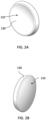
FIGS. 2A-2D are illustrations showing various views of the mobile bearing component of the glenoid bearing implant system of the present disclosure. -
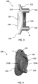
FIG. 3 is an cross-sectional illustration of the glenoid bearing implant system shown inFIG. 1A . -
FIG. 4 is an illustration showing the bond-contacting surface side of the glenoid bearing implant system shown inFIG. 1A . -
FIG. 5 is an illustration showing another embodiment of a tray component of the glenoid bearing implant system of the present disclosure. -
FIG. 6 is an illustration sowing a glenoid bearing implant system that includes the tray component shown inFIG. 5 according to another embodiment. -
FIG. 7 is an illustration showing an isometric view of another example of the glenoid bearing implant system. -
FIGS. 8A-8C are illustrations showing cross-sectional views of the glenoid bearing implant system ofFIG. 7 . -
FIG. 9 is an illustration showing an isometric view of another example of the glenoid bearing implant system. -
FIGS. 10A-10C are illustrations showing cross-sectional views of the glenoid bearing implant system ofFIG. 9 . - This description of the exemplary embodiments is intended to be read in connection with the accompanying drawings, which are to be considered part of the entire written description. The drawing figures are not necessarily to scale and certain features may be shown exaggerated in scale or in somewhat schematic form in the interest of clarity and conciseness. In the description, relative terms such as "horizontal," "vertical," "up," "down," "top" and "bottom" as well as derivatives thereof (e.g., "horizontally," "downwardly," "upwardly," etc.) should be construed to refer to the orientation as then described or as shown in the drawing figure under discussion. These relative terms are for convenience of description and normally are not intended to require a particular orientation. Terms including "inwardly" versus "outwardly," "longitudinal" versus "lateral" and the like are to be interpreted relative to one another or relative to an axis of elongation, or an axis or center of rotation, as appropriate. Terms concerning attachments, coupling and the like, such as "connected" and "interconnected," refer to a relationship wherein structures are secured or attached to one another either directly or indirectly through intervening structures, as well as both movable or rigid attachments or relationships, unless expressly described otherwise. When only a single machine is illustrated, the term "machine" shall also be taken to include any collection of machines that individually or jointly execute a set (or multiple sets) of instructions to perform any one or more of the methodologies discussed herein. The term "operatively connected" is such an attachment, coupling or connection that allows the pertinent structures to operate as intended by virtue of that relationship. In the claims, means-plus-function clauses, if used, are intended to cover the structures described, suggested, or rendered obvious by the written description or drawings for performing the recited function, including not only structural equivalents but also equivalent structures.
- Provided herein are various improved glenoid bearing implants that have articulation surface that is configured to engage with an anatomical humeral head or a humeral component of a shoulder replacement implant system. Therefore, references to "a humeral head" as used herein should be construed to include both an anatomical humeral head as well as implant humeral head. Particularly, the improved glenoid bearing implant system disclosed herein comprises a tray component that is configured to be secured to a surface on a glenoid of a patient that is appropriately prepared and a bearing component that is not afixed to the tray component but rather configured to slidingly engage the tray component so that the bearing component is positioned between the tray component and the patient's humeral head when the glenoid implant system is implanted in the patient's shoulder. The bearing component in this position is relatively unconstrained while in engagement with the humeral head and the tray component and can slide about against the tray component through the patient's articulation of the shoulder joint. As will be described below, the implant components can be configured to limit the range of motion for the bearing component.
- Referring to
FIGS. 1A-4 , an embodiment of an improvedglenoid implant system 100 for implantation in a glenoid according to the present disclosure is provided. Theglenoid implant system 100 comprises thetray component 120 and thebearing component 130. Thetray component 120 includes a bone-facingsurface 122 and a bearing-facingsurface 123 on the opposite side of the bone-facingsurface 122. Thebearing component 130 includes an articulatingsurface 132 and aback side 133 on the opposite side of the articulatingsurface 132. - The
backside 133 of thebearing component 130 and the bearing-facingsurface 123 of thetray component 120 have surfaces that are configured to engage each other in a sliding manner. The surface of thebackside 133 has a generally convex contour and the bearing-facingsurface 123 has a corresponding generally concave surface contour. - The articulating
surface 132 of thebearing component 130 is generally concave. The articulatingsurface 132 is configured for engaging a convex humeral head and theback side 133 is generally convex and is configured for engaging the bearing-facing surface. - In some embodiments, the
back side 133 of thebearing component 130 can be a spherical surface having a curvature defined by a first radius of curvature. In some embodiments, the bearing-facingsurface 123 of the tray component can be a spherical surface having a curvature defined by the first radius of curvature. - In some embodiments, the
glenoid implant system 100 can be provided with a motion limiting feature that limits the range of motion of thebearing component 130 while thebearing component 130 slides about on thetray component 120 while a convex humeral head articulates against the articulating surface after theglenoid implant system 100 has been implanted in a patient. - In some embodiments, the bearing-facing
surface 123 has a complex contour defined by more than one radii of curvature. For example, the bearing-facingsurface 123 in the central region can be defined by the first radius of curvature and the bearing-facingsurface 123 along the periphery surrounding the central region can be defined by a second radius of curvature that is smaller than the first radius of curvature. This results in the central region that is flatter than the periphery and the surface of the periphery form a steeper curved surface surrounding the central region. The central region of the bearing-facingsurface 123 is where thebearing component 130 is generally engaged and slides about relative to thetray component 120. Thus, as thebearing component 130 slides toward the periphery of thetray component 120 the bearing-facingsurface 123 presents a steeper curvature surface and hinders or prevents thebearing component 130 from sliding further. Therefore, the smaller radius of curvature along the periphery of the bearing-facingsurface 123 functions to limit the range of motion for thebearing component 130 to keep thebearing component 130 engaged to thetray component 120 during a patient's shoulder joint articulation after theglenoid implant system 100 is implanted in the patient's shoulder. - Referring to
FIGS. 5-6 , another example of a motion limiting feature is disclosed. In these embodiments, the bearing-facingsurface 123 of thetray component 120 comprises aridge 125 that extends along the bearing-facing surface's perimeter and is raised from the bearing-facingsurface 123 in the direction leading away from the bone-facingsurface 123 as shown. Theridge 125 functions as a retaining wall or a bumper that keeps thebearing component 130 engaging the bearing-facingsurface 123 and keep thebearing component 130 from sliding off the surface of thetray component 120 when theglenoid implant system 100 is installed in a patient. - In some embodiments, the
ridge 125 can extend completely around the perimeter of the bearing-facingsurface 123 without any breaks as shown in the example shown inFIGS. 5 and 6 . In some embodiments, theridge 125 can be discontinuous. In other words, theridge 125 can include one or more breaks. If there are more than one break, theridge 125 will comprise two or more ridge segments that extend along the perimeter of the bearing-facingsurface 123. - Referring to
FIG. 7 , aglenoid implant system 200 according to another embodiment that incorporates another example of a motion limiting feature is disclosed. Theglenoid implant system 200 comprises abearing component 230 and atray component 220. Thetray component 220 includes a bone-facingsurface 222 and a bearing-facingsurface 223 on the opposite side of the bone-facingsurface 222. Thebearing component 230 includes an articulatingsurface 232 and aback side 233 on the opposite side of the articulatingsurface 232. - The
backside 233 of thebearing component 230 and the bearing-facingsurface 223 of thetray component 220 have surfaces that are configured to engage each other in a sliding manner but with a predefined limited range of motion for thebearing component 230 so that the outer edges of thebearing component 230 does not travel beyond the perimeter of thetray component 220. The surface of thebackside 233 has a generally convex contour and the bearing-facingsurface 223 has a complementary generally concave surface contour but each is provided with a motion limiting feature that cooperate with one another. - The motion limiting feature on the
backside 233 of the bearing component is aboss 235. The motion limiting feature on the bearing-facingsurface 223 of thetray component 220 is acorresponding pocket 225. Thepocket 225 has an opening that is larger than theboss 235 so that when thebackside 233 of thebearing component 230 engages the bearing-facingsurface 223 of the tray component, theboss 235 is completely received in thepocket 225 and allow thebearing component 230 to slide about against the bearing-facingsurface 223. -
FIGS. 8A-8C show cross-sectional views of thebearing component 230 engaged with thetray component 220 where theboss 235 is received within thepocket 225. InFIG. 8A , thebearing component 230 is situated so that theboss 235 is inside thepocket 225 without contacting the edges of thepocket 225. InFIG. 8B , thebearing component 230 is slid upward in the maximum amount possible until theboss 235 is in contact with the edge of thepocket 225. In this context, the direction "up" in "upward" refers to the direct toward the top of the page containingFIG. 8B . InFIG. 8C , thebearing component 230 is slid downward in the maximum amount possible until theboss 235 is in contact with the edge of thepocket 225. In this context, the direction "down" in "downward" refers to the direction toward the bottom of the page containingFIG. 8C . - Referring to
FIG. 9 , aglenoid implant system 300 according to another embodiment that incorporates another example of a motion limiting feature is disclosed. Theglenoid implant system 300 comprises abearing component 330 and atray component 320. Thetray component 320 includes a bone-facingsurface 322 and a bearing-facingsurface 323 on the opposite side of the bone-facingsurface 322. Thebearing component 330 includes an articulatingsurface 332 and aback side 333 on the opposite side of the articulatingsurface 332. - The
backside 333 of thebearing component 330 and the bearing-facingsurface 323 of thetray component 320 have surfaces that are configured to engage each other in a sliding manner but with a predefined limited range of motion for thebearing component 330 so that the outer edges of thebearing component 330 does not travel beyond the perimeter of thetray component 320. The surface of thebackside 333 has a generally convex contour and the bearing-facingsurface 323 has a complementary generally concave surface contour but each is provided with a motion limiting feature that cooperate with one another. - In the
glenoid implant system 300, the motion limiting features on thebearing component 330 and thetray component 320 are opposite of those in theglenoid implant system 200. The motion limiting feature on thebackside 333 of the bearing component is apocket 335. The motion limiting feature on the bearing-facingsurface 323 of thetray component 320 is acorresponding boss 325. Thepocket 335 has an opening that is larger than theboss 325 so that when thebackside 333 of thebearing component 330 engages the bearing-facingsurface 323 of the tray component, theboss 325 is completely received in thepocket 335 and allow thebearing component 330 to slide about against the bearing-facingsurface 323. -
FIGS. 10A-10C show cross-sectional views of thebearing component 330 engaged with thetray component 320 where theboss 325 is received within thepocket 335. InFIG. 10A , thebearing component 330 is situated so that theboss 325 is inside thepocket 335 without contacting the edges of thepocket 335. InFIG. 10B , thebearing component 330 is slid upward in the maximum amount possible until theboss 325 is in contact with the edge of thepocket 335. In this context, the direction "up" in "upward" refers to the direct toward the top of the page containingFIG. 10B . InFIG. 10C , thebearing component 330 is slid downward in the maximum amount possible until theboss 325 is in contact with the edge of thepocket 335. In this context, the direction "down" in "downward" refers to the direction toward the bottom of the page containingFIG. 10C . - In the examples shown in
FIGS. 7 and9 , theboss pocket boss respective pocket pocket bearing component bearing component pocket pocket boss bearing component pocket - In some embodiments, the bearing
components - Referring to
FIGS. 3, 4 ,8A , and10A in some embodiments, the bone-facingsurface tray component surface surface tray component - In some embodiments, the bone-facing
surface surface FIGS. 3, 4 ,8A , and10A . - In some embodiments, the one or more peripheral fixation features can be
posts surface - In some embodiments, the one or more peripheral fixation features is an
annular ring annular ring FIGS. 3 and 4 , theannular ring 155 structure is interrupted by twoposts 150 and defines theannular ring 155 into twosegments more posts 150 can extend from theannular ring 155. Theannular ring 255 of thetray component 220, and theannular ring 355 of thetray component 320 are configured in a similar manner. - In some embodiments, the one or more peripheral fixation features 150, 155, 250, 255, 350, 355 also can comprise a layer of a porous material so that at least some portion of the bone-facing
surface - In some embodiments, the
bearing component - In some embodiments, the
tray component surface tray component tray component - Various aspects and embodiments of the present invention are defined by the following numbered clauses:
- 1. A glenoid implant system comprising:
- a tray component that comprises a bone-facing surface and a bearing-facing surface on opposite side of the bone-facing surface; and
- a bearing component that comprises an articulating surface that is generally concave and a back side on opposite side of the articulating surface that is generally convex,
- wherein the articulating surface is configured for engaging a convex humeral head and the back side is configured for engaging the bearing-facing surface of the tray component enabling the bearing component to slide about on the tray component while the convex humeral head articulates against the articulating surface.
- 2. The glenoid implant system of clause 1, wherein the tray component is formed of a metal.
- 3. The glenoid implant system of clause 1 or 2, wherein the bearing component is formed of a high-modulus polymer.
- 4. The glenoid implant system of any of the clauses 1 - 3, wherein the bearing component is formed of high-modulus polyethylene (HMPE) or ultra-high-molecular-weight polyethylene (UHMWPE).
- 5. The glenoid implant system of any of the clauses 1 - 4, wherein the bone-facing surface of the tray component comprises at least a portion that comprises a layer of a porous material that can promote bone in-growth.
- 6. The glenoid implant system of any of the clauses 1 - 5, wherein the bone-facing surface of the tray component comprises at least a portion that has a roughened surface that can accept bone cement for bonding with native bone.
- 7. The glenoid implant system of any of the clauses 1 - 6, wherein the bone-facing surface further comprises one or more peripheral fixation features extending therefrom in a direction that is away from the bearing-facing surface.
- 8. The glenoid implant system of clause 7, wherein the one or more peripheral fixation features is an annular ring.
- 9. The glenoid implant system of clause 8, wherein the annular ring is configured into two or more segments.
- 10. The glenoid implant system of clause 7 or 8, wherein the one or more peripheral fixation features are posts.
- 11. The glenoid implant system of any of the clauses 8 - 10, wherein the one or more peripheral fixation features further comprising one or more posts.
- 12. The glenoid implant system of clause 11, wherein the one or more posts extend from the annular ring.
- 13. The glenoid implant system of any of the clauses 7 - 12, wherein the one or more peripheral fixation features comprise a layer of a porous material that can promote bone in-growth.
- 14. The glenoid implant system of any of the clauses 1 - 13, wherein the back side of the bearing component is a spherical surface having a curvature defined by a first radius of curvature.
- 15. The glenoid implant system of clause 14, comprising a motion limiting feature that limits the range of motion of the bearing component sliding about the bearing-facing surface of the tray component.
- 16. The glenoid implant system of clause 15, wherein the motion limiting feature comprises the bearing-facing surface being defined by more than one radii of curvature wherein the bearing-facing surface comprises:
- a central region that is a spherical surface having a curvature defined by the first radius of curvature; and
- a peripheral portion that is a spherical surface having a curvature defined by a second radius of curvature that is smaller than the first radius of curvature.
- 17. The glenoid implant system of clause 15 or 16, wherein the motion limiting feature comprises a continuous ridge that extends along the bearing-facing surface's perimeter and is raised from the bearing-facing surface away from the bone-facing surface.
- 18. The glenoid implant system of any of the clauses 15 to 17, wherein the motion limiting feature comprises two or more ridge segments that extend along the bearing-facing surface's perimeter and are raised from the bearing-facing surface away from the bone-facing surface.
- 19. The glenoid implant system of any of the clauses 15 to 18, wherein the motion limiting feature comprises a boss provided on the back side of the articulating component; and a pocket provided on the bearing-facing surface of the tray component, wherein the pocket has an opening that is larger than the boss.
- 20. The glenoid implant system of any of the clauses 15 to 19, wherein the motion limiting
feature comprises a pocket provided on the back side of the articulating component; and a boss provided on the bearing-facing surface of the tray component, wherein the pocket has an opening that is larger than the boss. - Also within the scope of this disclosure is a surgical kit that includes one or more of the glenoid implant systems embodiments described herein.
- Although the devices, kits, systems, and methods have been described in terms of exemplary embodiments, they are not limited thereto. Rather, the appended claims should be construed broadly, to include other variants and embodiments of the devices, kits, systems, and methods, which may be made by those skilled in the art without departing from the scope and range of equivalents of the devices, kits, systems, and methods.
Claims (15)
- A glenoid implant system comprising:a tray component that comprises a bone-facing surface and a bearing-facing surface on opposite side of the bone-facing surface; anda bearing component that comprises an articulating surface that is generally concave and a back side on opposite side of the articulating surface that is generally convex,wherein the articulating surface is configured for engaging a convex humeral head and the back side is configured for engaging the bearing-facing surface of the tray component enabling the bearing component to slide about on the tray component while the convex humeral head articulates against the articulating surface.
- The glenoid implant system of Claim 1, wherein the tray component is formed of a metal.
- The glenoid implant system of Claim 1 or 2, wherein the bearing component is formed of a high-modulus polymer, and/or wherein the bearing component is formed of high-modulus polyethylene (HMPE) or ultra-high-molecular-weight polyethylene (UHMWPE).
- The glenoid implant system of any of the Claims 1 to 3, wherein the bone-facing surface of the tray component comprises at least a portion that comprises a layer of a porous material that can promote bone in-growth, and/or wherein the bone-facing surface of the tray component comprises at least a portion that has a roughened surface that can accept bone cement for bonding with native bone.
- The glenoid implant system of any of the Claims 1 to 4, wherein the bone-facing surface further comprises one or more peripheral fixation features extending therefrom in a direction that is away from the bearing-facing surface.
- The glenoid implant system of Claim 5, wherein the one or more peripheral fixation features is an annular ring.
- The glenoid implant system of Claim 6, wherein the annular ring is configured into two or more segments.
- The glenoid implant system of Claim 5, wherein the one or more peripheral fixation features are posts.
- The glenoid implant system of Claim 6 or 7, wherein the one or more peripheral fixation features further comprising one or more posts.
- The glenoid implant system of Claim 9, wherein the one or more posts extend from the annular ring.
- The glenoid implant system of any of the Claims 5 to 10, wherein the one or more peripheral fixation features comprise a layer of a porous material that can promote bone in-growth.
- The glenoid implant system of any of the Claims 1 to 11, wherein the back side of the bearing component is a spherical surface having a curvature defined by a first radius of curvature.
- The glenoid implant system of Claim 12, comprising a motion limiting feature that limits the range of motion of the bearing component sliding about the bearing-facing surface of the tray component.
- The glenoid implant system of Claim 13, wherein the motion limiting feature comprises the bearing-facing surface being defined by more than one radii of curvature wherein the bearing-facing surface comprises:a central region that is a spherical surface having a curvature defined by the first radius of curvature; anda peripheral portion that is a spherical surface having a curvature defined by a second radius of curvature that is smaller than the first radius of curvature.
- The glenoid implant system of Claim 13 or 14, wherein the motion limiting feature comprises at least one of:- a continuous ridge that extends along the bearing-facing surface's perimeter and is raised from the bearing-facing surface away from the bone-facing surface;- two or more ridge segments that extend along the bearing-facing surface's perimeter and are raised from the bearing-facing surface away from the bone-facing surface;- a boss provided on the back side of the articulating component; and a pocket provided on the bearing-facing surface of the tray component, wherein the pocket has an opening that is larger than the boss; and- a pocket provided on the back side of the articulating component; and a boss provided on the bearing-facing surface of the tray component, wherein the pocket has an opening that is larger than the boss.
Applications Claiming Priority (2)
| Application Number | Priority Date | Filing Date | Title |
|---|---|---|---|
| US202163262567P | 2021-10-15 | 2021-10-15 | |
| US18/046,297 US20230119337A1 (en) | 2021-10-15 | 2022-10-13 | Mobile bearing anatomic glenoid |
Publications (1)
| Publication Number | Publication Date |
|---|---|
| EP4166115A1 true EP4166115A1 (en) | 2023-04-19 |
Family
ID=83847835
Family Applications (1)
| Application Number | Title | Priority Date | Filing Date |
|---|---|---|---|
| EP22201630.5A Pending EP4166115A1 (en) | 2021-10-15 | 2022-10-14 | Mobile bearing anatomic glenoid |
Country Status (2)
| Country | Link |
|---|---|
| US (1) | US20230119337A1 (en) |
| EP (1) | EP4166115A1 (en) |
Citations (4)
| Publication number | Priority date | Publication date | Assignee | Title |
|---|---|---|---|---|
| GB2297257A (en) * | 1995-01-24 | 1996-07-31 | Corin Medical Ltd | Shoulder prosthesis with meniscal component |
| FR2821545A1 (en) * | 2001-03-02 | 2002-09-06 | Aston Medical Ltd | PROSTHETIC ASSEMBLY FOR THE SHOULDER JOINT |
| FR2825263A1 (en) * | 2001-05-30 | 2002-12-06 | Tecknimed | Shoulder joint prosthesis has cap on humerus to engage socket with movement limiting stop surfaces |
| FR2955248A1 (en) * | 2010-01-21 | 2011-07-22 | Tornier Sa | Shoulder prosthesis glenoidal component for use on coil of scapula, has fixation base provided with anchoring unit, and plate defining articular surface on plate opposed face, where articular surface cooperates with humeral head |
-
2022
- 2022-10-13 US US18/046,297 patent/US20230119337A1/en active Pending
- 2022-10-14 EP EP22201630.5A patent/EP4166115A1/en active Pending
Patent Citations (4)
| Publication number | Priority date | Publication date | Assignee | Title |
|---|---|---|---|---|
| GB2297257A (en) * | 1995-01-24 | 1996-07-31 | Corin Medical Ltd | Shoulder prosthesis with meniscal component |
| FR2821545A1 (en) * | 2001-03-02 | 2002-09-06 | Aston Medical Ltd | PROSTHETIC ASSEMBLY FOR THE SHOULDER JOINT |
| FR2825263A1 (en) * | 2001-05-30 | 2002-12-06 | Tecknimed | Shoulder joint prosthesis has cap on humerus to engage socket with movement limiting stop surfaces |
| FR2955248A1 (en) * | 2010-01-21 | 2011-07-22 | Tornier Sa | Shoulder prosthesis glenoidal component for use on coil of scapula, has fixation base provided with anchoring unit, and plate defining articular surface on plate opposed face, where articular surface cooperates with humeral head |
Also Published As
| Publication number | Publication date |
|---|---|
| US20230119337A1 (en) | 2023-04-20 |
Similar Documents
| Publication | Publication Date | Title |
|---|---|---|
| US20230218404A1 (en) | Shoulder arthroplasty systems and configurations for components thereof | |
| US8663335B2 (en) | Shoulder prosthetic | |
| JP5769320B2 (en) | Interlocking reverse hip joint and revision prosthesis | |
| US8591596B2 (en) | Semi-constrained ankle prosthesis having a rotating bearing insert | |
| US6217616B1 (en) | Elbow prosthesis | |
| EP2775963B1 (en) | Prosthesis component | |
| US20050278033A1 (en) | Total shoulder prosthesis or inverted type | |
| EP3405141B1 (en) | Constrained dual mobility hip prosthesis | |
| US8142511B2 (en) | Bi-material prosthesis component | |
| EP2379015B1 (en) | Medical device | |
| US20230119337A1 (en) | Mobile bearing anatomic glenoid | |
| EP3405143A1 (en) | Shoulder joint prosthesis | |
| WO2024126979A1 (en) | A dual mobility prosthesis for implantation into the acetabulum | |
| US20240074864A1 (en) | Dual mobility acetabular implant for hip revision surgery | |
| EP4093336B1 (en) | Mobile bearing reversed humeral implant | |
| JP2023528062A (en) | hip implant system | |
| WO2024259475A1 (en) | A temporomandibular joint replacement implant |
Legal Events
| Date | Code | Title | Description |
|---|---|---|---|
| PUAI | Public reference made under article 153(3) epc to a published international application that has entered the european phase |
Free format text: ORIGINAL CODE: 0009012 |
|
| STAA | Information on the status of an ep patent application or granted ep patent |
Free format text: STATUS: REQUEST FOR EXAMINATION WAS MADE |
|
| 17P | Request for examination filed |
Effective date: 20221014 |
|
| AK | Designated contracting states |
Kind code of ref document: A1 Designated state(s): AL AT BE BG CH CY CZ DE DK EE ES FI FR GB GR HR HU IE IS IT LI LT LU LV MC ME MK MT NL NO PL PT RO RS SE SI SK SM TR |
|
| RBV | Designated contracting states (corrected) |
Designated state(s): AL AT BE BG CH CY CZ DE DK EE ES FI FR GB GR HR HU IE IS IT LI LT LU LV MC ME MK MT NL NO PL PT RO RS SE SI SK SM TR |
|
| STAA | Information on the status of an ep patent application or granted ep patent |
Free format text: STATUS: EXAMINATION IS IN PROGRESS |
|
| 17Q | First examination report despatched |
Effective date: 20240917 |