EP4166015A1 - Electronic atomizing device and atomizer thereof - Google Patents
Electronic atomizing device and atomizer thereof Download PDFInfo
- Publication number
- EP4166015A1 EP4166015A1 EP22198369.5A EP22198369A EP4166015A1 EP 4166015 A1 EP4166015 A1 EP 4166015A1 EP 22198369 A EP22198369 A EP 22198369A EP 4166015 A1 EP4166015 A1 EP 4166015A1
- Authority
- EP
- European Patent Office
- Prior art keywords
- liquid
- heating
- top cover
- airway
- liquid return
- Prior art date
- Legal status (The legal status is an assumption and is not a legal conclusion. Google has not performed a legal analysis and makes no representation as to the accuracy of the status listed.)
- Pending
Links
Images


Classifications
-
- A—HUMAN NECESSITIES
- A24—TOBACCO; CIGARS; CIGARETTES; SIMULATED SMOKING DEVICES; SMOKERS' REQUISITES
- A24F—SMOKERS' REQUISITES; MATCH BOXES; SIMULATED SMOKING DEVICES
- A24F40/00—Electrically operated smoking devices; Component parts thereof; Manufacture thereof; Maintenance or testing thereof; Charging means specially adapted therefor
- A24F40/40—Constructional details, e.g. connection of cartridges and battery parts
-
- A—HUMAN NECESSITIES
- A24—TOBACCO; CIGARS; CIGARETTES; SIMULATED SMOKING DEVICES; SMOKERS' REQUISITES
- A24F—SMOKERS' REQUISITES; MATCH BOXES; SIMULATED SMOKING DEVICES
- A24F40/00—Electrically operated smoking devices; Component parts thereof; Manufacture thereof; Maintenance or testing thereof; Charging means specially adapted therefor
- A24F40/10—Devices using liquid inhalable precursors
-
- A—HUMAN NECESSITIES
- A24—TOBACCO; CIGARS; CIGARETTES; SIMULATED SMOKING DEVICES; SMOKERS' REQUISITES
- A24F—SMOKERS' REQUISITES; MATCH BOXES; SIMULATED SMOKING DEVICES
- A24F40/00—Electrically operated smoking devices; Component parts thereof; Manufacture thereof; Maintenance or testing thereof; Charging means specially adapted therefor
- A24F40/40—Constructional details, e.g. connection of cartridges and battery parts
- A24F40/46—Shape or structure of electric heating means
-
- A—HUMAN NECESSITIES
- A24—TOBACCO; CIGARS; CIGARETTES; SIMULATED SMOKING DEVICES; SMOKERS' REQUISITES
- A24F—SMOKERS' REQUISITES; MATCH BOXES; SIMULATED SMOKING DEVICES
- A24F40/00—Electrically operated smoking devices; Component parts thereof; Manufacture thereof; Maintenance or testing thereof; Charging means specially adapted therefor
- A24F40/40—Constructional details, e.g. connection of cartridges and battery parts
- A24F40/48—Fluid transfer means, e.g. pumps
- A24F40/485—Valves; Apertures
-
- A—HUMAN NECESSITIES
- A24—TOBACCO; CIGARS; CIGARETTES; SIMULATED SMOKING DEVICES; SMOKERS' REQUISITES
- A24F—SMOKERS' REQUISITES; MATCH BOXES; SIMULATED SMOKING DEVICES
- A24F40/00—Electrically operated smoking devices; Component parts thereof; Manufacture thereof; Maintenance or testing thereof; Charging means specially adapted therefor
- A24F40/20—Devices using solid inhalable precursors
Definitions
- the present invention relates to the technical field of electronic atomizing devices, and in particular, to an atomizer and an electronic atomizing device.
- Atomizer is an important component of an electronic atomizing device that can vaporize liquid.
- gas formed through the atomizing can be outputted along a main airway of the atomizer.
- a part of the gas located in the main airway is cooled down and liquefied, forming condensate in a liquid state.
- the part of condensate is outputted with the vapor in the main airway in an operating process of the atomizer, resulting in liquid leakage of the atomizer.
- a structure for guiding the condensate in the main airway to a heating top cover may be provided, to alleviate the leakage of the condensate.
- An atomizer includes a heating top cover and a heating body, the heating top cover includes an airway corner, and a liquid return groove extending from the heating top cover to the heating body is provided at the airway corner.
- the atomizer includes a main body, the main body includes a main airway, the heating top cover is provided in the main body, a top cover airway is formed between the heating top cover and the main body, and the top cover airway is in communication with the main airway through the airway corner.
- a side wall of the liquid return groove adjacent to an atomizing surface of the heating body is provided with a side wall opening, and the side wall opening is configured to allow liquid to pass through.
- At least one side wall of the liquid return groove is provided with an inclined surface, and the inclined surface is configured to guide liquid to flow to the heating body.
- At least a part of the heating body is accommodated in the liquid return groove, and the inclined surface gradually approaches the heating body in a direction away from a bottom wall of the liquid return groove.
- the heating top cover is provided with a liquid guide groove, the liquid guide groove is in communication with the liquid return groove, and the liquid guide groove is configured to guide liquid to flow to the liquid return groove.
- one end of the liquid guide groove is located at the airway corner, and the other end is located on a side of the heating top cover adjacent to the atomizing surface.
- a plurality of liquid return grooves are spaced apart at the airway corner.
- a number of liquid return grooves located in a middle portion of the heating top cover is M, and a number of liquid return grooves located at an edge of the heating top cover is N, and M is greater than or equal to N.
- An electronic atomizing device includes a power supply assembly and the foregoing atomizer, where the power supply assembly is electrically connected to the heating body of the atomizer.
- the liquid return groove is provided at the airway corner, liquid detained at the airway corner is guided to the heating body for secondary atomizing of the liquid.
- the arrangement of the liquid return groove may also effectively prevent the liquid from accumulating and detaining, thereby avoiding the liquid from entering the main airway and leaking during an atomizing process.
- the foregoing atomizer has a low cost and a simple structure, and enables the electronic atomizing device to have better resistance against liquid leakage during using.
- first and second are used merely for the purpose of description, and shall not be construed as indicating or implying relative importance or implying a number of indicated technical features. Therefore, features defining “first” and “second” can explicitly or implicitly include at least one of the features. In description of the present invention, “multiple” means at least two, such as two and three unless it is specifically defined otherwise.
- connection may be a fixed connection, a detachable connection, or an integral connection; or the connection may be a mechanical connection or an electrical connection; or the connection may be a direct connection, an indirect connection through an intermediary, or internal communication between two elements or a mutual action relationship between two elements, unless otherwise specified explicitly.
- connection may be a fixed connection, a detachable connection, or an integral connection; or the connection may be a mechanical connection or an electrical connection; or the connection may be a direct connection, an indirect connection through an intermediary, or internal communication between two elements or a mutual action relationship between two elements, unless otherwise specified explicitly.
- a first characteristic "on” or “under” a second characteristic may be the first characteristic in direct contact with the second characteristic, or the first characteristic in indirect contact with the second characteristic by using an intermediate medium.
- the first feature being located “above” the second feature may be the first feature being located directly above or obliquely above the second feature, or may simply indicate that the first feature is higher in level than the second feature.
- the first feature "under”, “below” and “down” the second feature may be that the first feature is directly below or obliquely below the second feature, or simply indicates that a horizontal height of the first feature is less than that of the second feature.
- An embodiment of the present invention provides an electronic atomizing device, including an atomizer and a power supply.
- the power supply is configured to supply power to the atomizer, so that the atomizer can heat floral, foliar, and herbal liquid to form gases through atomizing.
- the power supply can be selected in the related art.
- the atomizer according to an embodiment of the present invention includes a main body 100, a heating top cover 200, and a heating body 300.
- the heating top cover 200 and the heating body 300 are connected to each other and are provided in the main body 100.
- the main body 100 includes a main airway 110, and the main airway 110 is in communication with an external atmosphere.
- the main airway 110 is configured to output atomizing gas after atomizing the liquid, and then guide the atomizing gas into the mouth of a user.
- the main body 100 includes a hollow first housing 120 and a hollow second housing 130.
- the first housing 120 is at least partially located inside the second housing 130.
- the first housing 120 and the second housing 130 are integrally formed or may be a structure in which the first housing 120 and the second housing 130 are separately formed and then assembled into a whole.
- a hollow portion of the first housing 120 forms the main airway 110.
- a liquid reservoir 140 for storing liquid is formed between the first housing 120 and the second housing 130.
- a liquid outlet 141 is provided on a side of the liquid reservoir 140, and the liquid in the liquid reservoir 140 can flow out from the liquid outlet 141.
- the heating body 300 includes a heating surface 310, and a heating core absorbing liquid is provided on the heating surface 310.
- the heating core can be electrically connected to the power supply, so that when the power supply supplies power, the heating core generates heat and atomizes liquid that permeates into the heating surface 310.
- the heating top cover 200 includes a liquid passing channel 260 (shown in FIG. 7 ).
- a side of the liquid passing channel 260 is provided with a liquid inlet 250 corresponding to the liquid outlet 141, so that the liquid can flow into the liquid inlet 250 along the liquid outlet 141 and enter the liquid passing channel 260.
- the other side of the liquid passing channel 260 is in communication with a side of the heating body 300 away from the heating surface 310, so that the liquid can be in contact with the heating body 300.
- a top cover airway 210 is formed between the heating top cover 200 and an inner wall of the main body 100.
- the heating top cover 200 includes an airway corner 220, and the top cover airway 210 is in communication with the main airway 110 through the airway corner 220.
- the heating top cover 200 can be U-shaped.
- a side of the heating top cover 200 can be provided with two liquid inlets 250 that are spaced apart.
- a recess 201 is formed in a middle portion of the side of the heating top cover 200 in a direction of approaching the heating body 300 (that is, a Z-axis direction showing in FIG. 1 ).
- a gap is formed between the recess 201 and the main body 100, so as to form the airway corner 220, and the airway corner 220 is in communication with the main airway 110.
- the top cover airway 210 can be formed between a side wall of the heating top cover 200 and the second housing 130 of the main body 100.
- the liquid (that is, condensate) formed through condensation of gas in the top cover airway 210 can flow back to the airway corner 220.
- a shape and a structure of the top cover airway 210 are not specifically limited, and can be configured according to actual conditions.
- the liquid entering the liquid passing channel 260 from the liquid reservoir 140 is atomized by the heating of the heating body 300, so that gas is obtained.
- the gas enters the main airway 110 through the airway corner 220 along the top cover airway 210, and moves to the outside of the main body 100 for the user to inhale.
- a part of the atomized gas may be cooled down and liquefied during the movement, thus forming condensate.
- the condensate will return to the airway corner 220 along an inner wall of the main airway 110 (that is, an inner wall of the first housing 120).
- a vertical direction that is, the Z-axis direction in FIG.
- the liquid will be accumulated at the airway corner 220.
- the accumulated liquid may be discharged from the main airway 110 as driven by an air flow during inhaling, causing liquid leakage, further resulting in poor reliability in resistance against the liquid leakage of the atomizer during inhaling.
- a liquid return groove 230 extending to the heating body 300 is provided at the airway corner 220, so as to improve the reliability in resistance of the atomizer against liquid leakage during use.
- the liquid return groove 230 can enable the liquid accumulated at the airway corner 220 to return to the heating body 300.
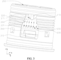
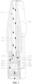
- the liquid return groove 230 is located in the recess 201 of the heating top cover 200, and a side of the liquid return groove 230 is in communication with the heating body 300, so that the liquid can flow to the heating body 300 along the liquid return groove 230, as shown by arrows in FIG. 2 and FIG. 3 .
- the liquid on a surface of the heating body 300 can move into the heating body 300, and the liquid can be atomized again on the surface of the heating body 300 to form the gas.
- the heating body 300 can be made of a material such as porous ceramic or porous metal, but is not limited hereto, as long as it can implement secondary atomizing after the liquid comes into contact with the surface of the heating body 300.
- a groove depth direction of the liquid return groove 230 is defined as a depth direction (an X-axis direction in FIG. 1 to FIG. 4 ) of the liquid return groove 230.
- a direction of the liquid return groove 230 along the heating top cover 200 to the heating surface 310 of the heating body 300 is defined as a length direction (a Z-axis direction in FIG. 1 to FIG. 5 ) of the liquid return groove 230.
- a direction perpendicular to both the length direction and the depth direction is defined as a width direction (a Y-axis direction in FIG. 1 to FIG. 5 ) of the liquid return groove 230.
- a shape and a size of the liquid return groove 230 can both be adjusted according to actual conditions.
- the shape of the liquid return groove 230 is cuboid or cuboid-like.
- the liquid return groove 230 is provided on a side of the heating top cover 200 adjacent to the heating body 300.
- the surface of the heating body 300 can be exposed to the airway corner 220 from the liquid return groove 230.
- the liquid return groove 230 is formed by enclosing a bottom wall 231 and side walls.
- the bottom wall 231 (shown in FIG. 6 to FIG. 8 ) is located on a side of the liquid return groove 230 along a depth direction and adjacent to the heating body.
- the bottom wall 231 of the liquid return groove 230 penetrates through the heating top cover 200, so that the liquid return groove 230 forms a through hole in the X-axis direction.
- the side walls may include a first side wall 233, a second side wall 234, a third side wall 235, and a fourth side wall 236 that are connected end to end.
- the first side wall 233 and the third side wall 235 are provided opposite to each other in the length direction (Z-axis direction) of the liquid return groove 230.
- the first side wall 233 is located on a side that is away from the heating surface 310.
- the third side wall 235 is located on a side adjacent to the heating surface 310.
- the second side wall 234 and the fourth side wall 236 are provided opposite to each other in the width direction (Y-axis direction) of the liquid return groove 230.
- the liquid return groove 230 includes a side wall opening 232, which is used for liquid to pass through.
- the third side wall 235 of the liquid return groove 230 is provided with at least one side wall opening 232, and the liquid can flow in the length direction (Z-axis direction) of the liquid return groove 230 to flow to the heating body 300 for secondary atomizing.
- the liquid can also move in the depth direction (X-axis direction) of the liquid return groove 230, so as to be adsorbed by the surface of the heating body 300 for secondary atomizing.
- At least one of the second side wall 234 and the fourth side wall 236, and the third side wall 235 are both provided with the side wall openings 232.
- the liquid can flow to the surface of the heating body 300 along any one of the side wall openings 232 for secondary atomizing.
- the side walls of the liquid return groove 230 are not all provided with a side wall opening.
- the liquid moves in the depth direction (X-axis direction) of the liquid return groove 230, so as to be adsorbed to the surface of the heating body 300 for secondary atomizing.
- At least one side wall of the liquid return groove 230 is provided with an inclined surface 237.
- the inclined surface 237 can guide the liquid to flow to the heating body 300.
- the inclined surface 237 gradually approaches the heating body 300 in a moving direction of the liquid. That is, the inclined surface 237 gradually approaches the heating body 300 in a direction from the side wall to a middle portion of the liquid return groove 230.
- An inclination angle of the inclined surface 237 can be adjusted according to actual conditions.
- the side wall of the liquid return groove 230 along the length direction of the liquid return groove 230 and away from the heating surface 310 is provided with the inclined surface 237. That is, the first side wall 233 of the liquid return groove 230 is provided with the inclined surface 237.
- the inclined surface 237 gradually approaches the heating body 300 in a direction from the first side wall 233 to the third side wall 235. The liquid can flow through the liquid return groove 230 along the inclined surface 237 provided on the first side wall 233 and flow to the surface of the heating body 300.
- first side wall 233, the second side wall 234, and the fourth side wall 236 of the liquid return groove 230 are all provided with inclined surfaces 237 to facilitate the liquid to flow into the liquid return groove 230.
- a thickness of the side wall of the liquid return groove 230 gradually decreases. In some other embodiments, in the length direction of the liquid return groove 230, a thickness of the side wall of the liquid return groove 230 remains unchanged.
- the bottom wall 231 of the liquid return groove 230 abuts against the heating body 300.
- a gap is formed between the bottom wall 231 of the liquid return groove 230 and the side wall of the heating body 300. It should be noted that a width of the gap in the depth direction of the liquid return groove 230 cannot be too large, and needs to satisfy that the surface of the liquid flowing to the groove bottom wall 231 of the liquid return groove 230 can come into contact with the surface of the heating body 300, to facilitate secondary atomizing of the liquid.
- a total width of the heating top cover 200 in the width direction of the liquid return groove 230 is defined as D.
- a portion of the heating top cover 200 located in a range of from 0.25D to 0.75D (including end points) is defined as a middle portion of the heating top cover 200.
- a portion of the heating top cover 200 that is located in a range of from 0 to 0.25D (excluding end points) or from 0.75D to D (excluding end points) is defined as an edge of the heating top cover 200.
- One or more liquid return grooves 230 can be provided.
- liquid return grooves 230 there are two or more liquid return grooves 230, and the liquid return grooves 230 are spaced apart on the heating top cover 200. In some embodiments, all of the liquid return grooves 230 are spaced apart in the width direction of the liquid return grooves 230, and gaps between adjacent liquid return grooves 230 have the same or different widths. For example, in some embodiments, the liquid return grooves 230 are equally spaced apart.
- a plurality of liquid return grooves 230 are provided, and in the width direction of the liquid return grooves 230, the number of liquid return grooves 230 that are located in the middle portion of the heating top cover 200 is M (M is a positive integer).
- the number of liquid return grooves 230 that are located at an edge of the heating top cover 200 is N (N is a positive integer), and M is greater than or equal to N.
- the liquid return grooves 230 can be arranged in one or more rows in the length direction of the liquid return grooves 230, and each row includes a plurality of liquid return grooves 230.
- the liquid return grooves 230 are arranged in one row.
- the liquid return grooves 230 may be arranged in a plurality of rows, and intervals between adjacent rows may be the same or different. In addition, the liquid return grooves 230 in each row may not be located at the same horizontal plane. In addition, the liquid return grooves 230 may have the same or different lengths and widths. For example, in some embodiments, all of the liquid return grooves 230 have the same length and the same width and are equally spaced apart.
- none of the liquid return grooves 230 have the same length and the same width, and the liquid return grooves 230 are equally spaced apart.
- a width of the liquid return groove 230 located in the middle portion of the heating top cover 200 is greater than a width of the liquid return groove 230 located at the edge of the heating top cover 200, and a length of the liquid return groove 230 located in the middle portion of the heating top cover 200 is less than a length of the liquid return groove 230 located at the edge of the heating top cover 200.
- none of the liquid return grooves 230 have the same length, but all of the liquid return grooves 230 have the same width, and the liquid return grooves 230 are equally spaced apart.
- a length of the liquid return groove 230 located in the middle portion of the heating top cover 200 is less than a length of the liquid return groove 230 located at the edge of the heating top cover 200.
- liquid return groove 230 regardless how the length of the liquid return groove 230 is configured, groove bottoms of all the liquid return grooves 230 completely or partially expose the side wall of the heating body 300. That is, the liquid return groove 230 is configured for the liquid to return to the heating body 300 from the airway corner 220.
- the liquid return grooves 230 may be provided on two opposite side walls of the heating top cover 200 in the depth direction of the liquid return grooves 230. In some other embodiments, the liquid return grooves 230 may only be provided on a specific side wall of the heating top cover 200.
- the heating top cover 200 is provided with a liquid guide groove 240.
- a side of the liquid guide groove 240 is located at the recess 201 or adjacent to the recess 201, and the other side of the liquid guide groove 240 is located on a side of the heating top cover 200 adjacent to the heating surface 310.
- the side wall of the liquid guide groove 240 may partially protrude from an outer surface of the heating top cover 200, or may be coplanar with the outer surface of the heating top cover 200.
- a convex bar 241 is provided on the heating top cover 200.
- the convex bar 241 is arranged in the length direction of the liquid return groove 230.
- a plurality of convex bars 241 are provided, and the plurality of convex bars 241 are spaced apart.
- the liquid guide groove 240 is formed between adjacent convex bars 241.
- the liquid guide groove 240 is in communication with the liquid return groove 230, so that the liquid accumulated at the airway corner 220 can flow along the liquid guide groove 240 to the liquid return groove 230, and then enter the heating body 300.
- the arrangement of the liquid guide groove 240 enables the liquid to flow to the liquid return groove 230 along a specific path in a relatively concentrated manner. That is, under the action of the liquid guide groove 240, a large amount of the liquid flows along the liquid guide groove 240 to the liquid return groove 230 for secondary atomizing. However, a small amount of the liquid may flow to the heating body 300 along a portion of the heating top cover 200 on which no liquid guide groove 240 is provided.
- a side of the liquid guide groove 240 away from the main airway 110 is in communication with the liquid return groove 230. In some other embodiments, a middle portion of the liquid guide groove 240 is in communication with the liquid return groove 230. The position of the liquid return groove 230 relative to the liquid guide groove 240 can be adjusted according to actual conditions.
- a protruding portion 270 may further provided on the recess 201 of the heating top cover 200, and the protruding portion 270 and the heating top cover 200 can be integrally formed or be connected in other manners.
- the protruding portion 270 extends in a direction of the main airway 110.
- a flange 271 may be provided at a joint between the protruding portion 270 and the recess 201 of the heating top cover 200, and a surface of the flange 271 may be an inclined flat surface or an inclined curved surface, so that the liquid flows from the recess 201 along the surface of the flange 271 to the liquid return groove 230.
- the arrangement of the protruding portion 270 can reduce a depth of the recess 201 without affecting ventilation of the airway corner 220, so as to reduce a maximum amount of the accumulated liquid.
- the liquid return groove 230 is provided on the heating top cover 200, so that the liquid accumulated at the airway corner 220 can return to the heating body 300 in the depth direction of the liquid return groove 230 for secondary atomizing.
- the foregoing arrangement can prevent the liquid from leaking out of the atomizer from the main airway 110, thereby effectively improving liquid leakage-proof ability of the atomizer and the electronic atomizing device during using.
Landscapes
- Cookers (AREA)
- Instantaneous Water Boilers, Portable Hot-Water Supply Apparatuses, And Control Of Portable Hot-Water Supply Apparatuses (AREA)
- Disinfection, Sterilisation Or Deodorisation Of Air (AREA)
- Air Humidification (AREA)
Abstract
Description
- The present invention relates to the technical field of electronic atomizing devices, and in particular, to an atomizer and an electronic atomizing device.
- Atomizer is an important component of an electronic atomizing device that can vaporize liquid. When the atomizer performs atomizing, gas formed through the atomizing can be outputted along a main airway of the atomizer.
- However, in an atomizing process performed by the atomizer, a part of the gas located in the main airway is cooled down and liquefied, forming condensate in a liquid state. The part of condensate is outputted with the vapor in the main airway in an operating process of the atomizer, resulting in liquid leakage of the atomizer. To reduce the occurrence of this case, in some atomizers, a structure for guiding the condensate in the main airway to a heating top cover may be provided, to alleviate the leakage of the condensate.
- However, in an actual atomizing process, the foregoing atomizers have poor reliability in resistance against liquid leakage during inhaling.
- Based on this, it is necessary to provide an atomizer and an electronic atomizing device to resolve the problem of poor reliability in resistance against liquid leakage of the atomizer during inhaling.
- An atomizer includes a heating top cover and a heating body, the heating top cover includes an airway corner, and a liquid return groove extending from the heating top cover to the heating body is provided at the airway corner.
- In an embodiment, the atomizer includes a main body, the main body includes a main airway, the heating top cover is provided in the main body, a top cover airway is formed between the heating top cover and the main body, and the top cover airway is in communication with the main airway through the airway corner.
- In one of the embodiments, a side wall of the liquid return groove adjacent to an atomizing surface of the heating body is provided with a side wall opening, and the side wall opening is configured to allow liquid to pass through.
- In one of the embodiments, at least one side wall of the liquid return groove is provided with an inclined surface, and the inclined surface is configured to guide liquid to flow to the heating body.
- In one of the embodiments, at least a part of the heating body is accommodated in the liquid return groove, and the inclined surface gradually approaches the heating body in a direction away from a bottom wall of the liquid return groove.
- In one of the embodiments, the heating top cover is provided with a liquid guide groove, the liquid guide groove is in communication with the liquid return groove, and the liquid guide groove is configured to guide liquid to flow to the liquid return groove.
- In one of the embodiments, one end of the liquid guide groove is located at the airway corner, and the other end is located on a side of the heating top cover adjacent to the atomizing surface.
- In one of the embodiments, a plurality of liquid return grooves are spaced apart at the airway corner.
- In one of the embodiments, a number of liquid return grooves located in a middle portion of the heating top cover is M, and a number of liquid return grooves located at an edge of the heating top cover is N, and M is greater than or equal to N.
- An electronic atomizing device includes a power supply assembly and the foregoing atomizer, where the power supply assembly is electrically connected to the heating body of the atomizer.
- In the atomizer and the electronic atomizing device, since the liquid return groove is provided at the airway corner, liquid detained at the airway corner is guided to the heating body for secondary atomizing of the liquid. The arrangement of the liquid return groove may also effectively prevent the liquid from accumulating and detaining, thereby avoiding the liquid from entering the main airway and leaking during an atomizing process. The foregoing atomizer has a low cost and a simple structure, and enables the electronic atomizing device to have better resistance against liquid leakage during using.
-
-
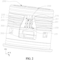
FIG. 1 is a partial cross-sectional view of an atomizer according to an embodiment of the present invention. -
FIG. 2 is a perspective view of a heating top cover and a heating body according to an embodiment of the present invention. -
FIG. 3 is another perspective view of a heating top cover and a heating body according to an embodiment of the present invention. -
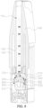
FIG. 4 is still another perspective view of a heating top cover and a heating body according to an embodiment of the present invention. -
FIG. 5 is a schematic diagram of a liquid return groove according to an embodiment of the present invention. -
FIG. 6 is another schematic diagram of a liquid return groove according to an embodiment of the present invention. -
FIG. 7 is a cross-sectional view of an atomizer showing a direction of gas during operation of the atomizer according to an embodiment of the present invention. -
FIG. 8 is a cross-sectional view of an atomizer showing a direction of condensate during operation of the atomizer according to an embodiment of the present invention. - To make the foregoing objects, features and advantages of the present invention more comprehensible, detailed description is made to specific embodiments of the present invention below with reference to the accompanying drawings. In the following description, many specific details are provided to facilitate a full understanding of the present invention. However, the present invention may alternatively be implemented in other manners different from those described herein, and a person skilled in the art may make similar modifications without departing from the content of the present invention. Therefore, the present invention is not limited to the embodiments disclosed below.
- In the description of the present invention, it should be understood that directions or location relationships indicated by terms "center", "longitudinal", " transversely ", "length", "width", "thickness", "upper", "lower", "front", "rear", "left", "right", "vertical", "horizontal", "top", "bottom", "inner", "outer", "clockwise", "counterclockwise" "axial direction", "radial direction" and "circumferential direction" are directions or location relationships shown based on the accompanying drawings, are merely used for the convenience of describing the present invention and simplifying the description, but are not used to indicate or imply that a device or an element needs to have a particular direction or be constructed and operated in a particular direction, and therefore, cannot be understood as a limitation to the present invention.
- In addition, the terms "first" and "second" are used merely for the purpose of description, and shall not be construed as indicating or implying relative importance or implying a number of indicated technical features. Therefore, features defining "first" and "second" can explicitly or implicitly include at least one of the features. In description of the present invention, "multiple" means at least two, such as two and three unless it is specifically defined otherwise.
- In the present invention, unless otherwise explicitly specified and defined, terms such as "mounted", "connected", "connection", and "fixed" should be understood in broad sense, for example, the connection may be a fixed connection, a detachable connection, or an integral connection; or the connection may be a mechanical connection or an electrical connection; or the connection may be a direct connection, an indirect connection through an intermediary, or internal communication between two elements or a mutual action relationship between two elements, unless otherwise specified explicitly. A person of ordinary skill in the art can understand specific meanings of the terms in the present invention according to specific situations.
- In the present invention, unless explicitly specified or limited otherwise, a first characteristic "on" or "under" a second characteristic may be the first characteristic in direct contact with the second characteristic, or the first characteristic in indirect contact with the second characteristic by using an intermediate medium. In addition, the first feature being located "above" the second feature may be the first feature being located directly above or obliquely above the second feature, or may simply indicate that the first feature is higher in level than the second feature.
- The first feature "under", "below" and "down" the second feature may be that the first feature is directly below or obliquely below the second feature, or simply indicates that a horizontal height of the first feature is less than that of the second feature.
- It should be noted that, when a component is referred to as "being fixed to" or "being provided on" another component, the component may be directly on the another component, or there may be an intermediate component. When a component is considered to be "connected to" another component, the component may be directly connected to the another component, or an intervening component may also be present. The terms "vertical", "horizontal", "upper", "down", "left", "right" and similar expressions used in this specification are only for purposes of illustration but not indicate a unique embodiment.
- An embodiment of the present invention provides an electronic atomizing device, including an atomizer and a power supply. The power supply is configured to supply power to the atomizer, so that the atomizer can heat floral, foliar, and herbal liquid to form gases through atomizing. The power supply can be selected in the related art.
- Referring to
FIG. 1 to FIG. 8 , the atomizer according to an embodiment of the present invention includes amain body 100, aheating top cover 200, and aheating body 300. Theheating top cover 200 and theheating body 300 are connected to each other and are provided in themain body 100. - The
main body 100 includes amain airway 110, and themain airway 110 is in communication with an external atmosphere. Themain airway 110 is configured to output atomizing gas after atomizing the liquid, and then guide the atomizing gas into the mouth of a user. In the embodiment shown inFIG. 1 andFIG. 4 , themain body 100 includes a hollowfirst housing 120 and a hollowsecond housing 130. Thefirst housing 120 is at least partially located inside thesecond housing 130. Optionally, thefirst housing 120 and thesecond housing 130 are integrally formed or may be a structure in which thefirst housing 120 and thesecond housing 130 are separately formed and then assembled into a whole. A hollow portion of thefirst housing 120 forms themain airway 110. Aliquid reservoir 140 for storing liquid is formed between thefirst housing 120 and thesecond housing 130. Aliquid outlet 141 is provided on a side of theliquid reservoir 140, and the liquid in theliquid reservoir 140 can flow out from theliquid outlet 141. - The
heating body 300 includes aheating surface 310, and a heating core absorbing liquid is provided on theheating surface 310. The heating core can be electrically connected to the power supply, so that when the power supply supplies power, the heating core generates heat and atomizes liquid that permeates into theheating surface 310. - The
heating top cover 200 includes a liquid passing channel 260 (shown inFIG. 7 ). A side of the liquid passingchannel 260 is provided with aliquid inlet 250 corresponding to theliquid outlet 141, so that the liquid can flow into theliquid inlet 250 along theliquid outlet 141 and enter theliquid passing channel 260. The other side of the liquid passingchannel 260 is in communication with a side of theheating body 300 away from theheating surface 310, so that the liquid can be in contact with theheating body 300. When the liquid is atomized, the liquid enters the liquid passingchannel 260 from theliquid reservoir 140 and enters theheating body 300, and then the liquid is atomized to form a gas under the heating of theheating surface 310 of theheating body 300. - As shown in
FIG. 1 , atop cover airway 210 is formed between the heatingtop cover 200 and an inner wall of themain body 100. Theheating top cover 200 includes anairway corner 220, and thetop cover airway 210 is in communication with themain airway 110 through theairway corner 220. In the illustrated embodiment, theheating top cover 200 can be U-shaped. A side of theheating top cover 200 can be provided with twoliquid inlets 250 that are spaced apart. Arecess 201 is formed in a middle portion of the side of theheating top cover 200 in a direction of approaching the heating body 300 (that is, a Z-axis direction showing inFIG. 1 ). A gap is formed between therecess 201 and themain body 100, so as to form theairway corner 220, and theairway corner 220 is in communication with themain airway 110. Thetop cover airway 210 can be formed between a side wall of theheating top cover 200 and thesecond housing 130 of themain body 100. The liquid (that is, condensate) formed through condensation of gas in thetop cover airway 210 can flow back to theairway corner 220. A shape and a structure of thetop cover airway 210 are not specifically limited, and can be configured according to actual conditions. - The liquid entering the liquid passing
channel 260 from theliquid reservoir 140 is atomized by the heating of theheating body 300, so that gas is obtained. As shown in arrows inFIG. 4 , the gas enters themain airway 110 through theairway corner 220 along thetop cover airway 210, and moves to the outside of themain body 100 for the user to inhale. In this process, a part of the atomized gas may be cooled down and liquefied during the movement, thus forming condensate. As shown by arrows inFIG. 5 , the condensate will return to theairway corner 220 along an inner wall of the main airway 110 (that is, an inner wall of the first housing 120). In a vertical direction (that is, the Z-axis direction inFIG. 1 to FIG. 5 ), since a height of therecess 201 of theheating top cover 200 is lower than a height of other parts of theheating top cover 200, the liquid will be accumulated at theairway corner 220. As the atomizer continuously performs atomizing, the accumulated liquid may be discharged from themain airway 110 as driven by an air flow during inhaling, causing liquid leakage, further resulting in poor reliability in resistance against the liquid leakage of the atomizer during inhaling. - In some embodiments, as shown in
FIG. 1 to FIG. 8 , aliquid return groove 230 extending to theheating body 300 is provided at theairway corner 220, so as to improve the reliability in resistance of the atomizer against liquid leakage during use. Theliquid return groove 230 can enable the liquid accumulated at theairway corner 220 to return to theheating body 300. Theliquid return groove 230 is located in therecess 201 of theheating top cover 200, and a side of theliquid return groove 230 is in communication with theheating body 300, so that the liquid can flow to theheating body 300 along theliquid return groove 230, as shown by arrows inFIG. 2 andFIG. 3 . The liquid on a surface of theheating body 300 can move into theheating body 300, and the liquid can be atomized again on the surface of theheating body 300 to form the gas. It should be understood that theheating body 300 can be made of a material such as porous ceramic or porous metal, but is not limited hereto, as long as it can implement secondary atomizing after the liquid comes into contact with the surface of theheating body 300. - For ease of description, a groove depth direction of the
liquid return groove 230 is defined as a depth direction (an X-axis direction inFIG. 1 to FIG. 4 ) of theliquid return groove 230. A direction of theliquid return groove 230 along theheating top cover 200 to theheating surface 310 of theheating body 300 is defined as a length direction (a Z-axis direction inFIG. 1 to FIG. 5 ) of theliquid return groove 230. A direction perpendicular to both the length direction and the depth direction is defined as a width direction (a Y-axis direction inFIG. 1 to FIG. 5 ) of theliquid return groove 230. - A shape and a size of the
liquid return groove 230 can both be adjusted according to actual conditions. In the illustrated embodiment, the shape of theliquid return groove 230 is cuboid or cuboid-like. - In some embodiments, the
liquid return groove 230 is provided on a side of theheating top cover 200 adjacent to theheating body 300. The surface of theheating body 300 can be exposed to theairway corner 220 from theliquid return groove 230. - As shown in
FIG. 1 to FIG. 8 , theliquid return groove 230 is formed by enclosing abottom wall 231 and side walls. - The bottom wall 231 (shown in
FIG. 6 to FIG. 8 ) is located on a side of theliquid return groove 230 along a depth direction and adjacent to the heating body. Thebottom wall 231 of theliquid return groove 230 penetrates through theheating top cover 200, so that theliquid return groove 230 forms a through hole in the X-axis direction. - As shown in
FIG. 5 andFIG. 6 , the side walls may include afirst side wall 233, asecond side wall 234, athird side wall 235, and afourth side wall 236 that are connected end to end. Thefirst side wall 233 and thethird side wall 235 are provided opposite to each other in the length direction (Z-axis direction) of theliquid return groove 230. Thefirst side wall 233 is located on a side that is away from theheating surface 310. Thethird side wall 235 is located on a side adjacent to theheating surface 310. Thesecond side wall 234 and thefourth side wall 236 are provided opposite to each other in the width direction (Y-axis direction) of theliquid return groove 230. - In some embodiments, as shown in
FIG. 1 to FIG. 3 , theliquid return groove 230 includes a side wall opening 232, which is used for liquid to pass through. - For example, in some embodiments, the
third side wall 235 of theliquid return groove 230 is provided with at least one side wall opening 232, and the liquid can flow in the length direction (Z-axis direction) of theliquid return groove 230 to flow to theheating body 300 for secondary atomizing. The liquid can also move in the depth direction (X-axis direction) of theliquid return groove 230, so as to be adsorbed by the surface of theheating body 300 for secondary atomizing. - In some other embodiments, at least one of the
second side wall 234 and thefourth side wall 236, and thethird side wall 235 are both provided with theside wall openings 232. The liquid can flow to the surface of theheating body 300 along any one of theside wall openings 232 for secondary atomizing. - As shown in
FIG. 4 , in some other embodiments, the side walls of theliquid return groove 230 are not all provided with a side wall opening. The liquid moves in the depth direction (X-axis direction) of theliquid return groove 230, so as to be adsorbed to the surface of theheating body 300 for secondary atomizing. - In some embodiments, as shown in
FIG. 6 , at least one side wall of theliquid return groove 230 is provided with aninclined surface 237. Theinclined surface 237 can guide the liquid to flow to theheating body 300. Theinclined surface 237 gradually approaches theheating body 300 in a moving direction of the liquid. That is, theinclined surface 237 gradually approaches theheating body 300 in a direction from the side wall to a middle portion of theliquid return groove 230. An inclination angle of theinclined surface 237 can be adjusted according to actual conditions. - For example, in some embodiments, the side wall of the
liquid return groove 230 along the length direction of theliquid return groove 230 and away from theheating surface 310 is provided with theinclined surface 237. That is, thefirst side wall 233 of theliquid return groove 230 is provided with theinclined surface 237. Theinclined surface 237 gradually approaches theheating body 300 in a direction from thefirst side wall 233 to thethird side wall 235. The liquid can flow through theliquid return groove 230 along theinclined surface 237 provided on thefirst side wall 233 and flow to the surface of theheating body 300. - In another example, in some other embodiments, the
first side wall 233, thesecond side wall 234, and thefourth side wall 236 of theliquid return groove 230 are all provided withinclined surfaces 237 to facilitate the liquid to flow into theliquid return groove 230. - In some embodiments, in the length direction of the
liquid return groove 230, a thickness of the side wall of theliquid return groove 230 gradually decreases. In some other embodiments, in the length direction of theliquid return groove 230, a thickness of the side wall of theliquid return groove 230 remains unchanged. - In some embodiments, in the depth direction of the
liquid return groove 230, thebottom wall 231 of theliquid return groove 230 abuts against theheating body 300. - In some other embodiments, a gap is formed between the
bottom wall 231 of theliquid return groove 230 and the side wall of theheating body 300. It should be noted that a width of the gap in the depth direction of theliquid return groove 230 cannot be too large, and needs to satisfy that the surface of the liquid flowing to thegroove bottom wall 231 of theliquid return groove 230 can come into contact with the surface of theheating body 300, to facilitate secondary atomizing of the liquid. - For ease of description, a total width of the
heating top cover 200 in the width direction of theliquid return groove 230 is defined as D. A portion of theheating top cover 200 located in a range of from 0.25D to 0.75D (including end points) is defined as a middle portion of theheating top cover 200. A portion of theheating top cover 200 that is located in a range of from 0 to 0.25D (excluding end points) or from 0.75D to D (excluding end points) is defined as an edge of theheating top cover 200. - One or more
liquid return grooves 230 can be provided. For example, in some embodiments, there is only oneliquid return groove 230 located in the middle portion of theheating top cover 200 in the width direction of theliquid return groove 230. - In another example, in some other embodiments, there are two or more
liquid return grooves 230, and theliquid return grooves 230 are spaced apart on theheating top cover 200. In some embodiments, all of theliquid return grooves 230 are spaced apart in the width direction of theliquid return grooves 230, and gaps between adjacentliquid return grooves 230 have the same or different widths. For example, in some embodiments, theliquid return grooves 230 are equally spaced apart. - In another example, in some embodiments, a plurality of
liquid return grooves 230 are provided, and in the width direction of theliquid return grooves 230, the number ofliquid return grooves 230 that are located in the middle portion of theheating top cover 200 is M (M is a positive integer). The number ofliquid return grooves 230 that are located at an edge of theheating top cover 200 is N (N is a positive integer), and M is greater than or equal to N. - In some embodiments, the
liquid return grooves 230 can be arranged in one or more rows in the length direction of theliquid return grooves 230, and each row includes a plurality ofliquid return grooves 230. For example, in an embodiment shown in the figure, theliquid return grooves 230 are arranged in one row. - In another example, in other embodiments, the
liquid return grooves 230 may be arranged in a plurality of rows, and intervals between adjacent rows may be the same or different. In addition, theliquid return grooves 230 in each row may not be located at the same horizontal plane. In addition, theliquid return grooves 230 may have the same or different lengths and widths. For example, in some embodiments, all of theliquid return grooves 230 have the same length and the same width and are equally spaced apart. - In another example, in an embodiment, none of the
liquid return grooves 230 have the same length and the same width, and theliquid return grooves 230 are equally spaced apart. In addition, in the width direction of theliquid return grooves 230, a width of theliquid return groove 230 located in the middle portion of theheating top cover 200 is greater than a width of theliquid return groove 230 located at the edge of theheating top cover 200, and a length of theliquid return groove 230 located in the middle portion of theheating top cover 200 is less than a length of theliquid return groove 230 located at the edge of theheating top cover 200. - In another example, in an embodiment, none of the
liquid return grooves 230 have the same length, but all of theliquid return grooves 230 have the same width, and theliquid return grooves 230 are equally spaced apart. In addition, in the width direction of theliquid return grooves 230, a length of theliquid return groove 230 located in the middle portion of theheating top cover 200 is less than a length of theliquid return groove 230 located at the edge of theheating top cover 200. - It should be noted that regardless how the length of the
liquid return groove 230 is configured, groove bottoms of all theliquid return grooves 230 completely or partially expose the side wall of theheating body 300. That is, theliquid return groove 230 is configured for the liquid to return to theheating body 300 from theairway corner 220. - In an embodiment, the
liquid return grooves 230 may be provided on two opposite side walls of theheating top cover 200 in the depth direction of theliquid return grooves 230. In some other embodiments, theliquid return grooves 230 may only be provided on a specific side wall of theheating top cover 200. - As shown in
FIG. 1 ,FIG. 2 ,FIG. 6 , andFIG. 7 , theheating top cover 200 is provided with aliquid guide groove 240. A side of theliquid guide groove 240 is located at therecess 201 or adjacent to therecess 201, and the other side of theliquid guide groove 240 is located on a side of theheating top cover 200 adjacent to theheating surface 310. The side wall of theliquid guide groove 240 may partially protrude from an outer surface of theheating top cover 200, or may be coplanar with the outer surface of theheating top cover 200. - For example, in the illustrated embodiment, a
convex bar 241 is provided on theheating top cover 200. Theconvex bar 241 is arranged in the length direction of theliquid return groove 230. In other embodiments, a plurality ofconvex bars 241 are provided, and the plurality ofconvex bars 241 are spaced apart. Theliquid guide groove 240 is formed between adjacentconvex bars 241. - As shown in arrows in
FIG. 2 , theliquid guide groove 240 is in communication with theliquid return groove 230, so that the liquid accumulated at theairway corner 220 can flow along theliquid guide groove 240 to theliquid return groove 230, and then enter theheating body 300. In addition, the arrangement of theliquid guide groove 240 enables the liquid to flow to theliquid return groove 230 along a specific path in a relatively concentrated manner. That is, under the action of theliquid guide groove 240, a large amount of the liquid flows along theliquid guide groove 240 to theliquid return groove 230 for secondary atomizing. However, a small amount of the liquid may flow to theheating body 300 along a portion of theheating top cover 200 on which noliquid guide groove 240 is provided. - In some of the embodiments, a side of the
liquid guide groove 240 away from themain airway 110 is in communication with theliquid return groove 230. In some other embodiments, a middle portion of theliquid guide groove 240 is in communication with theliquid return groove 230. The position of theliquid return groove 230 relative to theliquid guide groove 240 can be adjusted according to actual conditions. - As shown in
FIG. 2 to FIG. 7 , in some embodiments, a protrudingportion 270 may further provided on therecess 201 of theheating top cover 200, and the protrudingportion 270 and theheating top cover 200 can be integrally formed or be connected in other manners. The protrudingportion 270 extends in a direction of themain airway 110. Aflange 271 may be provided at a joint between the protrudingportion 270 and therecess 201 of theheating top cover 200, and a surface of theflange 271 may be an inclined flat surface or an inclined curved surface, so that the liquid flows from therecess 201 along the surface of theflange 271 to theliquid return groove 230. The arrangement of the protrudingportion 270 can reduce a depth of therecess 201 without affecting ventilation of theairway corner 220, so as to reduce a maximum amount of the accumulated liquid. - In the present invention, the
liquid return groove 230 is provided on theheating top cover 200, so that the liquid accumulated at theairway corner 220 can return to theheating body 300 in the depth direction of theliquid return groove 230 for secondary atomizing. In addition, the foregoing arrangement can prevent the liquid from leaking out of the atomizer from themain airway 110, thereby effectively improving liquid leakage-proof ability of the atomizer and the electronic atomizing device during using. - The technical features in the above embodiments may be randomly combined. For concise description, not all possible combinations of the technical features in the embodiment are described. However, provided that combinations of the technical features do not conflict with each other, the combinations of the technical features are considered as falling within the scope recorded in this specification.
- The foregoing embodiments only describe several embodiments of the present invention, and their description is specific and detailed, but cannot therefore be understood as a limitation to the patent scope of the present invention. It should be noted that for a person of ordinary skill in the art, several transformations and improvements can be made without departing from the creative idea of the present invention. These transformations and improvements belong to the protection scope of the present invention. Therefore, the protection scope of the present invention is subject to the protection scope of the appended claims.
Claims (10)
- An atomizer, comprising a heating top cover and a heating body, wherein the heating top cover comprises an airway corner, and a liquid return groove extending from the heating top cover to the heating body is provided at the airway corner.
- The atomizer according to claim 1, wherein the atomizer comprises a main body, the main body comprises a main airway, the heating top cover is provided in the main body, a top cover airway is formed between the heating top cover and the main body, and the top cover airway is in communication with the main airway through the airway corner.
- The atomizer according to claim 1, wherein a side wall of the liquid return groove adjacent to an atomizing surface of the heating body is provided with a side wall opening, and the side wall opening is configured to allow liquid to pass through.
- The atomizer according to claim 1, wherein at least one side wall of the liquid return groove is provided with an inclined surface, and the inclined surface is configured to guide liquid to flow to the heating body.
- The atomizer according to claim 4, wherein at least a part of the heating body is accommodated in the liquid return groove, and the inclined surface gradually approaches the heating body in a direction away from a bottom wall of the liquid return groove.
- The atomizer according to claim 1, wherein the heating top cover is provided with a liquid guide groove in communication with the liquid return groove, and the liquid guide groove is configured to guide liquid to flow to the liquid return groove.
- The atomizer according to claim 6, wherein one end of the liquid guide groove is located at the airway corner, and the other end of the liquid guide groove is located on a side of the heating top cover adjacent to an atomizing surface of the heating body.
- The atomizer according to claim 1, wherein a plurality of liquid return grooves are spaced apart at the airway corner.
- The atomizer according to any one of claims 1 to 8, wherein a number of liquid return grooves located in a middle portion of the heating top cover is M, and a number of liquid return grooves located at an edge of the heating top cover is N, and M is greater than or equal to N.
- An electronic atomizing device, comprising a power supply assembly and the atomizer according to any one of claims 1 to 9, wherein the power supply assembly is electrically connected to the heating body of the atomizer.
Applications Claiming Priority (1)
| Application Number | Priority Date | Filing Date | Title |
|---|---|---|---|
| CN202122399160.6U CN216674702U (en) | 2021-09-30 | 2021-09-30 | Atomizer and electronic atomization device |
Publications (1)
| Publication Number | Publication Date |
|---|---|
| EP4166015A1 true EP4166015A1 (en) | 2023-04-19 |
Family
ID=81831118
Family Applications (1)
| Application Number | Title | Priority Date | Filing Date |
|---|---|---|---|
| EP22198369.5A Pending EP4166015A1 (en) | 2021-09-30 | 2022-09-28 | Electronic atomizing device and atomizer thereof |
Country Status (5)
| Country | Link |
|---|---|
| US (1) | US20230097171A1 (en) |
| EP (1) | EP4166015A1 (en) |
| JP (1) | JP7414910B2 (en) |
| KR (1) | KR20230046954A (en) |
| CN (1) | CN216674702U (en) |
Citations (5)
| Publication number | Priority date | Publication date | Assignee | Title |
|---|---|---|---|---|
| WO2020081849A2 (en) * | 2018-10-17 | 2020-04-23 | Juul Labs, Inc. | Cartridge for a vaporizer device |
| CN112545064A (en) * | 2020-12-18 | 2021-03-26 | 深圳麦克韦尔科技有限公司 | Atomizer and electronic atomization device |
| WO2021062779A1 (en) * | 2019-09-30 | 2021-04-08 | 深圳麦克韦尔科技有限公司 | Electronic vaporization device and vaporizer thereof |
| CN113017152A (en) * | 2021-03-04 | 2021-06-25 | 深圳麦克韦尔科技有限公司 | Atomizer and electronic atomization device thereof |
| CN113100485A (en) * | 2021-04-28 | 2021-07-13 | 深圳市赛尔美电子科技有限公司 | Atomization assembly and atomization device with same |
-
2021
- 2021-09-30 CN CN202122399160.6U patent/CN216674702U/en active Active
-
2022
- 2022-08-09 JP JP2022127213A patent/JP7414910B2/en active Active
- 2022-08-19 KR KR1020220103870A patent/KR20230046954A/en unknown
- 2022-09-20 US US17/933,605 patent/US20230097171A1/en active Pending
- 2022-09-28 EP EP22198369.5A patent/EP4166015A1/en active Pending
Patent Citations (5)
| Publication number | Priority date | Publication date | Assignee | Title |
|---|---|---|---|---|
| WO2020081849A2 (en) * | 2018-10-17 | 2020-04-23 | Juul Labs, Inc. | Cartridge for a vaporizer device |
| WO2021062779A1 (en) * | 2019-09-30 | 2021-04-08 | 深圳麦克韦尔科技有限公司 | Electronic vaporization device and vaporizer thereof |
| CN112545064A (en) * | 2020-12-18 | 2021-03-26 | 深圳麦克韦尔科技有限公司 | Atomizer and electronic atomization device |
| CN113017152A (en) * | 2021-03-04 | 2021-06-25 | 深圳麦克韦尔科技有限公司 | Atomizer and electronic atomization device thereof |
| CN113100485A (en) * | 2021-04-28 | 2021-07-13 | 深圳市赛尔美电子科技有限公司 | Atomization assembly and atomization device with same |
Also Published As
| Publication number | Publication date |
|---|---|
| US20230097171A1 (en) | 2023-03-30 |
| KR20230046954A (en) | 2023-04-06 |
| CN216674702U (en) | 2022-06-07 |
| JP2023051754A (en) | 2023-04-11 |
| JP7414910B2 (en) | 2024-01-16 |
Similar Documents
| Publication | Publication Date | Title |
|---|---|---|
| CN215075497U (en) | Atomizer and electronic atomization device | |
| CN108308716B (en) | Electronic cigarette and heating assembly thereof | |
| US11284645B2 (en) | Vaporization device | |
| EP4268635A1 (en) | Electronic atomization device, and atomizer and atomization assembly thereof | |
| CN113100485A (en) | Atomization assembly and atomization device with same | |
| CN113892696A (en) | Atomizer and electronic atomization device | |
| CN114304744A (en) | Cooling atomizer and aerosol generating device | |
| CN111109678A (en) | Electronic atomization device and atomizer and atomization assembly thereof | |
| EP4166015A1 (en) | Electronic atomizing device and atomizer thereof | |
| CN217161079U (en) | Atomizing footstock, atomizer and electronic atomization device | |
| WO2023155476A1 (en) | Atomizer and atomization device | |
| CN217826745U (en) | Electronic atomization device and atomizer thereof | |
| CN216135183U (en) | Atomization assembly, atomizer and electronic atomization device | |
| CN217509876U (en) | Atomizer and electronic atomization device | |
| CN214854326U (en) | Electronic atomization device and atomizer and atomization assembly thereof | |
| WO2022024894A1 (en) | Battery pack and battery case | |
| CN215347019U (en) | Atomizer and aerosol generating device | |
| CN219741844U (en) | Shell assembly and electronic atomization device | |
| CN218898364U (en) | Heating component, atomizer and electronic atomization device | |
| CN217958741U (en) | Electronic atomization device and atomizer and ventilation structure thereof | |
| EP4205575A1 (en) | Vaporization assembly and electronic vaporization device | |
| EP4194037A1 (en) | Atomizer and electronic atomizing device | |
| CN219422188U (en) | Atomizing device and atomizing equipment | |
| CN219679773U (en) | Atomizing device and electronic atomizer | |
| CN218889285U (en) | Atomizing core and atomizer |
Legal Events
| Date | Code | Title | Description |
|---|---|---|---|
| PUAI | Public reference made under article 153(3) epc to a published international application that has entered the european phase |
Free format text: ORIGINAL CODE: 0009012 |
|
| STAA | Information on the status of an ep patent application or granted ep patent |
Free format text: STATUS: THE APPLICATION HAS BEEN PUBLISHED |
|
| AK | Designated contracting states |
Kind code of ref document: A1 Designated state(s): AL AT BE BG CH CY CZ DE DK EE ES FI FR GB GR HR HU IE IS IT LI LT LU LV MC MK MT NL NO PL PT RO RS SE SI SK SM TR |
|
| STAA | Information on the status of an ep patent application or granted ep patent |
Free format text: STATUS: REQUEST FOR EXAMINATION WAS MADE |
|
| 17P | Request for examination filed |
Effective date: 20230914 |
|
| RBV | Designated contracting states (corrected) |
Designated state(s): AL AT BE BG CH CY CZ DE DK EE ES FI FR GB GR HR HU IE IS IT LI LT LU LV MC MK MT NL NO PL PT RO RS SE SI SK SM TR |