EP4165665B1 - Integrierte isolatordichtung und abschirmungsanordnungen - Google Patents
Integrierte isolatordichtung und abschirmungsanordnungen Download PDFInfo
- Publication number
- EP4165665B1 EP4165665B1 EP21821274.4A EP21821274A EP4165665B1 EP 4165665 B1 EP4165665 B1 EP 4165665B1 EP 21821274 A EP21821274 A EP 21821274A EP 4165665 B1 EP4165665 B1 EP 4165665B1
- Authority
- EP
- European Patent Office
- Prior art keywords
- seal
- counterbore
- sealing
- tapered end
- frustum
- Prior art date
- Legal status (The legal status is an assumption and is not a legal conclusion. Google has not performed a legal analysis and makes no representation as to the accuracy of the status listed.)
- Active
Links
Images


Classifications
-
- H—ELECTRICITY
- H01—ELECTRIC ELEMENTS
- H01B—CABLES; CONDUCTORS; INSULATORS; SELECTION OF MATERIALS FOR THEIR CONDUCTIVE, INSULATING OR DIELECTRIC PROPERTIES
- H01B17/00—Insulators or insulating bodies characterised by their form
- H01B17/38—Fittings, e.g. caps; Fastenings therefor
- H01B17/40—Cementless fittings
-
- H—ELECTRICITY
- H01—ELECTRIC ELEMENTS
- H01B—CABLES; CONDUCTORS; INSULATORS; SELECTION OF MATERIALS FOR THEIR CONDUCTIVE, INSULATING OR DIELECTRIC PROPERTIES
- H01B17/00—Insulators or insulating bodies characterised by their form
- H01B17/26—Lead-in insulators; Lead-through insulators
- H01B17/30—Sealing
- H01B17/303—Sealing of leads to lead-through insulators
- H01B17/308—Sealing of leads to lead-through insulators by compressing packing material
-
- H—ELECTRICITY
- H01—ELECTRIC ELEMENTS
- H01B—CABLES; CONDUCTORS; INSULATORS; SELECTION OF MATERIALS FOR THEIR CONDUCTIVE, INSULATING OR DIELECTRIC PROPERTIES
- H01B17/00—Insulators or insulating bodies characterised by their form
- H01B17/02—Suspension insulators; Strain insulators
- H01B17/06—Fastening of insulator to support, to conductor, or to adjoining insulator
-
- H—ELECTRICITY
- H01—ELECTRIC ELEMENTS
- H01B—CABLES; CONDUCTORS; INSULATORS; SELECTION OF MATERIALS FOR THEIR CONDUCTIVE, INSULATING OR DIELECTRIC PROPERTIES
- H01B17/00—Insulators or insulating bodies characterised by their form
- H01B17/26—Lead-in insulators; Lead-through insulators
- H01B17/30—Sealing
-
- H—ELECTRICITY
- H01—ELECTRIC ELEMENTS
- H01B—CABLES; CONDUCTORS; INSULATORS; SELECTION OF MATERIALS FOR THEIR CONDUCTIVE, INSULATING OR DIELECTRIC PROPERTIES
- H01B17/00—Insulators or insulating bodies characterised by their form
- H01B17/42—Means for obtaining improved distribution of voltage; Protection against arc discharges
- H01B17/44—Structural association of insulators with corona rings
-
- H—ELECTRICITY
- H01—ELECTRIC ELEMENTS
- H01B—CABLES; CONDUCTORS; INSULATORS; SELECTION OF MATERIALS FOR THEIR CONDUCTIVE, INSULATING OR DIELECTRIC PROPERTIES
- H01B17/00—Insulators or insulating bodies characterised by their form
- H01B17/56—Insulating bodies
- H01B17/58—Tubes, sleeves, beads, or bobbins through which the conductor passes
-
- H—ELECTRICITY
- H02—GENERATION; CONVERSION OR DISTRIBUTION OF ELECTRIC POWER
- H02G—INSTALLATION OF ELECTRIC CABLES OR LINES, OR OF COMBINED OPTICAL AND ELECTRIC CABLES OR LINES
- H02G15/00—Cable fittings
- H02G15/013—Sealing means for cable inlets
Definitions
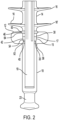
- Electrical polymer insulators are used in power transmission and distribution systems to provide mechanical support for conductors and provide electrical insulation between the high voltage conductors and grounded tower structures.
- a corona protection device is located at the line end and/or the ground end of the insulator and eliminates the corona discharge from the insulator. Elimination of the corona discharge protects the surface of the insulator from polymeric material deterioration caused by electrical stress. Additionally, eliminating the corona discharge reduces television and/or radio noise created by the corona discharge.
- US 2009/095506 A1 discloses an integrated insulator seal and shield assembly.
- US 5914462 A discloses a composite insulator having end fittings with gaps.
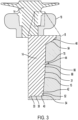
- the present disclosure further provides the insulator sealing and shielding assembly with a rubber housing tapered into a metal fitting to increase the compression connection therebetween.
- the present disclosure still further provides the insulator sealing and shielding assembly with a plurality of radial weathersheds disposed along an exterior of the housing and the endmost weathershed adjacent to the collar assembly connected to the hardware.
- an insulator sealing and shielding assembly having a rubber housing with a plurality of weathersheds and a tapered end adjacent the metal fitting.
- Four sealing surfaces between the counterbore of the collar assembly and the rubber housing secure the connection therebetween creating an integral metal fitting and rubber housing.
- the sealing surface is a flat surface on the counterbore of the metal end fitting.
- the ring protrudes from the tapered end so that the ring applies a compressive sealing force against the flat surface.
- the seal formed by the ring and the sealing surface is positioned on the tapered end of the rubber housing between the sealing surface formed by the raised rib that abuts the outer portion of the counterbore and another sealing surface that is a radial compression seal located between a first frustum of the rubber housing and a second frustum of said counterbore.
- the first seal is adjacent the second seal on a side that is opposite the third seal.
- Second seal 42 is located slightly above first seal 40.
- Second seal 42 is a radial compression seal created by pushing a first frustum 52 of the rubber housing 14 into a second frustum 54 of counterbore 15 imparting increasing compressing force between rubber housing 14 and the counterbore 15.
- first frustum 52 has a first angle 53 that tapered end 30 forms with a line 55 that is parallel with a center axis A.
- second frustum 54 has a second angle 57 formed by a line 59 parallel with center axis C and counterbore 15.
- First angle 53 is smaller than second angle 57 to create the increasing compressing force between rubber housing 14 and the counterbore 15 to form a radial compression seal located between first frustum 52 of rubber housing 14 and second frustum 54 of counterbore 15.
- fourth seal 46 is located towards the top of collar assembly 12 at the junction of the rubber housing 14 and an outer portion 64 of the counterbore 15.
- Fourth seal 46 is the lip seal defined by the intersection of a raised rib 50 on rubber housing 14 and an outer portion of counterbore 15 to provide an initial seal against moisture ingress.
- Raised rib 50 is the lowermost extension of rubber housing 14 on the side of endmost weathershed 16' adjacent collar assembly 12.
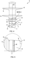
- Assembly 10 simplifies the manufacturability of metal end fitting 18 without the requirement of secondary operations such as cross drilling and reduces the assembly part count. Thus, assembly 10 optimizes the design, manufacturability, and quality of insulator sealing and shielding assemblies.
Landscapes
- Engineering & Computer Science (AREA)
- Power Engineering (AREA)
- Gasket Seals (AREA)
Claims (15)
- Integrierte Isolatordichtungs- und Abschirmungsanordnung (10), umfassend:ein Gummigehäuse (14), der eine Vielzahl von radialen Wetterschutzeinrichtungen (16) und ein verjüngtes Ende (30) angrenzend an eine äußerste radiale Wetterschutzeinrichtung (16) aufweist, wobei das verjüngte Ende (30) eine Außenfläche (31) mit einem Ring (66) aufweist, der sich von der Außenfläche (31) nach außen erstreckt, wobei der Ring (66) komprimierbar ist;ein Metallendstück (18), das angrenzend an die äußerste radiale Wetterschutzeinrichtung (16) angeordnet ist und das verjüngte Ende (30) aufnimmt, wobei das verjüngte Ende (30) in einer Senkbohrung (15) im Metallendstück (18) aufgenommen wird, wobei die Senkbohrung (15) eine Dichtfläche (68) aufweist, so dass eine Überlagerung des Rings (66) mit der Dichtfläche (68) eine Druckdichtungskraft erzeugt, um eine Dichtung zu bilden.
- Integrierte Isolatordichtungs- und Abschirmungsanordnung (10) nach Anspruch 1, wobei das Gummigehäuse (14) aus Gummi hergestellt ist.
- Integrierte Isolatordichtungs- und Abschirmungsanordnung (10) nach Anspruch 1, wobei die Dichtfläche (68) eine Nut (70) in der Senkbohrung (15) des Metallendstücks (18) aufweist, wobei die Nut (70) optional so bemessen ist, dass sie den Ring (66) aufnimmt, während der Ring (66) eine Druckdichtungskraft auf die Nut (70) ausübt.
- Integrierte Isolatordichtungs- und Abschirmungsanordnung (10) nach Anspruch 1, wobei die Dichtfläche (68) eine flache Oberfläche (72) auf der Senkbohrung (15) des Metallendstücks (18) ist, wobei der Ring (66) optional aus dem verjüngten Ende (30) vorspringt, so dass der Ring (66) eine kompressive Dichtungskraft auf die flache Oberfläche (72) ausübt.
- Integrierte Isolatordichtungs- und Abschirmungsanordnung (10) nach Anspruch 1, weiter umfassend mindestens eine Dichtfläche (68), die eine radiale Kompressionsdichtung ist, die zwischen einem ersten Kegelstumpf (52) des Gummigehäuses (14) und einem zweiten Kegelstumpf (54) der Senkbohrung (15) angeordnet ist.
- Integrierte Isolatordichtungs- und Abschirmungsanordnung (10) nach Anspruch 5, wobei das verjüngte Ende (30) ein Ende aufweist, das der äußersten radialen Wetterschutzeinrichtung (16) gegenüberliegt, und wobei ein Teil des verjüngten Endes (30) zwischen dem Ring (66) und dem Ende den ersten Kegelstumpf (52) bildet.
- Integrierte Isolatordichtungs- und Abschirmungsanordnung (10) nach Anspruch 6, wobei die Senkbohrung (15) den zweiten Kegelstumpf (54) bildet, um den ersten Kegelstumpf (52) des verjüngten Endes (30) aufzunehmen.
- Integrierte Isolatordichtungs- und Abschirmungsanordnung (10) nach Anspruch 7, wobei der erste Kegelstumpf (52) einen ersten Winkel aufweist, den das verjüngte Ende (30) mit einer Linie bildet, die parallel zu einer Mittelachse des Gummigehäuses (14) ist, und der zweite Kegelstumpf (54) einen zweiten Winkel aufweist, der durch eine Linie parallel zu einer Mittelachse des Metallgehäuses und der Senkbohrung (15) gebildet wird, wobei der erste Winkel optional kleiner als der zweite Winkel ist, um eine zunehmende Druckkraft zwischen dem Gummigehäuse (14) und der Senkbohrung (15) zu erzeugen.
- Integrierte Isolatordichtungs- und Abschirmungsanordnung (10) nach Anspruch 1, wobei das verjüngte Ende (30) ein Ende aufweist, das der äußersten radialen Wetterschutzeinrichtung (16) gegenüberliegt, und wobei die Senkbohrung (15) eine Dichtung bildet, die eine Verbindung zwischen einem Ende der Senkbohrung (15) und dem Ende des verjüngten Endes (30) darstellt.
- Integrierte Isolatordichtungs- und Abschirmungsanordnung (10) nach Anspruch 1, wobei das verjüngte Ende (30) eine erhabene Rippe (50) aufweist, die eine unterste Verlängerung des Gummigehäuses (14) auf einer Seite der äußersten Wetterschutzeinrichtung (16) neben dem Metallgehäuse ist.
- Integrierte Isolatordichtungs- und Abschirmungsanordnung (10) nach Anspruch 10, wobei die erhabene Rippe (50) an einem äußeren Abschnitt der Senkbohrung (15) anliegt, um eine Dichtfläche (68) zu bilden.
- Integrierte Isolatordichtungs- und Abschirmungsanordnung (10) nach Anspruch 11, wobei die durch den Ring (66) und die Dichtfläche (68) gebildete Dichtung auf dem verjüngten Ende (30) des Gummigehäuses (14) zwischen der durch die erhabene Rippe (50) gebildeten Dichtfläche (68), die an den äußeren Teil der Senkbohrung (15) angrenzt, und einer anderen Dichtfläche, die eine radiale Kompressionsdichtung ist, die sich zwischen einem ersten Kegelstumpf (52) des Gummigehäuses (14) und einem zweiten Kegelstumpf (54) der Senkbohrung (15) befindet, positioniert ist.
- Integrierte Isolatordichtungs- und Abschirmungsanordnung (10) nach Anspruch 12, wobei das verjüngte Ende (30) ein Ende aufweist, das der äußersten radialen Wetterschutzeinrichtung (16) gegenüberliegt, und wobei die Senkbohrung (15) eine Dichtung bildet, die die Verbindung zwischen einem Ende der Senkbohrung (15) und dem verjüngten Ende (30) des Gummigehäuses (14) darstellt.
- Integrierte Isolatordichtungs- und Abschirmungsanordnung (10) nach Anspruch 1, wobei die durch den Ring (66) und die Dichtfläche (68) gebildete Dichtung eine dritte Dichtung (44) ist, und weiter umfassend eine erste Dichtung (40), die durch eine Verbindung zwischen einem Ende der Senkbohrung (15) und dem verjüngten Ende (30) des Gummigehäuses (14) gebildet wird, eine zweite Dichtung (42), die eine radiale Kompressionsdichtung ist und sich zwischen einem ersten Kegelstumpf (52) des Gummigehäuses (14) und einem zweiten Kegelstumpf (54) der Senkbohrung (15) befindet, und eine vierte Dichtung (46), die eine erhabene Rippe (50) ist, die eine unterste Verlängerung des Gummigehäuses (14) auf einer Seite der äußersten Wetterschutzeinrichtung (16) neben dem Metallgehäuse ist, das an einem äußeren Teil der Senkbohrung (15) angrenzt.
- Integrierte Isolatordichtungs- und Abschirmungsanordnung (10) nach Anspruch 14, wobei die dritte Dichtung (44) zwischen der zweiten Dichtung (42) und der vierten Dichtung (46) liegt, wobei die erste Dichtung (40) optional an die zweite Dichtung (42) auf einer Seite angrenzt, die der dritten Dichtung (44) gegenüberliegt.
Applications Claiming Priority (2)
| Application Number | Priority Date | Filing Date | Title |
|---|---|---|---|
| US202063038357P | 2020-06-12 | 2020-06-12 | |
| PCT/US2021/036780 WO2021252743A1 (en) | 2020-06-12 | 2021-06-10 | Integrated insulator seal and shield assemblies |
Publications (3)
| Publication Number | Publication Date |
|---|---|
| EP4165665A1 EP4165665A1 (de) | 2023-04-19 |
| EP4165665A4 EP4165665A4 (de) | 2024-03-06 |
| EP4165665B1 true EP4165665B1 (de) | 2025-04-09 |
Family
ID=78826586
Family Applications (1)
| Application Number | Title | Priority Date | Filing Date |
|---|---|---|---|
| EP21821274.4A Active EP4165665B1 (de) | 2020-06-12 | 2021-06-10 | Integrierte isolatordichtung und abschirmungsanordnungen |
Country Status (4)
| Country | Link |
|---|---|
| US (1) | US11488748B2 (de) |
| EP (1) | EP4165665B1 (de) |
| CN (1) | CN115699226B (de) |
| WO (1) | WO2021252743A1 (de) |
Family Cites Families (17)
| Publication number | Priority date | Publication date | Assignee | Title |
|---|---|---|---|---|
| US2906809A (en) * | 1956-12-04 | 1959-09-29 | Koppers Co Inc | Coaxial cable termination |
| US3096392A (en) * | 1959-04-28 | 1963-07-02 | Porter Co Inc H K | Transformer bushing construction |
| US3652782A (en) * | 1969-08-04 | 1972-03-28 | Hisatomo Furusawa | Stress relief apparatus for cable connection |
| US5214249A (en) * | 1991-02-22 | 1993-05-25 | Hubbell Incorporated | Electrical assembly with end collars for coupling ends of a weathershed housing to the end fittings |
| SE501127C2 (sv) * | 1993-03-16 | 1994-11-21 | Asea Brown Boveri | Ventilavledare |
| JP2820380B2 (ja) | 1995-02-21 | 1998-11-05 | 日本碍子株式会社 | ポリマー碍子の製造方法 |
| CN2226334Y (zh) * | 1995-04-28 | 1996-05-01 | 黄小宁 | 高压合成绝缘子 |
| DE19629796C5 (de) * | 1996-07-24 | 2004-12-16 | Lapp Insulator Gmbh & Co. Kg | Kunststoffverbundisolator mit spiralförmigem Schirm und Verfahren zu seiner Herstellung |
| US6265669B1 (en) * | 1996-08-12 | 2001-07-24 | Clyde N. Richards | Semiconductive attachment disc for insulators to reduce electrical stress-induced corrosion |
| US6472604B2 (en) * | 2000-03-13 | 2002-10-29 | Ngk Insulators, Ltd. | Seal construction of polymer insulator |
| US6388197B1 (en) * | 2000-03-23 | 2002-05-14 | Hubbell Incorporated | Corona protection device of semiconductive rubber for polymer insulators |
| CN2632819Y (zh) * | 2003-06-25 | 2004-08-11 | 及荣军 | 具有圆锥形压缩式密封环的合成绝缘子 |
| US6984790B1 (en) * | 2005-04-27 | 2006-01-10 | Hubbell Incorporated | Insulator sealing and shielding collar assembly |
| US7709743B2 (en) * | 2007-10-15 | 2010-05-04 | Hubbell Incorporated | Integrated insulator seal and shield assemblies |
| US8653376B2 (en) * | 2009-08-04 | 2014-02-18 | Pfisterer Sefag Ag | Corona shield and composite insulator with corona shield |
| CN205050644U (zh) * | 2015-10-30 | 2016-02-24 | 大连电瓷集团股份有限公司 | 悬式复合绝缘子金具端部复合式密封结构 |
| CN210378617U (zh) * | 2019-10-18 | 2020-04-21 | 萍乡市浩洋电瓷制造有限公司 | 一种组装式绝缘子 |
-
2021
- 2021-06-10 WO PCT/US2021/036780 patent/WO2021252743A1/en not_active Ceased
- 2021-06-10 CN CN202180042178.0A patent/CN115699226B/zh active Active
- 2021-06-10 EP EP21821274.4A patent/EP4165665B1/de active Active
- 2021-06-10 US US17/344,344 patent/US11488748B2/en active Active
Also Published As
| Publication number | Publication date |
|---|---|
| US11488748B2 (en) | 2022-11-01 |
| WO2021252743A1 (en) | 2021-12-16 |
| EP4165665A1 (de) | 2023-04-19 |
| US20210391102A1 (en) | 2021-12-16 |
| CN115699226A (zh) | 2023-02-03 |
| EP4165665A4 (de) | 2024-03-06 |
| CN115699226B (zh) | 2025-09-09 |
Similar Documents
| Publication | Publication Date | Title |
|---|---|---|
| US7845980B1 (en) | Connector with integral seal | |
| US7255598B2 (en) | Coaxial cable compression connector | |
| CN105071067B (zh) | 提供同轴电缆连接器的连续电接地的弹性o型环 | |
| US7753705B2 (en) | Flexible RF seal for coaxial cable connector | |
| US6840803B2 (en) | Crimp connector for corrugated cable | |
| US9608343B2 (en) | Coaxial cable and connector with capacitive coupling | |
| CA2818333C (en) | Electrically conductive bushing connection to structure for current path | |
| EP2201580B1 (de) | Integrierte isolierdichtung und abschirmungsanordnungen | |
| CN102971921A (zh) | 抑制进入和改善接地的同轴连接器 | |
| US10844982B2 (en) | Adapter for sealing boot for electrical interconnections | |
| EP4165665B1 (de) | Integrierte isolatordichtung und abschirmungsanordnungen | |
| US20150118897A1 (en) | Coaxial cable and connector with capacitive coupling | |
| US6388197B1 (en) | Corona protection device of semiconductive rubber for polymer insulators | |
| EP3061162B1 (de) | Koaxialkabel und verbinder mit kapazitiver kopplung | |
| DE102017209368A1 (de) | Kabeldurchführung mit abschirmenden und abdichtenden Eigenschaften | |
| JP2008312373A (ja) | 電気機器の通電部材およびこれを用いた電気機器の接続部 | |
| US6984790B1 (en) | Insulator sealing and shielding collar assembly | |
| AU2023208098B2 (en) | Assemblies for mitigating dry band arcing on power distribution line insulators | |
| US12498074B2 (en) | Composite fluid transfer conduit | |
| US12512654B2 (en) | Cable gland | |
| EP3534465B1 (de) | Abschirmanordnung | |
| US20240072524A1 (en) | Cable gland | |
| JPH09266621A (ja) | プレハブジョイントによる接続箱 |
Legal Events
| Date | Code | Title | Description |
|---|---|---|---|
| STAA | Information on the status of an ep patent application or granted ep patent |
Free format text: STATUS: THE INTERNATIONAL PUBLICATION HAS BEEN MADE |
|
| PUAI | Public reference made under article 153(3) epc to a published international application that has entered the european phase |
Free format text: ORIGINAL CODE: 0009012 |
|
| STAA | Information on the status of an ep patent application or granted ep patent |
Free format text: STATUS: REQUEST FOR EXAMINATION WAS MADE |
|
| 17P | Request for examination filed |
Effective date: 20221207 |
|
| AK | Designated contracting states |
Kind code of ref document: A1 Designated state(s): AL AT BE BG CH CY CZ DE DK EE ES FI FR GB GR HR HU IE IS IT LI LT LU LV MC MK MT NL NO PL PT RO RS SE SI SK SM TR |
|
| P01 | Opt-out of the competence of the unified patent court (upc) registered |
Effective date: 20230530 |
|
| DAV | Request for validation of the european patent (deleted) | ||
| DAX | Request for extension of the european patent (deleted) | ||
| A4 | Supplementary search report drawn up and despatched |
Effective date: 20240205 |
|
| RIC1 | Information provided on ipc code assigned before grant |
Ipc: H02G 15/013 20060101ALI20240130BHEP Ipc: H01B 17/06 20060101ALI20240130BHEP Ipc: H01B 17/56 20060101ALI20240130BHEP Ipc: H01B 17/48 20060101ALI20240130BHEP Ipc: H01B 17/46 20060101ALI20240130BHEP Ipc: H01B 17/44 20060101ALI20240130BHEP Ipc: H01B 17/00 20060101ALI20240130BHEP Ipc: H01B 17/42 20060101AFI20240130BHEP |
|
| GRAP | Despatch of communication of intention to grant a patent |
Free format text: ORIGINAL CODE: EPIDOSNIGR1 |
|
| STAA | Information on the status of an ep patent application or granted ep patent |
Free format text: STATUS: GRANT OF PATENT IS INTENDED |
|
| INTG | Intention to grant announced |
Effective date: 20241118 |
|
| GRAS | Grant fee paid |
Free format text: ORIGINAL CODE: EPIDOSNIGR3 |
|
| GRAA | (expected) grant |
Free format text: ORIGINAL CODE: 0009210 |
|
| STAA | Information on the status of an ep patent application or granted ep patent |
Free format text: STATUS: THE PATENT HAS BEEN GRANTED |
|
| AK | Designated contracting states |
Kind code of ref document: B1 Designated state(s): AL AT BE BG CH CY CZ DE DK EE ES FI FR GB GR HR HU IE IS IT LI LT LU LV MC MK MT NL NO PL PT RO RS SE SI SK SM TR |
|
| REG | Reference to a national code |
Ref country code: GB Ref legal event code: FG4D |
|
| REG | Reference to a national code |
Ref country code: CH Ref legal event code: EP |
|
| REG | Reference to a national code |
Ref country code: DE Ref legal event code: R096 Ref document number: 602021029019 Country of ref document: DE |
|
| REG | Reference to a national code |
Ref country code: IE Ref legal event code: FG4D |
|
| PGFP | Annual fee paid to national office [announced via postgrant information from national office to epo] |
Ref country code: DE Payment date: 20250627 Year of fee payment: 5 |
|
| PGFP | Annual fee paid to national office [announced via postgrant information from national office to epo] |
Ref country code: GB Payment date: 20250627 Year of fee payment: 5 |
|
| PGFP | Annual fee paid to national office [announced via postgrant information from national office to epo] |
Ref country code: FR Payment date: 20250625 Year of fee payment: 5 |
|
| PGFP | Annual fee paid to national office [announced via postgrant information from national office to epo] |
Ref country code: AT Payment date: 20250721 Year of fee payment: 5 |
|
| REG | Reference to a national code |
Ref country code: NL Ref legal event code: MP Effective date: 20250409 |
|
| PG25 | Lapsed in a contracting state [announced via postgrant information from national office to epo] |
Ref country code: NL Free format text: LAPSE BECAUSE OF FAILURE TO SUBMIT A TRANSLATION OF THE DESCRIPTION OR TO PAY THE FEE WITHIN THE PRESCRIBED TIME-LIMIT Effective date: 20250409 |
|
| REG | Reference to a national code |
Ref country code: AT Ref legal event code: MK05 Ref document number: 1784333 Country of ref document: AT Kind code of ref document: T Effective date: 20250409 |
|
| PG25 | Lapsed in a contracting state [announced via postgrant information from national office to epo] |
Ref country code: FI Free format text: LAPSE BECAUSE OF FAILURE TO SUBMIT A TRANSLATION OF THE DESCRIPTION OR TO PAY THE FEE WITHIN THE PRESCRIBED TIME-LIMIT Effective date: 20250409 Ref country code: PT Free format text: LAPSE BECAUSE OF FAILURE TO SUBMIT A TRANSLATION OF THE DESCRIPTION OR TO PAY THE FEE WITHIN THE PRESCRIBED TIME-LIMIT Effective date: 20250811 Ref country code: ES Free format text: LAPSE BECAUSE OF FAILURE TO SUBMIT A TRANSLATION OF THE DESCRIPTION OR TO PAY THE FEE WITHIN THE PRESCRIBED TIME-LIMIT Effective date: 20250409 |
|
| REG | Reference to a national code |
Ref country code: LT Ref legal event code: MG9D |
|
| PG25 | Lapsed in a contracting state [announced via postgrant information from national office to epo] |
Ref country code: GR Free format text: LAPSE BECAUSE OF FAILURE TO SUBMIT A TRANSLATION OF THE DESCRIPTION OR TO PAY THE FEE WITHIN THE PRESCRIBED TIME-LIMIT Effective date: 20250710 Ref country code: NO Free format text: LAPSE BECAUSE OF FAILURE TO SUBMIT A TRANSLATION OF THE DESCRIPTION OR TO PAY THE FEE WITHIN THE PRESCRIBED TIME-LIMIT Effective date: 20250709 |
|
| PG25 | Lapsed in a contracting state [announced via postgrant information from national office to epo] |
Ref country code: PL Free format text: LAPSE BECAUSE OF FAILURE TO SUBMIT A TRANSLATION OF THE DESCRIPTION OR TO PAY THE FEE WITHIN THE PRESCRIBED TIME-LIMIT Effective date: 20250409 |
|
| PG25 | Lapsed in a contracting state [announced via postgrant information from national office to epo] |
Ref country code: BG Free format text: LAPSE BECAUSE OF FAILURE TO SUBMIT A TRANSLATION OF THE DESCRIPTION OR TO PAY THE FEE WITHIN THE PRESCRIBED TIME-LIMIT Effective date: 20250409 |
|
| PG25 | Lapsed in a contracting state [announced via postgrant information from national office to epo] |
Ref country code: HR Free format text: LAPSE BECAUSE OF FAILURE TO SUBMIT A TRANSLATION OF THE DESCRIPTION OR TO PAY THE FEE WITHIN THE PRESCRIBED TIME-LIMIT Effective date: 20250409 |
|
| PG25 | Lapsed in a contracting state [announced via postgrant information from national office to epo] |
Ref country code: AT Free format text: LAPSE BECAUSE OF FAILURE TO SUBMIT A TRANSLATION OF THE DESCRIPTION OR TO PAY THE FEE WITHIN THE PRESCRIBED TIME-LIMIT Effective date: 20250409 |
|
| PG25 | Lapsed in a contracting state [announced via postgrant information from national office to epo] |
Ref country code: RS Free format text: LAPSE BECAUSE OF FAILURE TO SUBMIT A TRANSLATION OF THE DESCRIPTION OR TO PAY THE FEE WITHIN THE PRESCRIBED TIME-LIMIT Effective date: 20250709 |
|
| PG25 | Lapsed in a contracting state [announced via postgrant information from national office to epo] |
Ref country code: IS Free format text: LAPSE BECAUSE OF FAILURE TO SUBMIT A TRANSLATION OF THE DESCRIPTION OR TO PAY THE FEE WITHIN THE PRESCRIBED TIME-LIMIT Effective date: 20250809 |
|
| PG25 | Lapsed in a contracting state [announced via postgrant information from national office to epo] |
Ref country code: LV Free format text: LAPSE BECAUSE OF FAILURE TO SUBMIT A TRANSLATION OF THE DESCRIPTION OR TO PAY THE FEE WITHIN THE PRESCRIBED TIME-LIMIT Effective date: 20250409 |
|
| REG | Reference to a national code |
Ref country code: DE Ref legal event code: R097 Ref document number: 602021029019 Country of ref document: DE |
|
| PG25 | Lapsed in a contracting state [announced via postgrant information from national office to epo] |
Ref country code: SM Free format text: LAPSE BECAUSE OF FAILURE TO SUBMIT A TRANSLATION OF THE DESCRIPTION OR TO PAY THE FEE WITHIN THE PRESCRIBED TIME-LIMIT Effective date: 20250409 Ref country code: DK Free format text: LAPSE BECAUSE OF FAILURE TO SUBMIT A TRANSLATION OF THE DESCRIPTION OR TO PAY THE FEE WITHIN THE PRESCRIBED TIME-LIMIT Effective date: 20250409 |
|
| PG25 | Lapsed in a contracting state [announced via postgrant information from national office to epo] |
Ref country code: CZ Free format text: LAPSE BECAUSE OF FAILURE TO SUBMIT A TRANSLATION OF THE DESCRIPTION OR TO PAY THE FEE WITHIN THE PRESCRIBED TIME-LIMIT Effective date: 20250409 |
|
| PG25 | Lapsed in a contracting state [announced via postgrant information from national office to epo] |
Ref country code: EE Free format text: LAPSE BECAUSE OF FAILURE TO SUBMIT A TRANSLATION OF THE DESCRIPTION OR TO PAY THE FEE WITHIN THE PRESCRIBED TIME-LIMIT Effective date: 20250409 |
|
| PG25 | Lapsed in a contracting state [announced via postgrant information from national office to epo] |
Ref country code: SK Free format text: LAPSE BECAUSE OF FAILURE TO SUBMIT A TRANSLATION OF THE DESCRIPTION OR TO PAY THE FEE WITHIN THE PRESCRIBED TIME-LIMIT Effective date: 20250409 |
|
| REG | Reference to a national code |
Ref country code: CH Ref legal event code: H13 Free format text: ST27 STATUS EVENT CODE: U-0-0-H10-H13 (AS PROVIDED BY THE NATIONAL OFFICE) Effective date: 20260127 |
|
| PG25 | Lapsed in a contracting state [announced via postgrant information from national office to epo] |
Ref country code: IT Free format text: LAPSE BECAUSE OF FAILURE TO SUBMIT A TRANSLATION OF THE DESCRIPTION OR TO PAY THE FEE WITHIN THE PRESCRIBED TIME-LIMIT Effective date: 20250409 |
|
| PG25 | Lapsed in a contracting state [announced via postgrant information from national office to epo] |
Ref country code: MC Free format text: LAPSE BECAUSE OF FAILURE TO SUBMIT A TRANSLATION OF THE DESCRIPTION OR TO PAY THE FEE WITHIN THE PRESCRIBED TIME-LIMIT Effective date: 20250409 |
|
| PG25 | Lapsed in a contracting state [announced via postgrant information from national office to epo] |
Ref country code: RO Free format text: LAPSE BECAUSE OF FAILURE TO SUBMIT A TRANSLATION OF THE DESCRIPTION OR TO PAY THE FEE WITHIN THE PRESCRIBED TIME-LIMIT Effective date: 20250409 |
|
| PLBE | No opposition filed within time limit |
Free format text: ORIGINAL CODE: 0009261 |
|
| STAA | Information on the status of an ep patent application or granted ep patent |
Free format text: STATUS: NO OPPOSITION FILED WITHIN TIME LIMIT |
|
| PG25 | Lapsed in a contracting state [announced via postgrant information from national office to epo] |
Ref country code: LU Free format text: LAPSE BECAUSE OF NON-PAYMENT OF DUE FEES Effective date: 20250610 |
|
| REG | Reference to a national code |
Ref country code: CH Ref legal event code: L10 Free format text: ST27 STATUS EVENT CODE: U-0-0-L10-L00 (AS PROVIDED BY THE NATIONAL OFFICE) Effective date: 20260218 |
|
| REG | Reference to a national code |
Ref country code: BE Ref legal event code: MM Effective date: 20250630 |
|
| 26N | No opposition filed |
Effective date: 20260112 |
|
| PG25 | Lapsed in a contracting state [announced via postgrant information from national office to epo] |
Ref country code: IE Free format text: LAPSE BECAUSE OF NON-PAYMENT OF DUE FEES Effective date: 20250610 |
|
| PG25 | Lapsed in a contracting state [announced via postgrant information from national office to epo] |
Ref country code: BE Free format text: LAPSE BECAUSE OF NON-PAYMENT OF DUE FEES Effective date: 20250630 |