EP4165287B1 - Dispositif de filtration d'un air de refroidissement d'une turbine de turbomachine - Google Patents
Dispositif de filtration d'un air de refroidissement d'une turbine de turbomachine Download PDFInfo
- Publication number
- EP4165287B1 EP4165287B1 EP21734198.1A EP21734198A EP4165287B1 EP 4165287 B1 EP4165287 B1 EP 4165287B1 EP 21734198 A EP21734198 A EP 21734198A EP 4165287 B1 EP4165287 B1 EP 4165287B1
- Authority
- EP
- European Patent Office
- Prior art keywords
- cooling air
- air flow
- filtering
- tube
- protective enclosure
- Prior art date
- Legal status (The legal status is an assumption and is not a legal conclusion. Google has not performed a legal analysis and makes no representation as to the accuracy of the status listed.)
- Active
Links
Images


Classifications
-
- F—MECHANICAL ENGINEERING; LIGHTING; HEATING; WEAPONS; BLASTING
- F01—MACHINES OR ENGINES IN GENERAL; ENGINE PLANTS IN GENERAL; STEAM ENGINES
- F01D—NON-POSITIVE DISPLACEMENT MACHINES OR ENGINES, e.g. STEAM TURBINES
- F01D25/00—Component parts, details, or accessories, not provided for in, or of interest apart from, other groups
- F01D25/32—Collecting of condensation water; Drainage ; Removing solid particles
-
- F—MECHANICAL ENGINEERING; LIGHTING; HEATING; WEAPONS; BLASTING
- F02—COMBUSTION ENGINES; HOT-GAS OR COMBUSTION-PRODUCT ENGINE PLANTS
- F02C—GAS-TURBINE PLANTS; AIR INTAKES FOR JET-PROPULSION PLANTS; CONTROLLING FUEL SUPPLY IN AIR-BREATHING JET-PROPULSION PLANTS
- F02C7/00—Features, components parts, details or accessories, not provided for in, or of interest apart form groups F02C1/00 - F02C6/00; Air intakes for jet-propulsion plants
- F02C7/12—Cooling of plants
- F02C7/16—Cooling of plants characterised by cooling medium
- F02C7/18—Cooling of plants characterised by cooling medium the medium being gaseous, e.g. air
-
- B—PERFORMING OPERATIONS; TRANSPORTING
- B01—PHYSICAL OR CHEMICAL PROCESSES OR APPARATUS IN GENERAL
- B01D—SEPARATION
- B01D45/00—Separating dispersed particles from gases or vapours by gravity, inertia, or centrifugal forces
- B01D45/12—Separating dispersed particles from gases or vapours by gravity, inertia, or centrifugal forces by centrifugal forces
- B01D45/16—Separating dispersed particles from gases or vapours by gravity, inertia, or centrifugal forces by centrifugal forces generated by the winding course of the gas stream, the centrifugal forces being generated solely or partly by mechanical means, e.g. fixed swirl vanes
-
- B—PERFORMING OPERATIONS; TRANSPORTING
- B01—PHYSICAL OR CHEMICAL PROCESSES OR APPARATUS IN GENERAL
- B01D—SEPARATION
- B01D46/00—Filters or filtering processes specially modified for separating dispersed particles from gases or vapours
- B01D46/24—Particle separators, e.g. dust precipitators, using rigid hollow filter bodies
- B01D46/2403—Particle separators, e.g. dust precipitators, using rigid hollow filter bodies characterised by the physical shape or structure of the filtering element
-
- B—PERFORMING OPERATIONS; TRANSPORTING
- B01—PHYSICAL OR CHEMICAL PROCESSES OR APPARATUS IN GENERAL
- B01D—SEPARATION
- B01D46/00—Filters or filtering processes specially modified for separating dispersed particles from gases or vapours
- B01D46/42—Auxiliary equipment or operation thereof
- B01D46/48—Removing dust other than cleaning filters, e.g. by using collecting trays
-
- B—PERFORMING OPERATIONS; TRANSPORTING
- B01—PHYSICAL OR CHEMICAL PROCESSES OR APPARATUS IN GENERAL
- B01D—SEPARATION
- B01D50/00—Combinations of methods or devices for separating particles from gases or vapours
- B01D50/20—Combinations of devices covered by groups B01D45/00 and B01D46/00
-
- F—MECHANICAL ENGINEERING; LIGHTING; HEATING; WEAPONS; BLASTING
- F01—MACHINES OR ENGINES IN GENERAL; ENGINE PLANTS IN GENERAL; STEAM ENGINES
- F01D—NON-POSITIVE DISPLACEMENT MACHINES OR ENGINES, e.g. STEAM TURBINES
- F01D25/00—Component parts, details, or accessories, not provided for in, or of interest apart from, other groups
- F01D25/08—Cooling; Heating; Heat-insulation
- F01D25/12—Cooling
-
- F—MECHANICAL ENGINEERING; LIGHTING; HEATING; WEAPONS; BLASTING
- F05—INDEXING SCHEMES RELATING TO ENGINES OR PUMPS IN VARIOUS SUBCLASSES OF CLASSES F01-F04
- F05D—INDEXING SCHEME FOR ASPECTS RELATING TO NON-POSITIVE-DISPLACEMENT MACHINES OR ENGINES, GAS-TURBINES OR JET-PROPULSION PLANTS
- F05D2220/00—Application
- F05D2220/30—Application in turbines
- F05D2220/32—Application in turbines in gas turbines
-
- F—MECHANICAL ENGINEERING; LIGHTING; HEATING; WEAPONS; BLASTING
- F05—INDEXING SCHEMES RELATING TO ENGINES OR PUMPS IN VARIOUS SUBCLASSES OF CLASSES F01-F04
- F05D—INDEXING SCHEME FOR ASPECTS RELATING TO NON-POSITIVE-DISPLACEMENT MACHINES OR ENGINES, GAS-TURBINES OR JET-PROPULSION PLANTS
- F05D2260/00—Function
- F05D2260/20—Heat transfer, e.g. cooling
-
- F—MECHANICAL ENGINEERING; LIGHTING; HEATING; WEAPONS; BLASTING
- F05—INDEXING SCHEMES RELATING TO ENGINES OR PUMPS IN VARIOUS SUBCLASSES OF CLASSES F01-F04
- F05D—INDEXING SCHEME FOR ASPECTS RELATING TO NON-POSITIVE-DISPLACEMENT MACHINES OR ENGINES, GAS-TURBINES OR JET-PROPULSION PLANTS
- F05D2260/00—Function
- F05D2260/60—Fluid transfer
- F05D2260/607—Preventing clogging or obstruction of flow paths by dirt, dust, or foreign particles
Definitions
- the field of the invention concerns the cooling and ventilation of a turbine which equips a turbomachine, and more particularly a low pressure turbine.
- the invention relates more particularly to a filtration device for filtering a flow of cooling air from a low-pressure turbine of a turbomachine.
- upstream and downstream are defined with respect to the normal flow direction of gas (from upstream to downstream) through a turbomachine.
- the axis of rotation of a rotor of the turbomachine is also called the "turbomachine axis" or "engine axis".
- the axial direction corresponds to the direction of the axis of the turbomachine and a radial direction is a direction perpendicular to the axis of the turbomachine and intersecting this axis.
- an axial plane is a plane containing the axis of the turbomachine, and a radial plane is a plane perpendicular to this axis.
- the adjectives "inner”, “internal”, “outer”, “external” are used in the present application with reference to a radial direction such that the inner part of an element is, in a radial direction, closer to the axis of the turbomachine than the outer part of the same element.
- a turbomachine comprises from upstream to downstream, that is to say in the direction of flow of the gas flows, a fan, one or more compressors, a combustion chamber, one or more turbines, and a nozzle for ejecting the combustion gases leaving the turbine(s).
- a turbomachine comprises at least one part dedicated to the compression of the air that it admits at the inlet.
- the air compressed by the compressor(s) enters the combustion chamber where it is mixed with a fuel before the resulting mixture is burned and produces hot combustion gases.
- the latter are then expanded in a high-pressure stage of the turbine, then in at least one low-pressure stage of this same turbine.
- a low-pressure or high-pressure turbine comprises one or more stages, each stage being formed by a series of fixed blades, forming an assembly called a distributor, followed by a turbine wheel comprising a rotor disk on which blades, called mobile blades, are secured in cells.
- the distributor deflects the gas flow towards the mobile blades of the wheel at an appropriate angle and speed in order to drive the mobile blades and the rotor assembly of the turbine into rotation.
- the air taken from the high-pressure compressor compartment of a turbomachine may contain residues, particles, such as sand particles. During operation, these particles end up being conveyed into the rotor part of the low-pressure turbine and in particular into the inter-disc cavity where they accumulate in particular under the shrouds of the annular flanges of the moving disks of the turbine.
- This accumulation of particles forms a relatively large layer, particularly at the radially internal faces of the annular flange shells, and has the consequence of increasing the mass of the disks and therefore the centrifuged mass of the turbomachine, consequently causing an increase in the mechanical stresses on the various rotating parts and a reduction in the service life of these parts.
- a second consequence of this accumulation of particles is a reduction in the efficiency of convection cooling of the various rotating parts, and in particular the disks, the accumulated particles acting as a thermal barrier.
- the document US 2011/067409 discloses a centrifugal particle separator is provided to remove particles such as microscopic dirt or dust particles from compressed cooling air before reaching and cooling the turbine blades or turbine vanes of a turbine engine.
- the invention aims to remedy the aforementioned drawbacks and proposes a filtration device making it possible to purify a cooling air flow even better.
- An aim of the invention is to propose a technical solution for separating solid particles, such as sand, contained in the air flow taken without significantly slowing down the air flow.
- the solution of the invention therefore seeks to propose a filtration device minimizing the pressure loss so as to maintain effective cooling of the low-pressure turbine rotor downstream.
- the invention relates to a device for filtering a cooling air flow for cooling a low-pressure turbine of a turbomachine, characterized in that it comprises a duct having a geometry configured to centrifuge said cooling air flow passing through said duct, said duct having openings sized to allow separation of the solid particles contained in said centrifuged cooling air flow, said duct has the shape of a circular helix inscribed on a cylinder of revolution with an axis of revolution.
- the device according to the invention By means of the device according to the invention, a separation of the solid particles contained in the cooling flow is achieved while minimizing the pressure losses, which makes it possible to maintain a speed of the air flow leaving the filtration device substantially identical to the speed of the incoming air flow.
- the cooling quality of the rotor of the low-pressure turbine is preserved.
- the duct has the shape of a circular helix inscribed on a cylinder of revolution with an axis of revolution.
- the shape of the duct allows, with a static element, the flow of cooling air passing through it to be centrifuged.
- the conduit is a tube with a circular section. This further minimizes pressure losses.
- the openings are provided in a radially external portion of said conduit relative to said axis of revolution.
- the openings are made in a portion of the conduit in which the solid particles are directed by centrifugal effect.
- the filtration device comprises a storage tank for storing the solid particles separated from said cooling air flow.
- the solid particles separated from the air flow are not released into the turbomachine.
- the storage tank has an air-porous envelope. Thus, there is no overpressure inside the storage tank.
- the filtration device comprises a protective enclosure forming the outer casing of said filtration device.
- the filtration device is protected from shocks and external attacks.
- the protective enclosure has openings allowing the inside of the protective enclosure to be placed in fluid communication with the outside of the protective enclosure.
- a pressure inside the protective enclosure is guaranteed that is lower than the pressure inside the conduit, which facilitates the expulsion of solid particles from the conduit via the openings in the conduit.
- the protective enclosure has an access hatch positioned opposite an opening provided at the level of the outer casing of the storage tank. This guarantees protection of the interior of the filtration device while allowing easier cleaning operations.
- the invention also relates to a system for cooling a low-pressure turbine comprising a service tube for conveying a flow of cooling air taken from a high-pressure compressor compartment to a low-pressure turbine compartment, said service tube comprising a filtration device, said filtration device being positioned between an upstream tube connected to the high-pressure compressor compartment and a downstream tube connected to the low-pressure turbine compartment.
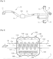
- FIG. 1 is a schematic perspective view of a service tube for conveying cooling air taken from a high-pressure compressor module incorporating a filtration device according to the invention.
- FIG. 2 more particularly illustrates an exemplary embodiment of a filtration device according to the invention, in partial axial section along the longitudinal axis of the device.
- FIG. 3 more particularly illustrates a transverse slice of the spiral tube of the filtration device according to the invention.
- FIG. 4 is a schematic diagram illustrating the operation of the filtration device according to the invention.
- FIG 5 an exterior view of the filtration device illustrated in figure 2 .
- FIG 6 a partial sectional view along a longitudinal plane of the filtration device illustrated in figure 2 , the cut being made between the outer protective casing and the storage tank inside the filtration device illustrated in figure 2 .
- FIG. 1 is a schematic perspective view of a service tube 10 for conveying cooling air taken from a high-pressure compressor module, integrating a filtration device 100 according to the invention.
- FIG. 1 More particularly illustrates an exemplary embodiment of a filtration device 100 according to the invention, in partial axial section along the longitudinal axis of the device.
- the filtration device 100 is intended to filter a cooling air flow F used for cooling a low pressure turbine, and more particularly for cooling the rotor of the low pressure turbine.
- the cooling air flow F is taken from an upstream part of the low-pressure turbine, for example from the high-pressure compressor of the turbomachine, and is routed to an inter-turbine casing, (or TCF “Turbine Center Frame” according to the generally used Anglo-Saxon terminology), via a supply pipe, called “service tube 10”, shown in [ fig 1 ].
- the service tube 10 comprises an upstream end 11 connected to a part of the high-pressure compressor and configured to allow sampling of a cooling air flow F, and at least one downstream arm with a downstream distribution end 12 configured to be connected to an injection hole of the inter-turbine casing (the service tube 10 illustrated as an example in [ fig 1 ] comprises two servitude arms 18 each having a downstream distribution end 12).
- the filtration device 100 is advantageously positioned on this service tube 10 between the upstream end 11 and the downstream end 12.
- the filtration device 100 is interposed between an upstream tube 14 and a downstream tube 16 of the service tube 10.
- the filtration device 100 comprises a conduit 110 in the form of a spiral or circular helix inscribed on a cylinder of revolution with an axis of revolution (Ox).
- the conduit 110 is formed according to the exemplary embodiment illustrated by a tube with a circular section.
- the spiral tube 110 forming the conduit has an upstream end 111 configured to be coupled to the upstream tube 14 of the service tube 10 and a downstream end 112 configured to be coupled to the downstream tube 16 of the service tube 10.
- the upstream ends 111 and 112 of the spiral tube 110 are secured respectively to the upstream 14 and downstream 16 tubes via ad hoc fixing means, for example by a system of flanges and bolted connections.
- the spiral tube 110 has a generator drawn in the form of a circular helix, or screw, around a cylinder of revolution with an axis of revolution Ox.
- the spiral tube 110 has a plurality of loops extending axially along the axis of revolution Ox, and has a general corkscrew shape.
- the spiral tube 110 comprises a plurality of openings 114 formed at a radially external portion 115 of the spiral tube relative to an axis of revolution Ox substantially parallel to the longitudinal axis L.
- the openings 114 are made over the entire length of the spiral tube 110, that is to say between the upstream end 111 and the downstream end 112 of the spiral tube 110.
- openings 114 on one or more portions distributed along the length of the spiral tube 110.
- the diameter of the openings 114 is determined according to the size of the particles that one wishes to filter or extract from the air flow F.
- the openings 114 may have a diameter of 2 mm.
- the cooling air flow F circulating at a speed V1 and at a pressure P1 in the upstream tube 14 of the service tube 10 is centrifuged by circulation inside the spiral tube 110.
- the spiral tube 110 is a static element having a geometry allowing centrifugation of a cooling air flow F.
- Centrifugation of the cooling air flow F allows the sand particles 120 to be separated from the air flow by their density difference.
- the cooling air flow F and the sand particles 120 are subjected to a centrifugal force imposed by the helical shape of the spiral tube 110.
- the sand particles 120 are thus projected towards a portion 115 of the spiral tube 110 radially external to the axis of revolution Ox and the sand particles 120 are expelled from the spiral tube 110 via the openings 114.
- the filtration device 100 comprises a storage tank 130 for receiving the sand particles 120 filtered from the cooling air flow F and expelled from the spiral tube 110.
- the storage tank 130 surrounds the spiral tube 110, that is, the spiral tube 110 is housed inside the storage tank 130.
- the storage tank 130 forms an enclosure of which at least one outer wall forming the envelope of the enclosure is porous to air but does not allow the passage of filtered particles, and in particular filtered sand particles 120.
- the sand particles 120 filtered from the cooling air flow F accumulate in the bottom of the storage tank 130 under the effect of gravity as illustrated in [ fig 2 ].
- the storage tank 130 is for example a porous fabric or a porous metal enclosure surrounding the spiral tube 110.
- the filtration device 100 comprises a protective enclosure 140 forming the outer casing of the filtration device 100.
- the protective enclosure 140 is positioned around the storage tank 130 as well as around the coupling portions between the service tube 10 and the spiral tube 110.
- the protective enclosure 140 comprises an upstream fixing system 141 and a downstream fixing system 142 making it possible to fix the protective enclosure respectively on the upstream tube 14 and the downstream tube 16 of the service tube 10.
- the protective enclosure 140 essentially has a role of protecting the device 100, and in particular the spiral tube 110, from various external shocks or attacks.
- the filtration device 100 further comprises means 144 for securing the storage tank 130 to the protective enclosure 140.
- the storage tank 130 is self-supporting and can be centered inside the protective enclosure 140 as illustrated in [ fig 2 ].
- the means 144 for securing the storage tank 130 to the protective enclosure 140 are also configured to limit and/or absorb significant movements, vibrations, etc. of the storage tank 130 inside the protective enclosure 140.
- the protective enclosure 140 also includes openings 146, in particular to allow fluid communication, that is to say an exchange of air, between the exterior and the interior of the protective enclosure 140.
- openings 146 in particular to allow fluid communication, that is to say an exchange of air, between the exterior and the interior of the protective enclosure 140.
- the dimensions of the openings 146 provided at the protective enclosure 140 are determined so as to guarantee a pressure P1 inside the spiral tube 110 greater than the pressure P2 inside the protective enclosure 140, while minimizing the loss of flow rate of the cooling air flow F taken from the high-pressure compressor compartment.
- the air flow rate at the outlet of the filtration device 100 is maximized to ensure good cooling downstream of the filtration device 100, and in particular of the low-pressure turbine rotor.
- the openings 146 are uniformly distributed over at least a portion of the surface of the protective enclosure 140.
- the protective enclosure 140 comprises access to the storage tank 130.
- the protective enclosure 140 may include an access hatch 148 provided with a removable panel 149 providing the possibility of accessing the storage tank 130 when the removable panel 149 is in the open position and allowing to protect the elements inside the protective enclosure 140 when the removable panel 149 is in the closed position.
- the storage tank 130 Opposite the access hatch 148 of the protective enclosure 140, the storage tank 130 also comprises an opening 132 provided at its outer casing allowing access to the sand particles 120 stored in the storage tank 130, from outside the filtration device 100.
- the opening 132 is for example an access hatch having a removable panel between an open position and a closed position.
- the opening 132 of the storage tank is shown in transparency on the [ fig 5 ].
- the access hatches 148, 132 are sized to allow a visual check of the filling of the storage tank and/or for the passage of a suction pipe 151 of a vacuum cleaner 150.
- the access hatches 148, 132 must be large enough to be able to suck up all the particles present in the storage tank 130.
- the filtration device 100 therefore makes it possible to facilitate the extraction of stored sand particles 120, during maintenance operations or during engine control operations.
- the filtration device 100 may also comprise a filling detector making it possible to communicate the filling rate of the sand particles 120 of the storage tank 130, for example by real-time communication of the filling rate, or by the emission of an alarm signal when a threshold filling rate is exceeded.
Landscapes
- Engineering & Computer Science (AREA)
- Chemical & Material Sciences (AREA)
- Chemical Kinetics & Catalysis (AREA)
- Mechanical Engineering (AREA)
- General Engineering & Computer Science (AREA)
- Combustion & Propulsion (AREA)
- Physics & Mathematics (AREA)
- Geometry (AREA)
- Centrifugal Separators (AREA)
- Structures Of Non-Positive Displacement Pumps (AREA)
- Turbine Rotor Nozzle Sealing (AREA)
Description
- Le domaine de l'invention concerne le refroidissement et la ventilation d'une turbine qui équipe une turbomachine, et plus particulièrement une turbine basse pression.
- L'invention concerne plus particulièrement un dispositif de filtration permettant de filtrer un flux d'air de refroidissement d'une turbine basse pression de turbomachine.
- Dans la présente demande, les termes « amont » et « aval » sont définis par rapport au sens d'écoulement normal du gaz (de l'amont vers l'aval) à travers une turbomachine.
- On appelle également « axe de la turbomachine » ou « axe moteur », l'axe de rotation d'un rotor de la turbomachine. La direction axiale correspond à la direction de l'axe de la turbomachine et une direction radiale est une direction perpendiculaire à l'axe de la turbomachine et coupant cet axe. De même, un plan axial est un plan contenant l'axe de la turbomachine, et un plan radial est un plan perpendiculaire à cet axe.
- Sauf précision contraire, les adjectifs « intérieur », « interne », « extérieur », « externe » sont utilisés dans la présente demande en référence à une direction radiale de sorte que la partie intérieure d'un élément est, suivant une direction radiale, plus proche de l'axe de la turbomachine que la partie extérieure du même élément.
- De façon classique, une turbomachine comporte d'amont en aval, c'est-à-dire dans le sens d'écoulement des flux de gaz, une soufflante, un ou plusieurs compresseurs, une chambre de combustion, une ou plusieurs turbines, et une tuyère d'éjection des gaz de combustion sortant de la ou des turbines.
- Ainsi, une turbomachine comprend au moins une partie dédiée à la compression de l'air qu'elle admet en entrée. L'air comprimé par le ou les compresseurs pénètre dans la chambre de combustion où il est mélangé à un carburant avant que le mélange résultant ne soit brûlé et produise des gaz de combustion chauds. Ces derniers sont ensuite détendus dans un étage haute pression de la turbine, puis dans au moins un étage basse pression de cette même turbine.
- Ainsi, durant le fonctionnement de la turbomachine, les différents étages de turbine basse pression sont traversés par des gaz de combustion dont la température est très élevée.
- Classiquement, une turbine basse pression, ou haute pression, comporte un ou plusieurs étages, chaque étage étant formé par une série d'aubes fixes, formant un ensemble appelé distributeur, suivi d'une roue de turbine comportant un disque rotor sur lequel des aubes, dites mobiles, sont solidarisées dans des alvéoles. Le distributeur dévie le flux de gaz vers les aubes mobiles de la roue avec un angle et une vitesse appropriés afin d'entrainer en rotation les aubes mobiles et l'ensemble rotor de la turbine.
- Les alvéoles des disques rotor qui reçoivent les pieds des aubes mobiles sont directement exposés aux gaz de combustion, il est donc nécessaire de les refroidir pour éviter tout endommagement des disques.
- Afin de réduire la contrainte de température et d'assurer une durée de vie suffisante des parties de couplages des aubes (pieds d'aube) et des disques (alvéoles), il est connu de les refroidir au moyen d'un air de refroidissement.
- Pour cela, il est connu de prélever une partie de l'air qui s'écoule en dehors de la veine d'écoulement de la turbine basse pression, généralement en amont au niveau d'un compartiment de compresseur haute pression, et d'acheminer cet air de refroidissement, via une conduite d'alimentation, appelé tube de servitude, jusqu'à des injecteurs ménagés au niveau d'un carter inter turbines, (ou TCF « Turbine Center Frame » selon la terminologie anglo-saxonne généralement utilisée). L'air de refroidissement est ainsi injecté dans une cavité inter-disques et distribué via différentes lunules et orifices traversants jusqu'aux alvéoles des différents disques du rotor.
- L'air prélevé au niveau du compartiment compresseur haute pression d'une turbomachine peut contenir des résidus, des particules, comme par exemple des particules de sable. En fonctionnement, ces particules finissent par être acheminées dans la partie rotor de la turbine basse pression et notamment dans la cavité inter-disque où elles s'accumulent notamment sous les viroles des brides annulaires des disques mobiles de la turbine.
- Cette accumulation de particules forme une couche relativement importante, notamment au niveau des faces radialement interne des viroles de bride annulaire, et a pour conséquence d'accroître la masse des disques et donc de la masse centrifugée de la turbomachine, engendrant par conséquent une augmentation des sollicitations mécaniques des différentes pièces tournantes et une diminution de la durée de vue de ces pièces.
- Une deuxième conséquence de cette accumulation de particules est une diminution de l'efficacité du refroidissement par convection des différentes pièces tournantes, et notamment des disques, les particules accumulées faisant office de barrière thermique. Le document
US 2011/067409 divulgue un séparateur de particules centrifuge est prévu pour éliminer les particules telles que les saletés microscopiques ou les particules de poussière de l'air de refroidissement comprimé avant d'atteindre et de refroidir les aubes de turbine ou les aubes de turbine d'un moteur à turbine. - Ainsi, l'invention vise à remédier aux inconvénients précités et propose un dispositif de filtration permettant de purifier encore mieux un flux d'air de refroidissement
prélevé au niveau d'un compresseur de turbomachine par séparation des particules solides, comme du sable, contenu dans le flux d'air prélevé. - Un but de l'invention est de proposer une solution technique permettant de séparer les particules solides, comme du sable, contenu dans le flux d'air prélevé sans freiner considérablement le flux d'air. La solution de l'invention cherche donc à proposer un dispositif de filtration minimisant la perte de charge de manière à garder un refroidissement efficace du rotor de turbine basse pression en aval.
- A cette fin, l'invention a pour objet un dispositif de filtration d'un flux d'air de refroidissement pour le refroidissement d'une turbine basse pression d'une turbomachine, caractérisé en ce qu'il comporte un conduit présentant une géométrie configurée pour mettre en centrifugation ledit flux d'air de refroidissement traversant ledit conduit, ledit conduit présentant des ouvertures dimensionnées pour permettre une séparation des particules solides contenues dans ledit flux d'air de refroidissement mis en centrifugation, ledit conduit présente une forme d'hélice circulaire inscrite sur un cylindre de révolution d'axe de révolution.
- Grâce au dispositif selon l'invention, on réalise une séparation des particules solides contenues dans le flux de refroidissement tout en minimisant les pertes de charge, ce qui permet de garder une vitesse du flux d'air sortant du dispositif de filtration sensiblement identique à la vitesse du flux d'air entrant. Ainsi, la qualité de refroidissement du rotor de la turbine basse pression est conservée.
- Avantageusement, le conduit présente une forme d'hélice circulaire inscrite sur un cylindre de révolution d'axe de révolution. Ainsi, la forme de conduit permet avec un élément statique de mettre en centrifugation le flux d'air de refroidissement le traversant.
- Avantageusement, le conduit est un tube à section circulaire. Ainsi, on minimise davantage les pertes de charge.
- Avantageusement, les ouvertures sont ménagées dans une portion radialement externe dudit conduit par rapport au dit axe de révolution. Ainsi, les ouvertures sont réalisées dans une portion du conduit dans laquelle les particules solides sont dirigées par effet centrifuge.
- Avantageusement, le dispositif de filtration comporte un réservoir de stockage pour le stockage des particules solides séparées dudit flux d'air de refroidissement. Ainsi, les particules solides séparées du flux d'air ne sont pas relâchées dans la turbomachine.
- Avantageusement, le réservoir de stockage présente une enveloppe poreuse à l'air. Ainsi, il n'y a pas de surpression à l'intérieur du réservoir de stockage.
- Avantageusement, le dispositif de filtration comporte une enceinte protectrice formant l'enveloppe extérieure dudit dispositif de filtration. Ainsi, le dispositif de filtration est protégé des chocs et des agressions extérieures.
- Avantageusement, l'enceinte protectrice présente des ouvertures permettant de mettre en communication fluidique l'intérieur de l'enceinte protectrice avec l'extérieur de l'enceinte protectrice. Ainsi, on garantit une pression à l'intérieur de l'enceinte protectrice inférieure à la pression à l'intérieur du conduit ce qui facilite l'expulsion des particules solides du conduit via les ouvertures du conduit.
- Avantageusement, l'enceinte protectrice présente une trappe d'accès positionnée en regard d'une ouverture ménagée au niveau de l'enveloppe extérieure du réservoir de stockage. Ainsi, on garantit une protection de l'intérieur du dispositif de filtration tout en permettant des opérations de nettoyage facilitées.
- L'invention a aussi pour objet un système de refroidissement d'une turbine basse pression comportant un tube de servitude permettant d'acheminer un flux d'air de refroidissement prélevé au niveau d'un compartiment de compresseur haute pression jusqu'à un compartiment de turbine basse pression, ledit tube de servitude comportant un dispositif de filtration, ledit dispositif de filtration étant positionné entre un tube amont relié au compartiment de compresseur haute pression et un tube aval relié au compartiment de turbine basse pression.
- L'invention et ses différentes applications seront mieux comprises à la lecture de la description qui suit et à l'examen des figures qui l'accompagnent.
- Les figures ne sont présentées qu'à titre indicatif et nullement limitatif de l'invention.
- La
figure 1 est une vue schématique en perspective d'un tube de servitude d'acheminement d'un air de refroidissement prélevé au niveau d'un module compresseur haute pression intégrant un dispositif de filtration selon l'invention. - La
figure 2 illustre plus particulièrement un exemple de réalisation d'un dispositif de filtration selon l'invention, en coupe axiale partielle selon l'axe longitudinal du dispositif. - La
figure 3 illustre plus particulièrement une tranche transversale du tube spirale du dispositif de filtration selon l'invention. - La
figure 4 est un schéma de principe illustrant le fonctionnement du dispositif de filtration selon l'invention. - La
figure 5 une vue extérieure du dispositif de filtration illustré à lafigure 2 . - La
figure 6 une vue en coupe partielle selon un plan longitudinal du dispositif de filtration illustré à lafigure 2 , la coupe étant réalisée entre l'enveloppe protectrice extérieure et le réservoir de stockage à l'intérieur du dispositif de filtration illustré à lafigure 2 . - Sauf précision contraire, un même élément apparaissant sur des figures différentes présente une référence unique.
- La [
fig 1 ] est une vue schématique en perspective d'un tube de servitude 10 d'acheminement d'un air de refroidissement prélevé au niveau d'un module compresseur haute pression, intégrant un dispositif de filtration 100 selon l'invention. - La [
fig 2 ] illustre plus particulièrement un exemple de réalisation d'un dispositif de filtration 100 selon l'invention, en coupe axiale partielle selon l'axe longitudinal du dispositif. - Le dispositif de filtration 100 selon l'invention est destiné à filtrer un flux d'air de refroidissement F utilisé pour le refroidissement d'une turbine basse pression, et plus particulièrement pour le refroidissement du rotor de la turbine basse pression.
- Le flux d'air de refroidissement F est prélevé au niveau d'une partie amont de la turbine basse pression, par exemple au niveau du compresseur haute pression de la turbomachine, et est acheminé au niveau d'un carter inter turbines, (ou TCF « Turbine Center Frame » selon la terminologie anglo-saxonne généralement utilisée), via une conduite d'alimentation, appelé « tube de servitude 10 », représentée à la [
fig 1 ]. - Le tube de servitude 10 comporte une extrémité amont 11 reliée à une partie du compresseur haute pression et configuré pour permettre un prélèvement d'un flux d'air de refroidissement F, et au moins un bras aval avec une extrémité aval 12 de distribution configurée pour être connectée à un trou d'injection du carter inter-turbines (le tube de servitude 10 illustré à titre d'exemple à la [
fig 1 ] comporte deux bras de servitude 18 présentant chacun une extrémité aval 12 de distribution). - Le dispositif de filtration 100 selon l'invention est avantageusement positionné sur ce tube de servitude 10 entre l'extrémité amont 11 et l'extrémité aval 12. Ainsi, le dispositif de filtration 100 est intercalé entre un tube amont 14 et un tube aval 16 du tube de servitude 10.
- En référence à la [
fig 2 ], le dispositif de filtration 100 selon l'invention comporte un conduit 110 en forme de spirale ou d'hélice circulaire inscrite sur un cylindre de révolution d'axe de révolution (Ox). Le conduit 110 est formé selon l'exemple de réalisation illustré par un tube à section circulaire. - Le tube en spirale 110 formant le conduit présente une extrémité amont 111 configurée pour être couplée au tube amont 14 du tube de servitude 10 et une extrémité aval 112 configurée pour être couplée au tube aval 16 du tube de servitude 10.
- Les extrémités amont 111 et 112 du tube spirale 110 sont solidarisées respectivement aux tubes amont 14 et aval 16 via des moyens de fixation ad hocs, par exemple par un système de brides et de liaisons boulonnées.
- Le tube spirale 110 présente une génératrice tracée en forme d'hélice circulaire, ou de vis, autour d'un cylindre de révolution d'axe de révolution Ox. Ainsi, le tube spirale 110 présente une pluralité de boucles s'étendant axialement le long de l'axe de révolution Ox, et présente une forme générale en tire-bouchon.
- Comme représenté à la [
fig 2 ] et plus particulièrement à la [fig 3 ] qui illustre particulièrement une tranche transversale du tube spirale 110 du dispositif de filtration 100 selon l'invention, le tube spirale 110 comporte une pluralité d'ouvertures 114 ménagées au niveau d'une portion 115 radialement externe du tube spirale par rapport à un axe de révolution Ox sensiblement parallèle à l'axe longitudinal L. - Avantageusement, les ouvertures 114 sont réalisées sur toute la longueur du tube spirale 110, c'est-à-dire entre l'extrémité amont 111 et l'extrémité aval 112 du tube spirale 110.
- Selon une variante de réalisation, il est également envisagé de réaliser des ouvertures 114 sur une ou plusieurs portions réparties sur longueur du tube spirale 110.
- Le diamètre des ouvertures 114 est déterminé en fonction de la taille des particules que l'on souhaite filtrer ou extraire du flux d'air F.
- A titre d'exemple, pour une filtration de particules de sable ayant un diamètre de 0,01 à 2mm, les ouvertures 114 peuvent présenter un diamètre de 2mm.
- Grâce au dispositif de filtration 100 selon l'invention, le flux d'air de refroidissement F circulant à une vitesse V1 et à une pression P1 dans le tube amont 14 du tube de servitude 10 est mis en centrifugation par circulation à l'intérieur du tube spirale 110.
- Ainsi, le tube spirale 110 est un élément statique présentant une géométrie permettant une mise en centrifugation d'un flux d'air de refroidissement F.
- La centrifugation du flux d'air de refroidissement F permet de séparer les particules de sable 120 du flux d'air par leur différence de densité.
- Lors de la circulation à l'intérieur du tube spirale 110, le flux d'air de refroidissement F et les particules de sable 120 sont soumis à une force centrifuge imposée par la forme en hélice du tube spirale 110.
- Comme on peut le voir représenté sur la [
fig 3 ], les particules de sable 120 sont ainsi projetées vers une portion 115 du tube spirale 110 radialement externe par rapport à l'axe de révolution Ox et les particules de sable 120 sont expulsées du tube spirale 110 via les ouvertures 114. - Le dispositif de filtration 100 comporte un réservoir de stockage 130 pour réceptionner les particules de sable 120 filtrées du flux d'air de refroidissement F et expulsées du tube spirale 110.
- Le réservoir de stockage 130 entoure le tube spirale 110, c'est-à-dire que le tube spirale 110 est logé à l'intérieur du réservoir de stockage 130.
- Le réservoir de stockage 130 forme une enceinte dont au moins une paroi extérieure formant l'enveloppe de l'enceinte est poreuse à l'air mais ne permet pas le passage des particules filtrées, et notamment des particules de sable 120 filtrées.
- Ainsi, les particules de sable 120 filtrées du flux d'air de refroidissement F s'accumulent dans le fond du réservoir de stockage 130 sous l'effet de la gravité comme illustré à la [
fig 2 ]. - Le réservoir de stockage 130 est par exemple une toile poreuse ou encore une enceinte métallique poreuse entourant le tube spirale 110.
- En outre, le dispositif de filtration 100 comporte une enceinte protectrice 140 formant l'enveloppe extérieure du dispositif de filtration 100. L'enceinte protectrice 140 est positionnée autour du réservoir de stockage 130 ainsi qu'autour des portions de couplage entre le tube de servitude 10 et le tube spirale 110. A cet effet, l'enceinte protectrice 140 comporte un système fixation amont 141 et un système de fixation aval 142 permettant de fixer l'enceinte protectrice respectivement sur le tube amont 14 et le tube aval 16 du tube de servitude 10.
- L'enceinte protectrice 140 a essentiellement un rôle de protection du dispositif 100, et notamment du tube spirale 110, des divers chocs ou agressions extérieures.
- Le dispositif de filtration 100 comporte en outre des moyens 144 pour solidariser le réservoir de stockage 130 à l'enceinte protectrice 140. Ainsi, le réservoir de stockage 130 est autoporté et peut être centré à l'intérieur de l'enceinte protectrice 140 comme illustré à la [
fig 2 ]. - A titre d'exemple, les moyens 144 pour solidariser le réservoir de stockage 130 à l'enceinte protectrice 140 sont également configurés pour limiter et/ou absorber les mouvements importants, les vibrations, etc du réservoir de stockage 130 à l'intérieur de l'enceinte protectrice 140.
- L'enceinte protectrice 140 comporte également des ouvertures 146, notamment pour permettre une communication fluidique, c'est-à-dire un échange d'air, entre l'extérieur et l'intérieur de l'enceinte protectrice 140. Ainsi, comme représenté par le schéma de principe de la [
fig 4 ], on garantit une pression P1 à l'intérieur du tube spirale 110 supérieure à la pression P2 environnante, et donc une expulsion des particules de sable 120 du tube spirale 110. - En effet, dans le cas où l'enceinte protectrice 140 serait fermée et complètement étanche, on assisterait à un placage des particules de sable 120 à l'intérieur du tube spirale 110 et non à une expulsion des particules par la présence d'une pression à l'intérieur de l'enceinte protectrice 140 supérieure à la pression P1 du flux d'air de refroidissement F circulant à l'intérieur du tube spirale 110.
- Les dimensions des ouvertures 146 ménagées au niveau de l'enceinte protectrice 140 sont déterminées de manière à garantir une pression P1 à l'intérieur du tube spirale 110 supérieure à la pression P2 à l'intérieur de l'enceinte protectrice 140, tout en minimisant la perte de débit du flux d'air de refroidissement F prélevé au niveau du compartiment compresseur haute pression. Ainsi, on maximise le débit d'air en sortie du dispositif de filtration 100 pour assurer un bon refroidissement en aval du dispositif de filtration 100, et notamment du rotor de turbine basse pression.
- A titre d'exemple, les ouvertures 146 sont réparties uniformément sur au moins une portion de la surface de l'enceinte protectrice 140.
- En référence à la [
fig 5 ] qui représente une vue extérieure du dispositif de filtration 100, l'enceinte protectrice 140 comporte un accès au réservoir de stockage 130. - Ainsi, comme représenté à titre d'exemple l'enceinte protectrice 140 peut comporter une trappe d'accès 148 munie d'un panneau amovible 149 donnant la possibilité d'accéder au réservoir de stockage 130 lorsque le panneau amovible 149 est en position ouverte et permettant de protéger les éléments à l'intérieur de l'enceinte protectrice 140 lorsque le panneau amovible 149 est en position fermée.
- En regard de la trappe d'accès 148 de l'enceinte protectrice 140, le réservoir de stockage 130 comporte également une ouverture 132 ménagée au niveau de son enveloppe extérieure permettant un accès aux particules de sable 120 emmagasinée dans le réservoir de stockage 130, depuis l'extérieur du dispositif de filtration 100. L'ouverture 132 est par exemple une trappe d'accès présentant un panneau amovible entre une position ouverte et une position fermée. L'ouverture 132 du réservoir de stockage est représentée en transparence sur la [
fig 5 ]. - Les trappes d'accès 148, 132 sont dimensionnées pour permettre un contrôle visuel du remplissage du réservoir de stockage et/ou pour le passage d'un conduit d'aspiration 151 d'un aspirateur 150. Les trappes d'accès 148, 132 doivent être suffisamment grandes pour pouvoir aspirer toutes les particules présentes dans le réservoir de stockage 130.
- Ainsi, les opérations de maintenance sont facilitées. Compte tenu des accès, il est ainsi possible de vider le réservoir de stockage 130 facilement en utilisant un classique aspirateur 150, comme représenté à la [
fig 6 ]. Le dispositif de filtration 100 selon l'invention permet donc de faciliter l'extraction des particules de sable 120 stockées, lors des opérations de maintenance ou lors des opérations de contrôle moteur. - Le dispositif de filtration 100 peut également comporter un détecteur de remplissage permettant de communiquer le taux de remplissage des particules de sable 120 du réservoir de stockage 130, par exemple par une communication en temps réel du taux de remplissage, ou encore par l'émission d'un signal d'alarme lors du dépassement d'un taux de remplissage seuil.
Claims (9)
- Dispositif de filtration (100) d'un flux d'air de refroidissement (F) pour le refroidissement d'une turbine basse pression d'une turbomachine, caractérisé en ce qu'il comporte un conduit (110) présentant une géométrie configurée pour mettre en centrifugation ledit flux d'air de refroidissement (F) traversant ledit conduit (110), ledit conduit (110) présentant des ouvertures (114) dimensionnées pour permettre une séparation des particules solides contenues dans ledit flux d'air de refroidissement (F) mis en centrifugation, caractérisé en ce que ledit conduit (110)
présente une forme d'hélice circulaire inscrite sur un cylindre de révolution d'axe de révolution (Ox). - Dispositif de filtration (100) d'un flux d'air de refroidissement (F) selon la revendication précédente caractérisé en ce que ledit conduit (110) est un tube à section circulaire.
- Dispositif de filtration (100) d'un flux d'air de refroidissement (F) selon la revendication 2 caractérisé en ce que les ouvertures (114) sont ménagées dans une portion radialement externe dudit conduit par rapport au dit axe de révolution (Ox).
- Dispositif de filtration (100) d'un flux d'air de refroidissement (F) selon l'une des revendications précédentes caractérisé en ce qu'il comporte un réservoir de stockage (130) pour le stockage des particules solides séparées dudit flux d'air de refroidissement (F).
- Dispositif de filtration (100) d'un flux d'air de refroidissement (F) selon la revendication précédente caractérisé en ce que ledit réservoir de stockage (130) présente une enveloppe poreuse à l'air.
- Dispositif de filtration (100) d'un flux d'air de refroidissement (F) selon l'une des revendications précédentes caractérisé en ce qu'il comporte une enceinte protectrice (140) formant l'enveloppe extérieure dudit dispositif de filtration (100).
- Dispositif de filtration (100) d'un flux d'air de refroidissement (F) selon la revendication précédente caractérisé en ce que l'enceinte protectrice (140) présente des ouvertures (146) permettant de mettre en communication fluidique l'intérieur de l'enceinte protectrice (140) avec l'extérieur de l'enceinte protectrice (140).
- Dispositif de filtration (100) d'un flux d'air de refroidissement (F) selon l'une des revendications 6 à 7 caractérisé en ce que l'enceinte protectrice (140) présente une trappe d'accès (148) positionnée en regard d'une ouverture (132) ménagée au niveau de l'enveloppe extérieure du réservoir de stockage (130).
- Système de refroidissement d'une turbine basse pression caractérisé en ce qu'il comporte un tube de servitude (10) permettant d'acheminer un flux d'air de refroidissement (F) prélevé au niveau d'un compartiment de compresseur haute pression jusqu'à un compartiment de turbine basse pression, ledit tube de servitude (10) comportant un dispositif de filtration (100) selon l'une des revendications précédentes, ledit dispositif de filtration (100) étant positionné entre un tube amont (14) relié au compartiment de compresseur haute pression et un tube aval (16) relié au compartiment de turbine basse pression.
Applications Claiming Priority (2)
| Application Number | Priority Date | Filing Date | Title |
|---|---|---|---|
| FR2006237A FR3111376B1 (fr) | 2020-06-16 | 2020-06-16 | Dispositif de filtration d’un air de refroidissement d’une turbine de turbomachine |
| PCT/FR2021/050950 WO2021255360A1 (fr) | 2020-06-16 | 2021-05-26 | Dispositif de filtration d'un air de refroidissement d'une turbine de turbomachine |
Publications (2)
| Publication Number | Publication Date |
|---|---|
| EP4165287A1 EP4165287A1 (fr) | 2023-04-19 |
| EP4165287B1 true EP4165287B1 (fr) | 2024-08-21 |
Family
ID=72470531
Family Applications (1)
| Application Number | Title | Priority Date | Filing Date |
|---|---|---|---|
| EP21734198.1A Active EP4165287B1 (fr) | 2020-06-16 | 2021-05-26 | Dispositif de filtration d'un air de refroidissement d'une turbine de turbomachine |
Country Status (5)
| Country | Link |
|---|---|
| US (1) | US20230220801A1 (fr) |
| EP (1) | EP4165287B1 (fr) |
| CN (1) | CN115768969A (fr) |
| FR (1) | FR3111376B1 (fr) |
| WO (1) | WO2021255360A1 (fr) |
Family Cites Families (17)
| Publication number | Priority date | Publication date | Assignee | Title |
|---|---|---|---|---|
| US1306003A (en) * | 1919-06-10 | Separator | ||
| US1058393A (en) * | 1911-08-14 | 1913-04-08 | Littleton W Turner | Muffler. |
| US1958577A (en) * | 1930-06-12 | 1934-05-15 | Glarence F Hirshfeld | Apparatus for dust separation |
| ES306036A1 (es) * | 1963-12-05 | 1965-03-01 | Polysius Gmbh | Mejoras en la construccion de separadores de fuerza centrifuga. |
| GB2055634B (en) * | 1979-08-16 | 1983-01-26 | Ishikawajima Harima Heavy Ind | Gas-liquid separators |
| US4383917A (en) * | 1980-09-15 | 1983-05-17 | University Of Utah | Apparatus for classifying airborne particulate matter |
| US6178590B1 (en) * | 2000-03-20 | 2001-01-30 | Lindsay Manufacturing, Inc. | Vacuum cleaner cannister with removable bag |
| EP1614879A1 (fr) * | 2004-07-05 | 2006-01-11 | Siemens Aktiengesellschaft | Système et méthode de refroidissement d'une turbine à gaz |
| US10286407B2 (en) * | 2007-11-29 | 2019-05-14 | General Electric Company | Inertial separator |
| NO329085B1 (no) * | 2008-01-31 | 2010-08-16 | Sorbwater Technology As | Fremgangsmate og apparat for separasjon av fluidfaser, samt anvendelser derav |
| US8176720B2 (en) * | 2009-09-22 | 2012-05-15 | Siemens Energy, Inc. | Air cooled turbine component having an internal filtration system |
| AT512446B1 (de) * | 2012-01-24 | 2013-11-15 | Fronius Int Gmbh | Outdorgehäuse mit wechselrichter und gebläse |
| SG11201408506VA (en) * | 2012-07-06 | 2015-03-30 | Practical Analyzer Solutions Pte Ltd | Centrifugal cyclone separator |
| WO2014022344A1 (fr) * | 2012-07-31 | 2014-02-06 | General Electric Company | Capot central en cmc et procédé de fabrication |
| US11090600B2 (en) * | 2017-01-04 | 2021-08-17 | General Electric Company | Particle separator assembly for a turbine engine |
| CN110448960A (zh) * | 2019-09-10 | 2019-11-15 | 班戈设备系统(苏州)有限公司 | 一种风沙环境使用的螺旋除尘设备 |
| WO2021224650A1 (fr) * | 2020-05-06 | 2021-11-11 | Kulakovskij Kirill | Procédé et dispositif de séparation de particules depuis un milieu en écoulement |
-
2020
- 2020-06-16 FR FR2006237A patent/FR3111376B1/fr active Active
-
2021
- 2021-05-26 WO PCT/FR2021/050950 patent/WO2021255360A1/fr not_active Ceased
- 2021-05-26 EP EP21734198.1A patent/EP4165287B1/fr active Active
- 2021-05-26 CN CN202180042950.9A patent/CN115768969A/zh active Pending
- 2021-05-26 US US18/008,906 patent/US20230220801A1/en active Pending
Also Published As
| Publication number | Publication date |
|---|---|
| FR3111376A1 (fr) | 2021-12-17 |
| FR3111376B1 (fr) | 2022-07-22 |
| CN115768969A (zh) | 2023-03-07 |
| US20230220801A1 (en) | 2023-07-13 |
| EP4165287A1 (fr) | 2023-04-19 |
| WO2021255360A1 (fr) | 2021-12-23 |
Similar Documents
| Publication | Publication Date | Title |
|---|---|---|
| WO2010116071A1 (fr) | Prelevement d ' air avec filtre inertiel dans le rotor tandem d ' un compresseur | |
| EP3669964B1 (fr) | Dispositif de séparation d'un mélange air/huile | |
| EP0374004A1 (fr) | Vanne de décharge de compresseur de turboréacteur | |
| EP4405569B1 (fr) | Carter d'injection d'air de refroidissement pour turbine de turbomachine | |
| CA2854316C (fr) | Systeme de chauffage de l'habitacle d'un aeronef muni d'un echangeur thermique annulaire autour de la tuyere d'echappement | |
| FR3075866A1 (fr) | Tube de degazage pour une turbomachine d'aeronef a reducteur | |
| EP3347648B1 (fr) | Dispositif de piégeage de particules pour turbomachine et turbomachine équipée d'un tel dispositif | |
| FR3075868B1 (fr) | Tube de degazage pour une turbomachine d'aeronef a reducteur | |
| FR3119199A1 (fr) | Conduit de decharge a etancheite perfectionnee | |
| FR3075867A1 (fr) | Dispositif de deshuilage d'une enceinte de lubrification de turbomachine | |
| WO2021255360A1 (fr) | Dispositif de filtration d'un air de refroidissement d'une turbine de turbomachine | |
| FR3090035A1 (fr) | Dispositif de deshuilage et d’etancheite d’une enceinte de lubrification de turbomachine | |
| EP2324228B1 (fr) | Dispositif de filtration pour gaz d'echappement | |
| EP1769175B1 (fr) | Dispositif d'etancheite d'une machine tournante | |
| WO2024209157A1 (fr) | Conduit d'échappement d'un banc d'essai de turbine avec double tube | |
| EP3131656B1 (fr) | Filtrage d'un flux gaz/particules | |
| CA2848713C (fr) | Volute a deux volumes pour turbine a gaz | |
| FR3009583A1 (fr) | Turbomachine a organe de deviation d’objets etrangers | |
| FR3065030A1 (fr) | Moteur a combustion interne | |
| EP2841724B1 (fr) | Systeme de decantation d'huile contenue dans des gaz de carter d'un moteur de vehicule automobile | |
| FR3074426A1 (fr) | Systeme de decantation d’huile pour un moteur a combustion interne | |
| FR3068074B1 (fr) | Systeme de combustion a volume constant avec collecteur d'echappement cloisonne | |
| WO2025248187A1 (fr) | Turbomachine à poutre structurelle comprenant un conduit de décharge | |
| FR3162206A1 (fr) | Nacelle de turbomachine équipée d’un évent de ventilation actif | |
| FR3159988A1 (fr) | Dispositif de décharge pour une turbomachine d’aéronef à au moins deux flux. |
Legal Events
| Date | Code | Title | Description |
|---|---|---|---|
| STAA | Information on the status of an ep patent application or granted ep patent |
Free format text: STATUS: UNKNOWN |
|
| STAA | Information on the status of an ep patent application or granted ep patent |
Free format text: STATUS: THE INTERNATIONAL PUBLICATION HAS BEEN MADE |
|
| PUAI | Public reference made under article 153(3) epc to a published international application that has entered the european phase |
Free format text: ORIGINAL CODE: 0009012 |
|
| STAA | Information on the status of an ep patent application or granted ep patent |
Free format text: STATUS: REQUEST FOR EXAMINATION WAS MADE |
|
| 17P | Request for examination filed |
Effective date: 20230113 |
|
| AK | Designated contracting states |
Kind code of ref document: A1 Designated state(s): AL AT BE BG CH CY CZ DE DK EE ES FI FR GB GR HR HU IE IS IT LI LT LU LV MC MK MT NL NO PL PT RO RS SE SI SK SM TR |
|
| DAV | Request for validation of the european patent (deleted) | ||
| DAX | Request for extension of the european patent (deleted) | ||
| GRAP | Despatch of communication of intention to grant a patent |
Free format text: ORIGINAL CODE: EPIDOSNIGR1 |
|
| STAA | Information on the status of an ep patent application or granted ep patent |
Free format text: STATUS: GRANT OF PATENT IS INTENDED |
|
| INTG | Intention to grant announced |
Effective date: 20240229 |
|
| GRAJ | Information related to disapproval of communication of intention to grant by the applicant or resumption of examination proceedings by the epo deleted |
Free format text: ORIGINAL CODE: EPIDOSDIGR1 |
|
| STAA | Information on the status of an ep patent application or granted ep patent |
Free format text: STATUS: REQUEST FOR EXAMINATION WAS MADE |
|
| GRAS | Grant fee paid |
Free format text: ORIGINAL CODE: EPIDOSNIGR3 |
|
| STAA | Information on the status of an ep patent application or granted ep patent |
Free format text: STATUS: GRANT OF PATENT IS INTENDED |
|
| GRAP | Despatch of communication of intention to grant a patent |
Free format text: ORIGINAL CODE: EPIDOSNIGR1 |
|
| GRAA | (expected) grant |
Free format text: ORIGINAL CODE: 0009210 |
|
| STAA | Information on the status of an ep patent application or granted ep patent |
Free format text: STATUS: THE PATENT HAS BEEN GRANTED |
|
| INTC | Intention to grant announced (deleted) | ||
| INTG | Intention to grant announced |
Effective date: 20240705 |
|
| AK | Designated contracting states |
Kind code of ref document: B1 Designated state(s): AL AT BE BG CH CY CZ DE DK EE ES FI FR GB GR HR HU IE IS IT LI LT LU LV MC MK MT NL NO PL PT RO RS SE SI SK SM TR |
|
| REG | Reference to a national code |
Ref country code: GB Ref legal event code: FG4D Free format text: NOT ENGLISH |
|
| REG | Reference to a national code |
Ref country code: CH Ref legal event code: EP |
|
| REG | Reference to a national code |
Ref country code: IE Ref legal event code: FG4D Free format text: LANGUAGE OF EP DOCUMENT: FRENCH |
|
| REG | Reference to a national code |
Ref country code: DE Ref legal event code: R096 Ref document number: 602021017557 Country of ref document: DE |
|
| REG | Reference to a national code |
Ref country code: LT Ref legal event code: MG9D |
|
| REG | Reference to a national code |
Ref country code: NL Ref legal event code: MP Effective date: 20240821 |
|
| PG25 | Lapsed in a contracting state [announced via postgrant information from national office to epo] |
Ref country code: NO Free format text: LAPSE BECAUSE OF FAILURE TO SUBMIT A TRANSLATION OF THE DESCRIPTION OR TO PAY THE FEE WITHIN THE PRESCRIBED TIME-LIMIT Effective date: 20241121 |
|
| REG | Reference to a national code |
Ref country code: AT Ref legal event code: MK05 Ref document number: 1715664 Country of ref document: AT Kind code of ref document: T Effective date: 20240821 |
|
| PG25 | Lapsed in a contracting state [announced via postgrant information from national office to epo] |
Ref country code: NL Free format text: LAPSE BECAUSE OF FAILURE TO SUBMIT A TRANSLATION OF THE DESCRIPTION OR TO PAY THE FEE WITHIN THE PRESCRIBED TIME-LIMIT Effective date: 20240821 Ref country code: PL Free format text: LAPSE BECAUSE OF FAILURE TO SUBMIT A TRANSLATION OF THE DESCRIPTION OR TO PAY THE FEE WITHIN THE PRESCRIBED TIME-LIMIT Effective date: 20240821 Ref country code: FI Free format text: LAPSE BECAUSE OF FAILURE TO SUBMIT A TRANSLATION OF THE DESCRIPTION OR TO PAY THE FEE WITHIN THE PRESCRIBED TIME-LIMIT Effective date: 20240821 Ref country code: GR Free format text: LAPSE BECAUSE OF FAILURE TO SUBMIT A TRANSLATION OF THE DESCRIPTION OR TO PAY THE FEE WITHIN THE PRESCRIBED TIME-LIMIT Effective date: 20241122 Ref country code: PT Free format text: LAPSE BECAUSE OF FAILURE TO SUBMIT A TRANSLATION OF THE DESCRIPTION OR TO PAY THE FEE WITHIN THE PRESCRIBED TIME-LIMIT Effective date: 20241223 |
|
| PG25 | Lapsed in a contracting state [announced via postgrant information from national office to epo] |
Ref country code: BG Free format text: LAPSE BECAUSE OF FAILURE TO SUBMIT A TRANSLATION OF THE DESCRIPTION OR TO PAY THE FEE WITHIN THE PRESCRIBED TIME-LIMIT Effective date: 20240821 |
|
| PG25 | Lapsed in a contracting state [announced via postgrant information from national office to epo] |
Ref country code: LV Free format text: LAPSE BECAUSE OF FAILURE TO SUBMIT A TRANSLATION OF THE DESCRIPTION OR TO PAY THE FEE WITHIN THE PRESCRIBED TIME-LIMIT Effective date: 20240821 |
|
| PG25 | Lapsed in a contracting state [announced via postgrant information from national office to epo] |
Ref country code: AT Free format text: LAPSE BECAUSE OF FAILURE TO SUBMIT A TRANSLATION OF THE DESCRIPTION OR TO PAY THE FEE WITHIN THE PRESCRIBED TIME-LIMIT Effective date: 20240821 Ref country code: IS Free format text: LAPSE BECAUSE OF FAILURE TO SUBMIT A TRANSLATION OF THE DESCRIPTION OR TO PAY THE FEE WITHIN THE PRESCRIBED TIME-LIMIT Effective date: 20241221 |
|
| PG25 | Lapsed in a contracting state [announced via postgrant information from national office to epo] |
Ref country code: HR Free format text: LAPSE BECAUSE OF FAILURE TO SUBMIT A TRANSLATION OF THE DESCRIPTION OR TO PAY THE FEE WITHIN THE PRESCRIBED TIME-LIMIT Effective date: 20240821 |
|
| PG25 | Lapsed in a contracting state [announced via postgrant information from national office to epo] |
Ref country code: ES Free format text: LAPSE BECAUSE OF FAILURE TO SUBMIT A TRANSLATION OF THE DESCRIPTION OR TO PAY THE FEE WITHIN THE PRESCRIBED TIME-LIMIT Effective date: 20240821 Ref country code: RS Free format text: LAPSE BECAUSE OF FAILURE TO SUBMIT A TRANSLATION OF THE DESCRIPTION OR TO PAY THE FEE WITHIN THE PRESCRIBED TIME-LIMIT Effective date: 20241121 |
|
| PG25 | Lapsed in a contracting state [announced via postgrant information from national office to epo] |
Ref country code: RS Free format text: LAPSE BECAUSE OF FAILURE TO SUBMIT A TRANSLATION OF THE DESCRIPTION OR TO PAY THE FEE WITHIN THE PRESCRIBED TIME-LIMIT Effective date: 20241121 Ref country code: PT Free format text: LAPSE BECAUSE OF FAILURE TO SUBMIT A TRANSLATION OF THE DESCRIPTION OR TO PAY THE FEE WITHIN THE PRESCRIBED TIME-LIMIT Effective date: 20241223 Ref country code: PL Free format text: LAPSE BECAUSE OF FAILURE TO SUBMIT A TRANSLATION OF THE DESCRIPTION OR TO PAY THE FEE WITHIN THE PRESCRIBED TIME-LIMIT Effective date: 20240821 Ref country code: NO Free format text: LAPSE BECAUSE OF FAILURE TO SUBMIT A TRANSLATION OF THE DESCRIPTION OR TO PAY THE FEE WITHIN THE PRESCRIBED TIME-LIMIT Effective date: 20241121 Ref country code: NL Free format text: LAPSE BECAUSE OF FAILURE TO SUBMIT A TRANSLATION OF THE DESCRIPTION OR TO PAY THE FEE WITHIN THE PRESCRIBED TIME-LIMIT Effective date: 20240821 Ref country code: LV Free format text: LAPSE BECAUSE OF FAILURE TO SUBMIT A TRANSLATION OF THE DESCRIPTION OR TO PAY THE FEE WITHIN THE PRESCRIBED TIME-LIMIT Effective date: 20240821 Ref country code: IS Free format text: LAPSE BECAUSE OF FAILURE TO SUBMIT A TRANSLATION OF THE DESCRIPTION OR TO PAY THE FEE WITHIN THE PRESCRIBED TIME-LIMIT Effective date: 20241221 Ref country code: HR Free format text: LAPSE BECAUSE OF FAILURE TO SUBMIT A TRANSLATION OF THE DESCRIPTION OR TO PAY THE FEE WITHIN THE PRESCRIBED TIME-LIMIT Effective date: 20240821 Ref country code: GR Free format text: LAPSE BECAUSE OF FAILURE TO SUBMIT A TRANSLATION OF THE DESCRIPTION OR TO PAY THE FEE WITHIN THE PRESCRIBED TIME-LIMIT Effective date: 20241122 Ref country code: FI Free format text: LAPSE BECAUSE OF FAILURE TO SUBMIT A TRANSLATION OF THE DESCRIPTION OR TO PAY THE FEE WITHIN THE PRESCRIBED TIME-LIMIT Effective date: 20240821 Ref country code: ES Free format text: LAPSE BECAUSE OF FAILURE TO SUBMIT A TRANSLATION OF THE DESCRIPTION OR TO PAY THE FEE WITHIN THE PRESCRIBED TIME-LIMIT Effective date: 20240821 Ref country code: BG Free format text: LAPSE BECAUSE OF FAILURE TO SUBMIT A TRANSLATION OF THE DESCRIPTION OR TO PAY THE FEE WITHIN THE PRESCRIBED TIME-LIMIT Effective date: 20240821 Ref country code: AT Free format text: LAPSE BECAUSE OF FAILURE TO SUBMIT A TRANSLATION OF THE DESCRIPTION OR TO PAY THE FEE WITHIN THE PRESCRIBED TIME-LIMIT Effective date: 20240821 |
|
| PG25 | Lapsed in a contracting state [announced via postgrant information from national office to epo] |
Ref country code: DK Free format text: LAPSE BECAUSE OF FAILURE TO SUBMIT A TRANSLATION OF THE DESCRIPTION OR TO PAY THE FEE WITHIN THE PRESCRIBED TIME-LIMIT Effective date: 20240821 Ref country code: SM Free format text: LAPSE BECAUSE OF FAILURE TO SUBMIT A TRANSLATION OF THE DESCRIPTION OR TO PAY THE FEE WITHIN THE PRESCRIBED TIME-LIMIT Effective date: 20240821 Ref country code: RO Free format text: LAPSE BECAUSE OF FAILURE TO SUBMIT A TRANSLATION OF THE DESCRIPTION OR TO PAY THE FEE WITHIN THE PRESCRIBED TIME-LIMIT Effective date: 20240821 |
|
| PG25 | Lapsed in a contracting state [announced via postgrant information from national office to epo] |
Ref country code: EE Free format text: LAPSE BECAUSE OF FAILURE TO SUBMIT A TRANSLATION OF THE DESCRIPTION OR TO PAY THE FEE WITHIN THE PRESCRIBED TIME-LIMIT Effective date: 20240821 |
|
| PG25 | Lapsed in a contracting state [announced via postgrant information from national office to epo] |
Ref country code: CZ Free format text: LAPSE BECAUSE OF FAILURE TO SUBMIT A TRANSLATION OF THE DESCRIPTION OR TO PAY THE FEE WITHIN THE PRESCRIBED TIME-LIMIT Effective date: 20240821 |
|
| PG25 | Lapsed in a contracting state [announced via postgrant information from national office to epo] |
Ref country code: SK Free format text: LAPSE BECAUSE OF FAILURE TO SUBMIT A TRANSLATION OF THE DESCRIPTION OR TO PAY THE FEE WITHIN THE PRESCRIBED TIME-LIMIT Effective date: 20240821 Ref country code: IT Free format text: LAPSE BECAUSE OF FAILURE TO SUBMIT A TRANSLATION OF THE DESCRIPTION OR TO PAY THE FEE WITHIN THE PRESCRIBED TIME-LIMIT Effective date: 20240821 |
|
| REG | Reference to a national code |
Ref country code: DE Ref legal event code: R097 Ref document number: 602021017557 Country of ref document: DE |
|
| PLBE | No opposition filed within time limit |
Free format text: ORIGINAL CODE: 0009261 |
|
| STAA | Information on the status of an ep patent application or granted ep patent |
Free format text: STATUS: NO OPPOSITION FILED WITHIN TIME LIMIT |
|
| PGFP | Annual fee paid to national office [announced via postgrant information from national office to epo] |
Ref country code: DE Payment date: 20250519 Year of fee payment: 5 |
|
| PGFP | Annual fee paid to national office [announced via postgrant information from national office to epo] |
Ref country code: GB Payment date: 20250527 Year of fee payment: 5 |
|
| PGFP | Annual fee paid to national office [announced via postgrant information from national office to epo] |
Ref country code: FR Payment date: 20250526 Year of fee payment: 5 |
|
| 26N | No opposition filed |
Effective date: 20250522 |
|
| PG25 | Lapsed in a contracting state [announced via postgrant information from national office to epo] |
Ref country code: SE Free format text: LAPSE BECAUSE OF FAILURE TO SUBMIT A TRANSLATION OF THE DESCRIPTION OR TO PAY THE FEE WITHIN THE PRESCRIBED TIME-LIMIT Effective date: 20240821 |
|
| REG | Reference to a national code |
Ref country code: CH Ref legal event code: H13 Free format text: ST27 STATUS EVENT CODE: U-0-0-H10-H13 (AS PROVIDED BY THE NATIONAL OFFICE) Effective date: 20251223 |
|
| PG25 | Lapsed in a contracting state [announced via postgrant information from national office to epo] |
Ref country code: LU Free format text: LAPSE BECAUSE OF NON-PAYMENT OF DUE FEES Effective date: 20250526 |
|
| PG25 | Lapsed in a contracting state [announced via postgrant information from national office to epo] |
Ref country code: CH Free format text: LAPSE BECAUSE OF NON-PAYMENT OF DUE FEES Effective date: 20250531 |
|
| REG | Reference to a national code |
Ref country code: BE Ref legal event code: MM Effective date: 20250531 |
|
| PG25 | Lapsed in a contracting state [announced via postgrant information from national office to epo] |
Ref country code: MC Free format text: LAPSE BECAUSE OF FAILURE TO SUBMIT A TRANSLATION OF THE DESCRIPTION OR TO PAY THE FEE WITHIN THE PRESCRIBED TIME-LIMIT Effective date: 20240821 |
|
| PG25 | Lapsed in a contracting state [announced via postgrant information from national office to epo] |
Ref country code: IE Free format text: LAPSE BECAUSE OF NON-PAYMENT OF DUE FEES Effective date: 20250526 |
|
| PG25 | Lapsed in a contracting state [announced via postgrant information from national office to epo] |
Ref country code: BE Free format text: LAPSE BECAUSE OF NON-PAYMENT OF DUE FEES Effective date: 20250531 |